
Submitted:
27 October 2025
Posted:
27 October 2025
You are already at the latest version
Abstract
The representative volume element (RVE) of root-reinforced soil is idealized as a composite comprising a bonded element, formed by a cemented-soil matrix with root inclusions, and inclusions of frictional elements. Based on micromechanics, and with the aid of the Mori–Tanaka method, the LCC method, limit analysis theory, and macro–micro energy-equivalence principles (including both strain energy and dissipated energy), a micromechanical strength criterion for root-reinforced soil is established, revealing the failure mechanisms at the microscale. The previously used stepwise procedure for determining the stationary functional is improved, and the microscale prestress is obtained using the Mori–Tanaka method together with macro–micro strain-energy equivalence. The proposed micromechanical strength criterion reproduces well the strength variation of root-reinforced soil under freeze–thaw cycling.
Keywords:
root-reinforced soil
; freeze-thaw cycles
; strength criterion
; micromechanics
Strength is the ability of material to resist deformation and failure, and it is very important in engineering design. Strength theory is used to determine whether a material will fail under various complex stress states, which are widespread in nature and engineering. Current strength criteria are mainly divided into two categories: macroscopic and microscopic. Each has its own characteristics. Research on macroscopic strength criteria started early and is diverse: some involve few parameters with clear physical meaning but have limited general applicability; others involve more parameters yet are broadly applicable; still others lack clear physical meaning but work well for a particular type of soil. Most macroscopic strength criteria are derived from empirical experimental relations and can generally describe the strength characteristics of a given type of soil well, but they struggle to capture the underlying failure and strength mechanisms. Mciroscopic strength criteria consider the micro-scale features of the constituents, have clearer physical meaning, can better describe soils’ failure and strength mechanisms, and help elucidate the essence of soil strength; however, their formulations are cumbersome, making them inconvenient for practical engineering use, and their mesoscopic parameters are generally difficult to obtain with existing testing techniques. Research on mciroscopic strength criteria is still in its infancy and requires further study to improve their reliability, applicability, and theoretical rigor.
The strength of root-reinforced soils is often influenced by multiple factors, including root species, root architecture (e.g., root-clump shape), root content, and soil water content. In the tests of Wan et al. (2016), Lian et al. (2019), and Feng et al. (2019), roots were found to significantly increase cohesion while having almost no effect on the internal friction angle. Wang et al. (2015) reached similar conclusions for undisturbed grass-rooted soils and, in tests on remolded grass-rooted soils, found an optimal root content that maximizes reinforcement. Hamidifar et al. (2018) reported that roots of vetiver grass can markedly improve soil strength indices, increasing cohesion by 119.6% and the internal friction angle by 81.96%. Maffra et al. (2019) tested rooted and root-free soil samples from Atlantic Forest plantations and found that the strengthening effect also depends on soil type: in sandy soils, roots influence strength mainly through cohesion (increasing it by up to 234%), whereas in clays both cohesion (32%) and internal friction angle (14.4%) increased. Field shear tests by Fan and Su (2008) showed that as soil water content rises, the shear strength of rooted soils decreases significantly. Liu et al. (2021), studying the soil-stabilizing effect of mixed-species root systems on saline loess slopes, reached consistent conclusions: both cohesion and internal friction angle decrease linearly with increasing water content. Gonzalez-Ollauri and Mickovski (2017), examining root reinforcement under different hydrological conditions, found a pronounced increase in internal friction angle and proposed the existence of an optimal soil water content. Overall, even though vegetation may exert some negative effects on soils, balancing the various positive and negative influences leads to the conclusion that plant roots can effectively enhance soil strength, except under extreme conditions such as surface layers with particularly high organic content.
Regarding the effects of freeze–thaw cycling on soil strength, in addition to those mentioned earlier, many scholars have conducted related studies on different soils. Using a basaltic soft clay recycled with gypsum byproduct as the test material, Kamei et al. (2012), and focusing on gypseous soils, Aldaood et al. (2014), both found that freeze–thaw cycles reduce unconfined compressive strength and durability. Han et al. (2018) investigated how freeze–thaw cycles affect the mechanical properties and strength indices of saline soils in western Jilin, grouping test conditions into relatively undamaged, single-factor damage, and dual-factor damage, and proposed an empirical equation with high reliability (R2 > 0.985) to describe the combined effects of freeze–thaw cycles and salinity on strength indices. Ma et al. (2018) examined the dynamic properties of mudstone and sandy mudstone after freeze–thaw cycling, defining two parameters—the dynamic coefficient of freeze–thaw damage and the freeze–thaw damage variable—and found that, for the same number of cycles, mudstone exhibits a higher dynamic coefficient of freeze–thaw damage. Xu et al. (2019) studied the combined effects of freeze–thaw erosion and salt erosion on the strength of loess in northwest China; during the first five freeze–thaw cycles, the ratio of the freeze–thaw damage coefficient to the salt-erosion damage coefficient decreased as cycling progressed, and after more than five cycles, both the freeze–thaw damage coefficient and cohesion decayed to a stable level. Qu et al. (2019), working with cohesive coarse-grained soils from slopes along the Qinghai–Tibet region, found that the number of freeze–thaw cycles is negatively correlated with uniaxial compressive strength, residual strength, elastic modulus, and softening modulus.
To address the nonlinear degradation of frozen soil strength, Fish (1984) proposed a parabolic strength criterion, and Chen et al. (2019) proposed an elliptical criterion. Liao et al. (2016) presented a strength criterion based on a modified critical state framework. Liu et al. (2019) categorized existing strength criteria into three classes and developed a new double-shear strength criterion. Luo et al. (2019), based on a two-phase medium model, proposed a strength criterion for glacial till. Research on meso-scale strength criteria started relatively late. Zhou and Meschke (2018) proposed a micromechanical homogenization approach using the Mori–Tanaka method (Mori and Tanaka, 1973) and the Linear Comparison Composite approach (LCC) (Ortega et al., 2011), treating soil particles as the matrix and ice and water as inclusions, accounting for meso-scale prestress, and derived a meso-scale strength criterion for saturated frozen soils.
The shear strength indices of root-reinforced soils are key design parameters that characterize failure in slope geotechnical engineering. Currently, there are two main approaches to shear strength criteria for rooted soils. One approach explicitly separates the reinforcing effect of roots and superposes it on the soil’s inherent strength; this reinforcement is influenced by multiple factors such as plant species, root content, root diameter, root surface area index, spatial distribution pattern, and depth. The Wu–Waldron model and numerous improvements based on it are representative of this approach. The other approach treats the roots and soil as an integrated whole—the root–soil composite—and analyzes the overall medium using geotechnical strength theory, with the root reinforcement implicitly embedded in the corresponding parameters. From a micromechanical perspective, this paper considers interactions between roots and soil particles and, using the macro–micro energy equivalence principle together with the Mori–Tanaka method, develops a strength criterion for rooted soils under freeze–thaw cycling. This provides a theoretical design basis for geotechnical engineering involving root-reinforced soils.
1. Conceptual Framework for Constructing the Strength Criterion
Test results show that the shear strength of root-reinforced soils is influenced not only by confining pressure but also by root content and the number of freeze–thaw cycles (Luo et al., 2023). If the rooted soil is treated as a single whole, the interaction between roots and soil cannot be captured. As shown in Figure 1, at the macroscopic scale the bonded element is taken as the matrix and the frictional element as the inclusion; a binary-medium representative volume element (RVE) is thus formed by bonded and frictional elements. At the mesoscopic scale, the bonded element itself consists of a cemented-soil matrix with root inclusions.
Through two homogenization steps, this model yields a strength criterion for rooted soils from the meso- to the macro-scale; a schematic of the homogenization procedure is given in Figure 2.
(i) Homogenization I: Homogenizing the cemented-soil matrix with the root inclusions gives the strength criterion Fb for the bonded element. Both the cemented-soil matrix and the roots are modeled as linear elastic; their strength criteria share the same form, and no plastic dissipation occurs during loading. Therefore, an elastic homogenization approach can be used directly to establish the strength criterion of the bonded element, which retains a linear character after homogenization.
(ii) Homogenization II: Homogenizing the bonded and frictional elements yields the macroscopic strength criterion for the rooted soil. The frictional element follows a nonlinear elastoplastic constitutive model; plastic dissipation occurs during loading, and its strength criterion Ff is nonlinear. In addition, during the homogenization of bonded and frictional elements, energy transfer caused by damage to the bonded elements must be considered; this includes both strain energy and dissipated energy. When some bonded elements fail and transform into frictional elements, additional energy dissipation occurs—analogous to the breakage of particle agglomerates—which is an energy-transfer process that must be accounted for in homogenization.
2. Strength Criterion
2.1. Strength Criterion for the Bonded Element (Homogenization Ⅰ)
Defining the mean stress , generalized shear stress, volumetric strain and generalized shear strain as follows:
in which is the unit tensor; , are respectively stress and strain tensor; , are respectively deviatoric stress and deviatoric strain tensor.
Defining the strength for cemented soil matrix Fbm and roots inclusion Fr respectively as follows:
in which and denote the principal stress difference and mean stress, respectively, of the cemented-soil matrix at the failure state; and denote the principal stress difference and mean stress, respectively, of the root inclusions at the failure state; and are the corresponding strength parameters. The strength parameters can be expressed as:
where and are the bulk and shear moduli, respectively, of the cemented-soil matrix; and are the volumetric and shear strains, respectively, of the cemented-soil matrix at the failure state; and are the bulk and shear moduli, respectively, of the root inclusions; and and are the volumetric and shear strains, respectively, of the root inclusions at the failure state.
In a root–soil mixture, take a representative volume element (RVE). The volumes of its parts satisfy
where , , , , denote the volumes of the RVE, the bonded element, the frictional element, the cemented-soil matrix, and the root inclusion, respectively.
Define as the breakage ratio (volume fraction of the frictional element), and as the root volume fraction of the specimen (hereafter referred to as the root content). The volume fraction of roots within the bonded element, , is
Within the bonded element, by the theory of volumetric homogenization, the stresses and strains of the cemented-soil matrix and the root inclusion satisfy:
where and are the stress and strain tensors of the bonded element; and are those of the cemented-soil matrix; and and are those of the root inclusion.
Treating the cemented soil as the matrix and the roots as inclusions within the bonded element, micromechanics and the Mori–Tanaka method give
where and are the stiffness tensors of the cemented-soil matrix and the root inclusion, respectively. The Eshelby tensor of the bonded element with cemented soil as matrix is:
Both the cemented-soil matrix and the root inclusion obey linear elastic constitutive laws (Hooke’s law). The constitutive relation and stiffness tensor of the cemented-soil matrix are:
The constitutive relation and stiffness tensor of the roots are
Solving Eqs. (13)–(22) jointly yields:
where and are the local stress concentration tensors of the cemented-soil matrix and the roots, respectively.
From tensor algebra, any isotropic fourth-order tensor can be expressed as a linear combination of the spherical and deviatoric fourth-order identity tensors. By reducing the fourth-order tensor expressions to second-order matrix form, and since both the cemented-soil matrix and the root inclusions follow linear elastic constitutive models, the resulting second-order matrices are diagonal. After computing the above tensors and simplifying, they can be written as:
At the critical state, Eq.(14) can be rewritten as the following expression through the mean stress and generalized shear stress:
Substituting Eq. (7) and Eq. (8) into Eq. (34), we can obtain
From Eq. (23) and Eq. (25), we have
Substituting the above two equations into Eq. (35), we have
The above equation is the strength criterion of the bonded element, which can be rewritten as the following expression:
It can be seen that the bonded element shares the same mathematical form as the cemented-soil matrix and the root inclusions. Since both the cemented-soil matrix and the root inclusions follow linear elastic constitutive models, the bonded element is a linear combination of the cemented-soil matrix and the root inclusions, which is consistent with linear superposition in elasticity.
The bonded element is a linear elastic material. Prior to damage, it undergoes only elastic deformation without plastic deformation. During loading, only the strain energy of the bonded element changes, with no plastic dissipation. Therefore, at the point of failure, the strain energy and dissipation energy of the bonded element are
Here, and are the volumetric and shear strains of the bonded element at failure; and are the bulk and shear moduli of the bonded element, which can be obtained via the Mori–Tanaka method or other mesomechanics-based approach:
The linear elastic constitutive model of the bonded element is
The nonlinear function of the bonded element can be written as
Here, stat(·) denotes the stationarity operator, i.e., taking the extremum of the function in parentheses. By setting the partial derivatives of the variables to zero at the stationary point and solving the resulting coupled equations, the solution can be obtained.
2.2. Strength Criterion for the Frictional Element
From a micromechanical perspective, failure of granular soils is primarily caused by frictional sliding and shear slip (Zhao et al., 2018), exhibiting pronounced elastoplastic deformation characteristics. The strength of the frictional element is nonlinear, and the failure of soil particles can be well described by either the Mohr–Coulomb strength criterion or an elastoplastic strength criterion. For greater generality, this paper adopts an elliptical strength criterion to represent the strength of the frictional element, namely:
where and are the principal stress difference and mean stress of the frictional element at the critical state; S and M are strength parameters; a is a regularization parameter. As a → 0, , and the elliptical strength criterion degenerates to the D–P criterion.
Because the frictional element undergoes nonlinear elastoplastic deformation during loading, in addition to the conversion of strain energy, plastic dissipation also occurs. The strain energy of the frictional element is nonlinear and difficult to solve directly. Here we employ the Linear Comparison Composite (LCC) method (Castaneda, 2002; Lopez-Pamies and Ponte Castaneda, 2004; Ortega et al., 2011; Wang et al., 2021; Zhou and Meschke,2018) to linearize the constitutive model and obtain an approximate solution for the strain energy. The LCC method refers to linearizing nonlinear features when the components of a composite share similar underlying structures; the nonlinear function Y is a “stationary estimate” of the difference between the microscale maximum dissipation energy and the strain energy of each constituent.
The constitutive model of the frictional element, after LCC-based approximation, is expressed as:
where and are the stress and strain tensors of the frictional element; is the prestress tensor of the frictional element; is the elastic stiffness tensor of the friction element, and is the elastic stiffness of the friction element after linearization; they satisfy, respectively, the following:
At the critical failure point, the prestress satisfies:
where is the prestress stiffness tensor or the linearly corrected stiffness tensor of the friction element, hence:
Regarding the prestress, some researchers directly assume a specific form, while others determine it via limit analysis by setting partial derivatives to zero. In this paper, it is obtained using the macro–meso energy equivalence principle and the Mori–Tanaka method.
Then the strain energy of the friction element can be expressed as:
where and denote the elastic bulk modulus and elastic shear modulus of the friction element; and are the volumetric strain and shear strain of the friction element at failure; and are the volumetric prestress and shear prestress of the friction element.
For the dissipated energy of the friction element, we first define a support function to represent, from a mesoscopic perspective, the maximum energy dissipation associated with the resistance of geomaterials to deformation (Dormieux et al., 2002, 2017; Maghous et al., 2009), namely:
where and are the plastic volumetric strain and plastic shear strain of the friction element at failure. The plastic strain of the friction element can be written as:
The nonlinear function of the friction element is given by
2.3. Dissipated Energy During the Breakage Process
During the gradual failure of a bonded element and its transition into a friction element, energy is both converted and dissipated; this process can be characterized by a breakage stress (Wang et al., 2021). It can be considered that, in the transition from a bonded element to a friction element, energy dissipation predominates. Define the breakage stress as:
The bonded element deforms linearly elastically, and only the friction element undergoes plastic deformation during loading. Therefore, the plastic strain of the breakage process is taken to be the plastic strain of the friction element, i.e.
The damage dissipated energy can be written as
Substituting the constitutive relation of the bonded element into the above gives:
The nonlinear function for the damage process is
2.4. Macroscopic Strength Criterion (Homogenization II)
From a macroscopic perspective, the constitutive model of root-reinforced soil can also be treated using the LCC method, which approximately yields the macroscopic strain energy and dissipated energy. The linearized constitutive model of the RVE for root-reinforced soil is expressed as:
in which , , are the stress tensor, strain tensor, and prestress tensor of the RVE, respectively; is the macroscopic elastic stiffness tensor of the RVE without considering plastic deformation; is the RVE macroscopic stiffness tensor corrected by the LCC method.
From homogenization theory and based on a binary medium model, we have
Substituting the above into the constitutive relations of the RVE, the bonded element, and the friction element, we obtain:
By substituting Eq. (51) into Eq. (65) and comparing, we get:
By computation via the Mori–Tanaka method, the macroscopic elastic stiffness tensor can be expressed as follows:
in which and are the coefficients of the Eshelby tensor for the case with the friction element as the matrix and the cemented element as the inclusion, satisfying the following:
Similarly, the macroscopic stiffness tensor after linearization can be written as:
The strain tensors of the bonded and friction elements satisfy:
where A is the local strain concentration tensor, expressed as
The explicit expression of the local strain concentration tensor is
Substituting Eq.(71) into Eq.(64), we can obtain:
The macroscopic strain energy is expressed as
According to the macro–meso energy equivalence principle, the macroscopic and mesoscopic strain energy densities are equal, namely:
After linearization by the LCC method, the stiffness tensors and the stress/strain tensors of the bonded element, the friction element, and the RVE are all diagonal. Substituting the relevant expressions into Eqs. (75) and (76) reduces them to
The above is a quadratic equation in or . It can be solved using Eq. (54), and we obtain
Solve for using the quadratic formula. According to Eq. (37), the prestress tensor of the friction element and its stiffness tensor can then be determined. Based on the condition and reasonable bounds, discard the root without physical meaning and use the physically meaningful root in subsequent calculations.
According to the LCC method and limit analysis theory, the maximum macroscopic dissipated energy of the homogenized composite is given by a stationary estimate of the macroscopic strain energy plus the volume-fraction-weighted sum of the nonlinear functions. The dissipated energy of the macroscopic RVE is
Regarding the nonlinear functions, some previous researchers computed the stationary function at each step separately, substituted the results into Eq. (79), and then performed another stationarity operation. This approach is questionable because each step’s stationary value corresponds to a particular stress–strain state, and these states may not be mutually consistent. A more reasonable approach is to omit the intermediate stepwise calculations and evaluate the extremum of the stationary functional in a single step using Eq. (79).
The above expression implicitly embodies the macro–meso energy equivalence principle. Substituting Eqs. (56), (61), and (76), which enforce equality of macro and meso strain energies, into Eq. (79), the right-hand side becomes the sum of the dissipated energies at the mesoscopic scale, namely:
Substituting Eqs.(54), (55) and (60) into Eq. (80), we can obtain the following by manipulation:
The above expression must satisfy the strength criterion of the friction element; that is, find the stationary value of the expression subject to the condition in Eq. (32). Substituting Eq. (47) into Eq. (81), solve for the point where the partial derivative is zero.
Similarly, the dissipated energy at the macroscopic scale can be defined as:
where P and Q are the mean stress and the principal stress difference of the RVE of root-reinforced soil at the critical failure state; is the plastic strain tensor at the critical failure state, and and are the plastic volumetric strain and plastic shear strain, which can be written as:
The macroscopic dissipated energy is expressed as
According to the macro–meso energy equivalence principle, the dissipated energies at the macroscopic and mesoscopic scales are equal, from which the macroscopic strength criterion for root-reinforced soil is ultimately obtained:
in which
3. Verification of Strength Criterion
3.1. Parameter Determination
To predict the strength of root-reinforced soil under freeze–thaw cycling, it is necessary to know the parameters of the roots, the cemented soil matrix, and the friction elements, as well as the breakage parameter. The bulk modulus and shear modulus of the roots can be determined directly or indirectly through laboratory tests. In the binary medium model, it can be considered that at the initial stage of loading the specimen is mainly composed of bonded elements, and the breakage ratio is low. Therefore, the bulk modulus and shear modulus of the cemented soil matrix can be approximately determined from the initial slopes of the and curves at 0.2% axial strain in conventional triaxial tests on specimens without roots and without freeze–thaw cycling.
After completion of the triaxial test, the bonded elements are essentially completely damaged; the remolded soil after freeze–thaw and triaxial testing consists predominantly of friction elements. The parameters of the friction elements can be obtained from triaxial tests on the remolded specimens after freeze–thaw and triaxial testing. The elastic bulk and shear moduli and of the friction elements can be approximately determined from the initial slopes of the and curves of these remolded specimens. The strength parameters a, S, and M of the friction elements can be obtained by fitting the strengths measured on the remolded specimens after freeze–thaw and triaxial testing.
For the breakage ratio, many studies have shown that its evolution follows a Weibull distribution function. We recommend the following equation:
where α and β are damage-fraction parameters that can be determined by inverse analysis, and Pa is the standard atmospheric pressure.
3.2. Experimental Verification
The test soil was extracted from Hailuogou, Sichuan Province, China, at an elevation of about 3000 m, from a depth of 0.5–1.0 m below the ground surface (Luo et al., 2023). The soil is a silty sand, and the roots used were from rowan (Sorbus). The roots were about 5 cm long with a diameter of about 5 mm; the mass of a single root was about 1.4 g, corresponding to a mass fraction of 0.292% (on a dry-mass basis), a volume fraction of 0.262%, and a shearing-area fraction of 0.254%. Specimens were prepared at a target dry density of 1.28 g/cm3, with a diameter of 61.8 mm and a height of 125 mm. After specimen preparation, they were vacuumed for 2 hours and then submerged to saturate in water for more than 12 hours. Specimens not subjected to freeze–thaw cycles were tested directly in triaxial compression; for specimens requiring freeze–thaw cycles, they were promptly placed in water to remove bubbles and transferred under water into lidless transparent plastic jars. The jars containing the specimens were labeled and placed in a fully automatic low-temperature freeze–thaw machine to begin cycling. During the freeze–thaw cycles, water could be replenished through the porous stones at the top and bottom ends of the specimen. According to the temperature of the field, one freeze–thaw cycle consisted of cooling from room temperature to −15°C and holding for 12 hours, then heating to 20°C and holding for 12 hours. After the prescribed number of cycles, the specimen was mounted on a triaxial apparatus and tested under room-temperature consolidated drained conditions, with an axial loading rate of 0.1 mm/min and confining pressures of 25, 50, 100, and 200 kPa. The test was terminated when the axial strain reached 15%, which was taken as failure. The test matrix included confining pressures of 25 kPa, 50 kPa, 100 kPa, and 200 kPa; freeze–thaw cycle counts of 0, 1, 5, 15; and root counts of none, 1 root, and 3 roots.
Based on the triaxial test results, the bulk and shear moduli of the roots, the cemented soil matrix, and the frictional element were determined. From the strengths of remolded specimens after freeze–thaw and triaxial testing, the strength parameters a, S, and M of the frictional element were fitted. A computational program was then developed to verify the strength criterion for root-reinforced soils. First, the parameters of the bonded element were obtained using the Mori–Tanaka method; next, by invoking strain-energy conservation, the prestress and the parameters of the frictional element were determined; then, from the dissipated energy, the parameters of the macroscopic strength criterion were derived; finally, the model predictions were obtained according to the relationships under triaxial testing conditions. Under triaxial stress, the mean stress P and the principal stress difference Q are:
Following the parameter-determination procedure described above, the parameters of the strength criterion for root-reinforced soil under freeze–thaw action were ultimately identified by fitting the test data and performing inverse analysis; these are listed in Table 1. Among them, the damage-rate parameter is affected by the number of freeze–thaw cycles: as the number of cycles increases, the parameter α increases and the damage rate rises accordingly, which corroborates the conclusion that freeze–thaw cycling exacerbates damage to the bonded element.
Based on the parameters in Table 1, the strength criterion model for root-reinforced soil was used to predict strengths under different confining pressures, numbers of freeze–thaw cycles, and root contents, as shown in Figure 3 and Figure 4. Figure 3 and Figure 4 indicate that the model-predicted trends of strength for root-reinforced soil under freeze–thaw action are consistent with the experimental results: strength increases with increasing confining pressure, decreases with increasing numbers of freeze–thaw cycles, and increases with higher root content. A comparison between the model predictions and the test data shows that the model can reproduce, with good accuracy, both the magnitude of strength and its variation under freeze–thaw cycling, with small prediction errors.
The proposed strength criterion model is derived on a micromechanical scale and can reasonably capture the micromechanical failure mechanisms of a three-constituent composite. The model requires relatively few parameters, and their physical meanings are clear; except for the damage-rate parameter, the parameters for the cemented soil matrix, the frictional element, and the roots can all be obtained from laboratory tests. In summary, the micromechanics-based strength criterion for root-reinforced soils, which accounts for the effects of freeze–thaw cycling, can provide a reliable basis for engineering practice.
4. Conclusions
Based on a micromechanical model, the RVE of root-reinforced soil is idealized as a three-constituent composite: a matrix of cemented elements—each composed of a cemented-soil matrix with root inclusions—and inclusions of frictional elements. A strength-criterion model for this three-phase composite was established. With the aid of the LCC method, the Mori–Tanaka scheme, and two-phase medium theory, a strength criterion for root-reinforced soil was developed while accounting for the number of freeze–thaw cycles. The model was then used to predict strengths and compared against experimental results. The main findings are summarized as follows:
(i) In the strength-criterion model for root-reinforced soil, the cemented element is treated as the matrix and the frictional element as the inclusion; the cemented element itself consists of a cemented-soil matrix with root inclusions. From a micromechanical perspective, this constructs a strength-criterion model for a three-constituent composite.
(ii) The constitutive model of the frictional element was linearized using the LCC method. Employing the two-phase medium model, micromechanics, macro–micro energy-equivalence principles, and limit analysis, a macroscopic strength criterion was derived for the root-reinforced soil RVE, thereby revealing the damage mechanisms at the microscale. In doing so, the work improves upon certain shortcomings in previous applications of limit analysis used to obtain the stationary function, and, using the Mori–Tanaka method together with macro–micro strain-energy equivalence, inversely determines the prestress and the moduli of the linearized frictional element.
(iii) The parameters of the strength criterion were identified through laboratory test data and inverse analysis. Using the proposed strength-criterion model, the strengths under different confining pressures, numbers of freeze–thaw cycles, and root contents were predicted with good accuracy, consistent with the strength trends observed in root-reinforced soil tests.
Author Contributions
W.L.: writing—original draft, investigation, validation, visualization, formal analysis. F.C.: writing, investigation, data curation, conceptualization, supervision. Y.W.: resources. G.X.: data curation. E.L.: conceptualization, methodology, writing-review and editing, supervision. All authors reviewed the manuscript. Since this study is not attempting to re-publish/publish any third party or author’s previously published material, this section does not apply.
Funding
This research received financial support from the Nature Science Founding of Tibet Autonomous Region (Grant No. XZ202501ZR0092).
Funding Statement
This research received financial support from the Nature Science Founding of Tibet Autonomous Region (Grant No. XZ202501ZR0092).
Consent to Participate
Since this study did not recruit any human subjects, this section does not apply.
Consent to Publish
Since this study is not attempting to re-publish/publish any third party or author’s previously published material, this section does not apply.
Ethical Approval
Since this study did not recruit any human and/or animal subjects, this section does not apply.
Data Availability
The datasets used and/or analyzed during the current study are available from the corresponding author on reasonable request.
Code Availability
Since this study did not use programming code, this section does not apply.
Acknowledgments
The authors gratefully acknowledge financial support from the Nature Science Founding of Tibet Autonomous Region(Grant No. XZ202501ZR0092).
Competing Interests
The authors declare no competing interests.
References
- Aldaood A, Bouasker M, Al-Mukhtar M. Impact of freeze–thaw cycles on mechanical behaviour of lime stabilized gypseous soils. Cold Regions Science and Technology, 2014, 99: 38-45. [CrossRef]
- Castaneda P P. Second-order homogenization estimates for nonlinear composites incorporating field fluctuations: I—theory. Journal of the Mechanics and Physics of Solids, 2002, 50(4): 737-757. [CrossRef]
- Chen D, Wang D, Ma W, et al. A strength criterion for frozen clay considering the influence of stress Lode angle. Canadian Geotechnical Journal, 2019, 56(11): 1557-1572. [CrossRef]
- Dormieux L, Molinari A, Kondo D. Micromechanical approach to the behavior of poroelastic materials. Journal of the Mechanics and Physics of Solids, 2002, 50(10): 2203-2231. [CrossRef]
- Dormieux L, Lemarchand E, Kondo D, et al. Strength criterion of porous media: Application of homogenization techniques. Journal of Rock Mechanics and Geotechnical Engineering, 2017, 9(1): 62-73. [CrossRef]
- Fan C C, Su C F. Role of roots in the shear strength of root-reinforced soils with high moisture content. Ecological engineering, 2008, 33(2): 157-166.
- Feng B, Zong Q, Cai H, et al. Calculation of increased soil shear strength from desert plant roots. Arabian Journal of Geosciences, 2019, 12: 1-12. [CrossRef]
- Fish A M. Thermodynamic model of creep at constant stress and constant strain rate. Cold Regions Science and Technology, 1984, 9(2): 143-161.
- Gonzalez-Ollauri A, Mickovski S B. Plant-soil reinforcement response under different soil hydrological regimes. Geoderma, 2017, 285: 141-150. [CrossRef]
- Hamidifar H, Keshavarzi A, Truong P. Enhancement of river bank shear strength parameters using Vetiver grass root system. Arabian Journal of Geosciences, 2018, 11: 1-11. [CrossRef]
- Han Y, Wang Q, Wang N, et al. Effect of freeze-thaw cycles on shear strength of saline soil. Cold Regions Science and Technology, 2018, 154: 42-53. [CrossRef]
- Kamei T, Ahmed A, Shibi T. Effect of freeze–thaw cycles on durability and strength of very soft clay soil stabilised with recycled Bassanite. Cold Regions Science and Technology, 2012, 82: 124-129. [CrossRef]
- Lian B, Peng J, Zhan H,et al.Mechanical response of root-reinforced loess with various water contents. Soil and Tillage Research, 2019, 193:85-94. [CrossRef]
- Liao M, Lai Y, Wang C. A strength criterion for frozen sodium sulfate saline soil. Canadian Geotechnical Journal, 2016, 53(7): 1176-1185. [CrossRef]
- Liu X, Liu E, Zhang D, et al. Study on effect of coarse-grained content on the mechanical properties of frozen mixed soils. Cold Regions Science and Technology, 2019, 158: 237-251. [CrossRef]
- Liu X, Liu E. Application of new twin-shear unified strength criterion to frozen soil. Cold Regions Science and Technology, 2019, 167: 102857. [CrossRef]
- Liu Y, Hu X, Yu D, et al. Influence of the roots of mixed-planting species on the shear strength of saline loess soil. Journal of Mountain Science, 2021, 18(3): 806-818. [CrossRef]
- Lopez-Pamies O, Ponte Castaneda P. Second-order homogenization estimates incorporating field fluctuations in finite elasticity. Mathematics and Mechanics of Solids, 2004, 9(3): 243-270. [CrossRef]
- Luo F, Liu E, Zhu Z. A strength criterion for frozen moraine soils. Cold Regions Science and Technology, 2019, 164: 102786. [CrossRef]
- Luo W, Xiang B, Liu E, et al. Mechanical properties of rooted soil under freeze–thaw cycles and extended binary medium constitutive model. Scientific Reports, 2023, 13(1): 13607. [CrossRef]
- Ma Q, Ma D, Yao Z. Influence of freeze-thaw cycles on dynamic compressive strength and energy distribution of soft rock specimen. Cold Regions Science and Technology, 2018, 153: 10-17. [CrossRef]
- Maffra C, Sousa R, Sutili F, et al. The effect of roots on the shear strength of texturally distinct soils. Floresta e Ambiente, 2019, 26. [CrossRef]
- Maghous S, Dormieux L, Barthelemy J F. Micromechanical approach to the strength properties of frictional geomaterials. European Journal of Mechanics-A/Solids, 2009, 28(1): 179-188. [CrossRef]
- Mori T, Tanaka K. Average stress in matrix and average elastic energy of materials with misfitting inclusions. Acta metallurgica, 1973, 21(5): 571-574. [CrossRef]
- Ortega J A, Gathier B, Ulm F J. Homogenization of cohesive-frictional strength properties of porous composites: Linear comparison composite approach. Journal of Nanomechanics and Micromechanics, 2011, 1(1): 11-23. [CrossRef]
- Qu Y, Chen G, Niu F, et al. Effect of freeze-thaw cycles on uniaxial mechanical properties of cohesive coarse-grained soils. Journal of Mountain Science, 2019, 16(9): 2159-2170. [CrossRef]
- Wan Y, Xue Q, Liu L, et al. The role of roots in the stability of landfill clay covers under the effect of dry–wet cycles. Environmental Earth Sciences, 2016, 75: 1-9. [CrossRef]
- Wang P, Liu E, Zhi B. An elastic-plastic model for frozen soil from micro to macro scale. Applied Mathematical Modelling, 2021, 91: 125-148. [CrossRef]
- Wang Y, Liu X, Zhang Z, et al. Experimental study on the influence of root content on the strength of undisturbed and remolded grass-root-reinforced soils. Chinese Journal of Geotechnical Engineering, 2015, 37(8): 1405–1410.(in Chinese).
- Xu J, Li Y, Lan W, et al. Shear strength and damage mechanism of saline intact loess after freeze-thaw cycling. Cold Regions Science and Technology, 2019, 164: 102779. [CrossRef]
- Zhao L Y, Zhu Q Z, Shao J F. A micro-mechanics based plastic damage model for quasi-brittle materials under a large range of compressive stress. International Journal of Plasticity, 2018, 100: 156-176.
- Zhou M M, Meschke G. A multiscale homogenization model for strength predictions of fully and partially frozen soils. Acta Geotechnica, 2018, 13(1): 175-193.
Figure 1.
Schematic of the meso-scale binary medium model of root-reinforced soil.
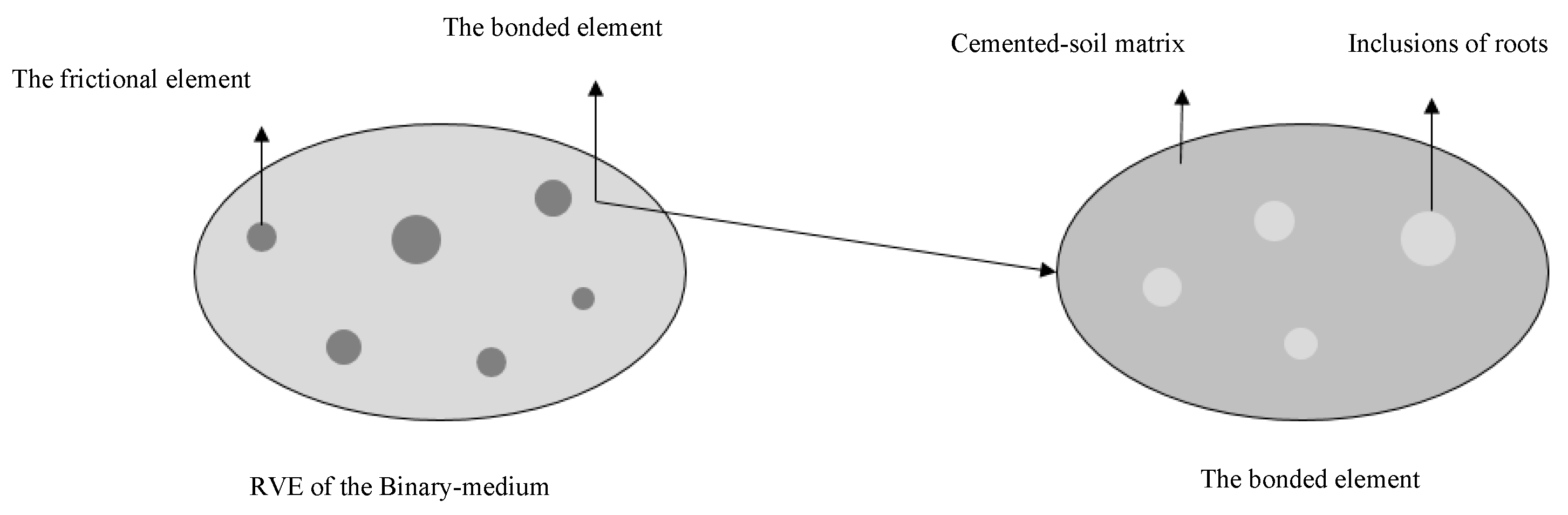
Figure 2.
Schematic of the homogenization steps for the strength criterion of root-reinforced soil.
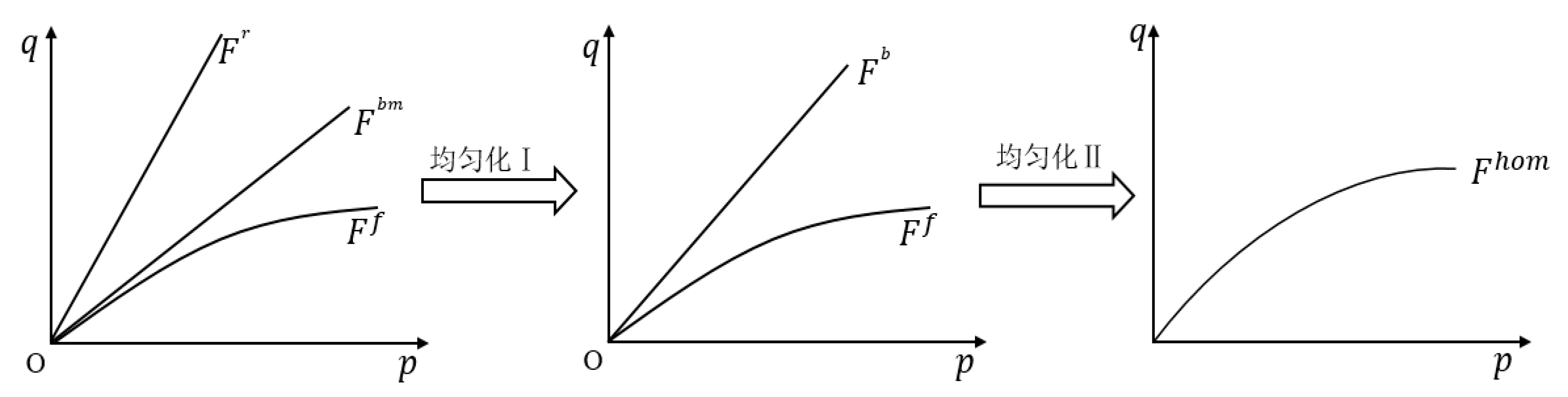
Figure 3.
Comparison of strength predictions and test results under different numbers of freeze–thaw cycles (T: Tested; C: Computed; N: the number of freezing-thawing cycles).
Figure 3.
Comparison of strength predictions and test results under different numbers of freeze–thaw cycles (T: Tested; C: Computed; N: the number of freezing-thawing cycles).
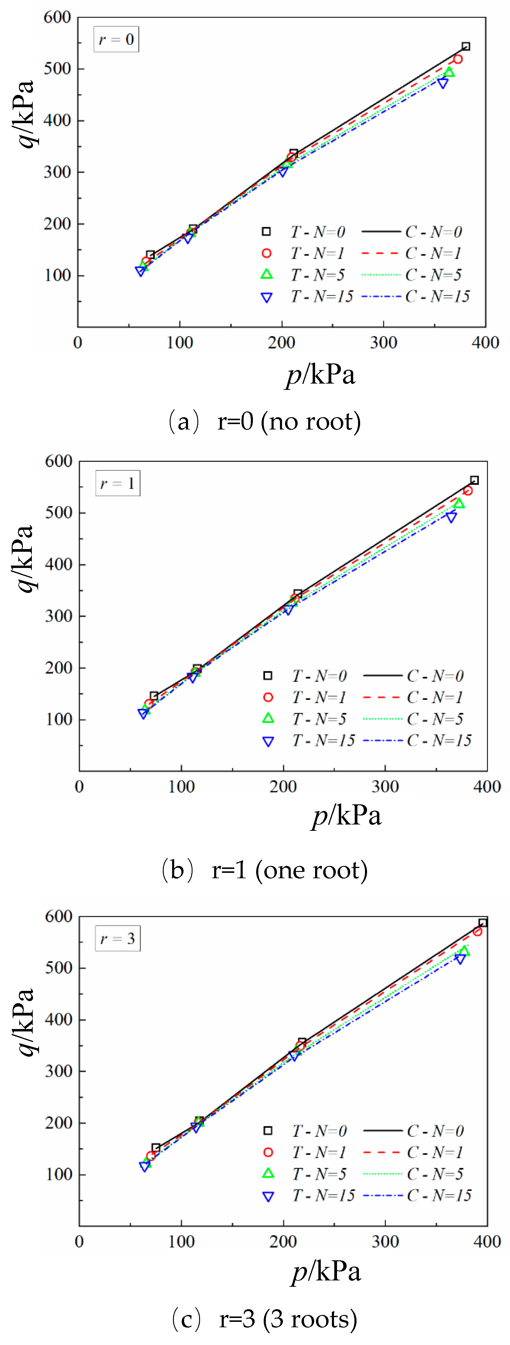
Figure 4.
Comparison of strength predictions and test results for different roots contents (T: Tested; C: Computed; r: the number of roots; N: the number of freezing-thawing cycles).
Figure 4.
Comparison of strength predictions and test results for different roots contents (T: Tested; C: Computed; r: the number of roots; N: the number of freezing-thawing cycles).
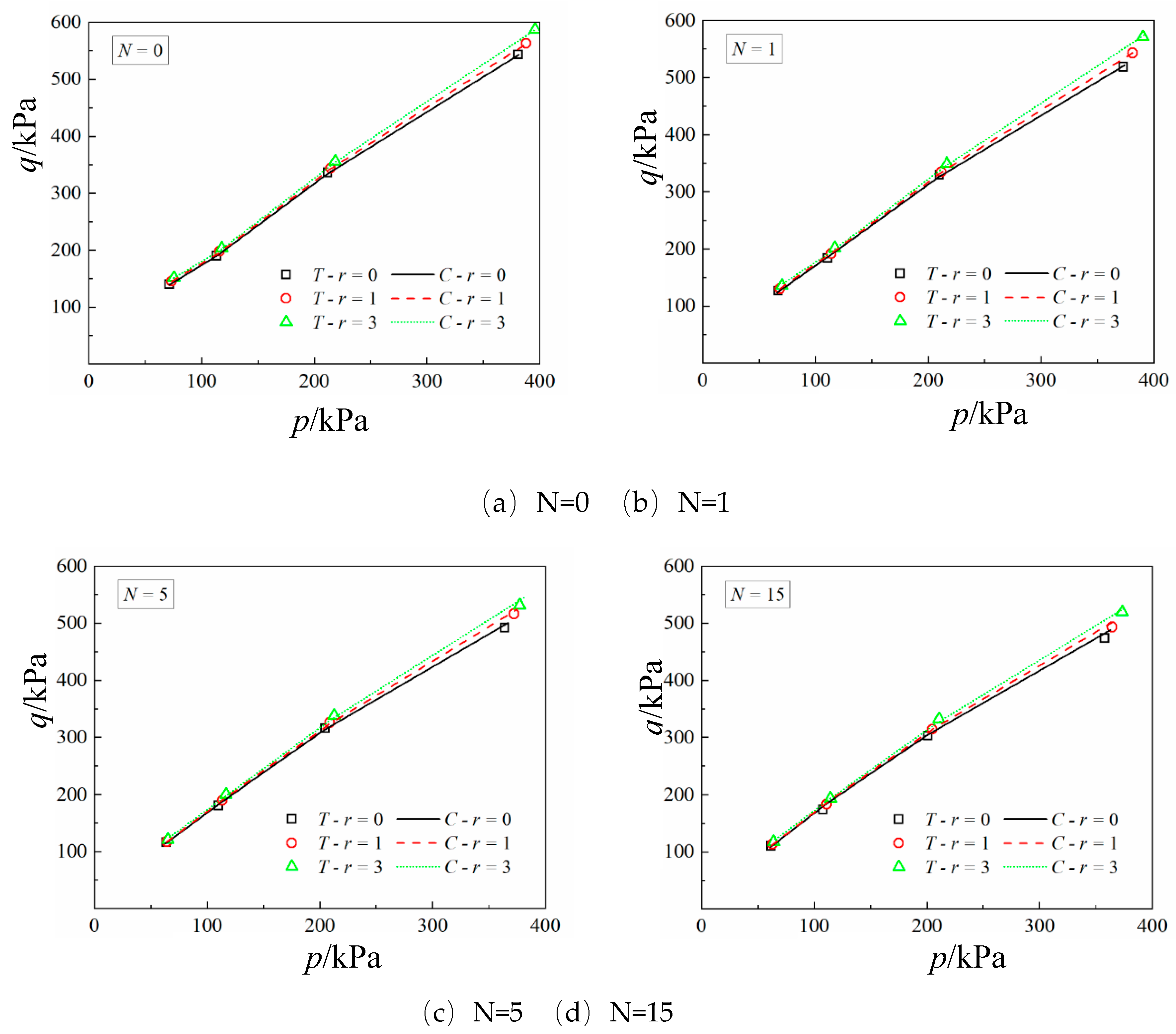

Table 1.
Parameters of strength criterion.
| Parameters | Symbol | Value |
| Bonded element | / kPa | |
| / kPa | ||
| / kPa | 135000 | |
| / kPa | 20250 | |
| Frictional elements | / kPa | |
| / kPa | ||
| 0.01 | ||
| 1.185 | ||
| / kPa | ||
| Breakage ratio | ||
| 0.155 |
Disclaimer/Publisher’s Note: The statements, opinions and data contained in all publications are solely those of the individual author(s) and contributor(s) and not of MDPI and/or the editor(s). MDPI and/or the editor(s) disclaim responsibility for any injury to people or property resulting from any ideas, methods, instructions or products referred to in the content. |
© 2025 by the authors. Licensee MDPI, Basel, Switzerland. This article is an open access article distributed under the terms and conditions of the Creative Commons Attribution (CC BY) license (http://creativecommons.org/licenses/by/4.0/).
Copyright: This open access article is published under a Creative Commons CC BY 4.0 license, which permit the free download, distribution, and reuse, provided that the author and preprint are cited in any reuse.


