Submitted:
26 September 2025
Posted:
29 September 2025
You are already at the latest version
Abstract
Metal additive manufacturing (MAM), also referred to as 3D printing, has proved remarkable in the fabrication of complex metal components in multiple sectors. But the assessment of this revolutionary process through bending fatigue is frequently impeded due to concerns about mechanical and physical conditions of the printed components. The unique layer-by-layer production process results in varied microstructures, anisotropy, and intrinsic defects that considerably differ from traditionally manufactured wrought metals. This review article aims to integrate and evaluate historical and contemporary research on the bending fatigue of additively manufactured materials. More specifically, the impact of process parameters, build orientation, surface conditions, and post processing techniques such as machining, surface treatments, and polishing on bending fatigue performance are summarized. Adopting prediction methodologies were emphasized to facilitate flaw detection and thereby ensuring the safe and reliable deployment of AM parts in dynamic load carrying applications. Some future research directions were proposed, including the i) Development of Standardized specimens and test protocols, ii) adaptation to miniaturization to overcome challenges in high throughput fatigue testing, iii) application of emerging geometries such as the Krouse specimen for mechanistic investigations, and iv) Possibility of developing correlation across different testing methods and materials to reduce experimental burden. By synthesizing the recent progresses and identifying unresolved challenges, this review outlines an organized and clear pathway towards future research for the deployment of advanced bending fatigue characterization in AM process. The novel idea of adapting miniaturized Krouse geometries in bending fatigue test of additively manufactured metals is a viable prospect for the feasible fabrication of AM fatigue coupons with reduced specimen preparation defects and enhanced fatigue strength.
Keywords:
additive manufacturing
; bending fatigue
; krouse specimen
; surface roughness
; post processing
; build orientation
1. Introduction
Metal additive manufacturing has transformed modern manufacturing processes significantly by enabling the creation of intricate shapes with minimal material wastes, minimal machining operations, and reduced assembly requirements. With the help of CAD-CAM integration, this step-by-step material deposition has been a great replacement for many conventional subtractive methods, enabling the production of complex internal structures, lightweight lattices and integrated components [1]. This capability stimulated innovation across high-value industrial and energy sectors such as aerospace, automotive, defense, medical science and nuclear engineering. In aerospace, AM has contributed to the development of lightweight, topology-optimized structural components, fuel nozzles, and turbine parts to reduce weight, improve engine performance and efficiency and enhance the aircraft safety [2,3,4,5,6]. In the medical field, additive manufacturing enables the development of tailored implants, such as orthopedic hip stems, cranial plates, and dental restorations, by leveraging the customization capabilities of digital design [7,8,9,10]. In the automotive sector, AM is utilized for rapid prototyping, precision part tooling and small-scale production of high-performance products for faster innovation cycles and mass customization [11,12,13]. Moreover, by providing efficient, on-demand production of specialized and replacement parts to simplify military logistics and supply chains, additive manufacturing plays a crucial role in national security and the energy sectors by integrating the concept of the Fourth Industrial Revolution (4IR) [14,15,16].
Regardless of these advancements, for the fruitful transition of AM from rapid prototyping to the production of mission-critical, load bearing components, a thorough understanding is required on the mechanical performance of AM metals under end-use operational settings. Among the major performance indicators, fatigue resistance is most critical and challenging to predict and evaluate.
Fatigue, which is the progressive structural damage resulting from cyclical and periodic loads is particularly threatening due to its propensity for catastrophic failure with minimal prior indication. Historically, the majority of fatigue research in additive manufacturing has focused on axial loading conditions. However, numerous real-world components encounter complex stress states that incorporate bending loads.
Specifically, bending fatigue is of growing interest because it more accurately replicates the service loading conditions of a wide variety of structural components. Bridges, beams, shafts, turbine blades, and biomedical implants frequently experience flexural stresses in operation. In bending fatigue, the maximum stress is concentrated at the outermost layers of a component, making surface quality and near-surface defects particularly influential on fatigue performance. Consequently, AM parts—which are known for relatively higher surface roughness, surface-connected porosity, and residual stresses—are at an inherent disadvantage in bending fatigue unless these issues are mitigated through design or post-processing.
AM metals also have distinct micro-structural and flaw characteristics that set them apart from their wrought or cast equivalents. Complex thermal history caused by rapid solidification, localized melting, and repeated melting cycles inherent in AM can lead to highly heterogeneous microstructures [17,18,19]. Melt pool boundaries, unmelted or partially melted particles, columnar grains aligned along the build direction, high dislocation densities, supersaturated matrix and the presence of gas porosity are some other commonly observed features in AM [20,21]. These microstructural abnormalities are due to the layer-wise production nature of AM which could be insidious to fatigue life, particularly when they are located near the surface. Moreover, the mechanical anisotropy caused by the build orientation coupled with the differences in surface roughness can promote premature fatigue crack initiation [22,23,24].
In AM metals, porosity is another major factor that can propagate fatigue cracks faster. Round shaped gas pores from entrapped shielding gases or material vaporization during the powder melting process and lack of fusion defects characterized by sharp, planar voids occur due to inadequate overlap between neighboring melt pools or layers. These defects can drastically diminish the fatigue life by acting as stress concentrators. Fatigue crack initiation and spreads are significantly affected by the position, size and morphology of these defects as detailed by Leuders et al. [25] and Kasperovich et al. [26]. Another aggravating factor that could accelerate the fatigue damage is poor surface roughness. When subjected to cyclic bending loads, surface asperities caused by the stair-stepping effect on the sloping surfaces and the attachment of partially fused powder particles can initiate microcracks [27,28] which will adversely affect fatigue performance.
Residual stresses add an additional layer of complexity to the fatigue performance assessment of AM made parts. In AM, considerable residual stresses are built up near the surface due to the thermal gradients from the cyclical melting and solidification phenomena. The most deleterious of these is the tensile residual stresses, which increase the effective mean stress during cycling loading and hasten the onset and spread of a crack. Multiple researchers have suggested that post-heat treatment for stress relieving and HIP (Hot isostatic press) can considerably reduce these residual stresses and arrest and minimize internal voids to enhance fatigue performance [29,30]. While applying these post-processing techniques is somewhat challenging due to cost, geometry limitation or application constraints, a comprehensive framework could be established that integrates processing variables, alloy compositions, and treatment techniques for an optimal microstructure using AM [31].
While optimization and post-processing have been demonstrated to benefit AM-made parts, accurate measurement and assessment techniques based on dynamic loading will generate stochastically relevant data and provide confidence for the adoption of these AM components. Once such measurement, bending fatigue testing is identified as a sensitive and relevant method for characterizing the fatigue performance of additive manufacturing metals, considering the interplay between these factors. Bending fatigue differs from axial fatigue tests in that it creates a stress gradient, with stress levels reaching zero at the neutral axis and peaking at the surface, rather than applying uniform cyclic stress across the entire cross-section. Bending fatigue serves as an optimal method for investigating surface-initiated fatigue mechanisms, which are prevalent in most additive manufacturing materials. Furthermore, bending fatigue tests can be performed on round, flat, or even miniature specimens, providing adaptability in evaluating various design geometries and accounting for scaling effects.
But the investigation and associated literature on bending fatigue in AM are still sparse in comparison to axial fatigue studies, despite their relevance. A wide range of current researchers focus on common alloys, including Ti-6Al-4V, Inconel 718, and AlSi10Mg. There is a lack of comprehensive studies that investigate the effect of process parameters, build orientations, and post-processing on bending fatigue performance. Again, although a limited number of standards for bending fatigue test exist [32], there are no specific guidelines for their application to AM components.
The appropriate specimen geometries for bending fatigue testing are likewise not universally agreed upon. Flat specimens are more realistic of many real-world components, although round rotating beam specimens are still commonly employed because of their historical precedence and straightforward stress profiles. Miniaturized specimens and unique shapes, such as the Krouse specimen, have also been investigated recently to investigate localized fatigue behavior or to support small AM constructions [33,34]. However, the interpretation and comparison of results across various specimen types are complicated by size effects, stress concentration factors, and boundary conditions.
To mitigate these challenges and knowledge gaps, this review aims to provide a complete synthesis of previous and ongoing research on bending fatigue in additively manufactured metals. It reviews the historical evolution of bending fatigue testing to provide context. It then critically evaluates the current body of literature, focusing on the impact of AM process parameters, material systems, surface quality, and post-processing techniques. A special emphasis is placed on the feasibility and limitations of miniaturized testing, and the importance of unique geometries such as the Krouse specimen in understanding fatigue failure mechanisms and their need for AM components. Finally, this study suggests future research areas, standardization efforts, and testing procedures for advancing bending fatigue evaluation in AM.
By emphasizing both the challenges and opportunities in this field, this review contributes to a better understanding of the complex fatigue behavior of AM metals under bending loads, ultimately supporting their safe and reliable use in structural applications where fatigue failure is not an option.
2. Linking Fatigue Testing to Additive Manufacturing Process
Fatigue analysis has a long-term history since its use from the 19th century when a catastrophic railway accident occurred in France. Tracing back to the industrial revolution, this structural failure in metallic components, particularly in the railway axle, prompted an urgent need to understand the long-term behavior of materials subjected to repeated cyclic loading [35]. The first systematic fatigue tests were initiated by August Wohler for the German Railway system. As a groundbreaking effort and for foundational understanding of material degradation under cyclic stress, he developed S-N curves showing the relationship between the applied cyclic stress (S) and the number of cycles to failure(N) [36]. According to Wohler’s method, rotating beam specimens were subjected to fully reversed bending stress causing alternating tension and compression on the outer surfaces of the specimen. The failures of rotating shafts and axles in early railroads and mechanical systems were thus replicated by this method. This configuration and the resulting Wohler’s curve were particularly applicable for ferrous materials such as steels and various grades of irons [37,38]. These metals exhibit a distinct endurance stress threshold below which fatigue failure doesn’t occur, regardless of number of cycles [39]. This fundamental concept has laid the foundation of fatigue testing and its design theory today.
Wohler’s original apparatus needed several revisions and improvements over the decades for more accurate and repeatable fatigue testing. For example, servo-hydraulic testing machines developed in late-20th century were capable of testing more complex structures and shapes, including variable, multi-axial and strain-controlled fatigue tests at both low and high frequencies [40,41]. Despite these advances in axial and tortional fatigue research, bending fatigue needs extra attention due to its significance for components such as beams, shafts and rotating machinery subjected to flexural loads in real world applications.
Necessary standards were developed by ASTM and ISO with proper guidelines and instructions for fatigue tests, but those are limited mainly to axial fatigue testing. As an example, ASTM E468 [42] provides recommendations about data processing and some material and specimen related information that should be reported and recorded although no particular test process was suggested. Similarly, ASTM E606 described a method for a strain-controlled fatigue test which is suitable for low cycle fatigue situations where materials undergo cyclic plastic deformation [43]. However, the only standard found in literature for bending fatigue test is ASTM B593-21 [32] which is applicable for copper-alloy spring materials in the form of flat sheets or strips. While this standard provides researchers with an intensive methodology for test specimens preparation, mountings and type of machines, the suitability of the process to wide range of materials and shapes is yet to be investigated.
As manufacturing processes matured, fatigue testing became more predictive due to the consistent quality and homogeneity of material properties in forged and wrought components. However, these ideas were thrown off by the rise of AM in the late 20th and early 21st centuries. The unusual microstructures, anisotropies, and defect profiles of AM materials make it exceedingly challenging to use conventional fatigue data to predict their performance.
Early studies on AM fatigue, therefore, logically concentrated on axial fatigue because of its relatively easier setup and availability. The first study was done by Rafi et al. [44] and Blandl E et al. [45] on Ti-6Al-4V and AlSi10Mg respectively, and they set the standard for the characteristics of AM metals under tensile cyclic loading. These studies reinforced the essential metrics and variables that affect and quantify AM fatigue behavior, such as the orientation of the build, the roughness of the surface, and any post-processing. Their research indicated that AM materials, especially when they are in their as-built condition, performed much worse than wrought materials because of surface defects and residual stresses. But as AM technologies progressed from making prototypes into structural and functional part production, some problems associated with the limited nature of axial fatigue testing were highlighted. Most of the time, loading conditions in the real world are not uniaxial. In a lot of important applications, like turbine blades, engine parts, and orthopedic implants, parts are subjected to bending-dominated stress states. Such stress profiles create stress gradients that affect crack propagation in a different way from uniaxial loading.
Identifying this deficiency, researchers had initiated investigations into bending fatigue in additive manufacturing materials to more accurately simulate service conditions. One of the initial significant contributions was the research of Ellyson B et al. [46], who performed rotating bending stress tests on additive manufactured Ti-6Al-4V specimens created using selective laser melting (SLM). Their findings again emphasized a pronounced sensitivity to surface roughness and subsurface imperfections, affirming that bending fatigue is considerably affected by surface quality, which is a vital issue in additive manufacturing due to its intrinsically rough surfaces. Romano’s research signified a transformation in the fatigue research community, indicating the necessity to integrate bending fatigue into the assessment framework for additive manufacturing metals [47]. Subsequent studies by researchers such as Leuders S et al. [48] further corroborated this, demonstrating that rotating and flexural bending tests yielded distinct insights into the fatigue damage mechanisms inherent to additive manufacturing, especially when surface defects or build-induced anisotropy were predominant factors.
Ultimately, material engineering needs to adapt to new research and engineering paradigms through their inception and development. There is a significant need to make bending fatigue a top priority as we move away from using monolithic wrought materials and toward a larger spectrum of additive manufacturing components to ensure robust structures in more complex and crucial applications. Such historical perspective is useful for understanding the current state of research and highlights how crucial it is to have standardized bending fatigue tests for metals used in additive manufacturing that are specific to the application.
3. Current Research in Bending Fatigue of AM Metals
Recent research has moved beyond basic property reporting to more in-depth studies of the factors that affect bending fatigue performance. Researchers are now focusing significantly on AM process parameters, resulting surface and internal defects, effective post-processing techniques as well as the predictive methodologies for faster and reliable qualification of AM parts in fatigue-critical applications by reducing reliance on expensive experiments.
3.1. Influence of Process Parameters on Bending Fatigue Performance of AM Metals
The fatigue life of an AM component greatly depends on the parameters chosen during layer-by-layer manufacturing [49,50,51]. In particular, the variables of Laser Powder Bed Fusion (LPBF) and Directed energy deposition (DED) such as laser power, scan speed, hatch spacing, powder particle size and layer thickness dictate the stability of the melt pool and, consequently, the density and microstructure of the final part. Several studies have been carried out to investigate the effect of these parameters and ultimately find the best combination to ensure a better fatigue life. For example, Ramirez et al. investigated the 4 point and 3 point bending fatigue performance of Ti-6Al-4V manufactured by LPBF at different process parameters [52]. According to their observations different laser power and scanning speeds can vary the size, shape, number of surface defects, pores and the surface roughness which are the dominant factors that control fatigue life. Even different printing parameters can cause varying surface defects. For example, as shown in Table 1 [52], for the same laser power 370 W, keyhole (P3) incurred the highest number of defects with larger sizes than porosity (P5) and Lack of Fusion (LOF) (P8). The defect quantity drastically dropped with the low laser power and optimum scanning speed. Interestingly, with same laser power (280W) and scanning speed (1200 mm/s), EOS nominal exhibited lower number of defects of a smaller size compared to EOS nominal due to a different scan strategy.
This study also proved that an improvement of surface roughness from 15 microns to 7 microns, resulted in a fatigue life increase of about 100 cycles by varying scan strategy while keeping the process parameters same as demonstrated in Table 2 [52]. Different hatching offsets, the contour path, and additional contours to remelt the prior printed contours caused improvements in surface smoothness.
Moon et al. [53] found the impact of laser scanning speed and powder layer thickness on pore density, which impacts fatigue life. Particularly, low porosity was achieved at scanning speed lower than 2700 mm/s while porosity increased when using 2700-4250 mm/s (Figure 1) while keeping the same laser power of 400W and a fixed powder layer thickness of 20 microns. This is because at the lower speeds, the melted tracks were mostly straight and regularly overlapped with neighboring paths and with the increase of speeds the irregularity and unevenness were observed to increase due to the loss of stability over scan direction which ultimately caused high surface roughness.
However, at the low cycle fatigue regimes the effect of scanning speed was difficult to distinguish. Ren Y et al. observed that Ti-6Al-4V produced by laser directed energy deposition process (LDED) showed similar fatigue strength up to 10^4 cycles when scanned at 900 and 1500 mm/min scanning velocity. This reason was explained due to the high scatter of LCF data, heterogenous microstructure and the presence of defects in the specimen. Moreover, at lower strain amplitudes, the low cycle fatigue properties were comparable to that of wrought counterparts [55].
On the other hand, rapid and increased formation of porosity was observed at the powder layer thickness above 40 microns at same laser power of 400W and scan speed of 2400 mm/s due to inconsistent melt flow between layers and on the top surface. (Figure 2) [54]. The thicker layer of powdered material was difficult to get fully melted by this laser power, which leads to a gap between layers and the inclusion and predominance of the staircase effect, ultimately increasing the surface roughness.
Hatami et al identified the effect of spattered particles on fatigue strength while printing the specimens on both left- and right-hand side of an LPBF build plate [56]. As illustrated in Figure 3, due to scanning direction being opposite to the direction of gas flow, a higher number of spattered particles accumulated on the left side containing increased oxide inclusions.
These dissimilar inclusions on two sides remained on the material and caused variation in the tensile strength and enhanced fracture initiations which was reflected in their fatigue life [57,58] as displayed in Figure 4 [56].
Some additional observations by numerous researchers regarding the influence of process parameters on bending fatigue performance of several AM-fabricated metals are summarized in Table 3 [52,59,60,61,62,63]. All of these findings collaboratively necessitate optimized printing parameters for better AM materials microstructure and surface finish.
3.2. Impact of Build Orientation on Bending Fatigue Performance
Build orientation significantly affects the fatigue strength as it determines the direction of the grain growth and the orientation of layer lines relative to the principal stress axis, seriously influencing fatigue crack initiation and propagation [64,65,66]. Table 4 summarizes some of the effects of build orientation on bending fatigue performance of different AM metals [67,68,69,70,71,72]. Although the quality of an AM part can vary depending on the material, and printing processes; overall, it turns out that the horizontal or flat orientation exhibits best bending fatigue performance which then starts diminishing with an increase of inclination indicating build orientation effects and anisotropies [73,74,75,76,77]. This could happen for several reasons such as layer adhesion, melt pool boundaries and interfaces along the build direction, stress concentration, defect orientation, anisotropic microstructures, and grain orientation etc. [78,79]. As AM is a layer-by-layer fabrication process, the bond between layers might be weaker than its wrought counterpart, brought on by segregation of materials due to cooling rates or vaporization effects. In such scenarios, a bending load applied parallel to the build orientation causes less harm to these weaker interfaces due to uniform stress distribution along the uniaxial load and build direction. On the contrary, force applied to the vertical layers could accelerate the damage due to high stress concentration at these weak interfaces.
Horizontal orientations were observed to create finer grain size and lower anisotropic trends which ultimately enhanced the material strength according to Hall-Petch effect [80]. These smaller and fine grain sizes are also beneficial to obstruct the crack propagation in fracture surfaces, thereby promoting longer fatigue life [81]. However, many unique and edge case observations contradicting these trends were also prevalent. For example, Dixit S et al. and Sun W et al. identified the highest yield strength and fatigue properties in the specimens fabricated along 45° orientation due to containing higher amounts of <111> grains towards the said direction [82,83]. This crystallographic texture is strong being dense and closely packed, indicating anisotropic behavior. From all of these studies, it is certain that the nature of defects, porosity and thermal properties of an AM made part can considerably affect the fatigue performance related to build orientation.
3.3. Impact of Post-Processing and Surface Treatments
While the exceptional design flexibility of Additive manufacturing (AM) allows for the creation of complex and tailored metal components without the limitations of conventional manufacturing, the as fabricated state of these parts frequently poses considerable difficulties for high-performance applications [84,85]. AM metal components produced through methods like Laser Powder Bed Fusion (LPBF), Directed Energy Deposition (DED), and Electron Beam Powder Bed Fusion (EBPBF) often display increased surface roughness and poor geometric tolerances due to partially melted powder particles and the “staircase” effect on sloped surfaces; internal flaws such as lack-of-fusion voids and gas porosity; and significant residual stress resulting from extreme thermal gradients during these rapid melting and solidification cycles [86,87,88]. These attributes adversely affect mechanical performance, particularly in fatigue-sensitive applications where crack initiation is frequently governed by surface and near-surface defects. These are the facts which make the post-processing and surface treatment essential to transform additive manufacturing parts from their original state into products that meet the strict requirements of the energy, aerospace, biomedical, and automobile industries. There are two primary categories of post-processing techniques: bulk-modifying treatments that enhance the microstructure, eliminate internal porosity, and reduce harmful tensile residual stresses, and surface-focused treatments that smooth the surface, reduce stress concentration points, and create beneficial compressive residual stresses. Some examples of bulk-modifying treatments include stress-relief annealing, hot isostatic pressing (HIP), and solution aging [89,90,91]. All of these techniques summarized in Table 5 [92,93,94,95,96,97,98,99] can be combined to strengthen materials by reducing the initiation and propagation of cracks.
Post processing can increase yield strength, ultimate tensile strength, and especially fatigue life. Ren et al. found a significant improvement in a material’s fatigue performance as a result of the solution treatment and aging (STA) technique. Components exhibited good low cycle fatigue (LCF) lifetimes and were comparable to those of their wrought counterparts at intermediate strain amplitudes [55]. Mower et al. identified significant enhancement in fatigue strength of DMLS produced Ti-6Al-4V when it was treated by HIP process. They observed that irrespective of the orientation of scanning, fatigue strength was observed to be 400-MPa at 5X10⁴ cycles which is much higher than mechanical or electropolished specimens, which ranged around 100-200 MPa (Figure 5) [99].
El Hassanin et al. investigated the rotating bending fatigue performance of Ti-6Al-4V fabricated by L-PBF and E-PBF and surface treatment by CO2 laser polishing [100]. They observed the significant difference in surface roughness between as built and polished specimens that ultimately increased the fatigue life as demonstrated in Figure 6 [100]. For both LPBF and EPBF rotating bending life was increased through polishing by 26% and 1% respectively at the plastic deformation region, 127% and 113% respectively at the elastic zone, 103% and 59% at the infinite zone.
Although Surface roughness is considered to be the dominant factor for fatigue crack initiation, a high level of scatter in fatigue limit measurements occur due to internal defects and coarser microstructures [96]. Therefore, to eliminate surface impurities of the AM metals, surface treatment is essential. But to remove internal pores which are often visible after surface finishing, heat treatment and processes like HIP and stress relieving are crucial. It can therefore be stated that both surface finishing and heat treatment can simultaneously improve the fatigue performance of AM metals. Nakatani et al. analyzed and compared the surface morphology and fatigue life of the EBM manufactured Ti-6Al-4V which are both polished and HIPed [101]. Figure 7 illustrates this phenomenon representing that although the defects/pores could be removed from the as built parts by applying HIP method, surface roughness still remains. This study also proved that fatigue limit of the polished specimens outperformed the as built specimens for both sample groups with and without HIP. According to their findings, for a targeted life cycle of 107, polished specimens showed fatigue strength of approximately 550 MPa, whereas As built with and without HIP could at most achieve the strength of 200 and 100 MPa respectively which is just 1/3rd of the polished specimen (Figure 8).
In additive manufacturing, the as-built parts contain unevenness and irregular shapes due to sintered and partially melted particles during fabrication. To remove those extra materials and to make the part meet tolerance, machining before polishing is often recommended. Parvez M et al. justified the effectiveness of this while comparing the surface profile of machined and polished specimens [102]. They found that the specimens which are both machined and polished exhibit least waviness compared to as built and just polished specimens.
Besides these mechanical and thermal post processing techniques, solution-based surface finishing is also effective specially for the internal surfaces of complex geometries [103,104,105]. Pawan Tyagi et al. experimented on the effectiveness of Chem-polishing and electro-polishing to reduce the surface roughness of SLM manufactured stainless steel 316 [106,107]. According to their investigations, Both electropolished and Chem-polished specimens showed a drastic drop of surface roughness by approximately 80-90% compared to an unpolished specimen. More specifically, electropolishing outperformed, providing an average surface roughness of 48 nm compared to Chem-polishing, acquiring an average surface roughness of 370nm. A similar investigation was performed by Jiang et al. to reduce surface roughness of LPBF produced nickel-based superalloy (Hastelloy X) using electropolishing [108]. They used an environmentally safe electrolyte called deep eutectic solvent (DES) whereby a surface roughness of 1.2 microns could be achieved in just 5 minutes of treatment.
To conclude, in bending fatigue, where stress gradients are highest at the outer layer of a component, improving surface integrity and defect reduction through post-processing and surface treatments has been instrumental in increasing fatigue life by several hundred percent in some alloys. This can ensure the safe use of metals made with additive manufacturing in real life applications.
3.4. Prediction Methodologies for Bending Fatigue Life in AM Metals
Preparing and testing AM specimens are laborious and expensive due to possessing a higher degree of variability in porosity, microstructure, and surface morphology. So, to reduce the dependency on experimentation, researchers are trying to accelerate this understanding based on predictive methodologies such as numerical simulation, probabilistic estimation and data driven machine learning approaches [109,110].
3.4.1. Numerical Approaches
Computational software using Finite Element Analysis (FEA), multiscale modeling, and crystal plasticity simulations are now available to analyze the bending fatigue behavior of AM metals. Optimized process parameters for fabrication can now be obtained in advance by using software like OpenFoam, ANSYS and COMSOL etc. that can narrow down the experimental trial and error processes. By leveraging finite element simulations, maximum stress points, crack initiation location, even fatigue life cycle estimation can be determined by using software like Abaqus and SolidWorks and used to propose corrections for AM component design before printing. For instance, Jalalahmadi B et al. developed a predictive model called DCAM (Digital clone for Additive Manufacturing) for fatigue life prediction and qualification of AM parts [111]. By simulating the entire process, from initial powder characteristics and complex thermal cycles to the final microstructures, they have been able to provide predictions on material characterization across multiple geometries and materials that aligned well with the experimental results. Hedayati R et al. successfully predicted and validated the S-N curve of porous structures of AM fabricated Ti-6Al-4V by using FE solver ANSYS for lower fatigue strength regimes [112]. Incorporating these numerical approaches considerably reduces experimental burden during development.
3.4.2. Probabilistic Estimation
Defects in AM parts are randomly distributed in terms of size, location and morphology. Consequently, failure factors like crack location, and maximum stress are also scattered causing fatigue in AM metals to be inherently stochastic. By treating these characterization features as distributions rather than deterministic values, probabilistic models such as probabilistic fracture mechanics, reliability-based design, extreme value statistics or a Bayesian inference-based framework, can be used to address these uncertainties [113,114,115]. Being especially valuable for bending fatigue, these models are designed by contemplating the fatigue initiation as the weakest link failure event [116] and defects such as pore or lack of fit (LOF) are considered as the statistical populations. For instance, Park et al. provided a Maximum Likelihood Estimation (MLE) and Median Rank Regression (MRR) based quantitative evaluation by using Monte Carlo simulations to determine the effect of number of specimens, test duration and censoring interval on the accuracy of Weibull estimators in the crack initiation test during Stress Corrosion Cracking of a nuclear reactor [117]. A Probabilistic Physics-guided Neural Network (PPgNN) was developed by Chen et al. for modeling fatigue properties of SLM produced Ti-6Al-4V and it was identified that fatigue life is highly sensitive to temperature, layer thickness, laser power, scan speed and hatch offset [118]. Awd et al. presented a Maximum A Posteriori (MAP) algorithm by combining with atomistic simulations for quantifying the microstructural heterogeneity effect of LPBF built Alsi10Mg and Ti-6Al-4V on fatigue performance and validated that the predicted fatigue strength distributions align with experimental high cycle fatigue data [119].
3.4.3. Machine Learning Approaches
Machine learning based bending fatigue performance prediction in AM metals is performed to analyze data-rich features to capture complex, nonlinear relationships between AM process parameters, microstructural characteristics and defects. The process typically starts with data acquisition from experimental fatigue tests; selection of relevant input parameters like laser power, scanning speed, hatch offset, layer thickness, powder particle size, expected surface roughness, residual stress profile and defect rates; training of the model using algorithms such as XGBoost, Support Vector Mechanics (SVM), Random Forest, or Artificial Neural Networks (ANNs); and finally evaluation of the model for accuracy and reliability. Researchers are demonstrating the feasibility of these data driven models for fatigue performance prediction to reduce reliance on pricy physical tests [120,121,122,123,124,125,126]. As evidence, Bao H et al. found the suitability of the SVM models while determining the influence of the defect size, location and morphology on the fatigue life of a SLM built Ti-6Al-4V [127]. Zhang M et al. examined the Neuro-fuzzy based ML method to predict the high cycle fatigue life of LPBF produced stainless steel 316L by using a dataset of the specimens exposed to different process conditions and surface treatments [128]. Tao Shi et al. [129] and Hornas J et al. [130] applied ANN (Artificial Neural Network), RFR (Random Forest Regression) and SVR (Support Vector Regression) model for fatigue life prediction of SLM produced Alsi10Mg and Ti-6Al-4V respectively based on the data of surface imperfections by µCT measurements, stating that among the 3 models used ANN exhibited the highest accuracy with .
Each methodology described above has demonstrated unique importance on bending fatigue analysis of AM metals. Adoption of computational models overcomes the scarcity of experimental datasets, while the probabilistic estimation with the use of machine learning models can quantify the uncertainty of the results by making accurate model interpretation. The efficient integration and successful implementation of these prediction methodologies are crucial for a faster and confident qualification of AM metals in real-life cyclic stress applications.
4. Future Directions for Mitigating Challenges
Despite considerable advancements in understanding bending fatigue in additively manufactured metals, several fundamental challenges remain unanswered. Lack of reproducibility across machines and strong sensitivity to process parameters cause significant variability in fatigue life arising from the complex interaction of defect populations, surface roughness and residual stresses. This variability is further exacerbated due to strong dependence on specimen geometry and build orientation leading to inconsistent microstructure and failure locations. This inconsistency introduces significant uncertainty and risk into reliability analysis and safety-critical cyclic loading applications of AM components. Resolving these difficulties requires extensive post-processing and a large volume of expensive and time-consuming tests. The adaptation to the miniaturization technique can be potentially useful in this scenario for high throughput testing and stochastic quantification by reducing material consumption, cost and time. Unique geometries such as Krouse or notched specimens can be advantageous for statistically capturing scatter in fatigue performance and localized evaluation of AM features due to randomness in defect distribution across the wider gage volume. Moreover, most existing studies focus on axial fatigue, leaving bending fatigue data scarce and underexplored, which can be mitigated by exploring the correlation among the different fatigue testing methods and materials. Finally, standard operating procedures, describing the guideline for preparation methods, acceptable surface quality level and the defects characterization protocols, will reduce inter-study variability and enable direct comparison of results across laboratories. All of these approaches collectively will create a roadmap to develop relevant AM processes for fatigue-critical applications.
4.1. Adapting Miniaturization Concepts
In support of intricate additive manufacturing processes and components made with multiple materials, miniaturized specimens are being investigated to enhance fatigue testing efficiency and minimize material usage, especially for costly alloys or small production runs. [131]. Printing miniaturized specimens requires fewer materials and less effort compared to the conventional full-size coupons. Also, they facilitate the assessment of small, localized features, such as lattice struts within architected additive manufacturing structures, which cannot be evaluated at full scale [132]. Research conducted by Nicoletto et al has shown that miniaturized bending fatigue tests can yield significant data variability while minimizing costs and enhancing throughput [133]. But the advantages of miniaturization could be offset by significant “size effects.” Smaller specimens demonstrate steeper stress gradients and heightened sensitivity to defects, indicating that even a single pore or un-melted particle can significantly influence fatigue life by promoting fatigue crack initiation due to the lower distance between the center of the pores to the surface [134]. Thus, although miniaturization serves as an effective approach for expedited screening, it is essential to implement careful calibration and adhere to scaling laws prior to confidently applying results to full-sized components.
4.2. Application to Unique Geometries
Bending fatigue analysis and results on additively manufactured metals are greatly influenced by the geometry of the specimens. AM technologies inherently provide significant design flexibility while imposing distinct geometric limitations; thus, researchers have modified both traditional and novel specimen designs to investigate fatigue behavior under bending loads. These endeavors are not solely theoretical; they embody the essential requirement to elucidate the relationship between flaws, microstructure, and stress states that dictate the fatigue life of additive manufacturing components and parts.
Conventional round beam specimens have historically been regarded as the benchmark in rotating-bending fatigue testing because they produce uniform, fully reversed stress distributions along the specimen’s circumference. The cylindrical design reduces stress concentrations and offers a relatively defect-insensitive reference for assessing a material’s inherent fatigue characteristics. In additive manufacturing investigations, cylindrical specimens are especially significant for elucidating surface-related fatigue behavior: surface roughness, partially melted particles, and staircase effects often serve as sites for crack initiation, which are distinctly manifested in round geometries.
On the contrary, flat specimens are easier to manufacture if processed directly from plate-like additive manufacturing blocks. They are also indicative of actual physical structures such as panels, thin-walled housings, or brackets. But the use of flat specimens presents specific complexities due to the edge effects in which machined, or as-built edges act as unintentional stress concentrators that promote crack initiation. But modification of edge of the flat specimens and proper machining parameters can eliminate detrimental surface features or roughness, thereby reducing the impact of surface defects and relocating the crack initiation to internal porosity. Consequently, varying failure mechanisms are evident based on the use of round or flat specimens, which complicates direct data comparison across studies. This necessitates the urgent requirement for standardized protocols that delineate specimen preparation, geometry, and surface conditions in additive manufacturing bending fatigue tests such that each target their own failure modes.
Alternatively, researchers are investigating and increasingly experimenting with specialized fatigue specimen design instead of conventional geometries to address the unique challenges associated with additive manufacturing. One such noteworthy geometry is Krouse specimen which is characterized by a flat cantilever-like design and a tapered gage. The specialty of this geometry is that it can generate a uniform stress field along the gage length as justified by Parvez M et al. [135]. Initially created for wrought steels, this method has been rarely implemented in fatigue properties investigation of AM metals [135,136]. Other noteworthy specimens are notched and hourglass-shaped specimens which are intentionally designed to create controlled stress concentrations for directing crack initiations in specific locations. Some studies have been carried out to quantify and compare the notch sensitivity of AM metals with that of wrought materials as well as to investigate the microstructural behavior on those notched features [137,138,139,140]. These geometries are essential for examining the notch sensitivity of additive manufacturing metals and for exploring the fatigue crack initiation and propagation nature at reduced life cycles. While these designs offer insights into worst-case loading conditions, they may obscure the natural crack initiation processes characteristic of as-built additive manufacturing surfaces, where fatigue life is typically influenced by a distribution of randomly located defects rather than a single engineered notch. Consequently, although specialized geometries offer significant advantages for mechanistic investigations, their relevance to operational conditions requires thorough consideration.
Overall, it can be stated that the specimen geometry plays a significant role in fatigue characterization of AM metals. While round specimens are beneficial for testing intrinsic material response, flat specimens are relevant in terms of ease in manufacturing, preparation and representation of many real-world structures. Special geometries like Krouse or notched offer mechanistic insight under controlled conditions. Therefore, to choose the right geometry, standard operating procedures and testing protocols along with robust design guidelines should be established for the best practices in fatigue analysis of AM products.
4.3. Establish Correlation Across Different Fatigue Test Methods
Establishing reliable correlations across different fatigue testing methods and different materials could be a potential way to deal with the issues associated with additively manufactured metals. Axial, bending, and torsional fatigue tests highlight distin.t crack initiation mechanisms such as internal defects in axial loading, surface roughness in bending, and shear-induced flaws in torsion. However, comparing and integrating their fatigue strength results from these different loading modes using theoretical models like stress-life or strain-life models and defect-oriented methodology like “Murakami’s square root of defect area [141]” approach can potentially provide a unified predictive framework for fatigue behavior in additively manufactured metals. Similarly, correlating fatigue behavior among materials with varying microstructural sensitivity can enable researchers to discern overarching trends that will connect process parameters, defect populations, and fatigue life. But the evidence to experimentally prove these relationships is limited. Akiniwa et al. determined the fatigue strength ratio of spring steel under axial and torsional loading at stress cycles and found an almost constant ratio at different fatigue regimes [142]. But another study performed by Kurek et al. found a discrepancy in this ratio () while comparing the bending and torsional strength of different structural materials [143]. They found that the ratio is not constant for all steels except few non-ferrous metals and varies depending on the chemical composition and heat treatment. Therefore, for safe and confident deployment of the correlation concept, more empirical evidence is essential. With proper integration of machine learning frameworks and high throughput miniaturized testing, these correlations can provide better predictive accuracy with minimal physical experimentation.
4.4. Develop Standard Operating Procedures (SOP)
The components fabricated through additive manufacturing processes such as Laser Powder Bed Fusion (LPBF), Directed Energy Deposition (DED) and Electron Beam Powder Bed Fusion (EB-PBF) are being subjected to fatigue loading in service due to their rapid adoption across multiple industries. For safe and reliable deployment of these AM components in cyclic loading applications, developing standard operating procedures is crucial. Although well-established ASTM standards exist for axial fatigue test of wrought metals which discuss specimen preparation, surface finish requirements, test apparatus and provide other documentation [42,43], the bending fatigue test of AM parts drastically lacks such equivalent standards. This led individual researchers to use different specimen geometries, surface conditions coupled with the limited understanding about defect acceptance rates, limit the comparability of the result across studies. Again, due to the dissimilar nature of mechanism of crack initiation between axial and bending fatigue and the distinct defect types present in wrought and AM, the standards developed for axial loading of wrought metals cannot be directly implemented in bending of AM metals. Quite a few researchers have suggested the urgent need to address these issues. For example, Slotwinski J et al. studied, sorted out and suggested the applicability of existing standards in AM testing [144]. Rogers J et al. discussed the applicability of pre-tested fatigue data to AM parts and the limitation of using this data and test methodologies without adjustment for AMs unique microstructural anisotropy and/or unique defect driven behaviors [145]. So, for AM part to be qualified for bending fatigue test with confidence, robust and harmonized protocols should address several aspects as described below:
Specimen Processing: Instructions about specimen preparation from printing to polishing should be well defined. For example, characteristics and classification of powder particles specification, process parameters, build orientation, heat treatment procedures, machining parameters etc. should be standardized.
Surface Treatment: As surface sensitivity for bending fatigue is critical, it is important to outline the acceptable limits of surface roughness at different conditions such as machined, polished versus as built, with or without edge effects etc.; all of which need to be well defined.
Degree of Defect Acceptance and associated Methods: Recommended max defect size, defect distribution and suitable measurement techniques should be standardized to ensure the comparability among multiple studies.
Test Set Up: Standard testing procedure for different fatigue tests like rotating bending, pure bending, 2, 3, 4 points bending should be established with best practice of recommended load ratio, test frequency, and environmental influences.
Correlation among Alternatives: Although direct comparison is not feasible, acceptable ranges in test results between conventional and AM metals; Correlation in test result among axial, bending, and torsional fatigue can be suggested with empirical evidence.
Documentation and Reporting: The test data, process and results can be recorded under a common transparent platform, a concept of Digital Twins to enable virtual access for the researchers for real-time monitoring and meta-analyses.
A combined community effort, involving academic researchers, industrial innovators, individuals from standard organizations, and certification authorities, is required for establishing such a SOP so that anybody can test a unique AM specimen under standard procedures. This will ultimately reduce the gap between academic research and industrial adoption by building confidence to certify an AM part in cyclic loading applications.
5. Conclusions
Additive manufacturing provides a lot of advantages in terms of design freedom and customization, capability of building complex geometries, and faster production. However, its implementation in bending fatigue characterization is still limited due to lack of knowledge in mitigating challenges to fit AM components under realistic cyclic loading conditions. The current review article highlighted those gaps while consolidating historical and contemporary research, summarizing the impact of AM processing parameters, build orientation, and post processing on bending fatigue performance. Additionally, the study also provided a road map towards future research for resolving the difficulties as well as qualifying AM parts for safe deployment in fatigue-critical applications like automotive, nuclear, medical, energy, defense, and aerospace industries. The key observations are summarized as follows:
- Processing parameters play a significant role in surface roughness that determines bending fatigue performance. Although, these are very material, condition and process specific; usually, lower laser power and lower scanning speed provide lower number of defects due to fair control of melt path and avoiding large heat affected zones [52]. Lower powder particle size can significantly improve surface smoothness and fatigue strength due to their excellent melting and reduced staircase effect [54].
- Optimized scan strategy such as choosing a higher hatch offset distance with a higher number of contours can remelt the prior printed contours to reduce surface roughness [52].
- Horizontal build orientation with respect to scan direction exhibits the best bending fatigue performance compared to inclined and vertical orientations due to minimized melt-pool and layer boundaries that could act as failure propagations regions and alleviate stress concentration.
- Post-processing and surface treatment of AM metals significantly improve bending fatigue strength by mitigating two primary limitations, such as surface roughness and near-surface defects. But the effective choice of these techniques strongly relies on the material, processes, and geometry considerations coupled to consumer needs.
- For mitigating challenges associated with fabrication and sample preparation, the role of miniaturization, geometric effects and prediction methodologies need to be thoroughly explored and adapted by developing optimal standard procedures.
Author Contributions
Conceptualization, M.B.U. and S.P.I.; methodology, M.B.U.; software, M.B.U.; validation, M.B.U., S.P.I. and F.L.; formal analysis, M.B.U.; investigation, M.B.U.; resources, F.L.; data curation, M.B.U.; writing—original draft preparation, M.B.U.; writing—review and editing, M.B.U., S.P.I. and F.L.; visualization, M.B.U.; supervision, S.P.I, and F.L.; project administration F.L.; funding acquisition, F.L.
Funding
This project was funded by the Department of Energy contract #DE-SC0018879; and Product innovation and Engineering, LLC. The authors pay sincere gratitude for their financial supports.
Data Availability Statement
No new data were created.
Conflicts of Interest
The authors declare no conflicts of interest.
References
- Beyer, C. Strategic Implications of Current Trends in Additive Manufacturing. J Manuf Sci Eng. 2014, 136. [Google Scholar]
- Najmon, J.C.; Raeisi, S.; Tovar, A. Review of additive manufacturing technologies and applications in the aerospace industry. Additive Manufacturing for the Aerospace Industry. Elsevier; 2019. p. 7–31.
- Uriondo, A.; Esperon-Miguez, M.; Perinpanayagam, S. The present and future of additive manufacturing in the aerospace sector: A review of important aspects. Proc Inst Mech Eng G J Aerosp Eng. 2015, 229, 2132–2147. [Google Scholar] [CrossRef]
- Sacco, E.; Moon, S.K. Additive manufacturing for space: Status and promises. The International Journal of Advanced Manufacturing Technology. 2019, 105, 4123–4146. [Google Scholar] [CrossRef]
- Najmon, J.C.; Raeisi, S.; Tovar, A. Review of additive manufacturing technologies and applications in the aerospace industry. Additive Manufacturing for the Aerospace Industry. Elsevier; 2019. p. 7–31.
- Altıparmak, S.C.; Xiao, B. A market assessment of additive manufacturing potential for the aerospace industry. J Manuf Process. 2021, 68, 728–738. [Google Scholar]
- Rafi, K.; Zhonghong Liu, A.; Di Prima, M.; Bates, P.; Seifi, M. Regulatory and standards development in medical additive manufacturing. MRS Bull. 2022, 47, 98–105. [Google Scholar] [CrossRef]
- Javaid Mohd Haleem, A. Additive manufacturing applications in medical cases: A literature based review. Alexandria Journal of Medicine. 2018, 54, 411–422. [Google Scholar] [CrossRef]
- Salmi, M. Additive Manufacturing Processes in Medical Applications. Materials. 2021, 14, 191. [Google Scholar] [CrossRef]
- Li, C.; Pisignano, D.; Zhao, Y.; Xue, J. Advances in Medical Applications of Additive Manufacturing. Engineering. 2020, 6, 1222–1231. [Google Scholar]
- Leal, R.; Barreiros, F.M.; Alves, L.; Romeiro, F.; Vasco, J.C.; Santos, M.; et al. Additive manufacturing tooling for the automotive industry. International Journal of Advanced Manufacturing Technology. 2017, 92, 1671–1676. [Google Scholar] [CrossRef]
- Vasco, J.C. Additive manufacturing for the automotive industry. Addit Manuf. Elsevier; 2021. pp. 505–30.
- Ganesh Sarvankar, S.; Yewale, S.N. Additive Manufacturing in Automobile Industry. 2019, 7.
- Mcnulty, C.M.; Arnas, N.; Campbell, T.A. Toward the Printed World: Additive Manufacturing and Toward the Printed World: Additive Manufacturing and Implications for National Security Implications for National Security [Internet]. Available online: https://digitalcommons.ndu.edu/defense-horizons.
- Ukoba, K.; Yoro, K.O.; Adeoye, A.E.; Ampah, J.D.; Yusuf, A.A.; Samuel, F.O.; et al. Additive manufacturing in the energy sector and the fourth industrial revolution. Progress in Additive Manufacturing. Springer Science and Business Media Deutschland GmbH; 2025.
- Md Bahar Uddin, Md. Hossain, Suman Das. Advancing manufacturing sustainability with industry 4.0 technologies. International Journal of Science and Research Archive. 2022, 6, 358–366. [Google Scholar]
- Karthik, G.M.; Kim, H.S. Heterogeneous Aspects of Additive Manufactured Metallic Parts: A Review. Metals and Materials International. 2021, 27, 1–39. [Google Scholar]
- Kirka, M.M.; Nandwana, P.; Lee, Y.; Dehoff, R.R. Solidification and solid-state transformation sciences in metals additive manufacturing. Scr Mater. 2017, 135, 130–134. [Google Scholar]
- Rahman, A.; Isanaka, S.P.; Liou, F. A Comprehensive Study of Cooling Rate Effects on Diffusion, Microstructural Evolution, and Characterization of Aluminum Alloys. Machines. 2025, 13, 160. [Google Scholar]
- Brennan, M.; Keist, J.S.; Palmer, T.A. Defects in Metal Additive Manufacturing Processes. Additive Manufacturing Processes. ASM International; 2020. p. 277–86.
- Kim, F.H.; Moylan, S.P. Literature review of metal additive manufacturing defects. Gaithersburg, MD; 2018 May.
- Morettini, G.; Razavi, N.; Zucca, G. Effects of build orientation on fatigue behavior of Ti-6Al-4V as-built specimens produced by direct metal laser sintering. Procedia Structural Integrity. 2019, 24, 349–359. [Google Scholar]
- Konecna, R.; Varmus, T.; Nicoletto, G.; Jambor, M. Influence of Build Orientation on Surface Roughness and Fatigue Life of the Al2024-RAM2 Alloy Produced by Laser Powder Bed Fusion (L-PBF). Metals (Basel). 2023, 13, 1615. [Google Scholar]
- Bača, A.; Konečná, R.; Nicoletto, G.; Kunz, L. Influence of Build Direction on the Fatigue Behaviour of Ti6Al4V Alloy Produced by Direct Metal Laser Sintering. Mater Today Proc. 2016, 3, 921–924. [Google Scholar]
- Leuders, S.; Thöne, M.; Riemer, A.; Niendorf, T.; Tröster, T.; Richard, H.A.; et al. On the mechanical behaviour of titanium alloy TiAl6V4 manufactured by selective laser melting: Fatigue resistance and crack growth performance. Int J Fatigue. 2013, 48, 300–307. [Google Scholar]
- Kasperovich, G.; Hausmann, J. Improvement of fatigue resistance and ductility of TiAl6V4 processed by selective laser melting. J Mater Process Technol. 2015, 220, 202–214. [Google Scholar]
- Molaei, R.; Fatemi, A.; Phan, N. Notched fatigue of additive manufactured metals under axial and multiaxial loadings, Part I: Effects of surface roughness and HIP and comparisons with their wrought alloys. Int J Fatigue. 2021, 143, 106003. [Google Scholar]
- Benedetti, M.; Torresani, E.; Leoni, M.; Fontanari, V.; Bandini, M.; Pederzolli, C.; et al. The effect of post-sintering treatments on the fatigue and biological behavior of Ti-6Al-4V ELI parts made by selective laser melting. J Mech Behav Biomed Mater. 2017, 71, 295–306. [Google Scholar] [CrossRef] [PubMed]
- Ye, C.; Zhang, C.; Zhao, J.; Dong, Y. Effects of Post-processing on the Surface Finish, Porosity, Residual Stresses, and Fatigue Performance of Additive Manufactured Metals: A Review. J Mater Eng Perform. 2021, 30, 6407–6425. [Google Scholar] [CrossRef] [PubMed]
- Lai, W.-J.; Ojha, A.; Li, Z.; Engler-Pinto, C.; Su, X. Effect of residual stress on fatigue strength of 316L stainless steel produced by laser powder bed fusion process. Progress in Additive Manufacturing. 2021, 6, 375–383. [Google Scholar] [CrossRef]
- Collins, P.C.; Brice, D.A.; Samimi, P.; Ghamarian, I.; Fraser, H.L. Microstructural Control of Additively Manufactured Metallic Materials. Annu Rev Mater Res. 2016, 46, 63–91. [Google Scholar] [CrossRef]
- Standard Test Method for Bending Fatigue Testing for Copper-Alloy Spring Materials 1. Available online: www.astm.org.
- Parvez, M.M.; Pan, T.; Chen, Y.; Karnati, S.; Newkirk, J.W.; Liou, F. High cycle fatigue performance of lpbf 304l stainless steel at nominal and optimized parameters. Materials. 2020, 13. [Google Scholar] [CrossRef]
- Parvez, M.M.; Chen, Y.; Karnati, S.; Coward, C.; Newkirk, J.W.; Liou, F. A displacement controlled fatigue test method for additively manufactured materials. Applied Sciences (Switzerland). 2019, 9. [Google Scholar] [CrossRef]
- Silva Ribeiro, A.; Ribeiro, A.S.; José AFOCorreia utadpt LSilva, A.L.; Pde Jesus, A.M. EVOLUTION OF FATIGUE HISTORY [Internet]. 2010. Available online: https://www.researchgate.net/publication/299397997.
- Schütz, W. A history of fatigue. Eng Fract Mech [Internet]. 1996, 54, 263–300. Available online: https://linkinghub.elsevier.com/retrieve/pii/0013794495001786. [CrossRef]
- Parida, B.K. Fatigue Testing. Encyclopedia of Materials: Science and Technology. Elsevier; 2001. p. 2994–9.
- Pineau, A.; McDowell, D.L.; Busso, E.P.; Antolovich, S.D. Failure of metals II: Fatigue. Acta Mater. 2016, 107, 484–507. [Google Scholar] [CrossRef]
- Metal Fatigue Analysis Handbook - Google Books.
- CESCHINILJ A Servo mechanical-fatigue-test Machine. Exp Tech. 1984, 8, 34–37. [CrossRef]
- Morgan, J.M.; Milligan, W.W. High Cycle Fatigue of Structural Materials. 1997.
- Standard Practice for Presentation of Constant Amplitude Fatigue Test Results for Metallic Materials 1. Available online: www.astm.org.
- Standard Test Method for Strain-Controlled Fatigue Testing 1. Available online: https://standards.iteh.ai/catalog/standards/sist/da00a040-7358-47d2-95f2-2cafe405fbc4/astm-e606-e606m-12.
- Rafi, H.K.; Karthik, N.V.; Gong, H.; Starr, T.L.; Stucker, B.E. Microstructures and Mechanical Properties of Ti6Al4V Parts Fabricated by Selective Laser Melting and Electron Beam Melting. J Mater Eng Perform. 2013, 22, 3872–3883. [Google Scholar] [CrossRef]
- Brandl, E.; Heckenberger, U.; Holzinger, V.; Buchbinder, D. Additive manufactured AlSi10Mg samples using Selective Laser Melting (SLM): Microstructure, high cycle fatigue, and fracture behavior. Mater Des. 2012, 34, 159–169. [Google Scholar] [CrossRef]
- Ellyson, B.; Brochu, M.; Brochu, M. Characterization of bending vibration fatigue of SLM fabricated Ti-6Al-4V. Int J Fatigue. 2017, 99, 25–34. [Google Scholar]
- Romano, S.; Nezhadfar, P.D.; Shamsaei, N.; Seifi, M.; Beretta, S. High cycle fatigue behavior and life prediction for additively manufactured 17-4 PH stainless steel: Effect of sub-surface porosity and surface roughness. Theoretical and Applied Fracture Mechanics. 2020, 106, 102477. [Google Scholar]
- Leuders, S.; Lieneke, T.; Lammers, S.; Tröster, T.; Niendorf, T. On the fatigue properties of metals manufactured by selective laser melting – The role of ductility. J Mater Res. 2014, 29, 1911–1919. [Google Scholar]
- Yi, M.; Tang, W.; Zhu, Y.; Liang, C.; Tang, Z.; Yin, Y.; et al. A holistic review on fatigue properties of additively manufactured metals. J Mater Process Technol. Elsevier Ltd; 2024.
- Afroz, L.; Das, R.; Qian, M.; Easton, M.; Brandt, M. Fatigue behaviour of laser powder bed fusion (L-PBF) Ti–6Al–4V, Al–Si–Mg and stainless steels: A brief overview. Int J Fract. 2022, 235, 3–46. [Google Scholar]
- Hassanifard, S.; Adibeig, M.R.; Hashemi, S.M. Determining strain-based fatigue parameters of additively manufactured Ti–6Al–4V: Effects of process parameters and loading conditions. The International Journal of Advanced Manufacturing Technology. 2022, 121, 8051–8063. [Google Scholar]
- Ramirez, B.; Banuelos, C.; De La Cruz, A.; Nabil, S.T.; Arrieta, E.; Murr, L.E.; et al. Effects of Process Parameters and Process Defects on the Flexural Fatigue Life of Ti-6Al-4V Fabricated by Laser Powder Bed Fusion. Materials. 2024, 17, 4548. [Google Scholar]
- Moon, S.; Ma, R.; Attardo, R.; Tomonto, C.; Nordin, M.; Wheelock, P.; et al. Impact of Surface and Pore Characteristics on Fatigue Life of Laser Powder Bed Fusion Ti-6Al-4V Alloy Described by Neural Network Models.
- Qiu, C.; Panwisawas, C.; Ward, M.; Basoalto, H.C.; Brooks, J.W.; Attallah, M.M. On the role of melt flow into the surface structure and porosity development during selective laser melting. Acta Mater. 2015, 96, 72–79. [Google Scholar] [CrossRef]
- Ren, Y.M.; Lin, X.; Guo, P.F.; Yang, H.O.; Tan, H.; Chen, J.; et al. Low cycle fatigue properties of Ti-6Al-4V alloy fabricated by high-power laser directed energy deposition: Experimental and prediction. Int J Fatigue. 2019, 127, 58–73. [Google Scholar]
- Hatami, S. Variation of fatigue strength of parts manufactured by laser powder bed fusion. Powder Metallurgy. 2022, 65, 259–264. [Google Scholar]
- Simonelli, M.; Tuck, C.; Aboulkhair, N.T.; Maskery, I.; Ashcroft, I.; Wildman, R.D.; et al. A Study on the Laser Spatter and the Oxidation Reactions During Selective Laser Melting of 316L Stainless Steel, Al-Si10-Mg, and Ti-6Al-4V. Metallurgical and Materials Transactions A. 2015, 46, 3842–3851. [Google Scholar]
- Liu, Y.; Yang, Y.; Mai, S.; Wang, D.; Song, C. Investigation into spatter behavior during selective laser melting of AISI 316L stainless steel powder. Mater Des. 2015, 87, 797–806. [Google Scholar]
- Liu, L.; Wang, S.; Ma, Y. Rotating Bending Fatigue Behavior of AlSi10Mg Fabricated by Powder Bed Fusion-Laser Beam: Effect of Layer Thickness. Crystals (Basel). 2025, 15, 422. [Google Scholar]
- Aghayar, Y.; Behvar, A.; Haghshenas, M.; Mohammadi, M. Rotating Bending Fatigue of Laser Powder Bed Fused 316L Stainless Steel at Various Stress Levels: Microstructural Evaluation and Predictive Modeling. Fatigue Fract Eng Mater Struct. 2025, 48, 783–796. [Google Scholar]
- Behvar, A.; Aghayar, Y.; Avateffazeli, M.; Tridello, A.; Benelli, A.; Paolino, D.S.; et al. Synergistic impact of corrosion pitting on the rotating bending fatigue of additively manufactured 316L stainless steel: Integrated experimental and modeling analyses. Int J Fatigue. 2024, 188, 108491. [Google Scholar]
- Leuders, S.; Thöne, M.; Riemer, A.; Niendorf, T.; Tröster, T.; Richard, H.A.; et al. On the mechanical behaviour of titanium alloy TiAl6V4 manufactured by selective laser melting: Fatigue resistance and crack growth performance. Int J Fatigue. 2013, 48, 300–307. [Google Scholar]
- Leuders, S.; Vollmer, M.; Brenne, F.; Tröster, T.; Niendorf, T. Fatigue Strength Prediction for Titanium Alloy TiAl6V4 Manufactured by Selective Laser Melting. Metallurgical and Materials Transactions A. 2015, 46, 3816–3823. [Google Scholar]
- Wei, L.; Pan, Q.; Huang, H.; Feng, L.; Wang, Y. Influence of grain structure and crystallographic orientation on fatigue crack propagation behavior of 7050 alloy thick plate. Int J Fatigue. 2014, 66, 55–64. [Google Scholar]
- Xu, Z.W.; Liu, A.; Wang, X.S. The influence of building direction on the fatigue crack propagation behavior of Ti6Al4V alloy produced by selective laser melting. Materials Science and Engineering: A. 2019, 767, 138409. [Google Scholar]
- Chen, Y.Q.; Pan, S.P.; Zhou, M.Z.; Yi, D.Q.; Xu, D.Z.; Xu, Y.F. Effects of inclusions, grain boundaries and grain orientations on the fatigue crack initiation and propagation behavior of 2524-T3 Al alloy. Materials Science and Engineering: A. 2013, 580, 150–158. [Google Scholar]
- Konecna, R.; Varmus, T.; Nicoletto, G.; Jambor, M. Influence of Build Orientation on Surface Roughness and Fatigue Life of the Al2024-RAM2 Alloy Produced by Laser Powder Bed Fusion (L-PBF). Metals (Basel). 2023, 13, 1615. [Google Scholar]
- Qian, G.; Li, Y.; Paolino, D.S.; Tridello, A.; Berto, F.; Hong, Y. Very-high-cycle fatigue behavior of Ti-6Al-4V manufactured by selective laser melting: Effect of build orientation. Int J Fatigue. 2020, 136, 105628. [Google Scholar] [CrossRef]
- Ghadimi, H.; Jirandehi, A.P.; Nemati, S.; Ding, H.; Garbie, A.; Raush, J.; et al. Effects of Printing Layer Orientation on the High-Frequency Bending-Fatigue Life and Tensile Strength of Additively Manufactured 17-4 PH Stainless Steel. Materials. 2023, 16, 469. [Google Scholar] [CrossRef] [PubMed]
- Suwanpreecha, C.; Manonukul, A. On the build orientation effect in as-printed and as-sintered bending properties of 17-4PH alloy fabricated by metal fused filament fabrication. Rapid Prototyp J. 2022, 28, 1076–1085. [Google Scholar] [CrossRef]
- Suwanpreecha, C.; Manonukul, A. On the build orientation effect in as-printed and as-sintered bending properties of 17-4PH alloy fabricated by metal fused filament fabrication. Rapid Prototyp J. 2022, 28, 1076–1085. [Google Scholar] [CrossRef]
- Tang, D.; He, X.; Wu, B.; Dang, L.; Xin, H.; Li, Y. Anisotropic fatigue performance of directed energy deposited Ti-6Al-4V: Effects of build orientation. Materials Science and Engineering: A. 2023, 876, 145112. [Google Scholar] [CrossRef]
- Milella, P.P. Fatigue and Corrosion in Metals. Cham: Springer International Publishing; 2024.
- Rogers, J.; Elambasseril, J.; Wallbrink, C.; Krieg, B.; Qian, M.; Brandt, M.; et al. The impact of surface orientation on surface roughness and fatigue life of laser-based powder bed fusion Ti-6Al-4V. Addit Manuf. 2024, 85, 104149. [Google Scholar] [CrossRef]
- Croccolo, D.; De Agostinis, M.; Fini, S.; Olmi, G.; Vranic, A.; Ciric-Kostic, S. Influence of the build orientation on the fatigue strength of EOS maraging steel produced by additive metal machine. Fatigue Fract Eng Mater Struct. 2016, 39, 637–647. [Google Scholar] [CrossRef]
- Morettini, G.; Razavi, N.; Zucca, G. Effects of build orientation on fatigue behavior of Ti-6Al-4V as-built specimens produced by direct metal laser sintering. Procedia Structural Integrity. 2019, 24, 349–359. [Google Scholar] [CrossRef]
- Wood, P.; Libura, T.; Kowalewski, Z.L.; Williams, G.; Serjouei, A. Influences of Horizontal and Vertical Build Orientations and Post-Fabrication Processes on the Fatigue Behavior of Stainless Steel 316L Produced by Selective Laser Melting. Materials. 2019, 12, 4203. [Google Scholar] [CrossRef]
- Lv, H.; Zhang, Z.; Chen, Y.; Liu, Y.; Chen, H.; Chen, Y.; et al. The anisotropy of high cycle fatigue property and fatigue crack growth behavior of Ti–6Al–4V alloy fabricated by high-power laser metal deposition. Materials Science and Engineering: A. 2022, 853, 143745. [Google Scholar] [CrossRef]
- Molaei, R.; Fatemi, A. Fatigue performance of additive manufactured metals under variable amplitude service loading conditions including multiaxial stresses and notch effects: Experiments and modelling. Int J Fatigue. 2021, 145, 106002. [Google Scholar]
- Naik, S.N.; Walley, S.M. The Hall–Petch and inverse Hall–Petch relations and the hardness of nanocrystalline metals. J Mater Sci. 2020, 55, 2661–2681. [Google Scholar]
- Pan, T.; Zhang, X.; Flood, A.; Karnati, S.; Li, W.; Newkirk, J.; et al. Effect of processing parameters and build orientation on microstructure and performance of AISI stainless steel 304L made with selective laser melting under different strain rates. Materials Science and Engineering: A. 2022, 835, 142686. [Google Scholar]
- Sun, W.; Ma, Y.; Huang, W.; Zhang, W.; Qian, X. Effects of build direction on tensile and fatigue performance of selective laser melting Ti6Al4V titanium alloy. Int J Fatigue. 2020, 130, 105260. [Google Scholar] [CrossRef]
- Dixit, S.; Liu, S.; Murdoch, H.A.; Smith, P.M. Investigating build orientation-induced mechanical anisotropy in additive manufacturing 316L stainless steel. Materials Science and Engineering: A. 2023, 880, 145308. [Google Scholar]
- Zhou, L.; Miller, J.; Vezza, J.; Mayster, M.; Raffay, M.; Justice, Q.; et al. Additive Manufacturing: A Comprehensive Review. Sensors. 2024, 24, 2668. [Google Scholar]
- Leung, Y.-S.; Kwok, T.-H.; Li, X.; Yang, Y.; Wang, C.C.L.; Chen, Y. Challenges and Status on Design and Computation for Emerging Additive Manufacturing Technologies. J Comput Inf Sci Eng. 2019, 19. [Google Scholar] [CrossRef]
- Vranić, A.; Bogojević, N.; Kostić, Ć.; Croccolo, D.; Olmi, G. IMK-14-Research & Development in Heavy Machinery. 2017, 23, 57–62. [Google Scholar]
- Zhang, X.; Liou, F. Introduction to additive manufacturing. Addit Manuf. Elsevier; 2021. p. 1–31.
- Piscopo, G.; Atzeni, E.; Saboori, A.; Salmi, A. An Overview of the Process Mechanisms in the Laser Powder Directed Energy Deposition. Applied Sciences. 2022, 13, 117. [Google Scholar] [CrossRef]
- Ge, J.; Pillay, S.; Ning, H. Post-Process Treatments for Additive-Manufactured Metallic Structures: A Comprehensive Review. J Mater Eng Perform. 2023, 32, 7073–7122. [Google Scholar]
- Bello, K.A.; Kanakana-Katumba, M.G.; Maladzhi, R.W. A Review of Additive Manufacturing Post-Treatment Techniques for Surface Quality Enhancement. Procedia CIRP. 2023, 120, 404–409. [Google Scholar]
- Hashmi, A.W.; Mali, H.S.; Meena, A.; Puerta, A.P.V.; Kunkel, M.E. Surface characteristics improvement methods for metal additively manufactured parts: A review. Advances in Materials and Processing Technologies. 2022, 8, 4524–4563. [Google Scholar]
- Kahlin, M.; Ansell, H.; Basu, D.; Kerwin, A.; Newton, L.; Smith, B.; et al. Improved fatigue strength of additively manufactured Ti6Al4V by surface post processing. Int J Fatigue. 2020, 134, 105497. [Google Scholar]
- Bhandari, L.; Gaur, V. Different post-processing methods to improve fatigue properties of additively built Ti-6Al-4V alloy. Int J Fatigue. 2023, 176, 107850. [Google Scholar]
- Balachandramurthi, A.R.; Moverare, J.; Dixit, N.; Pederson, R. Influence of defects and as-built surface roughness on fatigue properties of additively manufactured Alloy 718. Materials Science and Engineering: A. 2018, 735, 463–474. [Google Scholar] [CrossRef]
- Witkin, D.B.; Patel, D.N.; Helvajian, H.; Steffeney, L.; Diaz, A. Surface Treatment of Powder-Bed Fusion Additive Manufactured Metals for Improved Fatigue Life. J Mater Eng Perform. 2019, 28, 681–692. [Google Scholar] [CrossRef]
- Sanaei, N.; Fatemi, A. Analysis of the effect of surface roughness on fatigue performance of powder bed fusion additive manufactured metals. Theoretical and Applied Fracture Mechanics. 2020, 108, 102638. [Google Scholar] [CrossRef]
- Greitemeier, D.; Dalle Donne, C.; Syassen, F.; Eufinger, J.; Melz, T. Effect of surface roughness on fatigue performance of additive manufactured Ti–6Al–4V. Materials Science and Technology. 2016, 32, 629–634. [Google Scholar]
- Lee, S.; Ahmadi, Z.; Pegues, J.W.; Mahjouri-Samani, M.; Shamsaei, N. Laser polishing for improving fatigue performance of additive manufactured Ti-6Al-4V parts. Opt Laser Technol. 2021, 134, 106639. [Google Scholar]
- Mower, T.M.; Long, M.J. Mechanical behavior of additive manufactured, powder-bed laser-fused materials. Materials Science and Engineering: A. 2016, 651, 198–213. [Google Scholar] [CrossRef]
- El Hassanin, A.; Scherillo, F.; Obeidi, M.A. Rotating Bending Fatigue Behavior of Additively Manufactured Ti6Al4V Specimens Subjected to CO2 Laser Polishing. J Mater Eng Perform. 2025, 34, 13452–13460. [Google Scholar] [CrossRef]
- Nakatani, M.; Masuo, H.; Tanaka, Y.; Murakami, Y. Effect of Surface Roughness on Fatigue Strength of Ti-6Al-4V Alloy Manufactured by Additive Manufacturing. Procedia Structural Integrity. 2019, 19, 294–301. [Google Scholar]
- Parvez, M.M.; Patel, S.; Isanaka, S.P.; Liou, F. A Novel Laser-Aided Machining and Polishing Process for Additive Manufacturing Materials with Multiple Endmill Emulating Scan Patterns. Applied Sciences. 2021, 11, 9428. [Google Scholar] [CrossRef]
- Fayazfar, H.; Sharifi, J.; Keshavarz, M.K.; Ansari, M. An overview of surface roughness enhancement of additively manufactured metal parts: A path towards removing the post-print bottleneck for complex geometries. The International Journal of Advanced Manufacturing Technology. 2023, 125, 1061–1113. [Google Scholar] [CrossRef]
- Chaghazardi, Z.; Wüthrich, R. Review—Electropolishing of Additive Manufactured Metal Parts. J Electrochem Soc. 2022, 169, 043510. [Google Scholar] [CrossRef]
- Hassanin, H.; Elshaer, A.; Benhadj-Djilali, R.; Modica, F.; Fassi, I. Surface Finish Improvement of Additive Manufactured Metal Parts. 2018. p. 145–64.
- Tyagi, P.; Goulet, T.; Riso, C.; Stephenson, R.; Chuenprateep, N.; Schlitzer, J.; et al. Reducing the roughness of internal surface of an additive manufacturing produced 316 steel component by chempolishing and electropolishing. Addit Manuf. 2019, 25, 32–38. [Google Scholar] [CrossRef]
- Tyagi, P.; Brent, D.; Saunders, T.; Goulet, T.; Riso, C.; Klein, K.; et al. Roughness Reduction of Additively Manufactured Steel by Electropolishing. The International Journal of Advanced Manufacturing Technology. 2020, 106, 1337–1344. [Google Scholar]
- Jiang, D.; Tian, Y.; Zhu, Y.; Huang, A. Investigation of surface roughness post-processing of additively manufactured nickel-based superalloy Hastelloy X using electropolishing. Surf Coat Technol. 2022, 441, 128529. [Google Scholar] [CrossRef]
- Tang, W.; Tang, Z.; Lu, W.; Wang, S.; Yi, M. Modeling and Prediction of Fatigue Properties of Additively Manufactured Metals. Acta Mechanica Solida Sinica. 2023, 36, 181–213. [Google Scholar]
- Serjouei, A.; Afazov, S. Predictive model to design for high cycle fatigue of stainless steels produced by metal additive manufacturing. Heliyon. 2022, 8, e11473. [Google Scholar] [CrossRef]
- Jalalahmadi, B.; Liu, J.; Liu, Z.; Vechart, A.; Weinzapfel, N. An Integrated Computational Materials Engineering Predictive Platform for Fatigue Prediction and Qualification of Metallic Parts Built With Additive Manufacturing. J Tribol. 2021, 143. [Google Scholar] [CrossRef]
- Hedayati, R.; Hosseini-Toudeshky, H.; Sadighi, M.; Mohammadi-Aghdam, M.; Zadpoor, A.A. Computational prediction of the fatigue behavior of additively manufactured porous metallic biomaterials. Int J Fatigue. 2016, 84, 67–79. [Google Scholar] [CrossRef]
- Du, W.; Wang, Y.; Luo, Y. A reliability-based fatigue design for mechanical components under material variability. Qual Reliab Eng Int. 2020, 36, 388–402. [Google Scholar] [CrossRef]
- Doh, J.; Raju, N.; Raghavan, N.; Rosen, D.W.; Kim, S. Bayesian inference-based decision of fatigue life model for metal additive manufacturing considering effects of build orientation and post-processing. Int J Fatigue. 2022, 155, 106535. [Google Scholar] [CrossRef]
- Faghihi, D.; Sarkar, S.; Naderi, M.; Rankin, J.E.; Hackel, L.; Iyyer, N. A Probabilistic Design Method for Fatigue Life of Metallic Component. ASCE-ASME Journal of Risk and Uncertainty in Engineering Systems, Part B: Mechanical Engineering. 2018, 4.
- Hristopulos, D.; Petrakis, M.; Kaniadakis, G. Weakest-Link Scaling and Extreme Events in Finite-Sized Systems. Entropy. 2015, 17, 1103–1122. [Google Scholar] [CrossRef]
- Park, J.; Bahn, C. Uncertainty Evaluation of Weibull Estimators through Monte Carlo Simulation: Applications for Crack Initiation Testing. Materials. 2016, 9, 521. [Google Scholar] [CrossRef]
- Chen, J.; Liu, Y. Fatigue property prediction of additively manufactured Ti-6Al-4V using probabilistic physics-guided learning. Addit Manuf. 2021, 39, 101876. [Google Scholar] [CrossRef]
- Awd, M.; Saeed, L.; Walther, F. Atomistic-Based Fatigue Property Normalization Through Maximum A Posteriori Optimization in Additive Manufacturing. Materials. 2025, 18, 3332. [Google Scholar] [CrossRef] [PubMed]
- Gbagba, S.; Maccioni, L.; Concli, F. Advances in Machine Learning Techniques Used in Fatigue Life Prediction of Welded Structures. Applied Sciences. 2023, 14, 398. [Google Scholar] [CrossRef]
- Zhan, Z.; He, X.; Tang, D.; Dang, L.; Li, A.; Xia, Q.; et al. Recent developments and future trends in fatigue life assessment of additively manufactured metals with particular emphasis on machine learning modeling. Fatigue Fract Eng Mater Struct. 2023, 46, 4425–4464. [Google Scholar] [CrossRef]
- Zhan, Z.; Hu, W.; Meng, Q. Data-driven fatigue life prediction in additive manufactured titanium alloy: A damage mechanics based machine learning framework. Eng Fract Mech. 2021, 252, 107850. [Google Scholar]
- Rahman, A.; Ali, M.d.H.; Malik, A.W.; Mahmood, M.A.; Liou, F. Physics-Based Machine Learning Framework for Predicting Structure-Property Relationships in DED-Fabricated Low-Alloy Steels. Metals (Basel). 2025, 15, 965. [Google Scholar]
- Rahman, A.; Ali, H.; Mahmood, M.A.; Malik, A.W.; Liou, F. A MACHINE LEARNING MODEL TO PREDICT MECHANICAL PROPERTY OF DIRECTED ENERGY DEPOSTION PROCESSED LOW ALLOY STEELS.
- Hasan, F.; Hamrani, A.; Rayhan, M.M.; Dolmetsch, T.; McDaniel, D.; Agarwal, A. Precision Calibration in Wire-Arc-Directed Energy Deposition Simulations Using a Machine-Learning-Based Multi-Fidelity Model. Journal of Manufacturing and Materials Processing. 2024, 8, 222. [Google Scholar]
- Rayhan, M.M.; Hamrani, A.; Hasan, F.; Dolmetsch, T.; Agarwal, A.; McDaniel, D. Dynamic Dwell Time Adjustment in Wire Arc-Directed Energy Deposition: A Thermal Feedback Control Approach. Journal of Manufacturing and Materials Processing. 2025, 9, 143. [Google Scholar]
- Bao, H.; Wu, S.; Wu, Z.; Kang, G.; Peng, X.; Withers, P.J. A machine-learning fatigue life prediction approach of additively manufactured metals. Eng Fract Mech. 2021, 242, 107508. [Google Scholar]
- Zhang, M.; Sun, C.-N.; Zhang, X.; Goh, P.C.; Wei, J.; Hardacre, D.; et al. High cycle fatigue life prediction of laser additive manufactured stainless steel: A machine learning approach. Int J Fatigue. 2019, 128, 105194. [Google Scholar] [CrossRef]
- Shi, T.; Sun, J.; Li, J.; Qian, G.; Hong, Y. Machine learning based very-high-cycle fatigue life prediction of AlSi10Mg alloy fabricated by selective laser melting. Int J Fatigue. 2023, 171, 107585. [Google Scholar]
- Horňas, J.; Běhal, J.; Homola, P.; Senck, S.; Holzleitner, M.; Godja, N.; et al. Modelling fatigue life prediction of additively manufactured Ti-6Al-4V samples using machine learning approach. Int J Fatigue. 2023, 169, 107483. [Google Scholar] [CrossRef]
- Ghadimi, H.; Jirandehi, A.P.; Nemati, S.; Guo, S. Small-sized specimen design with the provision for high-frequency bending-fatigue testing. Fatigue Fract Eng Mater Struct. 2021, 44, 3517–3537. [Google Scholar]
- Meyer, G.; Brenne, F.; Niendorf, T.; Mittelstedt, C. Influence of the Miniaturisation Effect on the Effective Stiffness of Lattice Structures in Additive Manufacturing. Metals (Basel). 2020, 10, 1442. [Google Scholar]
- Nicoletto, G. Fatigue Behavior of L-PBF Metals: Cost-Effective Characterization via Specimen Miniaturization. J Mater Eng Perform. 2021, 30, 5227–5234. [Google Scholar] [CrossRef]
- Luo, Y.W.; Zhang, B.; Feng, X.; Song, Z.M.; Qi, X.B.; Li, C.P.; et al. Pore-affected fatigue life scattering and prediction of additively manufactured Inconel 718: An investigation based on miniature specimen testing and machine learning approach. Materials Science and Engineering: A. 2021, 802, 140693. [Google Scholar]
- Parvez, M.M.; Chen, Y.; Karnati, S.; Coward, C.; Newkirk, J.W.; Liou, F. A Displacement Controlled Fatigue Test Method for Additively Manufactured Materials. Applied Sciences. 2019, 9, 3226. [Google Scholar]
- Parvez, M.M.; Pan, T.; Chen, Y.; Karnati, S.; Newkirk, J.W.; Liou, F. High Cycle Fatigue Performance of LPBF 304L Stainless Steel at Nominal and Optimized Parameters. Materials. 2020, 13, 1591. [Google Scholar]
- Witkin, D.B.; Patel, D.N.; Bean, G.E. Notched fatigue testing of Inconel 718 prepared by selective laser melting. Fatigue Fract Eng Mater Struct. 2019, 42, 166–177. [Google Scholar]
- Zancato, E.; Leonetti, D.; Meneghetti, G.; Maljaars, J. Experimental evaluation of the fatigue notch factor in as-built specimens produced by Wire and Arc Additive Manufacturing. Procedia Structural Integrity. 2024, 53, 315–326. [Google Scholar]
- Poudel, A.; Pegues, J.; Kelly, M.; Shao, S.; Shamsaei, N. Fatigue behavior of additively manufactured edge notched specimens. Int J Mech Sci. 2025, 296, 110315. [Google Scholar]
- Kahlin, M.; Ansell, H.; Moverare, J.J. Fatigue behaviour of notched additive manufactured Ti6Al4V with as-built surfaces. Int J Fatigue. 2017, 101, 51–60. [Google Scholar] [CrossRef]
- Murakami, Y.; Beretta, S. Extremes 2:2. 1999.
- Akiniwa, Y.; Stanzltschegg, S.; Mayer, H.; Wakita, M.; Tanaka, K. Fatigue strength of spring steel under axial and torsional loading in the very high cycle regime. Int J Fatigue. 2008, 30, 2057–2063. [Google Scholar] [CrossRef]
- Kurek, M.; Łagoda, T. Comparison of the fatigue characteristics for some selected structural materials under bending and torsion. Materials Science. 2011, 47, 334–344. [Google Scholar] [CrossRef]
- Slotwinski, J.; Moylan, S. Applicability of Existing Materials Testing Standards for Additive Manufacturing Materials. Gaithersburg, MD; 2014 Jun.
- Rogers, J.; Qian, M.; Elambasseril, J.; Burvill, C.; Brice, C.; Wallbrink, C.; et al. Fatigue test data applicability for additive manufacture: A method for quantifying the uncertainty of AM fatigue data. Mater Des. 2023, 231, 111978. [Google Scholar] [CrossRef]
Figure 1.
Variation of porosity with scanning speed at fixed laser power [54].
Figure 1.
Variation of porosity with scanning speed at fixed laser power [54].

Figure 2.
Variation of pore density with powder layer thickness at fixed power and speed [54].
Figure 2.
Variation of pore density with powder layer thickness at fixed power and speed [54].
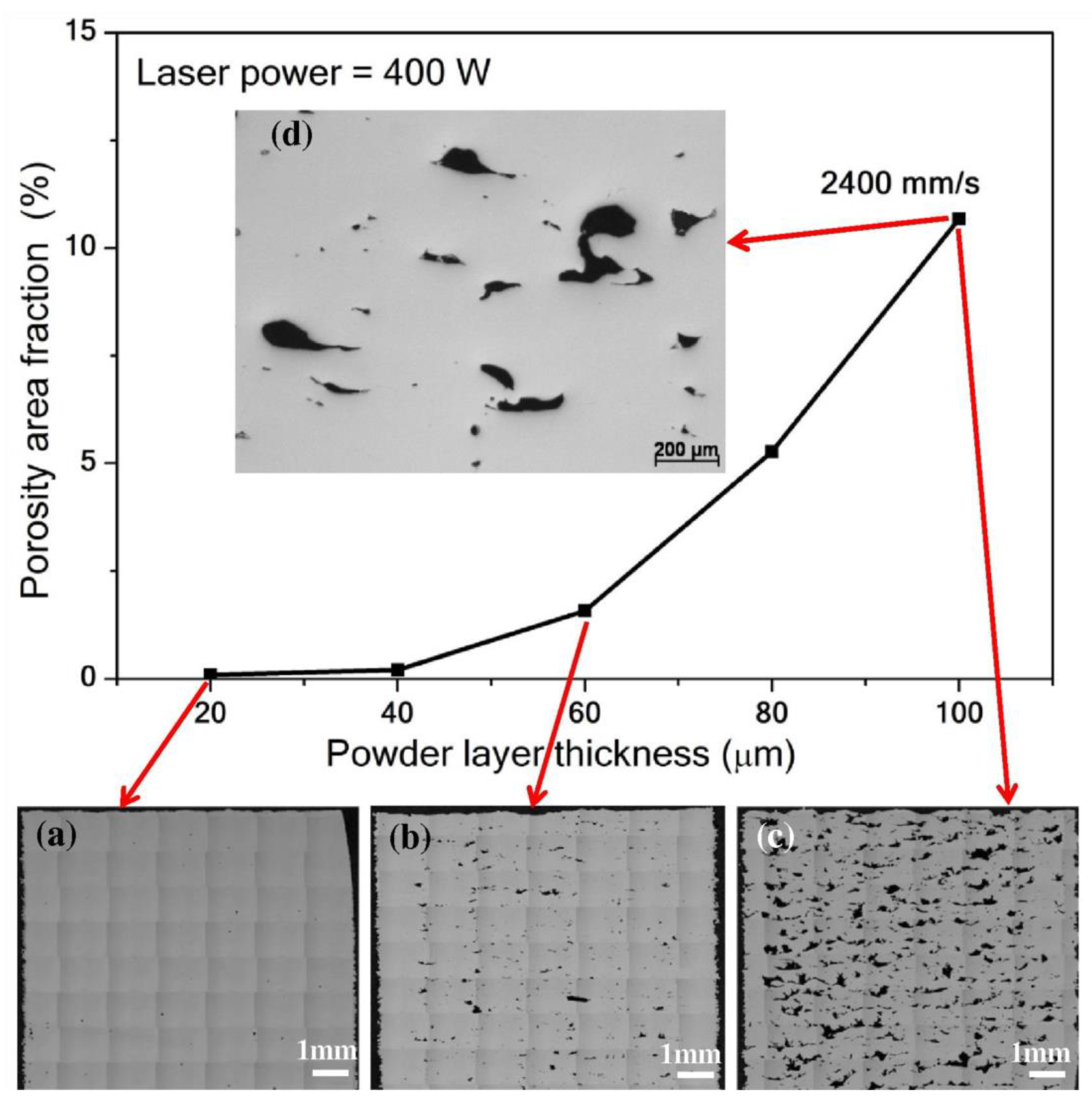
Figure 3.
Dissimilar accumulation of spattered particles [56].
Figure 3.
Dissimilar accumulation of spattered particles [56].
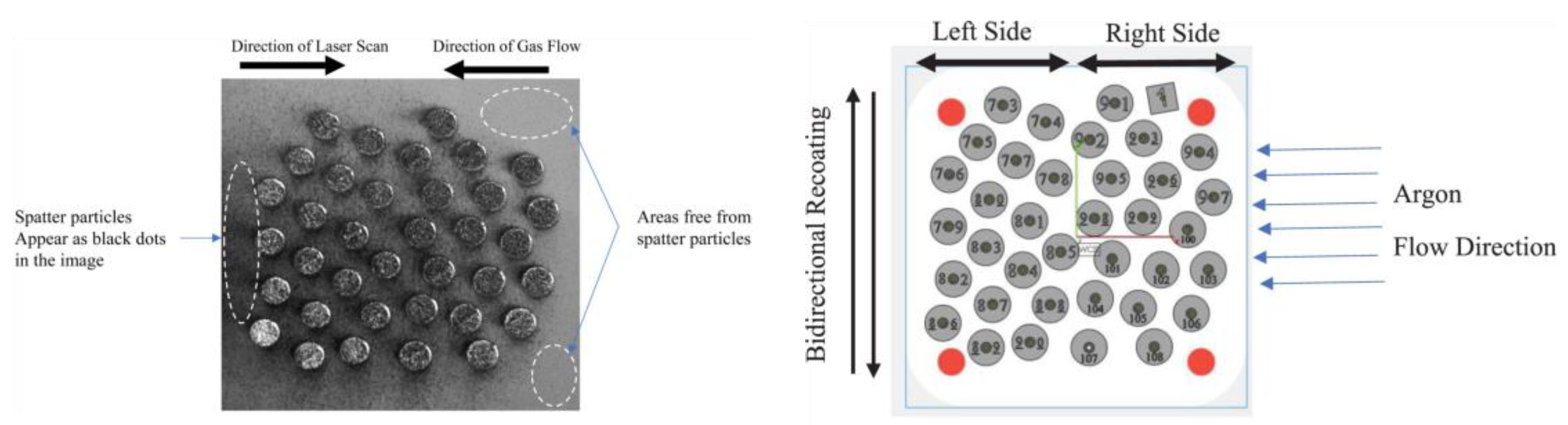
Figure 4.
Life cycle variation for left- and right-hand side specimens [56].
Figure 4.
Life cycle variation for left- and right-hand side specimens [56].
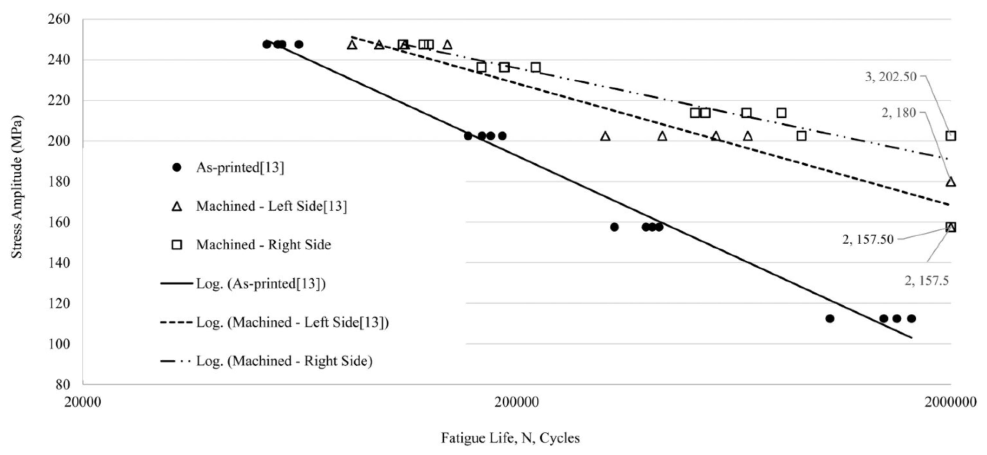
Figure 5.
Fatigue strength comparison of DMLS Ti6Al4V for different post processing method investigated by Mower Tet al. [99].
Figure 5.
Fatigue strength comparison of DMLS Ti6Al4V for different post processing method investigated by Mower Tet al. [99].
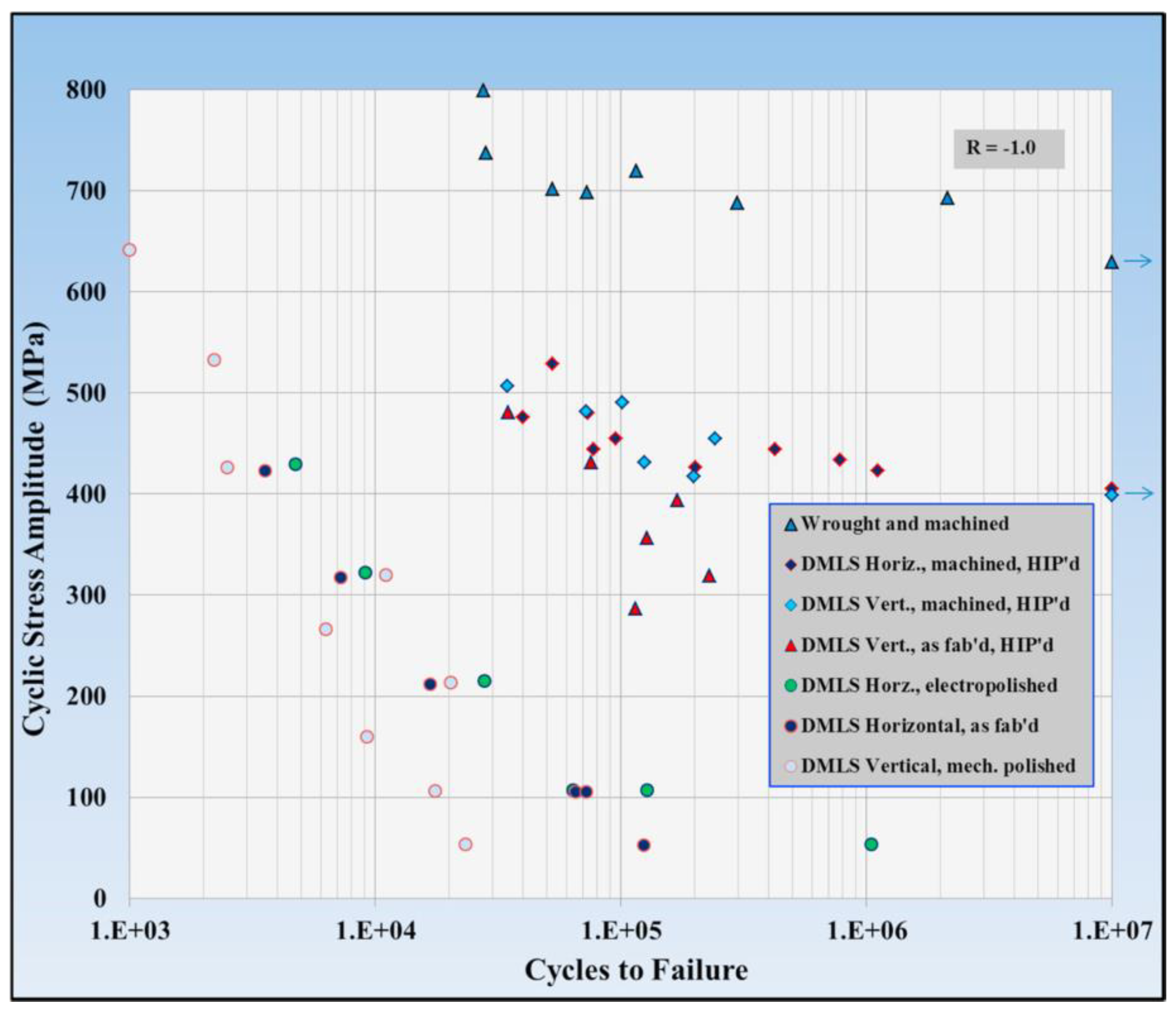
Figure 6.
Comparison of fatigue life in as built and polished specimens [100].
Figure 6.
Comparison of fatigue life in as built and polished specimens [100].
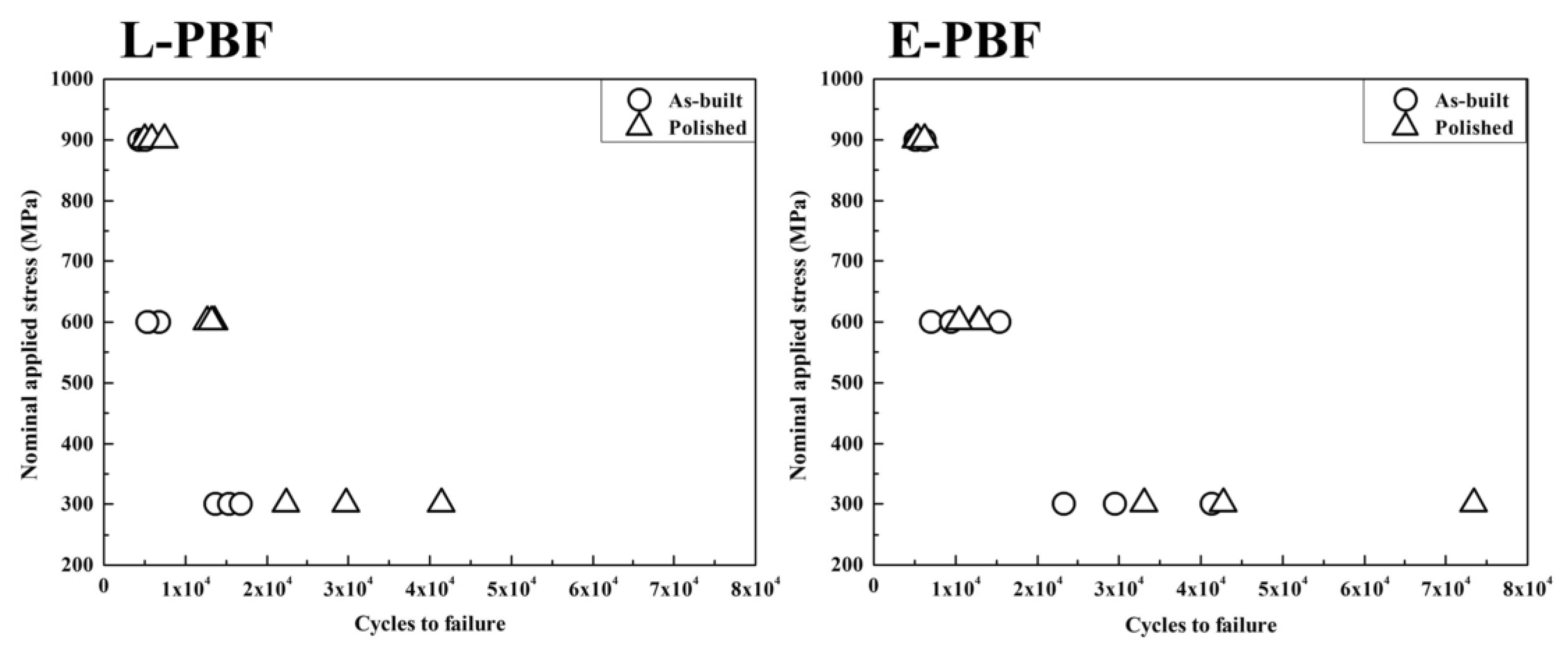
Figure 7.
Microstructural difference of Ti-6Al-4V before and after HIP [101].
Figure 7.
Microstructural difference of Ti-6Al-4V before and after HIP [101].
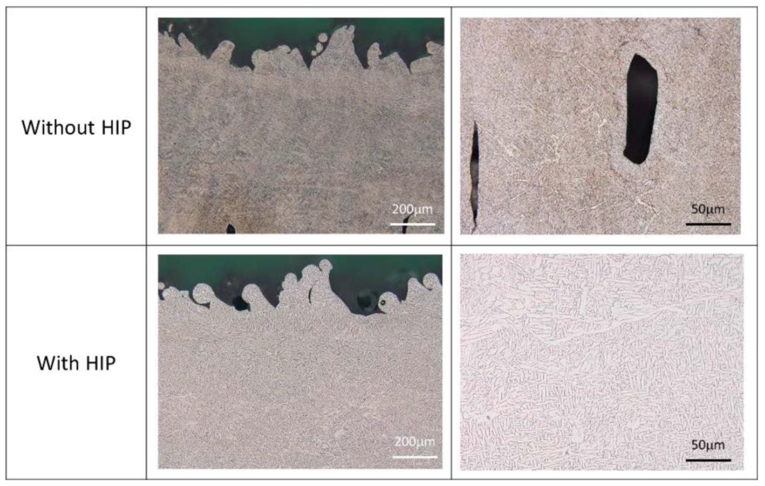
Figure 8.
Fatigue strength variation for Polished, HIP and without HIP specimens [101].
Figure 8.
Fatigue strength variation for Polished, HIP and without HIP specimens [101].
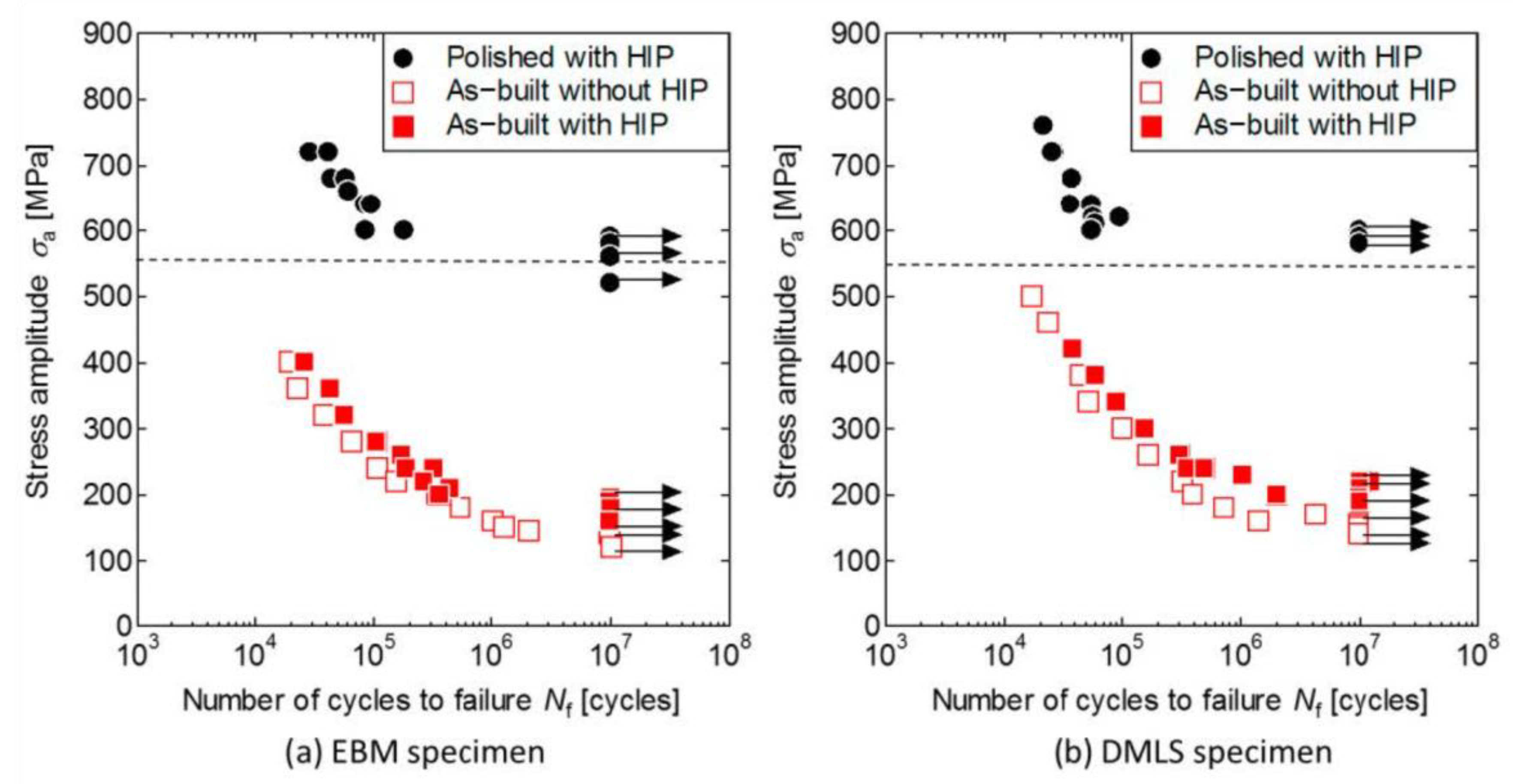

Table 1.
Variation of defects and porosity at different process parameters in LPBF produced Ti-6Al-4V fatigue specimens [52].
Table 1.
Variation of defects and porosity at different process parameters in LPBF produced Ti-6Al-4V fatigue specimens [52].
| Printing Parameter | Power (W) | Scanning Speed (mm/s) |
% Porosity | Circularity Avg. |
Number of Defects | Avg. dia. (µm) |
|---|---|---|---|---|---|---|
| P3 Keyhole | 370 | 800 | 0.385 ± 0.004 | 0.76 ± 0.04 | 3861 | 29 |
| P5 Process Window | 370 | 1400 | 0.106 ± 0.012 | 0.63 ± 0.06 | 1363 | 32 |
| P8 Lack of Fusion | 370 | 2000 | 0.215 ± 0.046 | 0.58 ± 0.05 | 2708 | 26 |
| EOS Nominal | 280 | 1200 | 0.008 ± 0.004 | 0.66 ± 0.06 | 231 | 22 |
| EOS Nominal Improved | 280 | 1200 | 0.017 ± 0.012 | 0.57 ± 0.05 | 143 | 19 |
Table 2.
Variation in surface roughness at different scan offset at same process parameters [52].
Table 2.
Variation in surface roughness at different scan offset at same process parameters [52].
| Nominal Contour Strategy | Improved Contour Strategy | ||||
|---|---|---|---|---|---|
| Contour 1 | Contour 2 | Contour 1 | Contour 2 | Contour 3 | |
| Contour Offset (micron) | 20 | 0 | 0 | 80 | 0 |
| Laser Power (W) | 150 | 150 | 100 | 100 | 100 |
| Scanning Speed (mm/s) | 1250 | 1250 | 450 | 450 | 550 |
| Surface Roughness (micron) | 15 | 7 | |||
Table 3.
Influence of AM process parameters on bending fatigue performance.
| References | Process parameters used | Materials Tested & process | Observed Defects/Surface Output | Bending Fatigue Performance | |||
|---|---|---|---|---|---|---|---|
| Laser Power | Scanning Speed (mm/sec) | Hatch offset, mm | Powder Particle Size/Layer thick, µm | ||||
| [52] | 370J, 280J | 800,1400, 1200,2000 |
Scanning direction altered | D10=26.4 µm, 55µm D50=37.2µm, 76µm D90=57.4µm, 106µm |
Ti-6Al-4V LPBF, EPBF |
Keyhole porosity, Lack of fusion porosity |
1. High laser power, low scanning speed affected fatigue life 2. Fatigue performance improved by optimizing scan strategy |
| [59] | 370 Watt | 1300 | 0.19 | LT=50, 80 µm, | AlSi10Mg LPBF |
1. 80µm layer caused larger LOF pores and high roughness, 2. 50µm has few and small defects |
1. 50µm showed higher rotating bending fatigue limit (70-80 MPa at 10^8 cycles compared to 80 µm (15-25MPa) |
| [60,61] | 370 Watt | 1350 | 0.09 | LT=50 µm | SS316L LPBF |
1. Lack of Fusion porosity with size 113 µm for pre corroded and 141µm for corroded specimen 2. Surface degradation with pronounced crevices and pits due to corrosion |
1. Corrosion bending fatigue test was performed. Pre-corroded specimens show about 20% reduction in fatigue life than the non-corroded one. 2. Fatigue strength was found for corroded and pre-corroded as 203 and 243 MPa respectively |
| [62,63] | 400Watt | Particle size = 40µm LT = 30µm |
Ti-6Al-4V SLM |
1. Gas pores, LOF pores 2. Anisotropic columnar grains |
1. Pores have a drastic effect on the fatigue behavior at high-cycle fatigue regimes. 2. Significant fatigue life variation between as built and heat-treated specimen due to removing residual stress. 3. Mean fatigue life increased from 27000 cycles to 93,000 cycles by stress relieving |
||
Table 4.
Effect of Build orientation of AM specimens on Bending fatigue performance.
| References | Build Orientation | Materials Tested | AM Process | Bending Fatigue Observation |
|---|---|---|---|---|
| [67] | 0°, 45° and 90° | Al2024-RAM2 | Laser Powder Bed Fusion (LPBF) |
1. 0° orientation showed lower roughness and the highest fatigue strength. 2. 45° and 90° had almost similar fatigue life as roughness was almost same. |
| [68] | 0°, 45° and 90° | Ti-6Al-4V | LPBF (SLM) |
1.Due to significant anisotropic characteristics, fatigue strength was reduced by around 40% when build orientation changed from 0 to 90 degree. 2. Favorable orientation was identified as 0° due to developing columnar grains against crack propagation thereby enhancing fatigue life. |
| [69] | Horizontal(0°) & Vertical (90°) | SS 17-4PH | Atomic diffusion AM (ADAM) | 1. Vertically oriented specimens experienced lower ductility and lower fatigue life than horizontally oriented specimens. 2. Vertically oriented specimens had poor quality with large pores due to lack of sintering that mainly extended towards the layer boundaries. |
| [70] | Flat, On edge and upright orientation | SS17-4PH alloy | Metal fused filament fabrication (MFFF) | 1. On-edge orientation displayed lower bending strength than flat orientation due to the creation of a sliding action by Poisson’s effect. This sliding action results in highly deformed and shifted voids towards the edge. 2. Upright orientation had higher bending strain and lower strength and limited plasticity as well. |
| [71] | Parallel (x-y) &perpendicular (x-z) | AlSi10Mg alloy | SLM | 1. At very high cycle fatigue (VHCF) regimes, the bending strength of the horizontally built specimens is higher than that of the vertically oriented parts due to microstructural effects while larger defect sizes were observed in the vertically fabricated parts. |
| [72] | X, Y and Z (Build direction) | Ti-6Al-4V | DED | 1. The mean fatigue life (logarithmic) in X and Y direction was almost twice that the fatigue life of the specimen built in the Z direction |
Table 5.
Effect of post processing on fatigue performance.
| References | Post processing/surface treatment applied | Material and Process | Type of fatigue test | Usefulness and improvements in fatigue performance |
|---|---|---|---|---|
| [92] | 1. Shot Peening (SP) 2. Laser shock Peening (LSP) 3. Centrifugal Finishing (CF) 4. Laser Polishing (LP) 5. Linishing (Lin) 6. Hot Iso-static Pressing (HIP) |
Ti-6Al-4V EPBF & LPBF |
Rotating Bending | 1. Fatigue life was increased by around 100-125% with CF, SP and Lin post processing compared to as built 2. Laser shock peening was observed increase fatigue life by around 5-20% 3. But laser polishing reduced fatigue life instead due to formation of high surface roughness 4. Stress relieved LPBF samples showed higher strength than EPBF HIPPED specimens |
| [93] | 1. Heat Treatment 2. HIP |
Ti-6Al-4V alloy, LPBF | Axial | 1. Fatigue strength was improved by three times when compared to as built by applying Heat treatment 2. HT+HIP increased fatigue properties by five times |
| [94] | 1. Machining 2. Hot Iso-static Pressing (HIP) |
718 alloy, EBM and SLM |
4-point bending | 1. Machined specimens had lower surface roughness and higher fatigue life, but large scatter observed due to large number of crack initiation sites. 2. HIP treatment significantly reduced the number of defects and improved fatigue life |
| [95] | 1. Vibratory polishing 2. Laser surface remelting (LSR) 3. Abrasive polishing |
Ti-6Al-4V &Inconel 625 EBM and SLM |
High Cycle Fatigue Test | 1. Both Vibratory and chemical finishing improved fatigue life by 3-5 times for Ti-6Al-4V 2. LSR and abrasive polishing didn’t improve fatigue life of Inconel 625 alloy significantly due to existing defects despite smoother surfaces |
| [96,97] | 1. Hot Iso-static Pressing (HIP) | Ti-6Al-4V LPBF DMLS |
Axial | 1. Internal defects can be minimized by HIP without affecting surface roughness 2. Fatigue life was decreased significantly with the increase of Arithmetic mean surface roughness |
| [98] | 1. Laser Polishing 2. Stress-Relief |
Ti-6Al-4V LPBF |
Fully Reverse Bending, R=-1 | 1. Laser polished specimens exhibited longer fatigue life cycle compared to as built by decreasing surface roughness due to remelting of the partially melted powdered particles. 2. Stress Relief process helped improve fatigue strength at low cycle zones |
| [99] | 1. Electro chemical polishing 2. Mechanical Polishing 3. Machined (Round specimen) 4. HIP |
AlSi10Mg SLM Ti-6Al-4V DMLS 316L &17-4PH |
Fully Reverse Rotating Bending, R=-1 | 1. SLM AlSi10Mg showed 60% higher strength than that of conventional Al6061 2. Post treatment process did not effectively enhance fatigue strength due to high number of defects, pores etc. 3. DMLS fabricated stainless steels showed 85%-95% of the fatigue strength of wrought steels 4. HIP process improved fatigue strength of DMLS 316L in the high cycle regimes only |
Disclaimer/Publisher’s Note: The statements, opinions and data contained in all publications are solely those of the individual author(s) and contributor(s) and not of MDPI and/or the editor(s). MDPI and/or the editor(s) disclaim responsibility for any injury to people or property resulting from any ideas, methods, instructions or products referred to in the content. |
© 2025 by the authors. Licensee MDPI, Basel, Switzerland. This article is an open access article distributed under the terms and conditions of the Creative Commons Attribution (CC BY) license (http://creativecommons.org/licenses/by/4.0/).
Copyright: This open access article is published under a Creative Commons CC BY 4.0 license, which permit the free download, distribution, and reuse, provided that the author and preprint are cited in any reuse.


