
Submitted:
17 September 2025
Posted:
23 September 2025
You are already at the latest version
Abstract
The perception of 3D space by mobile robots is rapidly moving from flat metric 1 grid representations to hybrid metric-semantic graphs built from human-interpretable 2 concepts. While most approaches first build metric maps and then add semantic layers, 3 we explore an alternative concept-first architecture where spatial understanding emerges 4 from asynchronous concept agents that directly instantiate and manage semantic entities. 5 Our robot employs two spatial concepts—room and door—implemented as autonomous 6 processes within a cognitive distributed architecture. These concept agents cooperatively 7 build a shared scene graph representation of indoor layouts through active exploration 8 and incremental validation. The key architectural principle is hierarchical constraint 9 propagation: room instantiation provides geometric and semantic priors that constrain and 10 improve door detection within wall boundaries. The resulting structure is maintained by a 11 complementary functional principle: prediction-matching loops. This approach builds an 12 actionable, human-interpretable spatial representation without relying on a pre-existing 13 global metric map, enabling scalable operation and persistent, task-relevant understanding 14 in structured indoor environments.
Keywords:
3D perception
; semantic modelling
; scene-graphs
; robot intelligence
1. Introduction
Robots designed to interact with humans in their usual places can benefit from a semantically rich, shared representation of their environment. In recent years, 3D scene graphs (3DSGs) have been used for this purpose, as complex data structures that represent scene objects as nodes and their various relationships as edges [1]. When used to describe large fragments of space, they are typically organised hierarchically, with higher levels encompassing larger spatial aggregations [2]. The computer vision community has developed many algorithms and DNN models that can be used to detect elements in the scene, their relationships, and even to build the graph directly from complete views of the scene [3,4,5]. Very complex graphs can also be built in real-time using data captured by a human-operated robot, as demonstrated in some recent frameworks [6,7]. In most experiments, robots are frequently used passively, in a remote-controlled setup, to capture 3D data in large environments.
However, if robots are to use 3DSGs in real-time operations, they must build them incrementally, starting from an empty representation when necessary, and proposing actions aimed at improving the current representation by reducing its uncertainty. These actions must coincide with or compete with other requests from other high-priority tasks, forcing the representational system to be opportunistic at its core. Scene graph construction should be driven by the robot’s need to understand its world and current task requirements. This opportunistic process may leave objects partially defined for later refinement, requiring the architecture to continuously update its world beliefs. This graph-building loop underlies the control architecture, adapting to ongoing tasks while competing for hardware access.
In this paper, we explore this view of 3DSG construction, where the robot decides what action to take next to improve or extend the current representation. We assume that the world is composed of rectangular rooms connected by doors. The robot is given a functional definition of the room and door concepts, and the goal is to incrementally build a scene-graph representation of the environment by instantiating these two concepts and relating the resulting instances in geometric and semantic ways. The graph is to be constructed directly from these concepts, avoiding a previous free/occupied grid representation. The robot has a 3D LiDAR that provides a stream of scene-measured points. Finally, we use the CORTEX architecture [8,9] as a robust and expandable framework for all the algorithms and data structures. Figure 1 shows a schematic overview.
Our first contribution is the idea of a concept process that sustains the life cycle of its instances, created to explain and predict objects of the world. A process for each concept runs asynchronously in the architecture and behaves opportunistically, contributing to building a global, shared representation. In turn, each concept accesses this representation to acquire a necessary context that constrains its creation and update process. Our second contribution is to develop an incremental, scene-graph building system designed for real-time operation in a mobile robot’s control architecture as an underlying representational dynamics adaptable to other concurrent tasks. Jointly, the concept processes and the other elements in the architecture collaborate to build and maintain a reliable scene graph that different tasks can use.
2. Related Works
2.1. From Geometric SLAM to Semantic and Hybrid SLAM
Classical geometric SLAM has been extensively studied and remains a cornerstone for robot localisation and mapping; however, its lack of high-level semantic content limits human–robot interaction, long-term robustness, and task-oriented reasoning [10,11]. To address these shortcomings, numerous works have proposed augmenting metric maps with semantic labels and object-centric landmarks, a family of methods commonly referred to as semantic or metric–semantic SLAM [12,13,14]. Other approaches tackle persistent mapping by emphasising the need for robust semantic reasoning in dynamic environments [15,16]. Similarly, CNN-based methods such as SemanticFusion [14] and Mask R-CNN extensions (e.g., PanopticFusion) [17,18] have made dense semantic mapping feasible in (near) real-time, bridging perception and mapping pipelines [19]. Surveys and overviews further summarise trends and techniques in this area, covering pipelines that combine detection, data association, and pose/landmark estimation [20,21]. Open-source libraries such as Kimera demonstrate the practical integration of visual–inertial SLAM, dense reconstruction, and semantic labelling to produce metric–semantic maps in real-time [22].
2.2. 3D Scene Graphs and Dynamic Scene Graphs
The idea of representing richer semantic and topological structure as a graph grounded in 3D geometry was crystallised by Armeni et al., who introduced the 3D Scene Graph (3DSG) as a unified hierarchical structure linking floors, rooms, objects, and cameras in reconstructed buildings [1]. Subsequent works have extended and operationalised this representation for robotics. Rosinol et al. introduced 3D Dynamic Scene Graphs (DSGs), emphasising actionable perception by adding temporal and agent-centric layers and presenting an automated spatial-perception pipeline to produce DSGs from visual–inertial data [22]. Hydra and related spatial-perception systems build on these ideas and demonstrate real-time 3DSG construction at scale, integrating segmentation, topological reasoning, and loop closure into an online pipeline [2,7]. SceneGraphFusion proposed an incremental, learning-based strategy to predict 3DSG from RGB–D sequences using graph neural networks and attention mechanisms suited to partial observations [3]. In parallel, Bavle et al. explored situational graphs as a lightweight, navigation-focused variant of DSGs, highlighting their role in bridging semantic scene understanding and actionable planning [23].
Within scene graphs, a first level of spatial structuring is provided by the layout of interior buildings, which condense the basic geometric structure of walls, floors, and ceilings. Their integration into a richer topological and semantic representation enables long-term reasoning and planning. More traditional approaches resort to the use of recognised geometric algorithms like RANSAC on the point cloud generated by SLAM to identify walls [24,25,26], similar to [27], where the Manhattan world assumption is added. Other works formulate layout reconstruction as an optimisation problem [28], resorting to mesh-based normalisation of input point cloud models and the subsequent use of a constrained optimiser. Their main advantage lies in their independence from large data sets and their geometric accuracy in well-structured environments, although they tend to be sensitive to hyperparameter tuning, occlusions, orthogonality assumptions, and sensor noise.
A distinct line of research leverages deep neural networks to infer complete room layouts from single panoramic images, with notable examples including LayoutNet [29], FloorNet [30], and HorizonNet [31]. These data-driven models exhibit strong generalisation capabilities and can produce geometrically coherent layouts at a low inference cost. However, from a robotics perspective, their utility is constrained by two primary factors. First, they are dependent on large-scale annotated datasets and often presuppose regular, structured environments. More critically, they operate as ’black-box’ systems performing a single-shot inference. This monolithic approach offers no mechanism for incremental refinement or reasoning about partial evidence. Consequently, these models struggle with the ambiguity inherent in a robot’s typical starting condition—often a position with limited visibility—a scenario where our concept-driven, hypothesis-validation loop is specifically designed to address.
2.3. Incremental, Opportunistic and Active Perception
While many 3D Scene Graph (3DSG) systems are validated on offline datasets, the robotics community increasingly demands representations that are built incrementally and refined through active perception for online operation. The principle of closing the planning–perception loop is well-established in Active-SLAM, where robot actions are chosen to reduce map uncertainty or gather task-relevant data [32,33]. This is complemented by information-theoretic approaches that provide principled methods for selecting optimal sensing actions under uncertainty [34,35].
More recent work on situational graphs frames scene understanding as the online construction of optimizable, multi-layer representations (metric, topological, semantic) for navigation [23,36,37,38]. Collectively, these research efforts motivate architectures where perception is not a passive aggregator of data, but an active process that deliberately seeks information to validate or refute semantic hypotheses—such as the existence of a room or the precise location of a door [33,39].
Our architecture embodies these principles by integrating affordances as context-sensitive controllers within each concept agent. These affordances are pre-activated when their operational preconditions are met. A central mission-monitoring agent executes tasks by selectively activating affordances that guide the robot toward its goal, interleaving these actions with others dedicated to constructing and maintaining the internal scene representation. This mechanism provides the foundation for the incremental, opportunistic, and active perception central to our system.
2.4. Open-Vocabulary and Language-Grounded Scene Graphs
Recent advances in vision-language models (VLMs) have catalysed a new generation of open-vocabulary 3D Scene Graphs (3DSGs), enabling robots to perceive and reason about an open set of objects and relationships. The dominant pipeline for these systems typically begins with class-agnostic segmentation of RGB-D frames, followed by the extraction and projection of semantic feature vectors into a common 3D frame. The resulting semantically-enriched point cloud is then processed, often with queries to a Large Language Model (LLM), to establish object identities and inter-object relationships.
While these methods demonstrate powerful capabilities for language-grounded querying, our concept-first architecture diverges from this paradigm in several fundamental ways, centred on the principles of incremental construction and the explicit modelling of environmental structure.
A primary distinction is our commitment to incremental, online construction without prior global maps. Systems like HOV-SG [40], for instance, require a complete metric map of the environment as a prerequisite for extracting floors, rooms, and objects. Navigation is then enabled by a permanent Voronoi graph of the total free space. In contrast, our approach builds its understanding dynamically as the robot explores. Navigation is handled locally on demand within the current room’s reference frame, while inter-room pathfinding is a simple graph search in the Long-Term Spatial Memory.
Furthermore, our architecture prioritises the explicit modelling of spatial structure and connectivity, whereas many open-vocabulary systems are fundamentally object-centric. Works such as Open3DSG [41] and OVSG [42] excel at establishing rich relationships among objects but do not acquire the containing room or the topological connectivity between rooms as first-class entities in the graph. Our work, conversely, treats the “room” concept as the primary semantic and geometric anchor, making the environment’s structure the backbone of the scene graph.
This focus enables our core principle of hierarchical constraint propagation, which is architecturally distinct from the bottom-up process common to many VLM-based pipelines. ConceptGraphs [43], for example, incrementally adds objects but must wait until an entire sequence has been processed to generate object captions and relationships. Spatial relations are estimated first by proximity and then refined by querying an LLM, a process that prevents high-level concepts (like a room’s walls) from actively constraining and guiding lower-level perception (like finding a door). Our top-down approach is designed around this very principle of semantic constraint.
Finally, while the field is advancing towards capturing object affordances and functional relationships, as pioneered by OpenFunGraph [44], our work provides the essential spatial-semantic scaffolding for such reasoning. OpenFunGraph masterfully models interactions between objects and their parts, but does not construct a representation of the surrounding spaces or validate that the graph remains anchored to the world as the robot moves. Our architecture is expressly designed to build and maintain this persistent spatial representation, providing the stable, grounded context in which functional and task-level reasoning can reliably occur.
2.5. Positioning of the Present Work
Most existing 3D scene graph construction approaches follow a metric-first paradigm: they build dense occupancy maps or point clouds, then layer semantic information on top through object detection and classification [3,6,7]. While effective, this approach conceptualises space primarily in terms of free/occupied regions—representations that enable collision-free navigation but provide limited support for high-level reasoning, manipulation planning, or human-robot communication. We explore an alternative concept-first architecture where spatial understanding emerges directly from human-interpretable concepts without requiring prior metric representations. Our approach makes four key departures from existing work: (i) asynchronous concept agents, rather than sequential metric-then-semantic processing, we implement concept classes (room and door) as autonomous processes that run asynchronously within the CORTEX cognitive architecture. Each concept agent manages the complete lifecycle of its instances —from initial detection through validation, maintenance, and execution of affordances— competing opportunistically for robot resources, (ii) hierarchical constraint propagation, where room instantiation provides geometric and semantic constraints that significantly improve door detection efficiency and robustness. Unlike unconstrained analysis of occupancy grids, doors are searched within the constrained space of validated room walls, leveraging spatial relationships inherent in indoor environments, (iii) world model of local metric frames where the global representation, managed by the Long-Term Spatial Memory (LTSM), is a topological graph connecting local, concept-centric metric frames. The robot localises itself relative to the current room’s frame, not a global world frame. This architectural pattern is a key distinction from systems like Hydra, which, despite their real-time performance, still ground a hierarchical scene graph in a global metric frame. Our contribution lies in exploring this alternative world model structure, which may offer benefits in scalability and human interpretability.
(iv) architectural vs. algorithmic contribution, as this work should be understood as an architectural exploration rather than an algorithmic one. We deliberately use simple and well-understood perception methods (e.g., Hough transforms) to focus attention on the organisational principles of the system. The core claim is not that our perception modules are state-of-the-art, but that an architecture of asynchronous, communicating concept agents can effectively build an actionable and persistent scene graph. While we currently focus on predefined concepts, we envision this architecture as a foundation that could be extended to synthesise the code of new concept agents using generative models.
3. Method
3.1. Architectural Motivation
Before describing the CORTEX implementation, we clarify our motivation for concept-first spatial representation. Traditional robotic mapping conceptualises space through the use of occupancy grids—binary free/occupied classifications that enable path planning but provide limited semantic content. While sufficient for navigation, these representations offer little support for: (i) human-robot communication—explaining robot decisions in terms of “occupied cells” rather than “rooms” and “doors”; (ii) high-level task planning requiring reasoning about functional spaces and their relationships; (iii) manipulation constraints—understanding that objects belong to rooms and inherit spatial constraints; and (iv) knowledge transfer—communicating spatial understanding between robots or to humans.
Concept-first representation addresses these limitations by grounding spatial understanding in human-interpretable entities from the outset. Rather than adding semantic layers post-hoc, the robot builds its world model directly through concept instantiation, enabling transparent reasoning about spatial relationships and their functional implications. The key insight is hierarchical constraint propagation: once a room concept is instantiated, it provides geometric boundaries (walls), functional relationships (containment), and semantic priors (door locations) that constrain and improve subsequent concept detection. This differs fundamentally from unconstrained analysis of metric data, where door detection must consider the entire perceptual field rather than focusing on geometrically and semantically relevant regions. This architectural principle naturally extends to future object detection —furniture constrained to floor planes, paintings to walls, or items to table surfaces— progressively narrowing search spaces through accumulated spatial context and reducing computational complexity while improving detection reliability.
3.2. The CORTEX Architecture
CORTEX is a cognitive robotics architecture initially designed to explore how the robot, the environment, and their interaction can be efficiently represented and anchored. A general scheme is shown in Figure 1. It is organised in two blocks: the cognitive level is a collection of specialised memories interconnected by processes named agents, which are responsible for pumping information among them, and the subcognitive level that maintains a bidirectional connection with the robot’s body. Additional details on the architecture can be found in [8,9,45].
The working memory (WM) depicted as a large green circle in Figure 1 is a distributed graph data structure implemented to provide very low latency and high throughput to a large set of connected processes that can edit it. The content represents the robot and its environment, which is built and maintained by specialised agents. Nodes in the graph represent objects in the world or the robot itself, and edges represent relationships among them that can be geometric transformations in SE(3) with uncertainty, called RT edges, or logic predicates. Agents run asynchronously, can edit the graph, and react to changes as part of their local goals. In the configuration used in this paper, the robot-body agent reacts to specific changes in the graph by controlling the robot’s movements. The mission-monitoring agent edits the graph to ensure a valid serialisation of the robot’s actions. Finally, the x-concept agents are pre-defined concept-aware processes that will attach to compatible objects in the environment. They have access to the subcognitive stream of perceptual data and try to explain out the parts of it that match their concept class (e.g., room or door in this case) by predicting it in the next step.
Figure 2.
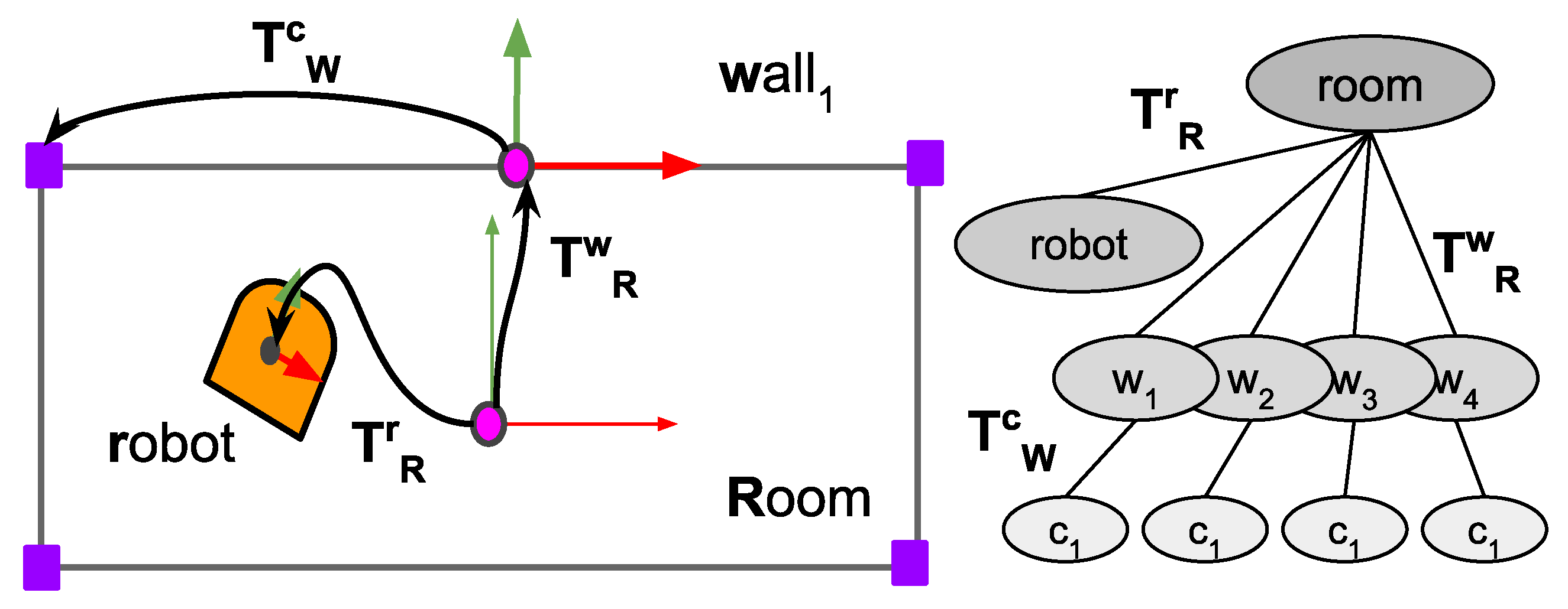
Reference frames used for the elements in the scene graph. On the left, the grey rectangle represents the model room that best fits the corners. denotes the transformation from the room to the wall, so a point p in the wall’s frame is transformed to the room’s frame as . On the right is the kinematic tree inserted into the WM.
Figure 2.
Reference frames used for the elements in the scene graph. On the left, the grey rectangle represents the model room that best fits the corners. denotes the transformation from the room to the wall, so a point p in the wall’s frame is transformed to the room’s frame as . On the right is the kinematic tree inserted into the WM.
3.3. Overview of the Spatial Representation Construction Process
The robot’s primary goal is to build an actionable scene graph representation of its environment through incremental concept instantiation and validation. This process involves several asynchronous agents, primarily and , that cooperatively construct a shared spatial model within the Working Memory (WM), supported by the robot_body, energy_optimiser and long_term_spatial_memory agents, and orchestrated by the mission_monitoring agent.
The representation construction follows a concept-first paradigm where spatial understanding emerges from the instantiation and anchoring of semantic entities rather than from metric grid mapping. The robot begins with no prior spatial knowledge and bootstraps its understanding through active exploration. Upon initialisation or after crossing a door, the agent attempts to instantiate a room concept by detecting corners in the 3D LiDAR point cloud . Successfully instantiated rooms become reference frames for subsequent spatial reasoning, with the robot’s pose continuously updated relative to the current room through factor graph optimisation.
For this initial exploration, we adopt the Manhattan world assumption—rooms are rectangular with orthogonal walls—which simplifies geometric reasoning while remaining applicable to many real-world indoor environments. Each room maintains a centre-based coordinate frame with child frames for its four walls, forming a kinematic tree that structures spatial relationships. Doors are constrained to lie within wall boundaries, with at most one door per wall, connecting exactly two rooms.
The concept lifecycle encompasses detection, initialisation, validation, and maintenance phases. During initialisation, concept agents propose intentional actions (e.g., navigating toward a room’s estimated centre or to a vantage position in front of a door) to gather sufficient observational evidence. These actions are mediated through has_intention edges in the WM, requiring approval from the mission_monitoring agent before resource allocation. The initialisation process accumulates measurements across multiple robot poses, building temporal pose graphs that resolve geometric ambiguities through optimisation. Once sufficient evidence confirms adherence to concept priors, instances transition from provisional to permanent status in the WM. Figure 3 shows an example of a structural modification in the scene graph. The transition occurs when a room is detected, initialised and inserted into the graph, causing the robot node to change its parent. The new RT edge is now updated by the energy_optimizer agent, minimising the differences between measured and nominal features.
Critical to this architecture is the synchronisation achieved through graph-based communication. The agent remains dormant until a current room exists in the WM, ensuring doors are always grounded within validated spatial contexts. This hierarchical dependency —doors require rooms, rooms enable localisation— creates a natural ordering that prevents premature or unconstrained concept instantiation. Similarly, the energy_optimiser agent continuously monitors the WM for validated corner and door measurements, incorporating them as landmarks in its localisation factor graph only after concept agents confirm their validity through successful matching against predictions.
The architecture explicitly acknowledges operational boundaries. Severely cluttered environments where furniture occludes wall geometry, non-rectangular spaces that violate Manhattan assumptions, or dynamic scenes with moving obstacles may challenge successful concept instantiation. Rather than attempting exhaustive coverage of edge cases, the system maintains probabilistic beliefs and can defer instantiation when evidence remains insufficient. Despite this cautious approach, the current implementation faces two critical failure modes: false positives, where incorrect models satisfy the validation criteria and become accepted as valid representations, and model invalidation, where initially correct models become inconsistent as additional exploration reveals previously unobserved geometric features. We are developing backtracking mechanisms to revert to previous stable states when model confidence degrades, as well as dynamic restructuring capabilities to adapt existing representations when new evidence contradicts established beliefs. This work is discussed further in the Conclusions and future works section. The mission_monitoring agent can interrupt ongoing initialisation processes to pursue higher-priority goals, leaving partial representations for later refinement. This opportunistic approach allows the robot to build useful, if incomplete, spatial models while remaining responsive to task demands.
Through this distributed, asynchronous process, the robot incrementally constructs a scene graph that directly supports navigation, manipulation planning, and human communication without requiring intermediate metric representations. The resulting graph maintains both geometric precision (through continuous localisation) and semantic richness (through concept instantiation), providing an actionable spatial model grounded in human-interpretable entities.
3.4. Conceptual Agents and Intentional Actions
A conceptual agent is an autonomous process responsible for the instantiation, maintenance, and refinement of a specific concept class , where denotes the set of all concept classes manageable by the robot (e.g., ). Each concept class is defined as a tuple , where:
- is the set of measurable properties that define the geometry of the concept (e.g., height, width, centre, corners, anchor points, etc.).
- is a set of prior values over the properties that determine when a new instance is created. (e.g., height to width ratio).
- is the set of affordances associated with the concept. In this case, the affordances are visit for the room and visit and cross for the door. The visit intention is notified to the mission_monitoring agent with the insertion of a has_intention edge in the graph, while the cross affordance is notified with the creation of a special node aff_cross_x hanging from the associated door. If the affordance is accepted by the mission_monitoring agent, the robot_body agent executes the action until completion.
- is the initialisation process for a new instance candidate.
- is the life cycle of the concept instances, defined as a behaviour tree that monitors and controls the transitions between internal states.
The lifecycle ( ) is implemented as a behaviour tree that continuously orchestrates four primary stages of concept instance management, see Figure 4. First, the agent evaluates whether existing nominal instances in the WM can explain incoming sensor measurements through forward prediction and matching. When sensor data cannot be adequately explained by current instances (matching error exceeds threshold), the initialisation process ( ) is triggered, accumulating evidence through intentional actions until sufficient confidence permits instantiation of a new nominal element in the WM. For established instances, the agent maintains their validity by computing predicted feature positions based on current robot pose estimates, enabling these predictions to serve as landmarks for robot localisation through the energy minimisation process. Concurrently, when affordances are active, the agent monitors their execution status through the robot node, tracking action progress until completion or interruption by the mission monitoring agent. This cyclic process ensures that concept instances remain grounded in sensory evidence while providing stable reference frames for navigation and supporting opportunistic exploration through affordance execution.
3.4.1. Room-Concept Agent
implements the room concept class. The class provides a parameterisation of a room in terms of centre, angle and dimensions, , as well as the equivalent description by its corners . Room instances are actively searched when the robot starts or when a door is crossed. As explained in the next subsection, previously known rooms are recovered and inserted into the WM asynchronously by the long-term spatial memory agent.
Room corners are detected using a simple but efficient method shown as Algorithm 1. This algorithm, along with the door detection method presented later, does not represent state-of-the-art (SOTA) performance but provides a sufficient baseline for demonstrating the proposed architectural principles.
The algorithm begins by (1) filtering the 3D LiDAR field P to retain only those points within a vertical slice defined by reducing noise from floor and ceiling artifacts; (2-5) the mean and covariance matrix are computed to estimate the room centre and room’s dimensions ; (6) a Hough Transform is applied to extract structural lines; (7) candidate walls are retained if their lengths exceed a threshold ; (8,9) all pairs of lines are checked for angle crossings to select candidate corners . The algorithm returns a list of corners.
| Algorithm 1:Corners Detector Algorithm |
|
The agent continuously runs the corner detection algorithm. When a set of detected corners satisfies the instantiation conditions , and there is no room object in the WM already, the agent inserts a temporary room node into the WM, linked to the robot node via a has_intention relation. Upon approval by the mission-monitoring agent, computational and physical resources are allocated, and the robot initiates a navigation action toward the estimated centre of the room, computed as the centroid of the currently measured corner points. This action develops locally in the robot’s frame.
At the beginning of the action, the robot’s position is taken as the initial zero frame. As the action proceeds, new poses are concatenated using the odometry readings from the robot’s sensors and stored in a local buffer. The measured corners are also stored in the current robot frame. When the action is completed, the concept agent evaluates whether the accumulated data is sufficient; if so, it initiates a post-processing phase. Otherwise, sampling continues from the new vantage point. The mission-monitoring agent can revoke the affordance at any time.
As no external frame is available, the agent builds a temporal pose graph into the GTSAM1 framework with the data accumulated during the action. The measured corners take the role of landmarks, and since they are seen from several robot poses, the graph acquires the necessary redundancy. The optimal graph that minimises the sum of prediction errors provides a set of corrected landmarks and poses. From the set of corrected corners’ poses, a histogram is built to select a subset of the most probable corners that comply with the room constraints. The concept agent applies at this point additional priors to the potential candidates to discard rooms that are too large or too small.
The process ends with the insertion of the room into WM, along with its walls and corners, and an RT edge anchoring the robot to the room. This last step requires some elaboration since a rectangle does not have an intrinsic orientation. The temporal pose graph was anchored to the action start pose. The selected set of corners has coordinates in that frame, and the robot occupies now the last pose of the graph. With these data, we want to set the room frame as the zero initial frame and compute the pose of the robot with respect to it. A simple solution is to take the position and size room parameters from the selected corners, and compute the rotation, or equivalently, an enumeration of the corners that assigns index zero to the first corner to the left of the robot heading direction.
3.4.2. Door-Concept Agent
The agent controls the life cycle of instances belonging to the door concept class. Doors are parametrised in as pairs of anchor points defining the door ends. They have two affordances : visit and cross. is the range of admissible distances between the anchor points, currently set to meters.
We propose a simple door detection algorithm, shown in Algorithm 2. It begins by (1) assuming that doors lie within the walls W of the room and filtering out any point whose distance to the walls exceeds a predefined threshold ; (2) extracts a polar 2D scan , where is the measured distance for each angular value at a fixed height index , in our experiments; (3) takes the derivative to identify abrupt changes in the distance dimension; (4) applies the Heaviside step function H to yield a binary peak map where a value of 1 indicates a potential edge and zero otherwise; (5) computes all combinations of pairs of detected points; (6) each candidate is tested against the width constraint and the wall constraint that ensures that the line segment lies within the set of wall points; (7) returns the set D of valid detected doors.
| Algorithm 2:Door detector algorithm |
|
When the current room is detected in the WM, the agent starts running the door detection algorithm. It silently returns if existing nominal doors can explain all the pairs of anchor points detected in the point cloud. When a new door is detected, a process similar to the one described before starts, but with some differences. A provisional door, labelled as door_x_pre, is inserted into WM hanging from its containing wall, and a has_intention edge is inserted between the robot and the door. Figure 7 shows how these changes occur in the scene graph.
Once the mission_monitoring agent assigns resources, the visit affordance is executed by the robot_body agent. The robot navigates towards a point located from the door’s centre. But now the robot is being localised in the room’s frame by the energy_optimiser agent running a global optimisation over the scene graph. To benefit from this situation, the agent only updates the matching between the measurements and the provisional anchor points and waits for the end of the action. The energy_optimiser agent recognises those objects as landmarks and includes them in the minimisation. When the action finishes, the fine-tuned anchor points are set as permanent, and their nominal coordinates are computed and inserted in the RT edge connecting the wall to the new door. The door name is changed to door_x, removing the pre suffix. The nominal door now provides its two anchor points as additional fixed landmarks to the energy_optimiser agent to update the robot’s pose in the room. Finally, a node connected to the door with an has edge is added to show that a cross affordance is available for the mission_monitor agent to include in its planning logic.
3.5. Long-Term Spatial Memory
In CORTEX, the Long-Term Spatial Memory (LTSM) stores previously visited rooms and their connections via doors. This information is maintained in a persistent graph data structure using the igraph library2. The agent operates asynchronously over the WM, removing visited rooms when the robot has entered and initialised a new one, and bringing (i.e., predicting) back known rooms when the robot is about to enter a previously explored one. The precise timing of these actions is explained below.
When the robot enters an unfamiliar room, it needs to retain some information about the room it is leaving until a reliable connection can be made between the two. The agent stores doors as dual objects with coordinates in both rooms’ frames. This is the minimal information needed to maintain an actionable graph of connected rooms. As the agent observes the crossing, it waits until the new room is initialised following the procedure described before, and only then sets the new room as the current room and removes the old one from the WM. The required synchronisation is done through the edition of node attributes and edges in the WM, since this is the only way for agents to communicate.
The insertion of a known room is simpler since this agent is anticipating what will see. The critical variable is the orientation of the new room with respect to the robot, since the success of the corner matching process, which determines its acceptance, will depend on this. The information is taken from the door dual coordinates. The new room is oriented by first transforming its corners to the door’s coordinate frame. Then, we identify both door frames as being at the same point in space, and use this to transform the corners back to the old room’s coordinate frame and, finally, to the robot’s frame. In this way, the robot can match the new room’s nominal corners with fresh measurements since both are in the same frame, and confirm the recognition of the new room. Hereafter, the old room is removed, and the robot is changed in the scene graph to hang now from the new room.
Figure 5 shows a metric representation of the rooms in the four-room scenario, with the rooms the robot has previously traversed shown in green, and the room it is currently located in shown in red. Additionally, a green dot indicates the target position the robot is heading towards after crossing the door. The agent can create a metric representation of the graph at any time, as shown in the bottom-left image. The evident alignment errors are due to noise injected in the synthetic LiDAR sensor and the robot displacements, and could be corrected with a constrained optimisation of the rooms’ centres, sizes, and orientations, where the doors act as fixed, shared points between them. Still, it is left for future work since it does not interfere with the goals of this paper. The red circle on the right shows the result of a loop closure between rooms 1 and 4 through their shared door. Currently, the LTSM agent computes a loop closure by projecting the robot’s pose in all rooms when it is about to enter a new one. A more robust method based on visual descriptors and the objects stored in the room is under construction.
3.5.1. Scalability Through Hierarchical Memory Organisation
The LTSM component addresses a fundamental scalability challenge in robotic spatial representation: maintaining complete world models in active memory becomes computationally prohibitive as environment size increases. The CORTEX architecture’s memory organisation provides several mechanisms that enable operation in arbitrarily large environments while preserving real-time performance. First, the architecture employs dynamic memory management based on the principle that robots require detailed spatial representations only for their immediate operational context. As the robot navigates multi-room environments, the LTSM dynamically loads rooms into working memory based on current location and planned actions, while unloading distant or irrelevant spaces. This selective memory management maintains bounded computational requirements regardless of total environment size, enabling real-time operation in large-scale facilities such as office buildings, hospitals, or multi-floor residential complexes. Second, the LTSM maintains persistent topological graphs representing complete known environment structures, stored using the igraph library. These graphs naturally accommodate arbitrary environment topologies—from linear corridor sequences to complex branching structures with multiple floors, wings, and interconnected spaces. Third, the memory architecture supports hierarchical spatial organisation, with concepts extending beyond individual rooms. Spaces can be organised into floors, buildings, or functional regions (e.g., “residential wing,” “laboratory area”). This hierarchical organisation enables efficient navigation planning across multiple scales while maintaining the human-interpretable structure that motivates the concept-first approach. High-level spatial queries can be resolved at appropriate abstraction levels without requiring detailed geometric computation. And fourth, context-dependent predictive loading activates when the robot approaches transition points (doors leading to known rooms) and anticipates spatial context requirements by pre-loading relevant representations. This includes not only the target room’s geometry and contained objects, but also connected spaces that might become relevant for navigation alternatives or task planning. This predictive loading strategy ensures smooth spatial transitions while minimising working memory overhead and maintaining responsiveness.
The combination of these mechanisms shows that concept-first spatial representation scales effectively beyond individual rooms to support large-scale robotic operation. The hierarchical memory organisation maintains both computational efficiency and human-interpretable spatial structure, addressing scalability concerns while preserving the transparency and explainability advantages of the concept-driven approach.
3.6. Navigating Through the Scene Graph
Once a nominal current room is established, the energy-optimiser agent updates the robot’s position at a fixed frequency of 10 Hz. This agent maintains a GTSAM factor graph. It is initialised with the nominal room corners and the robot’s pose in the WM. As fresh odometry data arrives from the robot sensors, the agent inserts new robot poses into the graph up to 30 nodes, applying a FIFO policy. The sliding window version of iSAM2 in GTSAM computes the optimal robot pose after the graph modifications, considering the required changes in the covariance matrix.
At each insertion of a new robot pose, the energy-optimiser agent verifies if there are measured corner values in the WM that the corresponding concept agent has validated. Validation results from a matching process between the projection of the nominal corner on the robot’s frame, and the current measurement. We use the Mahalanobis distance to match the corners weighted by the covariances of the measurement and the uncertainty contributed by the current robot pose. The validation is determined by inspecting a Boolean attribute stored in the corner measurement node within the WM. Figure 6 shows how all these elements are related as a factor graph.
If a corner has been validated, it is incorporated into the factor graph as a measurement associated with its corresponding landmark. This measurement is connected to the pose node whose timestamp most closely matches that of the corner observation. Similarly, if a door has been instantiated in the WM, its nominal position is inserted into the graph as a landmark. Door measurements are handled analogously to corner observations.
4. Results
We have designed a series of experiments to evaluate the architecture using the Webots simulator. The scenarios include a digital replica of our Shadow mobile robot [46], with realistic white noise added to the synthetic LiDAR and delays in command execution.
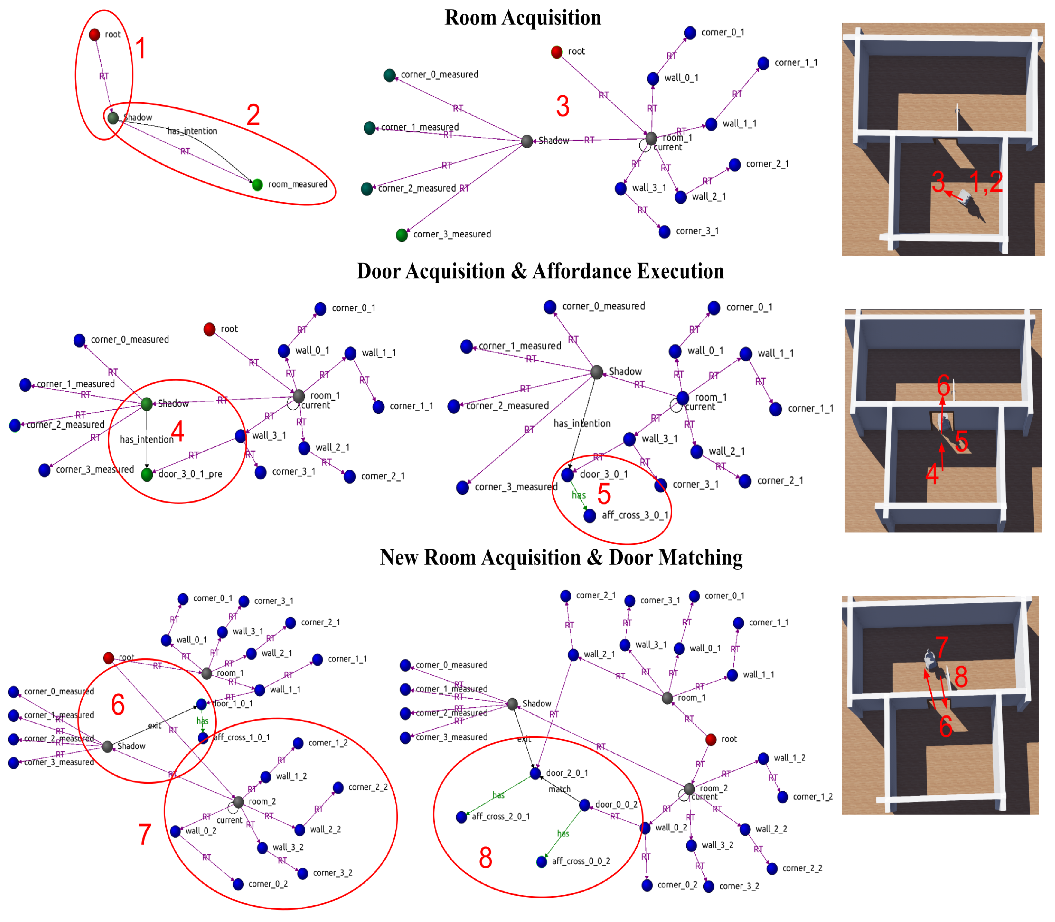
A first experiment, Figure 7, shows the three main stages in the evolution of the scene graph within the WM. Red circles denote interest zones referenced in the text.
Figure 7.
Main stages in constructing the scene graph during exploration, reflecting transitions as different concept instances are initialised and affordances are executed. See text for a detailed explanation.
Figure 7.
Main stages in constructing the scene graph during exploration, reflecting transitions as different concept instances are initialised and affordances are executed. See text for a detailed explanation.
-
Room acquisition: Following the sequences shown in Figure 7 as red ellipses, in Zone 1, the robot lacks a room representation. The agent is aware of the absence of a room node and starts the initialisation process. This is reflected in the WM by the appearance of the link between the robot Shadow and room_measured, Zone 2. The waits until the mission_monitoring agent authorises the action.When the robot reaches the room’s centre or sufficient data are gathered, the agent inserts the room into the graph. The coordinate frame changes during this transition, and the robot’s pose is expressed relative to the room’s reference frame. This relationship is captured by the link between the room and the robot, as shown in Zone 3. From now on, this link is updated by the energy_optimiser agent performing a continuous optimisation over the room’s corner observations.
- Door acquisition and affordance execution: With a current room established in WM, the agent can now proceed with detecting doors. Zone 4 shows a new door proposal door_3_0_1_pre and an action proposal in the edge has_intention. The robot moves close to the door and the agent changes the door status from provisional to acquired, removing the pre suffix. Additionally, the agent inserts an affordance node aff_cross_3_0_1 hanging from the new door to notify the mission_monitoring of that action’s availability. This is shown in Zone 5.
- New room acquisition and door matching: The execution of the door-crossing affordance, Zone 6, takes the robot into a new room, triggering a second initialisation process. On completion, the agent inserts a new room node room_2 and its constituent elements into the graph, Zone 7. If the room had been previously known, the LTSM agent would instead load the stored room, bypassing the initialisation step. Zone 8 illustrates how doors are associated across rooms immediately before the LTSM agent removes the previously visited room and sets the new one as the current. At this point, the door gets the dual coordinates that place it in both rooms. The LTSM agent maintains a local graph representing all known spaces and the open transitions between them, while removing and loading rooms as the robot explores its environment.
A second experiment demonstrates a more extended activity within a ten-room scenario. Following the steps described in the previous experiment, the robot incrementally builds its internal local and global representation, and at one point, it closes a loop connecting several rooms. A video of the full experiment can be downloaded from this site 3. All agents and the components in the sub-cognitive module run in different cores of the onboard computer, an Intel i9 13th generation processor with an NVidia RTX-A2000 GPU, and can sustain the nominal sensor acquisition rates, 20Hz for the 3D LiDAR and 30 HZ for the 360º camera.
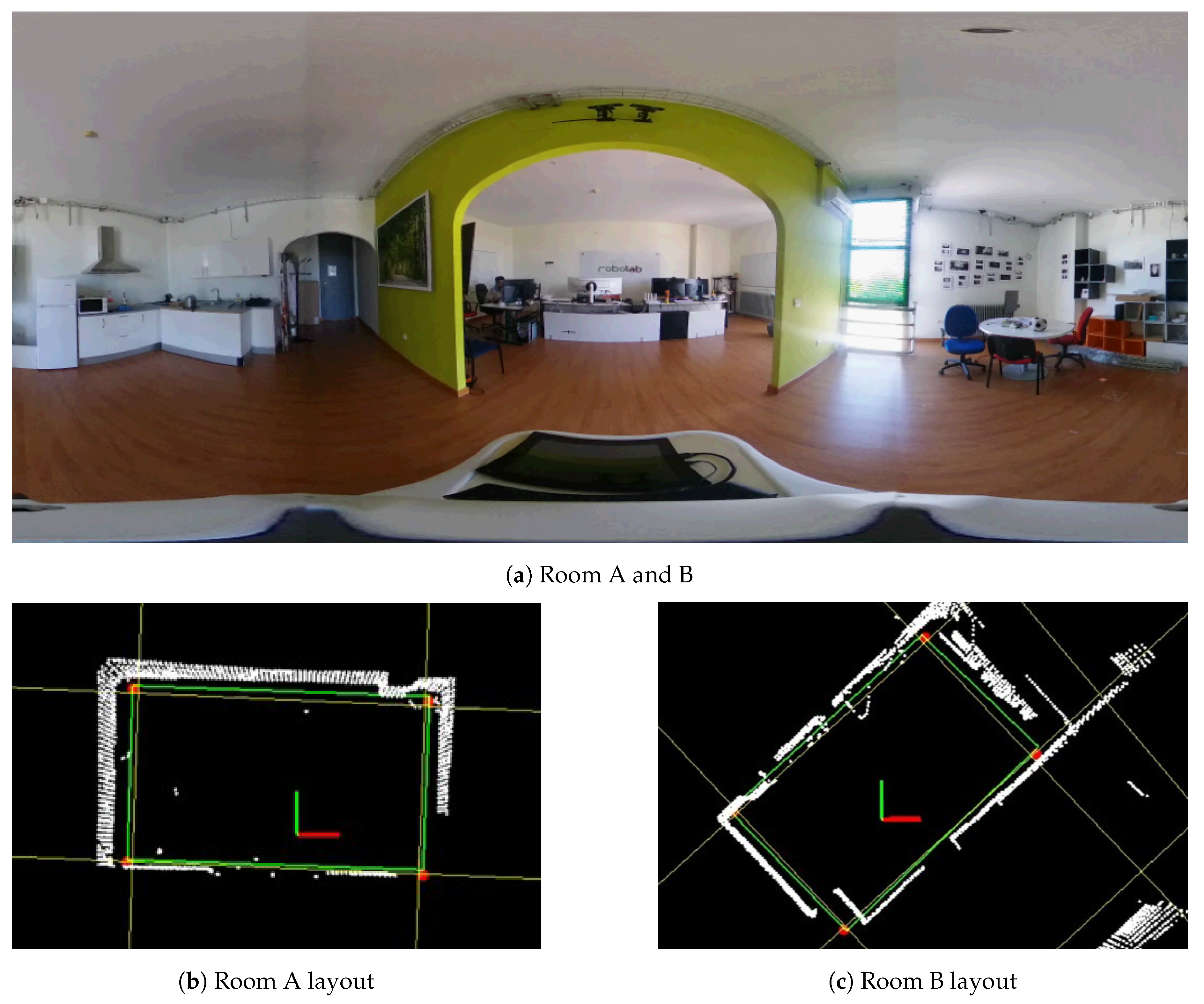
The third experiment places the robot Shadow in a real scenario, navigating between two rooms separated by a door. Figure 8 shows the two rooms with their usual furniture and the room layouts extracted from them. Note that processing only the upper part of the 3D LiDAR field, , eliminates most of the non-wall points, and the large structures detected with the Hough lines provide enough information to complete the correct layout. We are exploring ways of removing more of the remaining points that do not belong to the walls, for instance, by filtering the 3D point cloud with a semantic segmentation DNN. The robot has remained located with respect to the rooms’ frames for four-hours navigation sessions, with maximum positioning errors of 15cm.
5. Noise Sensitivity and Detection Mistakes
The robustness of concept-first spatial representation depends critically on reliable feature detection and consistent model validation. Two primary failure modes affect the current implementation: sensitivity to sensor noise and detection mistakes that manifest either immediately or after additional exploration.
5.1. Noise Sensitivity
The quality of the final spatial representation degrades with increasing sensor and odometry noise. While systematic evaluation of noise sensitivity requires extensive parametric studies (planned for future work), preliminary observations from our simulations reveal several noise-related challenges. LiDAR noise affects corner detection reliability, particularly when points near wall intersections are displaced beyond the algorithm’s clustering threshold. Similarly, odometry drift compounds during the initialisation phase, potentially causing misalignment between the selected corner set and the actual room geometry. The GTSAM optimisation partially mitigates these effects by distributing error across the pose graph, but significant noise levels can lead to incorrect room models being accepted as valid.
Future work will quantify these relationships through controlled experiments varying: (i) LiDAR point cloud noise (m to m), (ii) odometry drift rates ( to of distance travelled), and (iii) angular measurement uncertainty ( to ). The expected outcome is a noise tolerance envelope within which the concept-first approach maintains acceptable spatial accuracy.
5.2. Detection Mistakes and Model Revision
The current lifecycle implementation assumes that once validated, concept instances remain fixed. This rigid approach fails to handle two critical scenarios that occur in practice:
Early Model Mistakes: Despite the validation process, incorrect models may satisfy the instantiation criteria due to partial occlusions, symmetric ambiguities, or sensor limitations. For example, a large L-shaped space might initially be interpreted as a rectangular room when only one branch is visible. The current architecture lacks mechanisms to revise these early commitments when contradictory evidence emerges.
Temporal Model Invalidation: Initially correct models may become inconsistent as exploration reveals previously unobserved features. A room model validated from limited viewpoints might prove incompatible with newly discovered walls or openings. Without dynamic revision capabilities, these inconsistencies accumulate, degrading the overall representation quality.
Addressing these limitations requires extending the concept lifecycle with continuous model fitness evaluation and revision mechanisms. We envision a more flexible lifecycle incorporating:
- Continuous Fitness Monitoring: Each concept instance maintains a running fitness metric quantifying the agreement between predicted and observed features. This metric would track both recent observations (for rapid response) and historical consistency (for stability).
- Graduated Response Strategy: When fitness degrades below threshold, the system would engage a hierarchical response: (i) local parameter adjustment for minor discrepancies, (ii) structural revision for significant geometric changes, and (iii) complete model replacement when the current instance becomes untenable.
- Backtracking and Alternative Hypotheses: The architecture would maintain alternative concept instantiations as latent hypotheses, enabling rapid switching when the primary model fails. This requires extending the concept-agents to support probabilistic beliefs over multiple competing interpretations. A particle filter would be a good starting point.
- Graceful Degradation: When no satisfactory model exists, the system should maintain partial representations rather than forcing incorrect instantiations. This might involve temporary metric patches or undefined regions marked for future exploration.
These extensions would transform the current deterministic lifecycle into a probabilistic framework where concept instances compete, evolve, and occasionally fail. While computationally more demanding, this flexibility is essential for robust operation in real-world environments where perfect sensing and complete observability cannot be guaranteed.
6. Conclusions and Future Works
This work presents an architectural exploration of concept-first spatial representation for mobile robots. By implementing room and door concepts as asynchronous agents within the CORTEX cognitive architecture, we demonstrate that semantic scene graphs can be built incrementally without requiring prior metric maps. The key innovation is hierarchical constraint propagation, where room instantiation provides geometric and semantic priors that improve door detection efficiency and robustness compared to unconstrained metric analysis. While our current implementation is limited to rectangular rooms in structured environments, the architectural principles—asynchronous concept agents, direct scene graph construction, and hierarchical constraint propagation—extend naturally to more complex spatial concepts and irregular geometries. The use of simple detection algorithms (Hough transforms, gap analysis) reflects our focus on architectural rather than algorithmic contributions; more sophisticated perception methods would enhance system performance while preserving the core organisational principles.
This work leaves many open research topics, most of which are already under way: a) extending the system to handle non-rectangular rooms; b) replacing room and door detection algorithms with more robust data-driven learnt functions; c) using differentiable programming in the characterisation of object geometries so they can be adjusted online through the minimisation of a cost function; d) incorporating additional concept classes (e.g., furniture, household objects) into the scene graph; e) and implementing a more robust loop closure mechanism based on visual descriptors and objects stored within rooms.
The final goal is to demonstrate that concept-first architectures can provide transparent, human-interpretable spatial representations that support both autonomous robot operation and effective human-robot collaboration in real-world environments. This exploration represents an initial step toward cognitive architectures that reason about space using human-meaningful concepts rather than metric primitives, potentially enabling more natural and explainable robotic spatial intelligence.
Author Contributions
Conceptualization, P.B., N.Z., G.P.; methodology, N.Z. and G.P.; software, G.P., A.T. and N.Z.; validation, G.P., N.Z., and P.B.; formal analysis, N.Z. and P.N.; investigation, N.Z.; resources, N.Z.; data curation, N.Z. and G.P.; writing—original draft preparation, P.B., A.T., N.Z. and G.P.; writing—review and editing, P.N. and P.B.; visualization, A.T.; supervision, P.N. and P.B.; project administration, P.N.; funding acquisition, P.B. and P.N.; All authors have read and agreed to the published version of the manuscript.
Funding
This work has been partially funded by FEDER Project 0124_EUROAGE_MAS_4_E (2021-2027 POCTEP Program) and by the Spanish Ministry of Science and Innovation PID2022-137344OB-C31 funded by MCIN/AEI/10.13039/501100011033/FEDER, UE. We want to express our gratitude to Lucas Bonilla for an outstanding work in the implementation of the system.
Institutional Review Board Statement
Not applicable
Informed Consent Statement
Not applicable
Conflicts of Interest
The authors declare no conflicts of interest.
References
- Armeni, I.; He, Z.Y.; Gwak, J.; Zamir, A.R.; Fischer, M.; Malik, J.; Savarese, S. 3D Scene Graph: A Structure for Unified Semantics, 3D Space, and Camera. arXiv 2019, arXiv:1910.02527, 2527. [Google Scholar] [CrossRef]
- Hughes, N.; Chang, Y.; Hu, S.; Talak, R.; Abdulhai, R.; Strader, J.; Carlone, L. Foundations of Spatial Perception for Robotics: Hierarchical Representations and Real-time Systems. The International Journal of Robotics Research 2024. [Google Scholar] [CrossRef]
- Wu, S.C.; Wald, J.; Tateno, K.; Navab, N.; Tombari, F. SceneGraphFusion: Incremental 3D Scene Graph Prediction from RGB-D Sequences. arXiv 2021, arXiv:2103.14898. [Google Scholar]
- Huang, S.; Qi, S.; Zhu, Y.; Xiao, Y.; Xu, Y.; Zhu, S.C. Holistic 3D Scene Parsing and Reconstruction from a Single RGB Image. arXiv 2018, arXiv:1808.02201. [Google Scholar] [CrossRef]
- Liu, X.; Zhao, Y.; Zhu, S.C. Single-View 3D Scene Reconstruction and Parsing by Attribute Grammar. IEEE Transactions on Pattern Analysis and Machine Intelligence 2018. [Google Scholar] [CrossRef]
- Rosinol, A.; Violette, A.; Abate, M.; Hughes, N.; Chang, Y.; Shi, J.; Gupta, A.; Carlone, L. Kimera: from SLAM to Spatial Perception with 3D Dynamic Scene Graphs. arXiv 2021, arXiv:2101.06894. [Google Scholar] [CrossRef]
- Hughes, N.; Chang, Y.; Carlone, L. Hydra: A Real-time Spatial Perception System for 3D Scene Graph Construction and Optimization 2022.
- Bustos, P.; Manso, L.; Bandera, A.; Bandera, J.; García-Varea, I.; Martínez-Gómez, J. The CORTEX cognitive robotics architecture: Use cases. Cognitive Systems Research 2019, 55. [Google Scholar] [CrossRef]
- Bustos García, P.; García, J.C.; Cintas Peña, R.; Martinena Guerrero, E.; Bachiller Burgos, P.; Núñez Trujillo, P.; Bandera, A. DSRd: A Proposal for a Low-Latency, Distributed Working Memory for CORTEX. In Proceedings of the Advances in Physical Agents II, Cham; 2021; pp. 109–122. [Google Scholar]
- Cadena, C.; Carlone, L.; Carrillo, H.; Latif, Y.; Scaramuzza, D.; Neira, J.; Reid, I.; Leonard, J.J. Past, Present, and Future of Simultaneous Localization and Mapping: Toward the Robust-Perception Age. IEEE Transactions on Robotics 2016, 32. [Google Scholar] [CrossRef]
- Mur-Artal, R.; Montiel, J.M.M.; Tardós, J.D. ORB-SLAM: A Versatile and Accurate Monocular SLAM System. IEEE Transactions on Robotics 2015, 31, 1147–1163. [Google Scholar] [CrossRef]
- Salas-Moreno, R.F.; Newcombe, R.A.; Strasdat, H.; Kelly, P.H.; Davison, A.J. SLAM++: Simultaneous Localisation and Mapping at the Level of Objects. In Proceedings of the 2013 IEEE Conference on Computer Vision and Pattern Recognition; 2013; pp. 1352–1359. [Google Scholar] [CrossRef]
- Bowman, S.L.; Atanasov, N.; Daniilidis, K.; Pappas, G.J. Probabilistic data association for semantic SLAM. In Proceedings of the 2017 IEEE International Conference on Robotics and Automation (ICRA); 2017; pp. 1722–1729. [Google Scholar] [CrossRef]
- McCormac, J.; Handa, A.; Davison, A.J.; Leutenegger, S. SemanticFusion: Dense 3D Semantic Mapping with Convolutional Neural Networks. arXiv 2016, arXiv:1609.05130. [Google Scholar] [CrossRef]
- Narayana, M.; Kolling, A.; Nardelli, L.; Fong, P. Lifelong update of semantic maps in dynamic environments. arXiv 2020, arXiv:2010.08846. [Google Scholar] [CrossRef]
- Santos, J.M.; Krajník, T.; Duckett, T. Spatio-temporal exploration strategies for long-term autonomy of mobile robots. Robotics and Autonomous Systems 2017, 88, 116–126. [Google Scholar] [CrossRef]
- He, K.; Gkioxari, G.; Dollár, P.; Girshick, R. Mask r-cnn. In Proceedings of the Proceedings of the IEEE international conference on computer vision, 2017, pp. 2961–2969.
- Narita, G.; Seno, T.; Ishikawa, T.; Kaji, Y. PanopticFusion: Online Volumetric Semantic Mapping at the Level of Stuff and Things. arXiv 2019, arXiv:1903.01177. [Google Scholar] [CrossRef]
- Bharati, P.; Pramanik, A. Deep Learning Techniques—R-CNN to Mask R-CNN: A Survey. In Proceedings of the Computational Intelligence in Pattern Recognition; Das, A.K.; Nayak, J.; Naik, B.; Pati, S.K.; Pelusi, D., Eds., Singapore, 2020; pp. 657–668.
- Chen, K.; Zhang, J.; Liu, J.; Tong, Q.; Liu, R.; Chen, S. Semantic Visual Simultaneous Localization and Mapping: A Survey, 2022.
- Xia, L.; Cui, J.; Shen, R.; Xu, X.; Gao, Y.; Li, X. A survey of image semantics-based visual simultaneous localization and mapping: Application-oriented solutions to autonomous navigation of mobile robots. International Journal of Advanced Robotic Systems 2020. [Google Scholar] [CrossRef]
- Rosinol, A.; Abate, M.; Chang, Y.; Carlone, L. Kimera: an Open-Source Library for Real-Time Metric-Semantic Localization and Mapping. arXiv 2020, arXiv:1910.02490. [Google Scholar]
- Bavle, H.; Sanchez-Lopez, J.L.; Shaheer, M.; Civera, J.; Voos, H. Situational graphs for robot navigation in structured indoor environments. IEEE Robotics and Automation Letters 2022, 7. [Google Scholar] [CrossRef]
- Hossein Pouraghdam, M.; Saadatseresht, M.; Rastiveis, H.; Abzal, A.; Hasanlou, M. Building floor plan reconstruction from slam-based point cloud using ransac algorithm. The International Archives of the Photogrammetry, Remote Sensing and Spatial Information Sciences 2019, 42, 483–488. [Google Scholar] [CrossRef]
- Murali, S.; Speciale, P.; Oswald, M.R.; Pollefeys, M. Indoor Scan2BIM: Building information models of house interiors. In Proceedings of the 2017 IEEE/RSJ International Conference on Intelligent Robots and Systems (IROS), 2017, pp. 6126–6133. [CrossRef]
- Han, J.; Rong, M.; Jiang, H.; Liu, H.; Shen, S. Vectorized indoor surface reconstruction from 3D point cloud with multistep 2D optimization. ISPRS Journal of Photogrammetry and Remote Sensing 2021, 177, 57–74. [Google Scholar] [CrossRef]
- Khanal, B.; Rijal, S.; Awale, M.; Ojha, V. Structure-preserving Planar Simplification for Indoor Environments. arXiv 2024, arXiv:2408.06814. [Google Scholar] [CrossRef]
- Wang, Q.; Zhu, Z.; Chen, R.; Xia, W.; Yan, C. Building Floorplan Reconstruction Based on Integer Linear Programming. Remote Sensing 2022, 14. [Google Scholar] [CrossRef]
- Zou, C.; Colburn, A.; Shan, Q.; Hoiem, D. Layoutnet: Reconstructing the 3d room layout from a single rgb image. In Proceedings of the Proceedings of the IEEE conference on computer vision and pattern recognition, 2018, pp. 2051–2059.
- Liu, C.; Wu, J.; Furukawa, Y. Floornet: A unified framework for floorplan reconstruction from 3d scans. In Proceedings of the Proceedings of the European conference on computer vision (ECCV), 2018, pp. 201–217.
- Sun, C.; Hsiao, C.W.; Sun, M.; Chen, H.T. HorizonNet: Learning Room Layout With 1D Representation and Pano Stretch Data Augmentation. In Proceedings of the Proceedings of the IEEE/CVF Conference on Computer Vision and Pattern Recognition (CVPR), June 2019.
- Burgard, W.; Fox, D.; Thrun, S. Active mobile robot localization. In Proceedings of the IJCAI, 1997, pp. 1346–1352.
- Placed, J.A.; Strader, J.; Carrillo, H.; Atanasov, N.; Indelman, V.; Carlone, L.; Castellanos, J.A. A Survey on Active Simultaneous Localization and Mapping: State of the Art and New Frontiers. arXiv 2023, arXiv:2207.00254. [Google Scholar] [CrossRef]
- Bourgault, F.; Makarenko, A.; Williams, S.; Grocholsky, B.; Durrant-Whyte, H. Information based adaptive robotic exploration. IEEE/RSJ International Conference on Intelligent Robots and Systems 2002, 1, 540–545. [Google Scholar] [CrossRef]
- Lluvia, I.; Lazkano, E.; Ansuategi, A. Active mapping and robot exploration: A survey. Sensors 2021, 21, 2445. [Google Scholar] [CrossRef]
- Shaheer, M.; Millan-Romera, J.A.; Bavle, H.; Sanchez-Lopez, J.L.; Civera, J.; Voos, H. Graph-based global robot localization informing situational graphs with architectural graphs. In Proceedings of the 2023 IEEE/RSJ International Conference on Intelligent Robots and Systems (IROS). IEEE, 2023, pp. 9155–9162.
- Bavle, H.; Sanchez-Lopez, J.L.; Cimarelli, C.; Tourani, A.; Voos, H. From SLAM to Situational Awareness: Challenges and Survey. Sensors 2023, 23. [Google Scholar] [CrossRef]
- Millán Romera, J.A.; Bavle, H.; Shaheer, M.; Oswald, M.R.; Voos, H.; Sánchez López, J.L. Better Situational Graphs by Inferring High-level Semantic-Relational Concepts. arXiv 2023, arXiv:2310.00401. [Google Scholar]
- Bajcsy, R.; Aloimonos, Y.; Tsotsos, J.K. Revisiting Active Perception. arXiv 2016, arXiv:1603.02729. [Google Scholar] [CrossRef]
- Werby, A.; Huang, C.; Büchner, M.; Valada, A.; Burgard, W. Hierarchical Open-Vocabulary 3D Scene Graphs for Language-Grounded Robot Navigation. In Proceedings of the Robotics: Science and Systems XX. Robotics: Science and Systems Foundation, 2024, RSS2024. [CrossRef]
- Koch, S.; Vaskevicius, N.; Colosi, M.; Hermosilla, P.; Ropinski, T. Open3DSG: Open-Vocabulary 3D Scene Graphs from Point Clouds with Queryable Objects and Open-Set Relationships. arXiv 2024, arXiv:2402.12259. [Google Scholar]
- Chang, H.; Boyalakuntla, K.; Lu, S.; Cai, S.; Jing, E.; Keskar, S.; Geng, S.; Abbas, A.; Zhou, L.; Bekris, K.; et al. Context-Aware Entity Grounding with Open-Vocabulary 3D Scene Graphs. arXiv 2023, arXiv:2309.15940. [Google Scholar]
- Gu, Q.; Kuwajerwala, A.; Morin, S.; Jatavallabhula, K.M.; Sen, B.; Agarwal, A.; Rivera, C.; Paul, W.; Ellis, K.; Chellappa, R.; et al. ConceptGraphs: Open-Vocabulary 3D Scene Graphs for Perception and Planning. arXiv 2023, arXiv:2309.16650. [Google Scholar]
- Zhang, C.; Delitzas, A.; Wang, F.; Zhang, R.; Ji, X.; Pollefeys, M.; Engelmann, F. Open-Vocabulary Functional 3D Scene Graphs for Real-World Indoor Spaces. In Proceedings of the Proceedings of the IEEE/CVF Conference on Computer Vision and Pattern Recognition (CVPR), June 2025, pp. 19401–19413.
- García, J.C.; Núñez, P.; Bachiller, P.; Bustos, P. Towards the design of efficient and versatile cognitive robotic architecture based on distributed, low-latency working memory. In Proceedings of the ICARSC, 2022.
- Torrejón, A.; Zapata, N.; Bonilla, L.; Bustos, P.; Núñez, P. Design and Development of Shadow: A Cost-Effective Mobile Social Robot for Human-Following Applications. Electronics 2024, 13. [Google Scholar] [CrossRef]
| 1 | |
| 2 | |
| 3 |
Figure 1.
An overview of the CORTEX architecture with the elements used in this work. The sub-cognitive level on the left encompasses low-level perceptive and control components. The working and long-term spatial memories are managed by the six agents depicted as brown shapes.
Figure 1.
An overview of the CORTEX architecture with the elements used in this work. The sub-cognitive level on the left encompasses low-level perceptive and control components. The working and long-term spatial memories are managed by the six agents depicted as brown shapes.
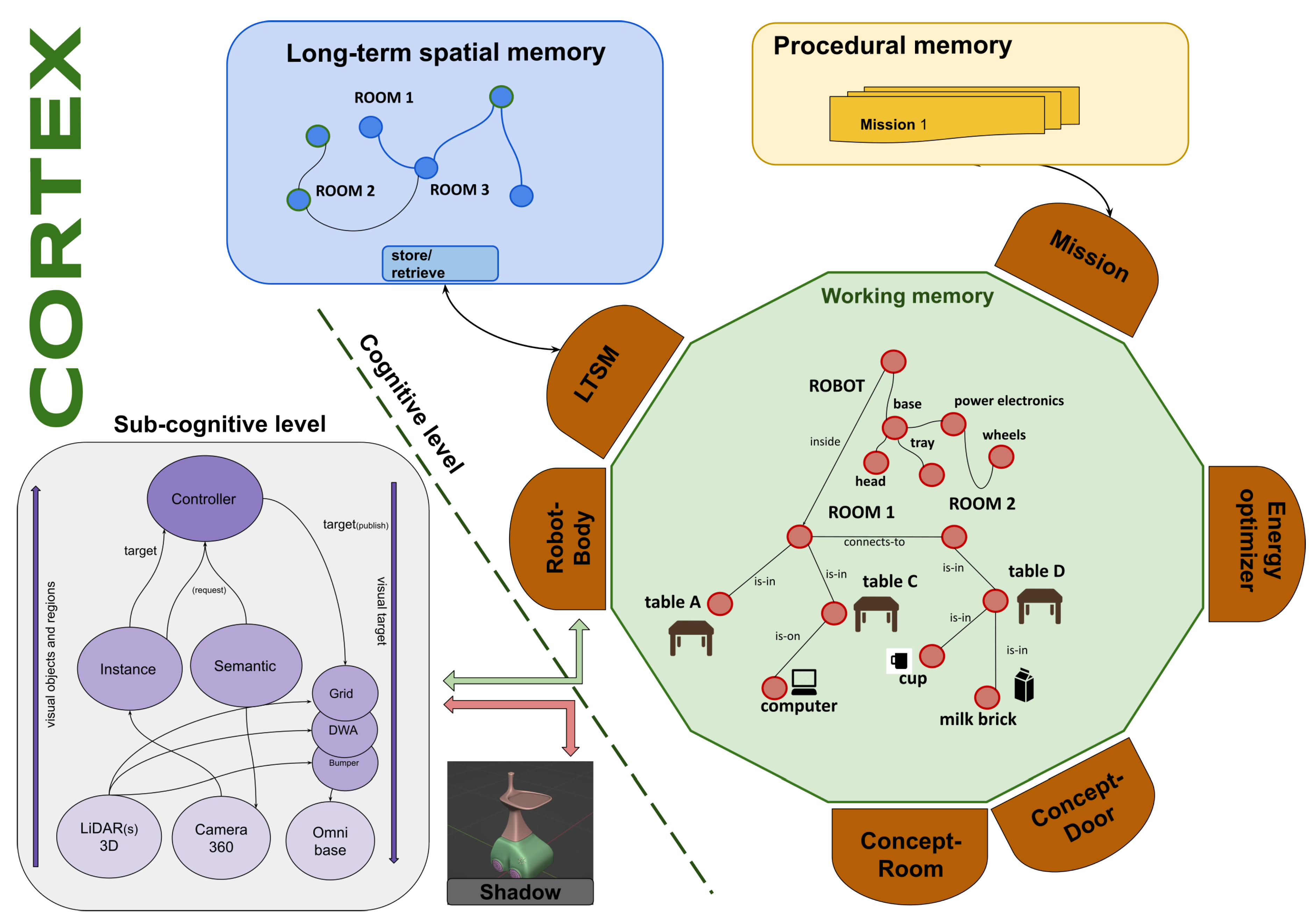
Figure 3.
Graph state transition. The robot starts as the graph’s initial frame (root is a dummy node) and transforms to hang from the new room when it is inserted in the graph. corner_x_measured are nodes that hold the measurements of the corners matched with the corresponding nominal ones on the right.
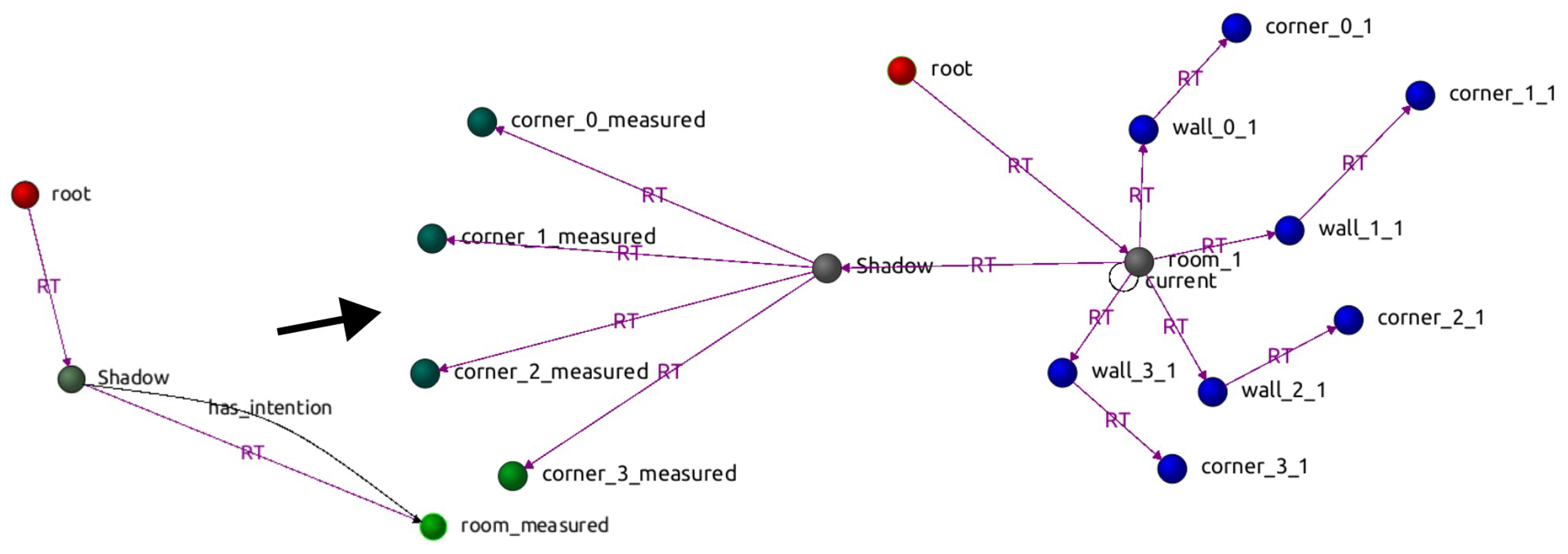
Figure 4.
Flow chart showing the life-cycle of a concept. The two outgoing lines of the first decision box cover the insert new instance and update existing instances situations.
Figure 4.
Flow chart showing the life-cycle of a concept. The two outgoing lines of the first decision box cover the insert new instance and update existing instances situations.
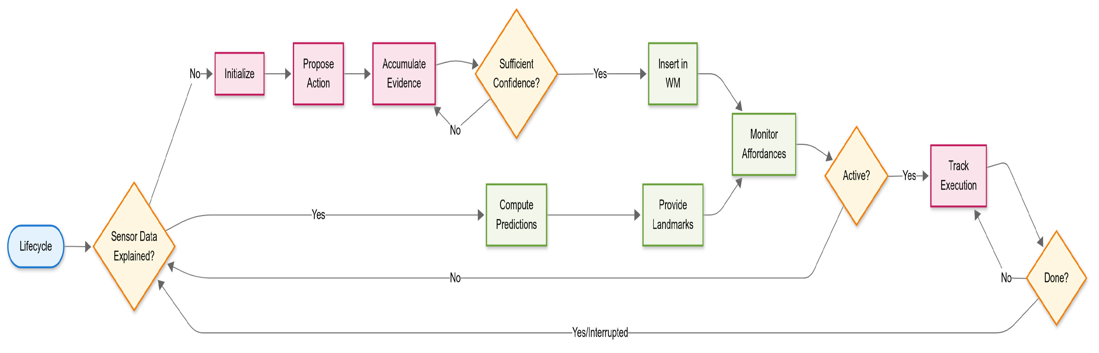
Figure 5.
LTSM rooms representation. The scenario used in the Webots simulator for the experiments is shown in the upper-left image. The down-right area shows a metric reconstruction of the graph on the right. The right image shows the network generated and stored by the LTSM agent after the robot has toured rooms 1 to 4. The red circle marks the loop closure between rooms 4 and 1 as an edge connecting door_3_0_1 and door_1_2_4.
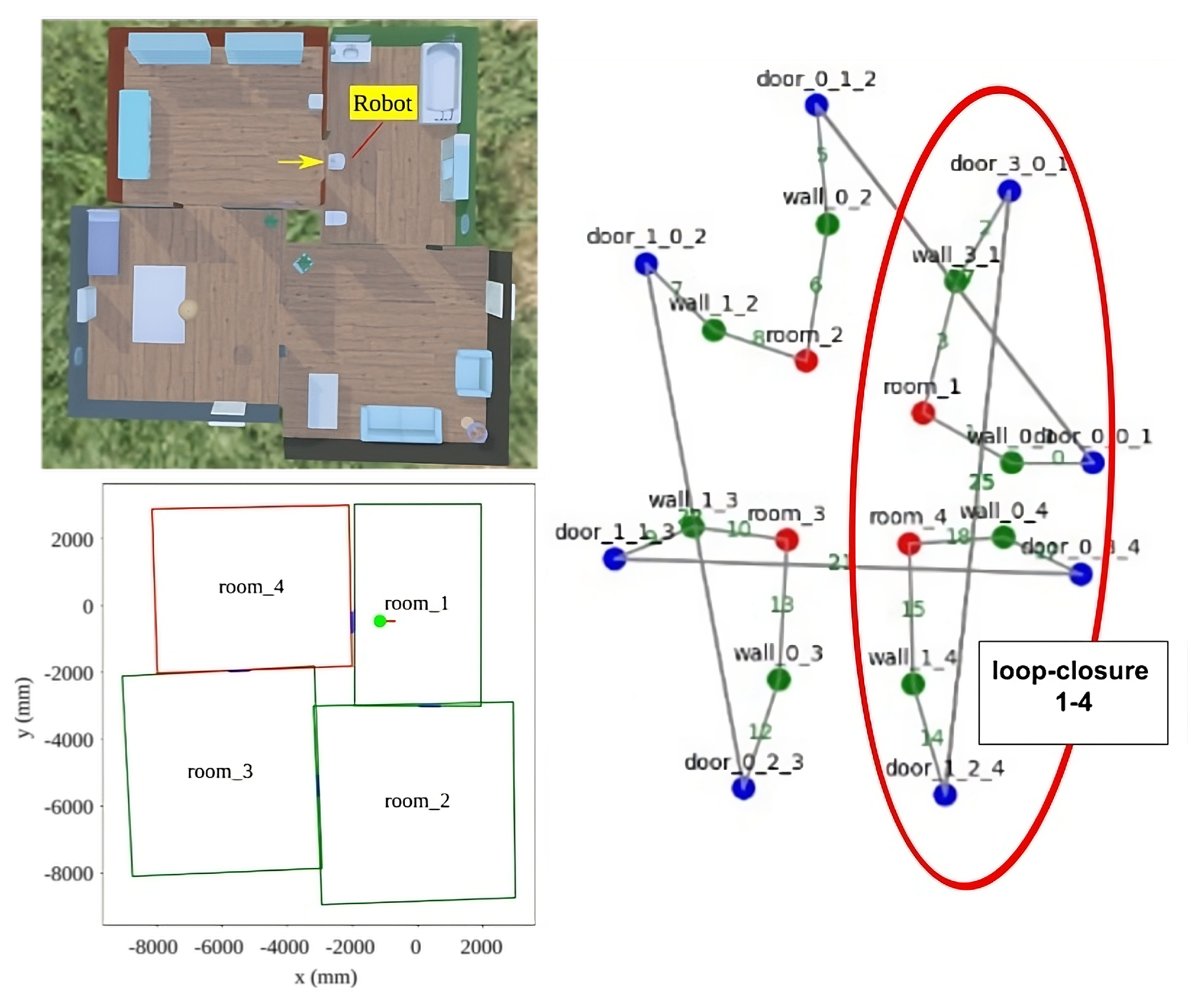
Figure 6.
Schematic view of a robot displacement starting at the black circle and advancing through the upper left quadrant. Small grey squares with an f are factors, i.e., positive functions measuring a difference between two variables, that link the robot to the objects’ parts, corners and anchor points. Plain grey squares are fixed constraints between elements. The sum of all differences accounts for the system’s free energy and is absorbed by the set of past robot poses depicted as red triangles. As more objects are modelled in the WM, more factors are created, and the localisation of the robot will be more robust.
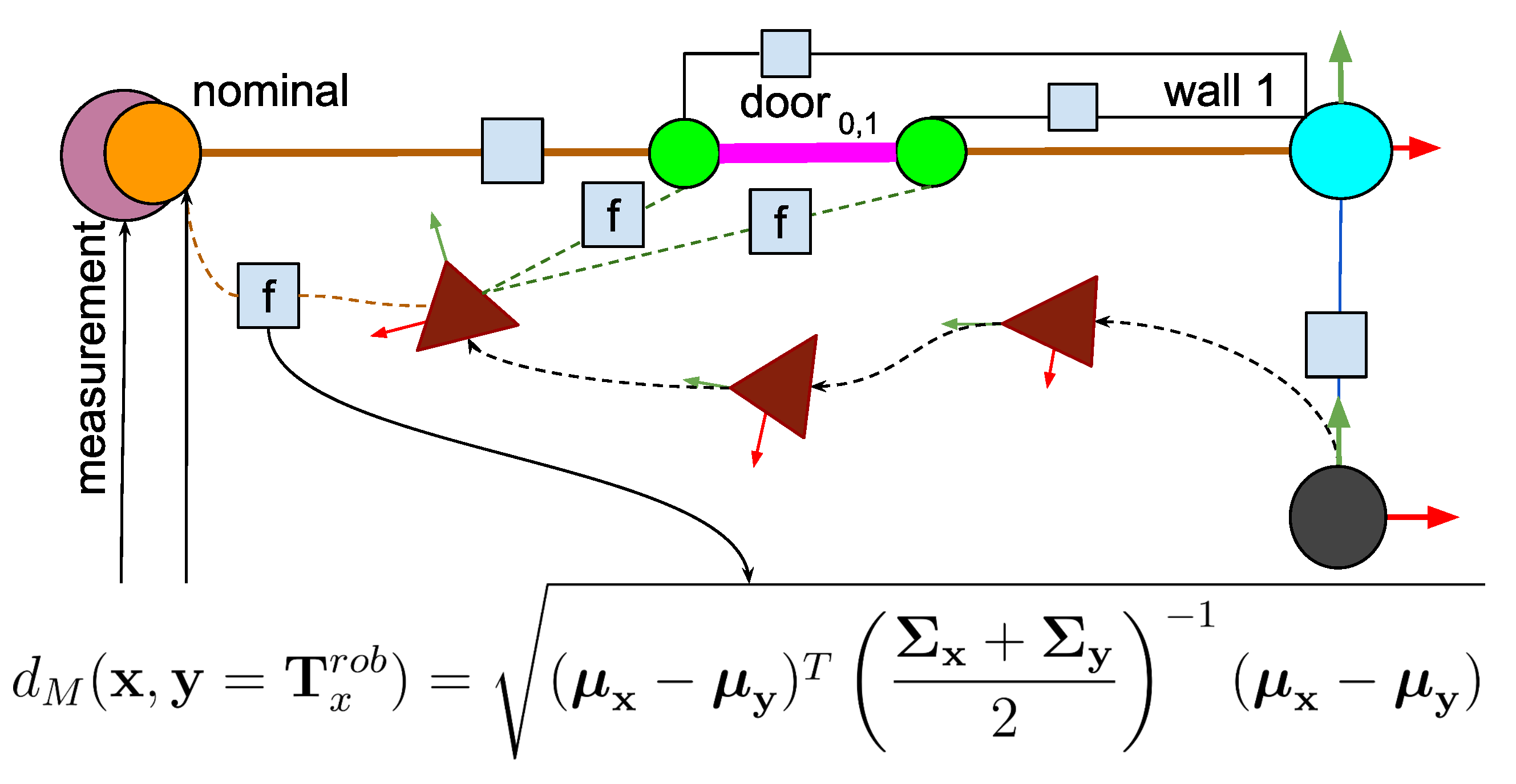
Figure 8.
Real test scenario with their respective layouts.
Disclaimer/Publisher’s Note: The statements, opinions and data contained in all publications are solely those of the individual author(s) and contributor(s) and not of MDPI and/or the editor(s). MDPI and/or the editor(s) disclaim responsibility for any injury to people or property resulting from any ideas, methods, instructions or products referred to in the content. |
© 2025 by the authors. Licensee MDPI, Basel, Switzerland. This article is an open access article distributed under the terms and conditions of the Creative Commons Attribution (CC BY) license (http://creativecommons.org/licenses/by/4.0/).
Copyright: This open access article is published under a Creative Commons CC BY 4.0 license, which permit the free download, distribution, and reuse, provided that the author and preprint are cited in any reuse.


