Submitted:
04 September 2025
Posted:
10 September 2025
You are already at the latest version
Abstract
Diffractive sail components may be used in part or whole for in-space propulsion and attitude control. A sun-facing hybrid diffractive solar sail having reflective front facets and transmissive side facets is described. This hybrid design seeks to minimize undesirable scattering from the side facets. Predictions of radiation pressure are compared for analytical geometrical optics and numerical finite difference time domain approaches. Our calculations across a spectral irradiance band from 0.5 to 3μm suggest the transverse force in a sun facing configuration reaches 48% when the refractive index of the sail material is 1.5. Diffraction measurements at a representative optical wavelength of 633nm supports our predictions.
Keywords:
radiation pressure force
; diffraction
; solar sail
; momentum transfer efficiency
; hybrid reflection/transmission
; geometric optics
; fabrication
; numerical simulation
1. Introduction
In the 1920’s, Tsander and Tsiolkvosy proposed using radiation pressure from the stars to propel objects in space[1,2]. Over the past half century numerous organizations (e.g., NASA, JAXA, ESA, and The Planetary Society) have developed mission concepts and in-space demonstrations [3,4,5,6]. In recent years, studies on both transmissive and reflective sails have been conducted analyzing the sail’s flight dynamics and survivability on low-earth-orbit trajectories as well as diffractive sails in displaced orbits for asteroid deflection [7,8]. Perhaps the most promising class of such missions achieves inward (outward) spiral trajectories by decreasing (increasing) the orbital velocity, i.e., by producing a force perpendicular to the sun line. This force is attributed to the change of optical momentum owing to light scattering. A reflective solar sail tilted by roughly from the sun line was originally proposed for this mission type. At that angle an ideal reflective sail converts of the available optical momentum into the component of force perpendicular to the sun line. In practice the efficiency will be smaller than this value owing to a combination of absorption in the metallic layer, wrinkling and bowing, diffuse scattering, and re-radiated heat [9]. Additionally, the cant angle of a reflective sail may introduce a misalignment between science instruments and the sail axis, posing engineering challenges such as momentum management and thermal control. More technically difficult solar sailing missions seek to achieve large accelerations along the sun line, placing for example a solar sail at the gravitational lensing point of the sun [10,11].
The law of conservation of linear momentum suggests that the transverse momentum transfer efficiency may reach if two ideal conditions are satisfied: the sail is sun-facing (i.e., not tilted), and all available sunlight scatters in a single direction. There is no known optical phenomenon that satisfies these conditions for wavelengths spanning the entire solar spectrum. Diffractive sails were proposed as a means to address the sun-facing condition [12] and to explore whether large momentum transfer efficiencies can be reached. Radiation pressure has been directly measured on commercially available diffraction gratings [13], as well as geometric phase gratings [14]. Measurements have also been recently reported on a microscopic metasurface [15]. Orbital trajectories of diffractive sails in the sun-facing condition have also been explored [16,17,18].
In the ideal case long period gratings were found to be more favorable for achieving large values of the net transverse momentum transfer efficiency (MTE) compared to short period gratings [19] . In practice light does not exhibit ideal scattering. For example surface relief gratings impose obstructions from the facets, scattering light in undesirable directions. Here, we propose a potential solution to this problem by designing a partially reflective hybrid grating that reflects light from the front facets and transmits light through the side facets, as depicted in Figure 1. If a significant fraction of sunlight can be cast at a large average angle then a hybrid diffractive sail may have advantages that differ from those of a flat canted reflective sail.
This report is organized into the following sections. The principle of momentum transfer is used to describe radiation pressure in Section 2. Ray tracing using geometric optics principles is used to estimate radiation pressure on a right prism in Section 3. The reflected and refracted ray directions may be used to describe the optical field near a grating comprised of a periodic array of such prisms. Wavelength dispersion and polarization are ignored in Section 3. Far from the grating the optical field is described with wave theory, which is reviewed in Section 4. In this section the MTE is wavelength dependent owing to diffraction, and thus the net MTE is found by integration over the spectral irradiance distribution of the light source. Both Section 2 and Section 3 provide tractable equations that aid in the design of diffractive light sail. These two approaches do not account for physical phenomena such as polarization-dependent Fresnel reflection and transmission coefficients, and internal reflections within the structure. More accurate modeling requires the use of a numerical Maxwell solver. Using such solvers we calculate the MTE using two methods: The Maxwell stress tensor in Section 6, and in Section 7 a rigorous modal analysis that is closely aligned with Section 4. Results from the latter two approaches are discussed in Section 8. Preliminary experimental results are presented in Section 9 for a long period grating () [20]. The concluding section includes a comparison between the MTE values obtained using both the geometric optics approximation and the Maxwell solver solutions. For example, at a refractive index of , a prism angle of , and a grating period of the geometric optics approximation greatly overestimates the Maxwell solver value . We attribute this discrepancy to the fact that the wavelength of light are on the same order of magnitude as the grating period, resulting in strong diffraction effects not accounted for by the geometric model. On the other hand, when the grating period is much greater than the illuminating wavelengths, geometric optics is expected to provide a better agreement. In fact, the experimentally measured MTE values using a grating period of is in good agreement with the geometric optics value: v.s. , respectively.
2. Radiation Pressure Review
The force owing to radiation pressure may be understood by combining Newton’s second law, which asserts that the force on a body is equal to the change of momentum per unit time, and Newton’s third law, stating that for every action there is an equal and opposite reaction [21]. Let us describe light of wavelength as a collection of rays or photons having momentum where ℏ is the Planck constant and is the magnitude of the wave vector. If incident and elastically scattered wave vectors, and subtend the optical axis with angles and respectively, then the relative change of the momentum provided to the scatter may may be expressed
In the case there is no scattering and Equation (1) provides as expected. Further, if light is back scattered (e.g., light normal incident upon an ideal mirror) such that then , providing a magnitude is the direction of the incident beam. As another example, consider light scattered at right angles to the incident beam such that so that . Projecting onto the incident direction provides a relative momentum change of in that direction. Furthermore, projecting onto the scattering direction provides in that direction. The latter represents the optimal transverse MTE; the ability to attain it is desirable for solar sailing missions where a large radiation pressure component of force perpendicular to the sun line allows a lightsail to spiral toward or away from the sun [9]. If a bundle of rays of combined power all participate identically in the scattering process then the radiation pressure on the scatterer is given by . On the other hand, a correction factor is required if for any reason all the rays do not participate, e.g., when a flat solar sail is not sun-facing, reducing its effective cross-section by where is the sun incidence angle.
3. Geometric Optics Approximation
Our proposed hybrid diffractive sail, illustrated in Figure 1 (A), shows light incident from the left at normal incident to the plane of the sail. The sail is comprised of a series of right triangular prisms of base length and apex angle . A portion of the beam is reflected from the front facet (blue colored rays in the diagram), and the remainder of the beam is transmitted through the side facet and then out the back face. The fraction of reflected and transmitted beam power is given by the respective ratios and , where is the incident beam power. Expressions for the characteristic front and back “window" widths and may be found by defining an effective threshold height delineating which rays are reflected and which are transmitted:
from which we obtain
Note that the powers and lengths must all be positive, and thus . Also note that equal amounts of power are transmitted and reflected when .
Radiation pressure on the hybrid sail has two sources: the reflected beam and the transmitted beam. At normal incidence the weighted radiation pressure force may be expressed where
where use has been made of the following front and back surface angles: Front surface scattering angle where the law of reflection provides ; Back surface scattering angle . The transmitted deviation angle is governed by Snell’s law at the back face:
The internal angle is governed by refraction through the side facet and internal reflection from the front facet:
where . A critical condition may exist at the output face where light undergoes total internal reflection, i.e., if . Solving for the value of n at the critical condition when provides . Calculated values of the back deviation angle are plotted in Figure 2, along with the front deviation angle for comparison.
The net transverse and longitudinal components of the momentum transfer efficiencies are therefore
Values of and are plotted in Figure 3 as a function of the apex angle for different refractive index values. Larger values of refractive index provide larger values of . For example when the values and at .
4. Wave Optics Approach
Whereas the foregoing geometric optics analysis describes the direction of light at the front and back faces of the structure, a diffractive wave analysis is required to describe the distribution of light in the far field. First we make use of the Floquet-Bloch theory for a function having period and wave vector magnitude :
If describes a transmission function and describes an incident planar electric field at , then the propagating transmitted field in the half space for the wavelength may be expressed
where is the transverse component of the incident wave vector, is the angle the incident wave subtends the optical axis, and is the longitudinal component of the propagating field, described below.
The transmission function of the prism grating described above may be approximated by over a range of length and zero valued otherwise, where , and is the refraction angle found from geometrical optics. Setting the dummy variable we write
and hence the total propagating field is given by
Hence the field is a superposition of order components having the phase, where . Since the wavelength can not change, the wave vectors magnitudes must all be equal and thus
The value of must be real for the field to propagate to infinity, and thus m can only assume the values satisfying .
If we equate the component of to a single term: then we obtain the so-called grating equation:
The irradiance of the order plane wave described by Equation (11b) is given by
The intensity is a maximum for the value of m that best satisfies , i.e.,
The same formalism can be applied to the optical field reflected from the front facet by replacing with the front deviation angle , with , and by changing the sign of .
Although a simple closed form expression for does not generally exist, one may expect stronger scattering at angles that satisfy either the law of reflection for reflected light, or Snell’s law for the transmitted light, especially in the geometric optic limit (see Section 5).
For a light source having the spectral irradiance distribution the momentum transfer efficiency of the transmitted light can be estimated from diffraction theory. Integration over frequency where c is the speed of light is adopted instead of integration over wavelength because the former provides equal sampling intervals across the diffraction orders.
where , , , , , and . The extremum mode values are given by and , where INT is the operation that returns the integer value of the argument, rounded toward zero.
For front surface reflections at the deviation angle
where , , , , , and .
A factor of must be in included in Equations (16) and (17) in the event the light source overfills the sail, as occurs in space. In the laboratory, the light source may be a small pencil of light that underfills the sail and thus does not acquire the projection factor. At normal sun incidence Equations (16) and (17) may be expressed
where . Note that these equations do not account for effects such as polarization and internal reflections. Section 6 will address such issues.
5. Wave - Ray Comparison
Let us briefly compare the ray and wave optics predictions for , which allows a solar sail to propel toward or away from the sun via a spiral trajetory. We expect the two approaches to agree in the small wavelength limit, . A more complete description is provided in the next section. In the case of normal sun incidence and refractive index , the transmitted rays are undeviated . Therefore the MTE is solely attributed to front surface reflections. To make use of the above diffractive analysis we simply replace with . For example, the ray optic analysis predicts a peak value of at , resulting from the product of and the sine of the deviation angle ; whence . For comparison a scatter plot of the angular distribution of diffracted modal intensities for a grating of period and wavelengths ranging from is shown in Figure 4. As expected from diffraction theory, the peak modal intensity agrees with . Although this peak appears at , the mean centroid is slightly lower owing to the diffractive cut-off at . The net transverse MTE is , a loss of efficiency compared to the geometric optics value of . The inset in Figure 4 depicts the narrowing of the angular distribution when the period greatly exceeds the wavelengths of the light source (e.g., when ), in which case the two models agree.
We expect the deviation angle of the transmitted rays to be greater than zero when and thus the net transverse MTE is predicted to increase.
6. Maxwell Stress Tensor Numerical Analysis
To account for the effects of polarization-dependent Fresnel reflections and multiple internal reflections within the hybrid structure, a model that satisfies Maxwell’s equations is required. Although this approach does not provide tractable closed forms solutions, numerical open source and commercial software packages are readily available [22,23,24]. Another approach involves a rigorously coupled wave analysis [25]. These packages typically compute radiation pressure from the Maxwell stress tensor (MST) which represents the momentum flux density of the electromagnetic field:
where and are the permittivity and permeability of free space respectively, is the Kronecker delta function, and and are the electric and magnetic field amplitudes respectively for the s and p polarized component of light at the optical frequency , with indexes corresponding to cartesian coordinates and . The components of force in the x and z directions may be found by integrating over a close surface S. For a infinite periodic grating the net momentum flux into a unit cell of length from the two adjacent unit cells must cancel. Thus it suffices to integrate over a front surface in the direction and back surface in the direction over one unit cell of area . The total area of the sail may be expressed where and are the side lengths of a rectangular sail, and and . At a given optical frequency the components of force on a single cell of area may be expressed
These expressions can be calculated by Maxwell solvers such as MEEP. For example, Srivastava [26] showed using MEEP that a low-refractive-index metasurface grating produces a larger transverse radiation pressure force compared to gratings comprised of silicon nitride. For s-polarized light (TE) the electric field is perpendicular to the plane of incidence: , whereas for p-polarized light (TM) the magnetic field is perpendicular to the plane of incidence: . Thus the stress tensors needed for the radiation pressure on the grating may be expressed
It is important to note that MEEP calculates the MST at a given frequency for a unit irradiance, (i.e., not for an arbitrary value consistent with the spectral irradiance of the light source). Thus, for given spectral irradiance distributions the net components of force are found by integration over all frequencies:
For unpolarized light . For example the solar irradiance incident on the Earth may be approximated by the blackbody frequency spectral irradiance distribution:
where [m] is solar radius, [m], [J· s] is the Planck constant, c is the speed of light, and [J/K] is the Boltzmann constant. We let [K] as the effective surface temperature of the sun whereupon integrating over all frequencies provides the so-called solar constant [W/m2]. Thus for a light sail orbiting at the semi-major axis of the Earth, the force on each element of area at normal sun incidence is given by
The components of the MTE are then found by dividing by the characteristic force magnitude :
Note that MEEP is unable to account for the illumination projection factor in the event the illumination source overfills the sail area, in which case must be replaced by .
It is not practical to determine the MST across all frequencies in MEEP, as computational resource demands and computing times becomes unwieldy when . For this reason we limit the integration from an arbitrary minimum frequency somewhat below the diffractive cut-off condition, , to an arbitrary upper value . Unless stated otherwise, a normal sun incidence angle is assumed, as well as a grating period , a minimum frequency , and a maximum frequency corresponding to . This range of frequencies encompasses 75% of the solar frequency spectrum as illustrated in Figure 5 (right).
In the geometric optics model described in Section 3 for the case where the prism refractive index was unity, the peak value of was found at the prism angle (see Figure 3). Larger peak values of were predicted for larger value of n, in which case the value of was marginally larger. Using MEEP to calculate across the frequency range 50-600 THz, and making use of the complex refractive index values of gold and aluminum, we found similar results for a prism index of . The front facet was metallized with thick coating. The calculated variation of vs. is plotted in Figure 5 (left). The spectral reflectance curves plotted in Figure 5 (right) illustrate the general trend for metals, e.g., the s-polarized field (which is tangential to the interface) is more strongly reflected than the p-polarized field (which has a component normal to the interface). The higher reflection values are expected to provide larger values of . The average (unpolarized) value peaks at at .
The polarization-averaged differences between aluminum and gold are negligible and the choice of material depends on other concerns such as mass density, spectral bandwidth, and space weathering. The low reflectance of gold at wavelengths shorter than (above 600 THz) is also a concern. A comparison of the values of for the numerical MST analysis and the geometric optics analysis shows a smaller value in the former case, which we attribute to p-polarized light.
The geometric optics model also predicted that for a given value of , the value of increases with increasing refractive index (see Figure 3). Let us compare this prediction with the MEEP model. The polarization averaged spectral distributions for aluminum are plotted in Figure 6 for three different prism refractive index values, , resulting in the corresponding frequency-integrated values , , , and , , The grating period corresponds to a fundamental frequency THz which corresponds to the diffractive cut-off frequency. Evidence of strong diffractive effects at multiples of is evident in Figure 6.
7. Modal Numerical Analysis
In Section 3 and Section 6 we calculated the momentum transfer efficiency with respective geometric optics and Maxwell stress tensor models. A third method based on modal analysis was described in Section 4. In the later case closed form analytical expressions for the frequency-dependent modal intensities were determined (see Equation (18a)). That model was unable to physically account for the scattering of light in the diffractive frequency cut-off zone (). Maxwell solver software packages such as MEEP overcome this shortcoming, albeit over a limited frequency band.
where the MEEP program determines the normalized front and back modal intensities, and where , and the wave vectors scattered out the front and back . In practice and may different. The factor is the normalized spectral irradiance of the light source. As stated previously for normal sun incident . For cases where the bandwidth of the source is restricted, we opt to normalize not with the full solar constant but instead with the band-limited factor:
The factor preceding accounts for the equal distribution of unpolarized sunlight into the two polarization states. In our case where 50 THz and 600 THz, the normalization constant in the denominator is of the solar constant (see Figure 5).
8. Comparison of Diffractive and Maxwell Stress Tensor Models
Let us compare the transverse momentum transfer efficiency discussed in Section 6 with the diffracted modal analysis presented in Section 7. Values of the calculated spectral MTE for a grating with m, , and are plotted in Figure 7, with Maxwell stress tensor and modal analysis results depicted by solid and dashed lines respectively. The two methods agree well (< 5% difference) across most of the spectrum but begin to diverge at higher frequencies. This deviation may be attributed to the limited number of diffractive modes considered in the modal analysis.
The longitudinal values of do not display the cut-off signature characteristic of at THz. This is attributed to the fact that no modes other than the zero order mode propagates when . We note that both polarization components for and depict transitions at integer multiples of . These are attributed to diffraction cut-off conditions at higher diffraction orders.
9. Hybrid Grating Fabrication and Verification
To help assess the veracity of the above calculations direct-write grayscale lithography (DWL) was used to fabricated a hybrid grating comprised of a low index polymer via a polymer replication process. This technique is suitable for long period structures (compared to visible wavelengths) and may therefore be expected to agree with the high optical frequency results from our MEEP simulations. To provide structural stiffness the polymer grating ( = 1.56) was applied to a 2 mm thick boro-float substrate ( = 1.47). The long slanted facet of the grating was coated with 70 nm of aluminum using physical vapor deposition, leaving the shorter side facet uncoated. An scanning electron microscope (SEM) image of a replicated hybrid grating, depicted in Figure 8, indicates rounded features owing to the fabrication process. To lessen the degree of non-ideal scattering from the rounded regions we elected to produce a grating of period , height , and prism angle . The angular scattering distribution shown in Figure 9 was measured with a purpose-built in-house scatterometer at the HeNe laser wavelength [nm]. As many as diffraction orders are expected on each side of the optical axis.
The scattering data was used to calculate the theoretically expected momentum transfer efficiencies:
where is the scattered HeNe beam power and the irradiance values have been adjusted for bias and gain:
where is the sum of the average value of in the range and one standard deviation, is the sum of the average value of in the range and one standard deviation, is the estimated relative gain factor of the two measurements, and the STEP function sets negative values to zero. The corresponding high optical frequency MEEP values are and . The measured and calculated values of are in good agreement. The discrepancy between the values of may be attributed less back-reflection from the fabricated structure.
10. Conclusions
We examined a hybrid reflection/transmission grating comprised of metallized front facing facets and transmissive side facing facets as shown in Figure 1 for solar sailing missions requiring spiral trajectories toward (or away from) the sun. The hybrid grating is designed to reduce the effects of undesired scattering from the side facets while maintaining a sun-facing orientation. We compared the radiation pressure force efficiency on the grating using geometric optics approximations and numerical finite difference time domain methods. Additionally, a prototype hybrid grating was fabricated to verify the momentum transfer efficiency predicted in the geometric and numerical studies.
Making use of the Maxwell solver MEEP we computed the momentum transfer efficiency of a hybrid grating of period and apex angle , finding the net transverse MTE in a sun facing configuration reaches when the refractive index of the sail material is 1.5. At optical frequencies beyond our upper computational range of 600 THz (i.e., shorter than ) a geometrical optics limit (where diffraction effects become increasingly negligible) is expected whereupon the MTE becomes weakly independent of wavelength (for example, owing to material dispersion). However, the geometrical optics model presented in Section 3 is insufficient for computing this limit as it does not account for Fresnel reflection and transmission coefficients at the interface between vacuum and the substrate. Nevertheless, the geometrical optics value of when (i.e., no dielectric boundary) is in remarkably good agreement with the Maxwell solver value of . What is more, a hybrid grating designed for the geometrical optics range (with period much greater than the wavelength ) was found to have an angular scattering distribution in excellent agreement with our predicted value of 47% vs 48%. Finally, our numerical model found no significant difference between the use of gold and aluminum for the reflective coating. Aluminum may be preferable, however, owing to absorption in gold beyond 600 THz.
Author Contributions
RC drafted the manuscript and made the numerical and analytical calculations. PRS provided guidance and training in the use of [22] and contributed insights into the interpretation of simulation results. QW fabricated the prototype hybrid grating and completed the scatterometer measurements. TS provided supervision and technical advisement on the fabrication of the hybrid grating prototype. GS supervised the research, provided conceptual guidance, and edited the manuscript.
Funding
This research was funded with a NASA NIAC Phase III award with RIT receiving sub-award number 80MSFC22F0165/JHU APL 177864.
Data Availability Statement
Data provides upon request, subject to institutional approvals.
Acknowledgments
We are grateful to Les Johnson and Andy Heaton (NASA Marshall Space Flight Center, Huntsville, AL) for discussions related to solar sail design, and Amber Dubill, Christine Zgrabik, Joseph Miragliotta, and David Shrekenhamer (Johns Hopkins Applied Physics Lab, Laurel, MD) for discussions related to diffractive solar sail fabrication and design.
Conflicts of Interest
Authors Qing Wang and Tasso Sales were employed by the company Viavi Solutions Inc. The remaining authors declare that the research was conducted in the absence of any commercial or financial relationships that could be construed as a potential conflict of interest.
Abbreviations
The following abbreviations are used in this manuscript:
| DE | Diffraction Model with Maxwell Solver |
| DWL | Direct-Write Grayscale Lithography |
| EM | Electro-Magnetic |
| ESA | European Space Agency |
| FDTD | Finite Difference Time Domain |
| JAXA | Japan Aerospace Exploration Agency |
| MDPI | Multidisciplinary Digital Publishing Institute |
| MEEP | MIT Electromagnetic Equation Propagation |
| MST | Maxwell’s Stress Tensor |
| MTE | Momentum Transfer Efficiency |
| NASA | National Aeronautics and Space Administration |
| TE | Transverse Electric |
| TM | Transverse Magnetic |
References
- Tsander, K. From a Scientific Heritage. Technical Report TTF-541, NASA Technical Translation, 1967. A translation of Iz Nauchnogo Naslediya.
- Tsiolkovsky, K.E. Extension of Man into Outer Space. In Proceedings of the Proceedings of the Symposium on Jet Propulsion, 1921, Vol. 2.
- Johnson, L.; Swartzlander, G.A.; Artusio-Glimpse, A. An overview of solar sail propulsion within NASA. Adv. Sol. Sail. 2014, pp. 15–23.
- Friedman, L. Starsailing: Solar Sails and Interstellar Travel; Wiley & Sons, 1988.
- Vulpetti, G.; Johnson, L.; Matloff, G.L. Solar Sails: A Novel Approach to Interplanetary Travel; Copernicus, 2010.
- Matloff, G. L.; Vulpetti, G.; Bangs, C.; Haggerty, R.; Johnson, L. The Interstellar Probe (ISP): Pre-Perihelion Trajectories and Application of Holography. Contractor Report NASA/CR-2002-211730, M-1046, NASA, Marshall Space Flight Center, Huntsville, AL, 2002.
- Thompson, S.M.; Pushparaj, N.; Cappelletti, C. Reflective and transmissive solar sails: Dynamics, flight regimes and applications. Acta Astronautica 2024, 220, 478–494. [Google Scholar] [CrossRef]
- Chu, Y.; Baoyin, H.; Gong, S. Dynamics and control of sun-facing diffractive solar sails in displaced orbit for asteroid deflection. Aerospace Science and Technology 2024, 145, 108877. [Google Scholar] [CrossRef]
- McInnes, C.R. Solar Sailing: Technology, Dynamics and Mission Applications; Springer, 2004.
- Turyshev, S.; Helvajian, H.; Friedman, L.D.; Heinsheimer, T.; Garber, D.; Davoyan, A.; Toth, V.T. Exploring the Outer Solar System with Solar Sailing Smallsats on Fast-Transit Trajectories, In-Flight Autonomous Assembly of Advanced Science Payloads. Bulletin of the AAS 2021, 53. [Google Scholar] [CrossRef]
- Davoyan, A.R.; Munday, J.N.; Tabiryan, N.; Swartzlander, G.A.; Johnson, L. Photonic materials for interstellar solar sailing. Optica 2021, 8, 722–734. [Google Scholar] [CrossRef]
- Swartzlander, G.A. Radiation pressure on a diffractive sailcraft. J. Opt. Soc. Am. B 2017, 34, C25–C30. [Google Scholar] [CrossRef]
- Chu, Y.J.L.; Jansson, E.M.; Swartzlander, G.A. Measurements of Radiation Pressure Owing to the Grating Momentum. Phys. Rev. Lett. 2018, 121, 063903. [Google Scholar] [CrossRef] [PubMed]
- Chu, Y.J.L.; Tabiryan, N.V.; Swartzlander, G.A. Experimental Verification of a Bigrating Beam Rider. Phys. Rev. Lett. 2019, 123, 244302. [Google Scholar] [CrossRef] [PubMed]
- Michaeli, L.; Gao, R.; Kelzenberg, M.D.; Hail, C.U.; Merkt, A.; Sader, J.E.; Atwater, H.A. Direct radiation pressure measurements for lightsail membranes. Nature Photonics 2025, 19, 369–377. [Google Scholar] [CrossRef]
- Dubill, A.L.; Swartzlander, G.A. Circumnavigating the sun with diffractive solar sails. Acta Astronautica 2021, 187, 190–195. [Google Scholar] [CrossRef]
- Mengali, G.; Quarta, A.A. Optimal Trajectories of Diffractive Sail to Highly Inclined Heliocentric Orbits. Applied Sciences 2024, 14. [Google Scholar] [CrossRef]
- Quarta, A.A. Heliocentric Orbital Repositioning of a Sun-Facing Diffractive Sail with Controlled Binary Metamaterial Arrayed Grating. Applied Sciences 2025, 15. [Google Scholar] [CrossRef]
- Swartzlander, G.A. Theory of radiation pressure on a diffractive solar sail. Journal of the Optical Society of America B 2022, 39, 2556–2563. [Google Scholar] [CrossRef]
- Wang, Q.X. Fabrication of Diffraction Grating Prototype Solar Sails for in-Space Propulsion. Master’s thesis, Rochester Institute of Technology, United States – New York, 2023. Order No. 30810855, ProQuest, accessed August 5, 2025.
- Newton, I. The Principia: Mathematical Principles of Natural Philosophy; University of California Press, 1999. Originally published in 1687.
- Oskooi, A.F.; Roundy, D.; Ibanescu, M.; Bermel, P.; Joannopoulos, J.D.; Johnson, S.G. MEEP: A flexible free-software package for electromagnetic simulations by the FDTD method. Computer Physics Communications 2010, 181, 687–702. [Google Scholar] [CrossRef]
- Lumerical Solutions Inc.. FDTD Solutions, A Commercial Professional Software. Lumerical Solutions Inc., Vancouver, Canada, n.d. http://www.lumerical.com.
- COMSOL AB, Stockholm, Sweden. COMSOL Multiphysics® v6.1, 2022. www.comsol.com.
- Gao, B.; Gersen, H.; Hanna, S. On the suitability of rigorous coupled-wave analysis for fast optical force simulations. Journal of Optics 2024, 26, 125104. [Google Scholar] [CrossRef]
- Srivastava, P.R.; Crum, R.M.; Swartzlander, G.A. Broadband Diffractive Solar Sail, 2023, [arXiv:physics.optics/2306.14093].
- Querry, M.; Polyanskiy, M. RefractiveIndex.INFO - Refractive index database. https://refractiveindex.info, 2008–2025. Accessed: 2025-07-25.
Figure 1.
(A) Near-field geometric optics diagram of a hybrid gratings of height h, period , refractive index n (gray), reflective surface (black), and apex angle depicting reflected (blue lines) and transmitted (red lines) rays. Normal incidence upon the grating plane is assumed. The angles and are the respective front and back surface ray deviation angles. (B) Diffraction grating of period with incident and -order reflected and transmitted wave vectors, , , and making angles , , and respectively. The z and x axes are normal and tangential to the plane of the grating. Diffraction is attributed to the addition of integer multiples of the grating momentum where .

Figure 2.
Back deviation angle as a function of prism apex angle for different values of the prism refractive index n. The front deviation angle is shown for comparison. For a critical condition may exist at some values of where is undefined. When rays exit the back surface undeviated.
Figure 2.
Back deviation angle as a function of prism apex angle for different values of the prism refractive index n. The front deviation angle is shown for comparison. For a critical condition may exist at some values of where is undefined. When rays exit the back surface undeviated.
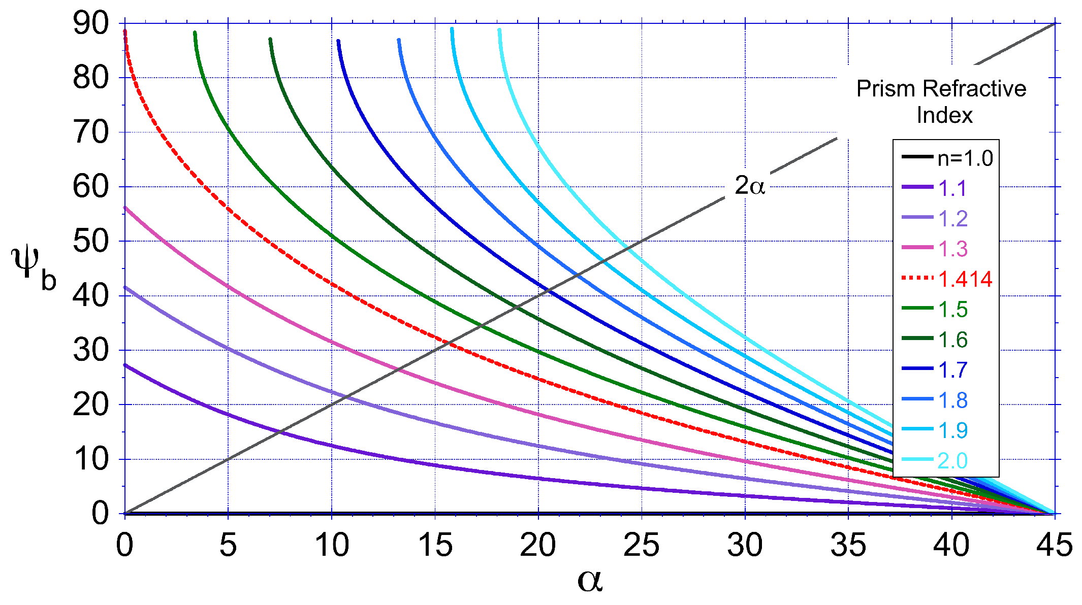
Figure 3.
Geometric optics estimates of the net transverse (top) and longitudinal (bottom) momentum transfer efficiencies, and respectively, for different values of the prism apex angle and refractive index n. Values not shown when total internal reflection occurs at the output face.
Figure 3.
Geometric optics estimates of the net transverse (top) and longitudinal (bottom) momentum transfer efficiencies, and respectively, for different values of the prism apex angle and refractive index n. Values not shown when total internal reflection occurs at the output face.
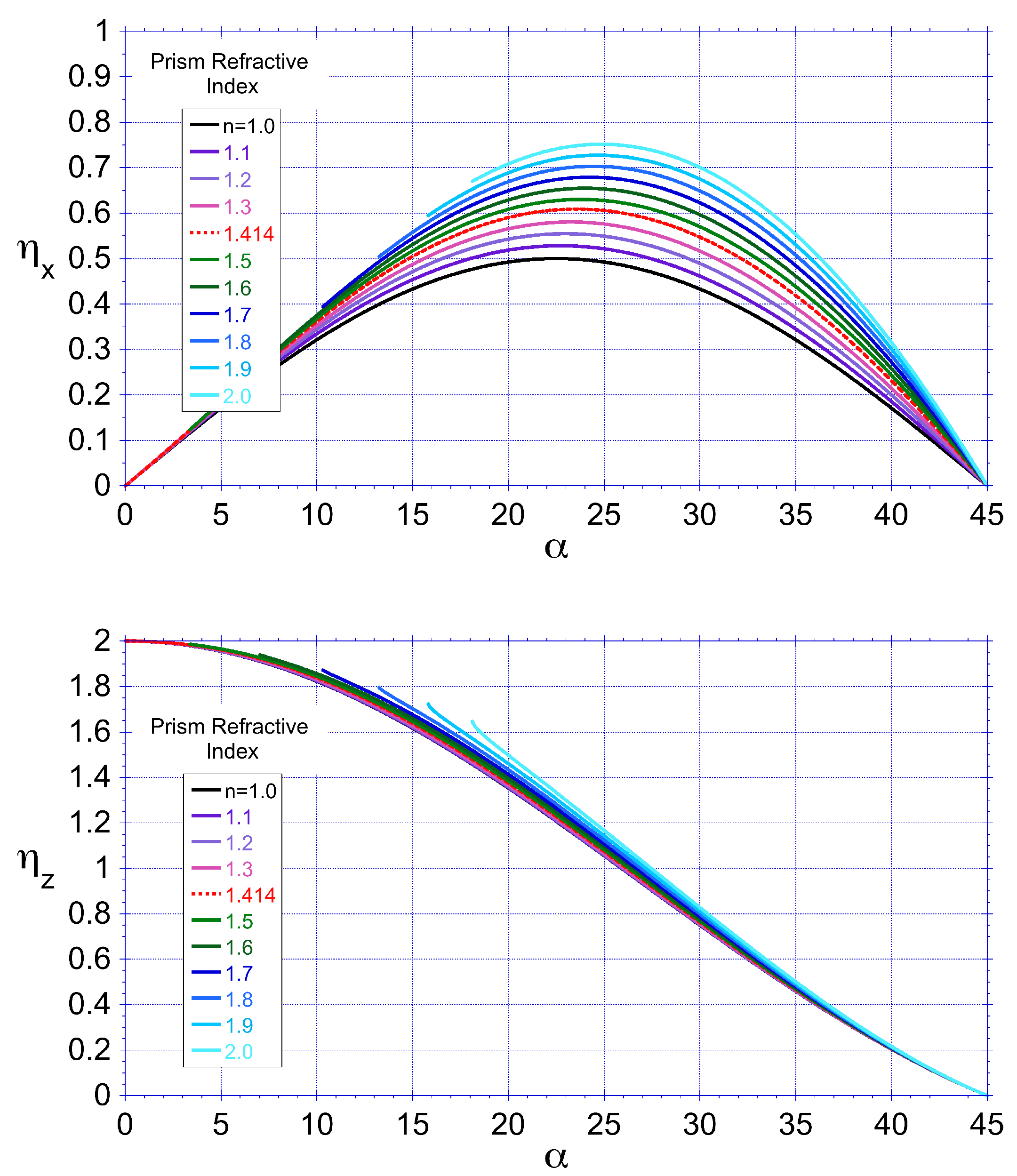
Figure 4.
Scatter plot of the angular spectrum of diffracted modes across a band of wavelengths , assuming reflection from the front facet of a prism of apex angle , period , window width and a deviation angle of . Inset depicts quasi-geometric regime for the same conditions, except .
Figure 4.
Scatter plot of the angular spectrum of diffracted modes across a band of wavelengths , assuming reflection from the front facet of a prism of apex angle , period , window width and a deviation angle of . Inset depicts quasi-geometric regime for the same conditions, except .
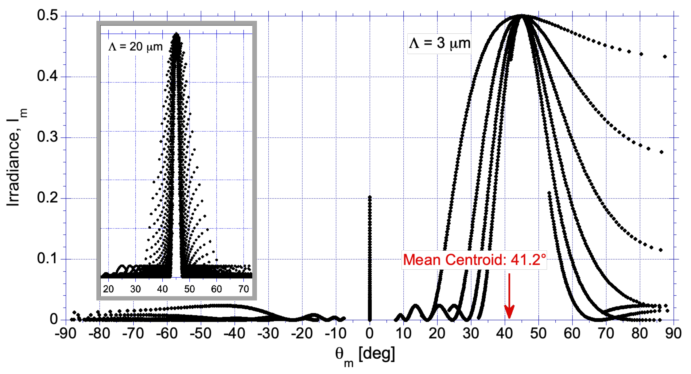
Figure 5.
Left: Polarization dependent net transverse radiation pressure force efficiency for a hybrid grating of m] and varying prism angle . Dark gray (Orange) curves represent a hybrid grating coated with aluminum (gold). Values are frequency averaged across the range 100 THz to 600 THz. Right: Vacuum spectral reflectance calculated from tabulated values of the complex refractive index for aluminum and gold, assuming an incidence angle of ([27]). Solar blackbody irradiance spectrum also shown in units of [W m−2 Hz−1] for [K].
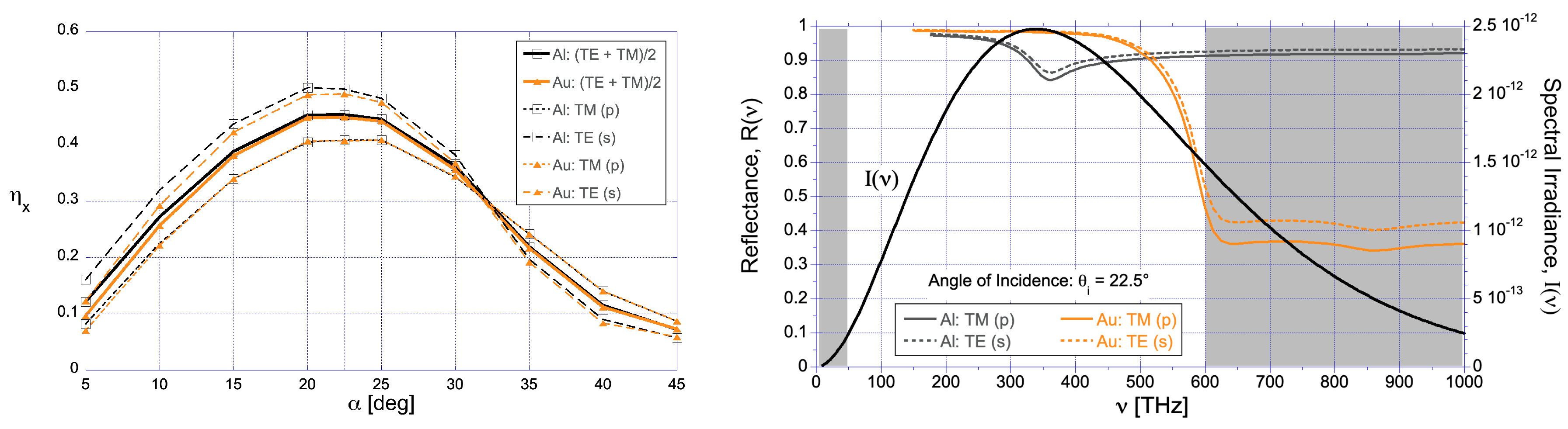
Figure 6.
Spectral momentum transfer efficiency values (Equation (Section 6) ) for three values of refractive index, n, assuming a grating period and an aluminum coating. (top), (bottom).
Figure 6.
Spectral momentum transfer efficiency values (Equation (Section 6) ) for three values of refractive index, n, assuming a grating period and an aluminum coating. (top), (bottom).
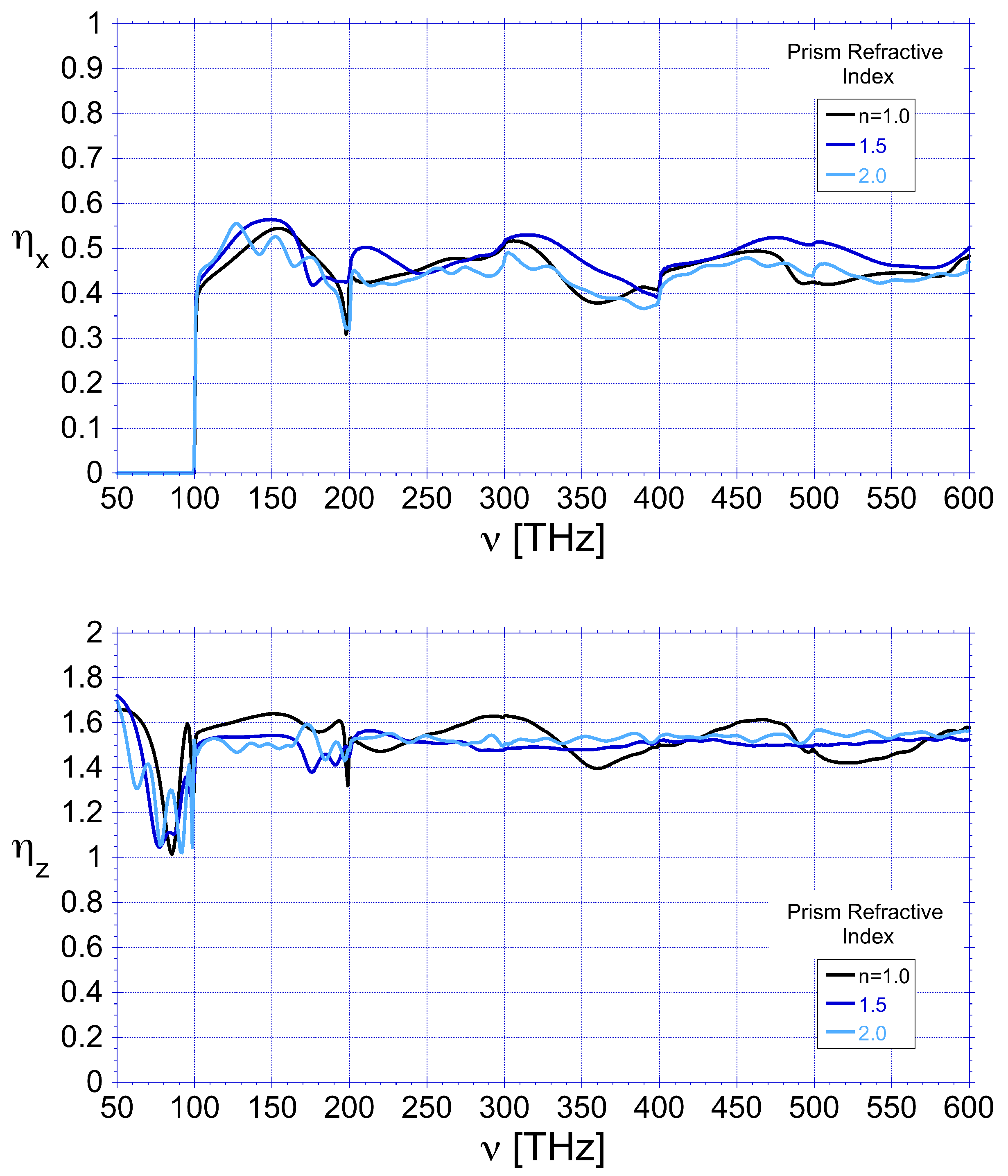
Figure 7.
Polarization dependent spectral radiation momentum transfer efficiencies for a hybrid grating of period and substrate refractive index . Solid line: Maxwell stress tensor method. Dashed line: Modal numerical analysis. Additional diffraction orders are added at integer multiples of the first order cut-off frequency, THz.
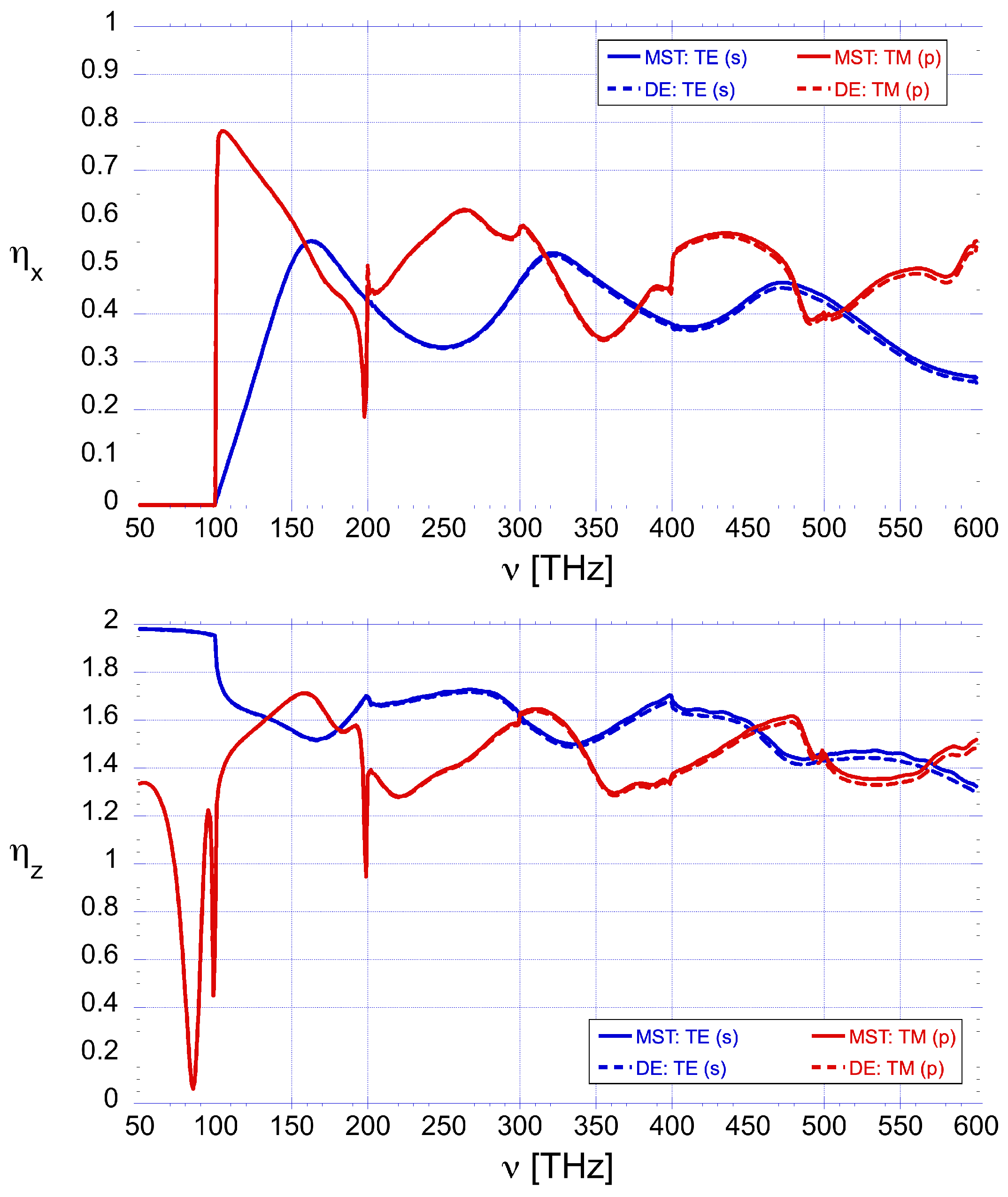
Figure 8.
SEM image of the profile of the fabricated hybrid grating. Undesirable fabrication features are shown in boxed regions. (1) Rounding of the troughs; (2) rounding of the side facets; and (3) rounding of the top vertex of the prisms. These features lead to discrepancies in the designed and fabricated grating period and influence the transverse momentum transfer efficiency.
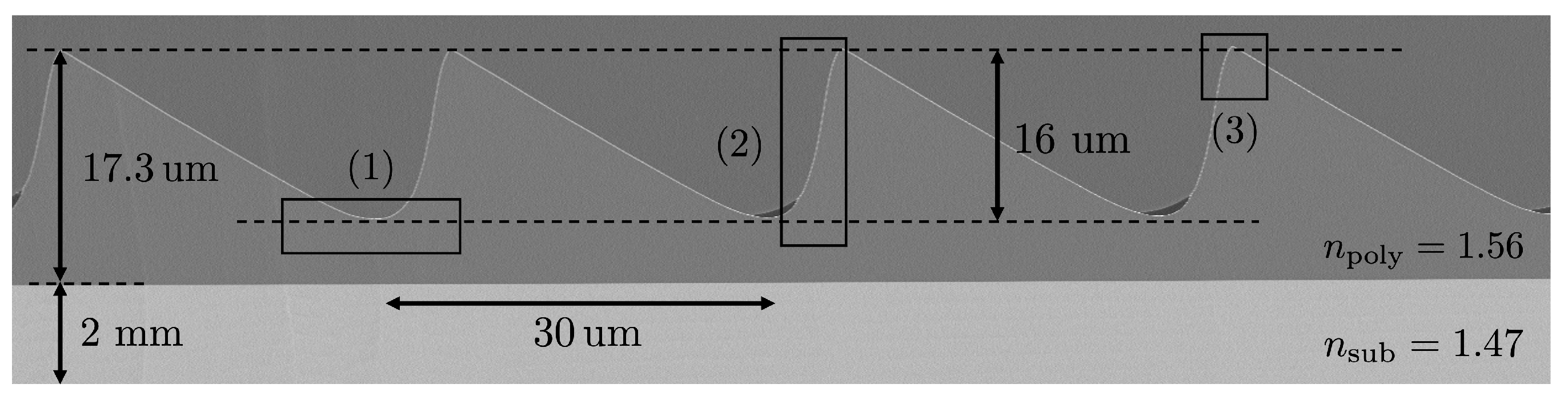
Figure 9.
Reflected (top) and transmitted (bottom) scattering angles for a hybrid grating of m] and .
Figure 9.
Reflected (top) and transmitted (bottom) scattering angles for a hybrid grating of m] and .

Disclaimer/Publisher’s Note: The statements, opinions and data contained in all publications are solely those of the individual author(s) and contributor(s) and not of MDPI and/or the editor(s). MDPI and/or the editor(s) disclaim responsibility for any injury to people or property resulting from any ideas, methods, instructions or products referred to in the content. |
© 2025 by the authors. Licensee MDPI, Basel, Switzerland. This article is an open access article distributed under the terms and conditions of the Creative Commons Attribution (CC BY) license (http://creativecommons.org/licenses/by/4.0/).
Copyright: This open access article is published under a Creative Commons CC BY 4.0 license, which permit the free download, distribution, and reuse, provided that the author and preprint are cited in any reuse.


