
Submitted:
28 August 2025
Posted:
29 August 2025
You are already at the latest version
Abstract
The human lower extremity plays a vital role in locomotion, posture, and weight-bearing through coordinated motion at the hip, knee, and ankle joints. These joints facilitate essential functions including flexion, extension, and internal and external rotation. To address mobility impairments through personalized therapy, this study presents the design, dynamic modeling, and control of a four-degree-of-freedom (4-DOF) lower limb exoskeleton robot. The system actuates hip flexion-extension and internal-external rotation, knee flexion-extension, and ankle dorsiflexion-plantarflexion. Anatomically aligned joint axes were incorporated to enhance biomechanical compatibility and reduce user discomfort. A detailed CAD model ensures ergonomic fit, modular adjustability, and integration of actuators and sensors. The dynamic model, derived using Lagrangian mechanics, incorporates subject-specific anthropometric parameters to accurately reflect human biomechanics. A conventional sliding mode controller (SMC) was implemented to ensure robust trajectory tracking under model uncertainties. To overcome limitations of conventional SMC, an adaptive sliding mode controller with boundary layer-based chattering suppression was developed. Simulations in MATLAB/Simulink demonstrate that the adaptive controller achieves smoother torque profiles, minimizes high-frequency oscillations, and improves tracking accuracy. This work establishes a comprehensive framework for anatomically congruent exoskeleton design and robust control, supporting future integration of physiological intent detection and clinical validation for neurorehabilitation applications.
Keywords:
neurorehabilitation
; adaptive sliding mode control (ASMC)
; biomechanical design
; anatomical joint alignment
1. Introduction
Lower extremity exoskeletons have gained increasing prominence in neurorehabilitation due to their ability to deliver high-intensity, task-specific, and repetitive training that supports motor recovery following stroke, spinal cord injury, and other neurological disorders [1,2]. These systems provide consistent and quantifiable assistance that complements therapist-led interventions and has demonstrated significant benefits in restoring gait, improving balance, and enhancing muscle coordination [2].
Despite their promise, existing exoskeleton technologies exhibit critical limitations in both mechanical design and control. Many devices offer limited degrees of freedom (DOFs), often focusing on isolated joint actuation while neglecting proper anatomical alignment. Others attempt to support multi-DOF motion but compromise adaptability and comfort through rigid structures or non-adjustable linkages [3,4]. These trade-offs frequently result in unnatural joint kinematics, elevated interaction torques, and user discomfort, factors that can diminish therapeutic effectiveness and reduce patient adherence [5]. Achieving biomechanical congruency, where robotic joint axes are aligned with anatomical counterparts, is essential to minimize misalignment strain and enable safe, natural assistance.
To address these challenges, this study presents the development of a 4-DOF human lower extremity exoskeleton specifically designed for rehabilitation applications. The system actuates four essential lower-limb motions: hip flexion/extension, hip internal/external rotation, knee flexion/extension, and ankle dorsiflexion/plantarflexion. Each joint is mechanically aligned with its anatomical axis to ensure kinematic compatibility. The exoskeleton features a modular and anthropometrically adaptable design, including adjustable pantograph linkages to accommodate different limb lengths and a symmetric four-bar mechanism that maintains precise alignment during transverse-plane hip rotations. This architecture promotes user comfort, mechanical safety, and movement efficacy across diverse patient populations.
Beyond its mechanical innovations, the exoskeleton integrates a robust control framework optimized for dynamic human–robot interaction. Conventional strategies, such as fixed-gain PID and Computed torque control, often struggle with nonlinear system dynamics, sensor noise, and inter-user variability. Although adaptive and learning-based controllers improve robustness, they frequently impose computational demands that hinder real-time clinical deployment [6,7]. Sliding Mode Control (SMC) has emerged as a promising alternative due to its resilience against modeling uncertainties and external disturbances [8]. However, classical SMC suffers from high-frequency control signal oscillations, known as chattering, which can lead to actuator wear and user discomfort.
To overcome this limitation, an Optimized Sliding Mode Controller (OSMC) is proposed, incorporating a boundary-layer-based chattering suppression scheme. This approach preserves the robustness of traditional SMC while replacing the discontinuous switching function with a smooth saturation function, effectively eliminating high-frequency oscillations. Hasan and Dhingra [9] recently demonstrated the effectiveness of this controller on a 7-DOF exoskeleton, reporting substantial reductions in torque ripple and energy consumption. The proposed controller is designed for real-time execution, producing low-noise, stable torque outputs suitable for use in sensitive rehabilitation settings. Its computational efficiency supports deployment on embedded systems with limited processing capacity, resulting in an energy-efficient and responsive platform.
An additional innovation of this system is its suitability for bedside and early-stage rehabilitation. Unlike many devices restricted to treadmill or overground walking, the exoskeleton includes a vertically supported, mobile frame that can be aligned with a patient in a bed or chair. This enables joint mobilization exercises without requiring full body-weight support, which is critical for patients in the acute recovery phase who are not yet ambulatory. The system supports both passive and active-assist therapy modes, extending its application from intensive care units to home-based rehabilitation environments. Quick-release joints and simplified alignment mechanisms enhance ease of use, allowing setup and operation without specialized clinical personnel.
In summary, the proposed exoskeleton combines anatomically aligned biomechanics with a chattering-free, computationally efficient control strategy to deliver a safe, modular, and adaptive platform for lower limb rehabilitation. It addresses key limitations in current systems and lays the groundwork for future integration of EMG-driven intention detection and clinical validation.
This paper is organized as follows. Section 1 introduces the motivation and goals. Section 2 synthesizes prior work on mechanical design, anatomical compatibility, human–robot interaction, comfort, and clinical applicability. Section 3 presents the biomechanical model and system architecture, covering actuation, sensing, and safety. Section 4 develops the kinematic and dynamic models under anatomically informed constraints. Section 5 designs an advanced sliding-mode controller with chattering suppression and adaptive gain and derives the implementable control law. Section 6 reports MATLAB/Simulink simulations comparing conventional and adaptive SMC for sequential and simultaneous motions using position, tracking error, and torque metrics. Section 7 discusses findings, limitations, and future directions toward intent-aware control and clinical translation. Section 8 concludes by highlighting the contributions and the expected impact of the developed lower-limb exoskeleton for rehabilitation.
2. Prior Research Synthesis
The human lower extremity is a biomechanical system of remarkable complexity, integrating the hip, knee, and ankle joints to support locomotion, postural stability, and weight-bearing. These joints provide coordinated degrees of freedom (DOFs), such as flexion and extension, internal and external rotation, and dorsiflexion and plantarflexion, all of which are fundamental to natural walking. Accurately replicating these DOFs in robotic systems is essential for rehabilitation. Even small misalignments between human joints and exoskeleton axes can result in unnatural trajectories, discomfort, and long-term musculoskeletal strain [1]. Consequently, the design and control of lower limb exoskeletons have been the subject of extensive research, driven by their potential to deliver intensive, repetitive, and personalized therapy for individuals recovering from stroke, spinal cord injury, or other neuromuscular disorders [10,11,12,13,14,15,16,17]. The following section reviews the recent development of human lower extremity exoskeleton robots.
Human lower extremity (HLE) rehabilitation exoskeletons fall into two main categories:
- Treadmill-Based Stationary Systems
- Mobile Gait Training Devices
These systems differ significantly in terms of mechanical design, degrees of freedom (DOF), control strategies, and user mobility.
- Treadmill-Based Stationary Exoskeletons
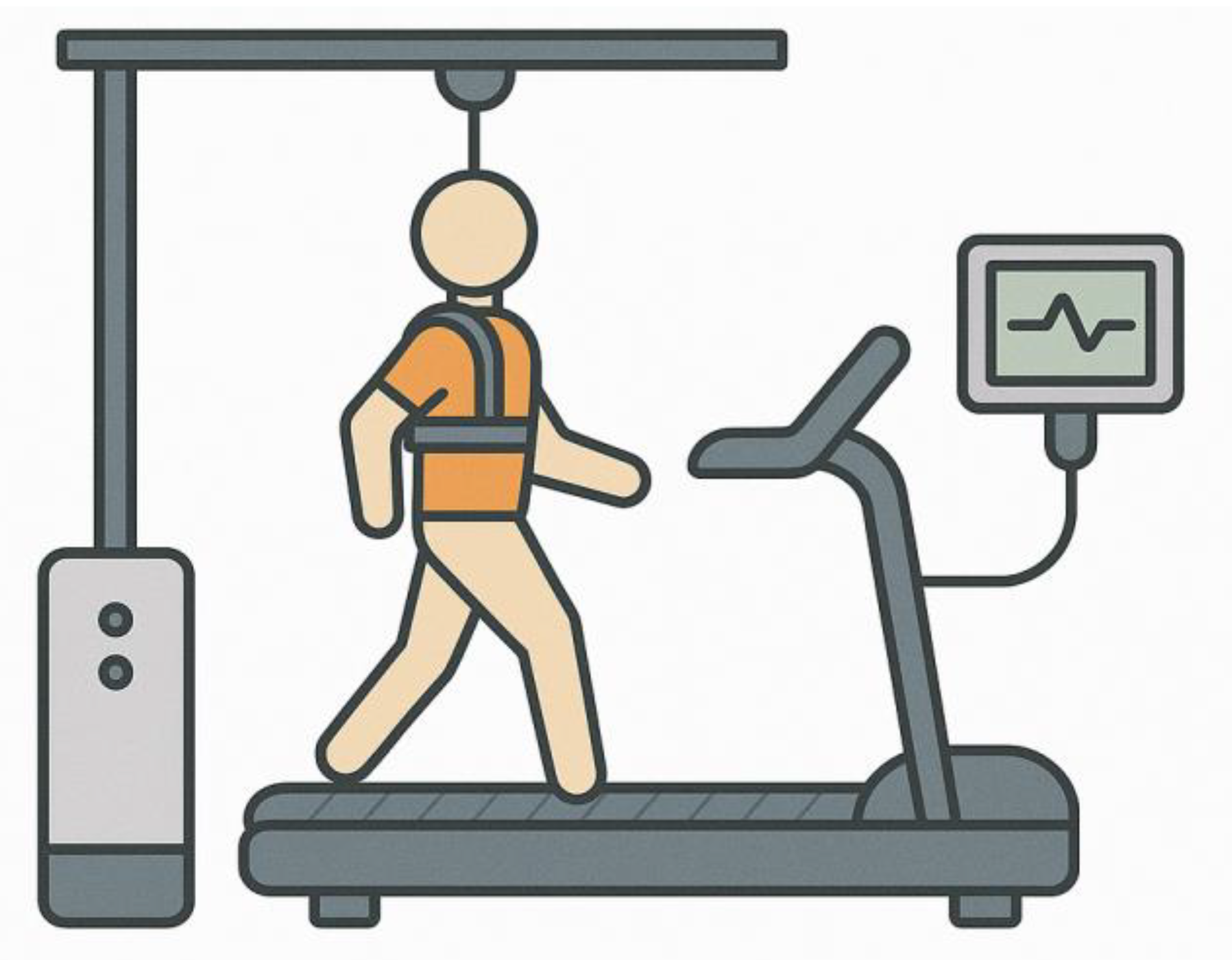
Treadmill-based systems provide a controlled environment for gait training, where the user is usually suspended in a harness and the exoskeleton guides limb movements over a treadmill surface. Some of the prominent research work on treadmill based stationary exoskeleton are given below.
The Lokomat and KineAssist both offer body-weight-supported treadmill training. Lokomat supports hip and knee joints while leaving the ankle passive and uses a force-position control approach [18,19,20]. In contrast, KineAssist enables natural pelvic motion through a vertical displacement mechanism and offers dynamic body-weight support via a mobile robotic base [21,22].
LOPES and ALEX are designed for more naturalistic gait patterns. LOPES incorporates two active DOFs at the pelvis and actuates hip and knee joints using impedance control and series elastic actuators [23,24,25].
Figure 1.
Treadmill-Based Stationary Lower Extremity Rehabilitation Systems.
ALEX, on the other hand, is structured in multiple generations:
- ALEX I offers seven DOFs, with linear actuators for hip and knee and force-field control [26].
- ALEX II improves bilateral actuation and introduces gravity compensation using feedforward-feedback control.
These systems rely heavily on predefined trajectories, stationary support platforms, and structured environments, making them ideal for early-stage, high-intensity therapy.
- Mobile Gait Rehabilitation Exoskeletons
Mobile exoskeletons enable overground walking and allow users to practice in real-world environments. These systems vary in complexity, actuation, and intended use cases. Some prominent research works are given below.
Figure 2.
Lower Extremity Exoskeleton for Overground Gait Training.
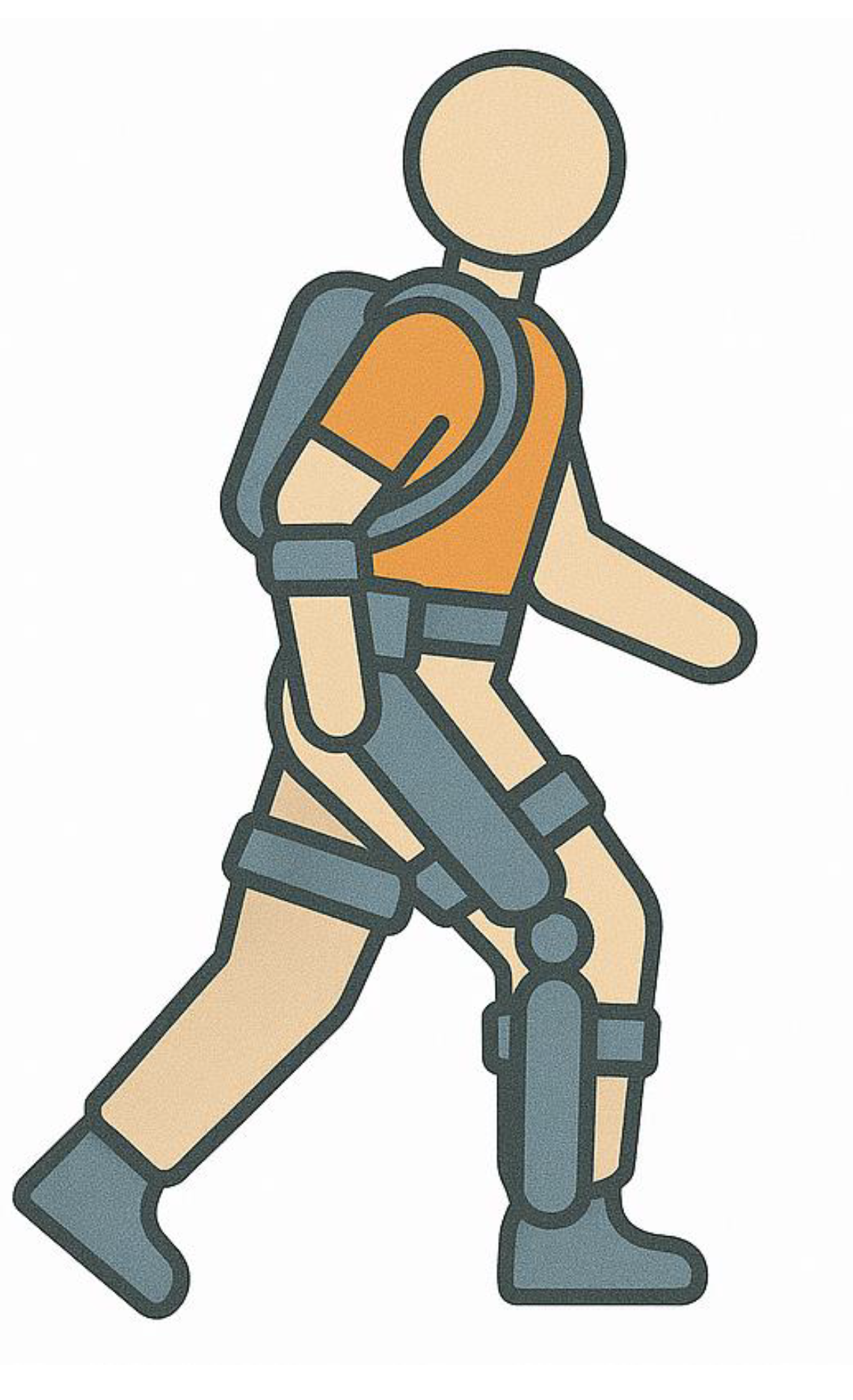
EXPO and SUBAR are mobile systems consisting of a motorized base and a wearable unit. They use Bowden cable transmission to reduce the load on the user. EXPO delivers up to 44 Nm torque compared to SUBAR’s 7.7 Nm and includes impedance compensation for smoother interaction [29,30].
AssistON-Gait provides active pelvis and hip support using six DOFs and series elastic actuators. It emphasizes ergonomic, back-drivable joints with self-alignment [31].
Walking Assistance Device, designed by Ikehara et al., uses backpack-mounted actuators to power ankle and knee joints. EMG analysis showed reduced muscle activity in healthy users wearing the system [32].
- Intelligent and Hybrid Systems
HAL (Hybrid Assistive Limb) is notable for combining passive trajectory playback and sEMG-based intention detection. It is available in various configurations (full-body, single-leg, etc.) and uses DC servomotors with harmonic drives for joint actuation [33,34,35,36].
XoR is another intelligent hybrid system utilizing both pneumatic and electric actuators. It estimates user intent based on joint angles, ground reaction forces, and EMG data, and targets posture control and rehabilitation in elderly users [37].
CUHK-Exo applies a human-robot eight-link dynamic model and hybrid control to assist sit-to-stand transitions and walking. Tested on both paraplegic and healthy subjects, it emphasizes real-world usability [38].
- Systems for Spinal Cord Injury and Severe Impairments
Vanderbilt Exoskeleton supports multiple tasks including walking, stair climbing, and sitting using pre-recorded gait trajectories. It includes speech-to-text functionality and supports users up to 200 pounds [39]
MINA, co-developed by NASA and IHMC, uses rotary series elastic actuators and supports walking at 0.2 m/s after training. It offers three active DOFs and passive balancing using crutches [40].
WPAL focuses on compliance control using joint velocity and interaction force data to calculate assistive torque dynamically [41].
MindWalker supports user-initiated walking through recorded gait data. It provides three active and two passive DOFs and uses an extrapolated center of mass (XCoM) model to enhance lateral stability [42].
ABLE integrates a powered orthosis, foot-mounted platform, and crutches. Each module works independently or in combination, with assistance levels based on a quasi-static human model [43].
Ortholeg and Ortholeg 2.0 introduce eye-controlled movement for spinal cord injury patients. Ortholeg 2.0 is ergonomically enhanced and more durable [44,45].
Yonsei University's Exoskeleton is the first to use center of pressure (CoP) feedback to enable self-balancing. With 14 DOFs and real-time force sensing, it enhances safety and gait realism [46].
WWH (Wearable Walking Helper) offers gravity compensation using a body model. Effectiveness has been validated via EMG and heart rate measurements across different tasks [47,48,49].
A comparative study among the various developed human lower extremity exoskeleton robots are shown in Table 1
In summary, Treadmill-based systems offer precise, structured training environments suited for early rehabilitation, while mobile exoskeletons provide versatility for real-world walking and posture training. Among mobile systems, modularity, control intelligence (e.g., sEMG, CoP, XCoM), and ergonomic design continue to evolve to meet the needs of diverse patient populations. The integration of adaptive control, sensor fusion, and user-intent recognition is central to next-generation exoskeleton development.
The existing literature underscores the significance of human lower extremity rehabilitation exoskeleton robots. However, an analysis of current designs reveals a critical limitation: most exoskeletons lack flexibility at the interface between the robotic links and the human body attachments, which results in additional pressure on the user’s limb. To address this issue, we developed a novel mechanism that introduces controlled flexibility, particularly at the shank segment. The knee joint, being biomechanically complex with both rotational and translational components, requires such adaptability for natural and safe movement. The proposed mechanism accommodates these motions, thereby reducing undesired stress on the user’s limb. Additionally, we incorporated an adjustable link-length arrangement, enabling the same exoskeleton to be used by individuals of varying heights, thus improving adaptability and usability across diverse patient populations.
- Control Strategies for Lower Limb Exoskeletons
The control of lower limb exoskeletons is challenging due to nonlinear dynamics, actuator constraints, and variability in human-robot interaction. The literature shows a clear progression from simple linear controllers to robust, adaptive, and intelligent approaches. There are various types of control algorithms that have been developed over time which include linear, nonlinear, adaptive, impedance and intelligent control algorithms. Every control scheme has its own strengths and limitations. Table 2 discuss various control techniques commonly used in rehabilitation robotics, their strengths and limitations.

Table 2.
List of various control techniques recently used in human lower extremity exoskeleton robots.
Table 2.
List of various control techniques recently used in human lower extremity exoskeleton robots.
| Method | Strengths | Limitations | Ref. |
|---|---|---|---|
| PD / PID | Simple, fast to implement | Poor robustness; sensitive tuning | [63] |
| Impedance / Admittance | Safe, compliant human–robot interaction | Requires accurate force sensing | [64,65] |
| Conventional SMC | Robust to uncertainties | Severe chattering | [66] |
| Adaptive Control | Robust to uncertainties and parameter variation | Require extensive computation | [67] |
| Adaptive SMC | Smooth torque; robust trajectory tracking | Algorithmic complexity | [68] |
| Fuzzy / Neural Hybrid SMC | Handles nonlinearities and uncertainties | Higher computational load | [69] |
| Reinforcement Learning (RL) | Learns personalized control policies | Data-intensive; training stability | [70] |
| Prescribed Performance Control | Guarantees bounded error | Limited flexibility | [71] |
| SEA + Continuous SMC | Reduces chattering; improves compliance | Complex actuator design | [72] |
| Data-Driven Predictive Control | Payload-robust; adaptive to variability | High computation demand | [73] |
| EMG-driven Adaptive Control | Intention-driven; promotes active therapy | Signal noise; electrode issues | [74] |
Among the different control schemes, based on the strength and limitation Sliding Mode Control (SMC) was selected for the developed lower extremity exoskeleton robot that face uncertainties, disturbances, and nonlinear dynamics. Exoskeletons interact directly with the human body, meaning that the dynamics vary widely from user to user due to differences in body mass, gait, and muscle strength. SMC is particularly valuable here because it guarantees system stability and reliable performance even when the model is not perfectly known or when there are external disturbances.
Another reason for using SMC is its strong tracking ability. Once the system state reaches the sliding surface, it remains there and follows the desired trajectory with high accuracy, which is critical for rehabilitation or mobility assistance where precise joint movement ensures safety and therapeutic effectiveness. SMC also has a relatively simple design principle, as the control law is derived from Lyapunov stability theory, making it easier to ensure mathematical guarantees of stability compared to many adaptive or learning-based methods.
- Adaptive Sliding Mode Control (ASMC)
Adaptive Sliding Mode Control (ASMC) has emerged as a powerful extension of classical Sliding Mode Control (SMC), offering enhanced performance in the control of human lower extremity exoskeletons and other complex robotic systems. Traditional SMC is widely recognized for its robustness against model uncertainties, parameter variations, and external disturbances; however, its reliance on fixed control gains and the notorious chattering phenomenon often limit its practical deployment in wearable robotics. ASMC addresses these shortcomings by integrating adaptive mechanisms that dynamically tune control parameters in real time, thereby improving both robustness and flexibility.
A significant advantage of ASMC is its reduced dependency on accurate system modeling. Exoskeleton dynamics are inherently nonlinear and subject to user-specific variations, including differences in body mass, gait patterns, and rehabilitation progress. By adaptively estimating uncertain parameters and compensating for time-varying dynamics, ASMC ensures reliable performance without the need for exhaustive modeling. This capability is especially critical for rehabilitation contexts, where personalized adaptability is necessary to provide safe and effective assistance across diverse patient populations [68].
Another notable strength of ASMC is its ability to mitigate the chattering problem inherent in conventional SMC. Through adaptive gain adjustment or boundary layer methods, ASMC smoothens the control signals while maintaining robustness. This results in reduced actuator wear, improved energy efficiency, and enhanced user comfort. Smooth control actions also contribute to safer and more natural human–robot interaction, which is a key consideration in clinical and daily-use exoskeletons. Furthermore, ASMC enhances trajectory tracking accuracy by ensuring that the tracking error converges to a small neighborhood of the desired trajectory. Such precision is essential in rehabilitation training, where accurate joint motion can directly influence therapeutic outcomes.
Beyond robustness and accuracy, ASMC offers advantages in terms of energy efficiency and scalability. By automatically tuning control gains according to system requirements, ASMC minimizes excessive control effort, thereby conserving energy. Additionally, ASMC scales effectively to multi-degree-of-freedom (DOF) systems, maintaining stability and robustness across multiple joints simultaneously. This makes it a practical and versatile solution for whole-leg exoskeletons designed to support walking, stair climbing, and complex gait transitions.
3. Biomechanical Modeling
Accurate biomechanical modeling is essential in biorobotics, serving as the analytical foundation for high-precision control, realistic simulation, and physiologically consistent system design. The modeling framework adopted in this study is organized around three fundamental components: kinematic modeling, dynamic modeling, and friction modeling, each capturing distinct yet interrelated aspects of mechanical system behavior.
Kinematic modeling describes the motion of the system in terms of joint positions, velocities, and accelerations, independent of the forces that generate them. In this work, the Denavit-Hartenberg (D-H) convention is used to parameterize the spatial transformations between adjacent links, allowing systematic representation of joint configurations and limb geometry. This facilitates the computation of forward and inverse kinematics necessary for motion planning and control.
Dynamic modeling builds upon the kinematic framework by incorporating mass distribution, segmental inertia, and external forces to quantify how the system responds to control inputs. A Lagrangian formulation is employed to derive the equations of motion, accounting for kinetic and potential energy contributions from both the exoskeleton and the human limb. This formulation inherently incorporates gravitational, Coriolis, and inertial effects, enabling accurate computation of joint torques under varying task loads and trajectories.
Friction modeling addresses the nonlinear resistive forces arising from joint interfaces, actuators, and transmission elements. In this study, the LuGre dynamic friction model is implemented to capture both static and dynamic friction characteristics, including Stribeck effects, pre-sliding displacement, and velocity-dependent behavior. Precise friction modeling is particularly important for replicating human-exoskeleton interactions during low-velocity transitions, such as gait initiation or postural adjustments.
Collectively, these components form a physically coherent and computationally tractable modeling framework that supports both simulation-based validation and model-based control. The exoskeleton’s dynamic model is developed to reflect the coupled behavior of the robotic system and the human musculoskeletal structure. Given that the exoskeleton operates in parallel with the user’s lower limb, it is imperative to integrate the mass, inertial properties, and joint biomechanics of both systems. Accurate modeling of these parameters ensures that the control actions are physiologically relevant and safe for the user.
To achieve accurate modeling, detailed anatomical knowledge of the lower extremity is integrated, including joint architecture, segment lengths, and center-of-mass locations. This information is incorporated using subject-specific anthropometric data. The resulting hybrid dynamic model supports real-time estimation of joint torques and interaction forces, providing a foundation for implementing advanced control strategies such as optimized sliding mode control scheme for human lower extremity rehabilitation.
The following sections offer a comprehensive overview of the human lower extremity’s kinetics, define segmental mass and inertia parameters, and present the integrated kinematic and dynamic modeling of the lower limb exoskeleton.
3.1. Overall System Architecture
The exoskeleton features a modular, vertically supported structure mounted on a mobile base platform. The lower steel plate provides structural stability and mobility through four caster wheels. A vertically adjustable upper plate, actuated by a lead screw mechanism, allows height alignment of the limb modules with the user’s hip joint. The leg mechanism is composed of four actuated joints arranged in series, corresponding to the hip, thigh, knee, and ankle. Each DOF is driven by a dedicated brushless DC motor, with appropriate linkage mechanisms such as pantograph structures and four-bar linkages to accommodate anthropometric variability and replicate human joint trajectories. The system is fully modular, enabling individual joint calibration, rapid setup, and future extensibility.
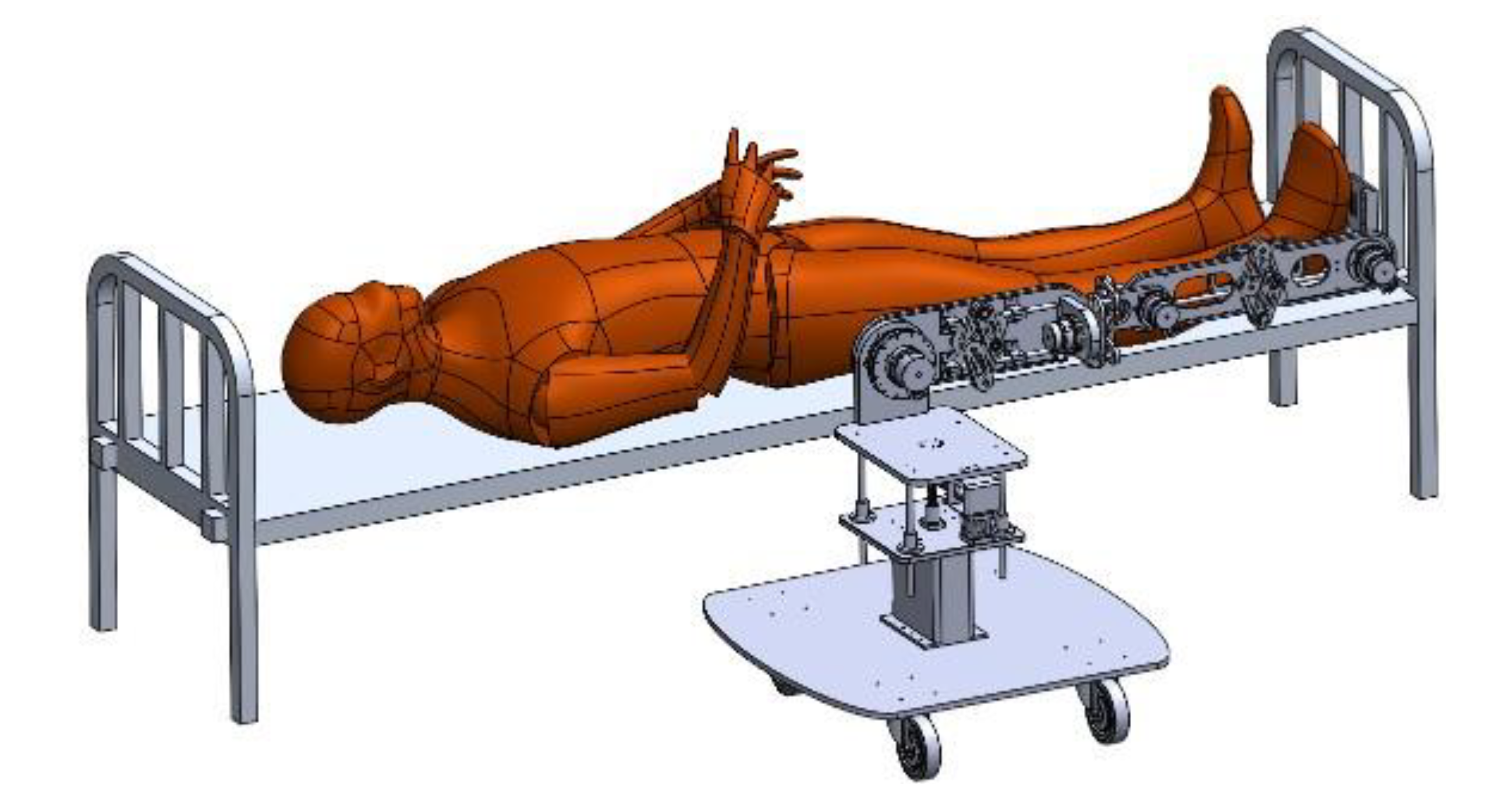
Figure 3.
Complete model of the human lower extremity exoskeleton robot.
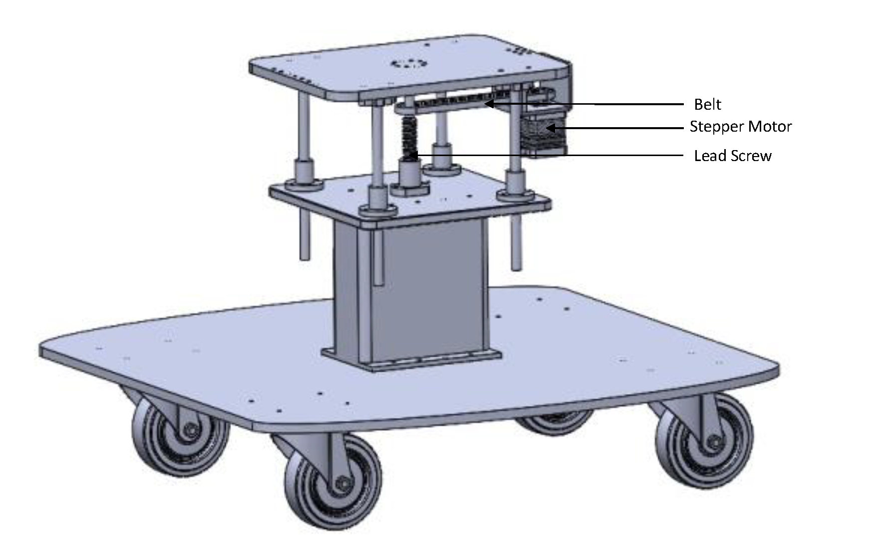
Base Platform and Support Structure
The foundation of the lower extremity exoskeleton system is a robust mobile platform designed to provide stability, ease of transport, and vertical adjustability for alignment with users of varying anthropometric dimensions. The platform consists of two structural levels: a lower steel base plate equipped with caster wheels, and an upper adjustable plate that serves as the mounting interface for the leg mechanism. The lower base plate is fabricated from steel to ensure a low center of gravity and to withstand the reaction forces generated during rehabilitation exercises. It is supported by four caster wheels, enabling mobility and ease of repositioning in clinical environments. A vertical steel column is rigidly fixed to the lower base plate and extends upward to support the actuation and linkage assembly. At the top of this column, an upper platform is mounted using four linear guide shafts with linear bearings, allowing vertical translation while maintaining horizontal stability. The vertical motion of the upper plate is achieved using a lead screw mechanism, centrally aligned and driven by a stepper motor. A belt and pulley transmission system are employed between the stepper motor and the lead screw. This arrangement allows compact placement of the motor and offers smoother engagement and mechanical protection. This configuration allows precise height adjustment of the exoskeleton’s joint modules to match the user’s hip height, ensuring proper anatomical alignment. The stepper motor provides fine control over positioning, and the lead screw converts rotary motion into backlash-minimized linear displacement. Guide rods provide additional structural stiffness and vibration damping during adjustment.
Figure 2.
Exoskeleton Robot Base.
Hip Flexion/Extension Mechanism
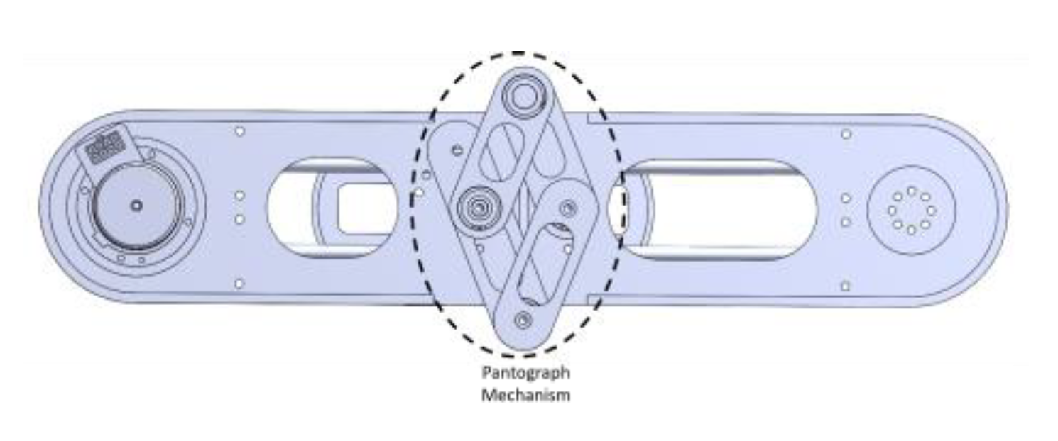
The hip flexion/extension (F/E) mechanism is responsible for replicating sagittal plane motion of the human hip joint, enabling forward and backward leg. This actuation module is mounted on the vertically adjustable top plate of the support structure and forms the proximal interface between the exoskeleton and the user’s thigh segment. A brushless DC motor is used to drive the hip F/E movement. The motor is securely mounted on a vertical bracket and delivers rotational torque directly to the thigh linkage. The mechanical layout ensures alignment of the motor’s axis of rotation with the anatomical hip joint to avoid kinematic mismatch and reduce unintended joint loading during therapy. A key feature of this mechanism is the integration of a pantograph-type length adjustment system along the thigh link. This mechanism is designed to accommodate users with varying femur lengths without requiring reconstruction of the frame. The pantograph consists of two parallel rigid arms connected by a central linkage, which preserves the rotational symmetry and geometry of the leg while allowing for length variability. Each pivot point of the pantograph is supported by high-precision bearings to ensure smooth transmission. The pantograph structure is mounted on two linear guide rods which provide translational guidance during length adjustment. The bottom plate beneath the pantograph includes a series of pre-drilled mounting holes, enabling the clinician to lock the pantograph at discrete positions based on the user’s thigh length. Once the desired length is achieved, the mechanism is fastened using screws through the designated holes, ensuring structural rigidity and motion fidelity. The dual-plate configuration with rigid anchoring, combined with the pantograph adjustability, offers both mechanical robustness and user-specific rehabilitation.
Figure 3.
HIP Flexion/Extension Mechanism (Front).
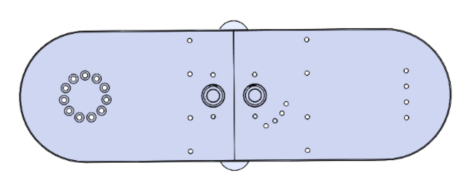
Figure 4.
HIP Flexion/Extension Mechanism (Back).
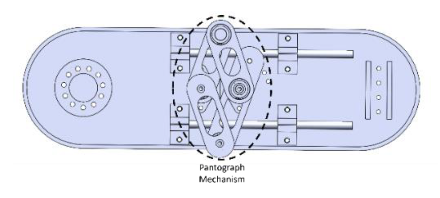
Hip Internal/External Rotation Mechanism
The hip internal/external (I/E) rotation mechanism enables axial rotation of the entire lower limb and is placed between the hip flexion/extension and knee flexion/extension joints. This degree of freedom is essential for transverse plane movement during rehabilitation, especially for activities involving turning, pivoting, or aligning the lower limb to reduce compensatory motion.
The rotation is achieved using a symmetric four-bar linkage driven by a motor coupled to the input link. The mechanism comprises:
- A fixed base link (mounted to the hip segment),
- An input link (connected to the motor shaft),
- A pair of parallel coupler links,
- And an output plate (which transmits the rotation to the knee-ankle section).
The motor rotates the input plate, which in turn drives the entire four-bar assembly. This motion causes the output plate which is rigidly attached to the next joint module to rotate in the same direction. To maintain symmetry and torque balance, the mechanism uses two sets of parallel arms on either side of the central axis. These are connected via bearings mounted on guide rods, enabling smooth, stable, and constrained rotation. The structure is mechanically closed-loop, ensuring the motion of the output link mirrors that of the input without slippage or misalignment. The design avoids the use of long shafts or universal joints and distributes loading evenly across the linkage. It is compact, rigid, and well-suited for modular integration within the exoskeleton’s lower limb structure.
Figure 5.
Hip Rotation Mechanism.
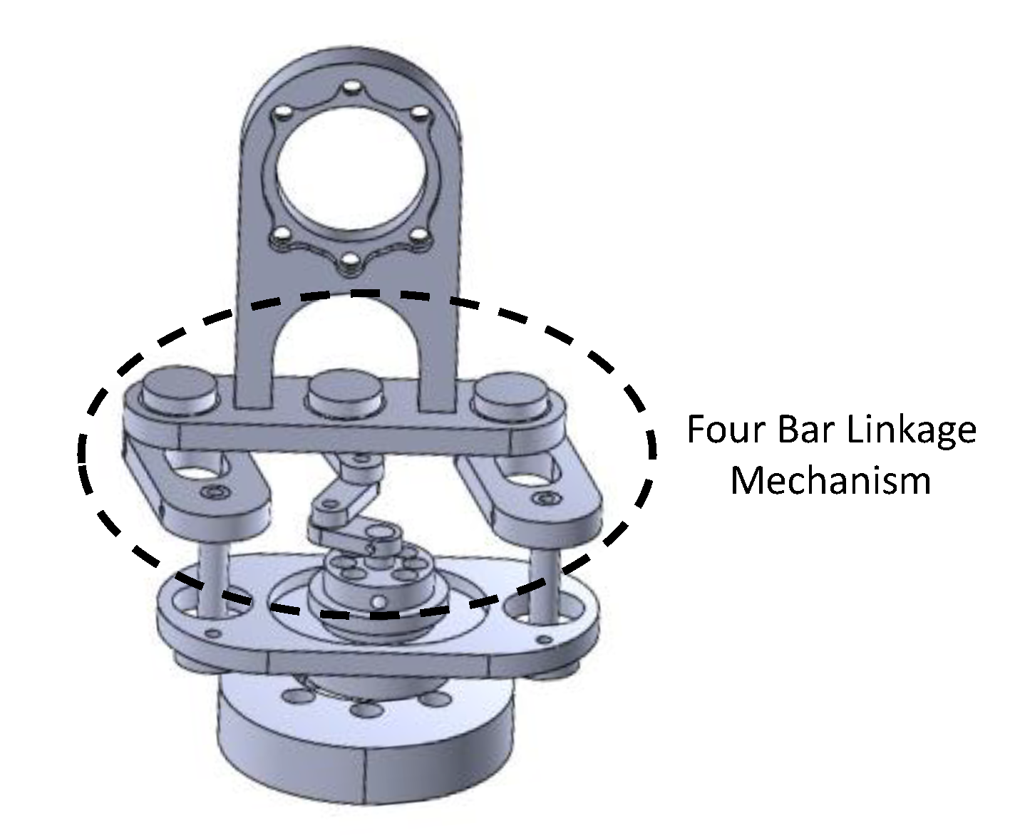
Knee Flexion/Extension Mechanism
The knee flexion/extension mechanism enables sagittal plane motion of the leg, replicating the primary movement of the human knee joint. The actuation is performed using a brushless DC motor mounted on the femoral link, driving the tibial segment via a rigid rotary connection. The configuration is similar to the hip F/E unit and includes a pantograph linkage to allow structural adaptability. To more accurately model human knee biomechanics, the design integrates a passive linear displacement mechanism. During natural knee flexion, the joint's instantaneous center of rotation shifts, producing a combined arc-and-slide movement. To capture this, the tibial section includes a sliding plate that translates along two parallel steel guide rods. This plate is mounted on linear bearings, allowing it to move freely in response to the angular motion initiated by the actuator. As the knee rotates, the follower plate glides smoothly along the rods, introducing a controlled linear shift that mimics the femoral rollback seen in human gait. The mechanism is fully mechanical. So, no secondary actuation is required which helps reducing misalignment-induced strain. This hybrid approach of combining rotary actuation with guided linear translation improves comfort, joint alignment, and rehabilitation effectiveness.
Figure 6.
Knee Flexion-Extension Mechanism (Front).
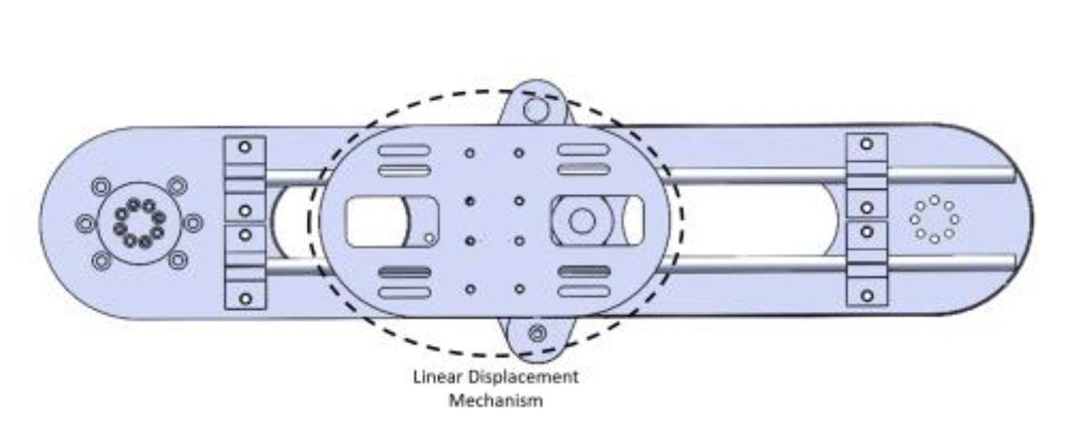
Figure 7.
Knee Flexion-Extension Mechanism (Back).
Ankle Flexion/Extension Mechanism
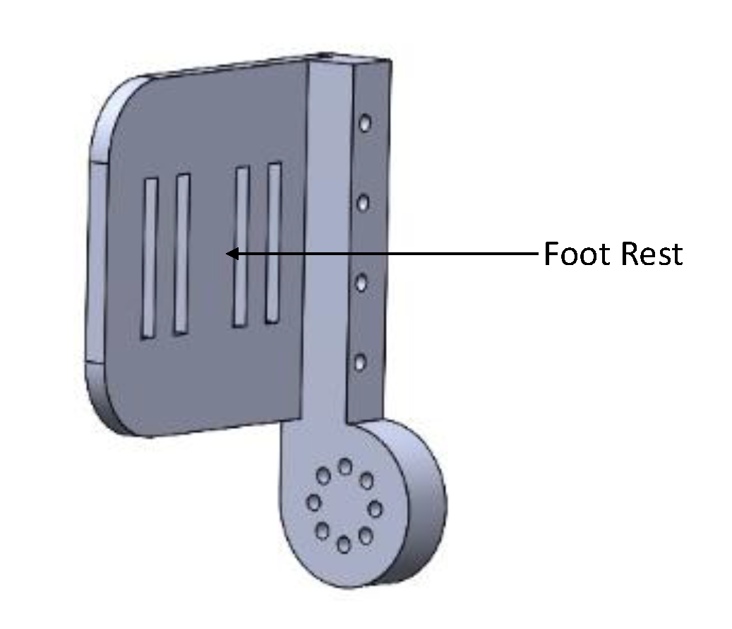
The ankle flexion/extension (F/E) mechanism enables dorsiflexion and plantarflexion, mimicking the pitch motion of the human ankle joint. It is located at the distal end of the exoskeleton’s shank segment and interfaces with the foot support bracket. The motion is actuated by a brushless DC motor mounted horizontally and directly aligned with the ankle joint axis. The motor drives a rigid coupling that rotates the attached foot link. This configuration enables smooth angular displacement of the foot plate relative to the shank, facilitating ankle movement during rehabilitation exercises. The foot bracket is a vertically elongated, curved structure designed to securely support the user’s foot. It includes a slotted cutout to reduce weight and allow for mounting adjustments. The user's foot is strapped or fastened directly onto this bracket. The bracket rotates together with the motor output, thus enabling flexion and extension at the ankle joint. The ankle assembly is structurally integrated into the main leg linkage, and its alignment ensures that the motor axis corresponds closely to the anatomical ankle pivot point. This joint completes the four-DOF actuation scheme and allows for ankle movement training in a bed-supported posture.
Figure 8.
Ankle Flexion-Extension Mechanism.
3.2. Actuation System
The actuation system of the exoskeleton is built around a modular assembly combining a Maxon BLDC motor with a Harmonic Drive gear unit. This combination offers high torque output, compact packaging, and zero backlash, which are the key features for precision joint control in rehabilitation. The motor is coupled to the gearbox using a rigid connector, which transmits torque while maintaining alignment. The output shaft and flange components are custom-designed to securely transfer torque to the joint structure while ensuring alignment with surrounding linkages. Bearings are integrated to support radial loads and minimize wear, ensuring long-term durability. The larger flanges and shaft adaptors allow modular connection between the actuator and joint-specific components, streamlining assembly and maintenance. This motor-gear arrangement is used across all major joints and enables consistent performance. The structure supports both position and torque control, making it suitable for adaptive and safe human-robot interaction during rehabilitation.
3.3. Sensor Integration
Brushless DC (BLDC) motors often come equipped with built-in Hall effect sensors to provide rotor position feedback, which is essential for precise electronic commutation. These sensors are typically embedded at 120-degree electrical intervals within the stator and detect the magnetic field generated by the rotor's permanent magnets. As the rotor rotates, the sensors output digital signals that indicate the rotor’s position relative to the stator windings. This information enables the motor controller to determine the appropriate timing and sequence for energizing the motor phases, ensuring efficient and smooth rotation. In exoskeleton and robotic applications, BLDC motors with Hall effect sensors are particularly advantageous, as they allow for closed-loop control, improved low-speed performance, and reliable start-up without requiring complex sensorless estimation algorithms. Additionally, the compact integration of sensors within the motor housing reduces system complexity and wiring, contributing to a more streamlined and maintainable actuation system.
3.4. Safety and Comfort Considerations
To ensure comfort, adaptability, and safety across a wide range of users, the exoskeleton system was designed with several user-centered mechanical features. Soft padding was incorporated at all major contact points to reduce pressure on the skin and enhance user comfort during extended use. Adjustable link lengths allowed the exoskeleton to accommodate users of different heights and limb proportions, ensuring proper alignment with anatomical joints and minimizing the risk of joint misalignment. Mechanical joint stops were integrated to restrict motion within physiologically safe ranges, preventing hyperextension or unnatural limb movement. Additionally, safety interlocks and software-defined torque limits were implemented to detect abnormal operating conditions and limit actuator output, thereby protecting users from overexertion or injury. These features collectively enhanced the system’s usability, safety, and therapeutic effectiveness in clinical and assistive settings.
4. Dynamic Modeling of a Lower Extremity Exoskeleton Robot for Rehabilitation
Accurate biomechanical modeling serves as a critical foundation in the design and control of rehabilitation robotics. In this study, we present an integrated modeling framework for a four-degree-of-freedom (4-DOF) lower extremity exoskeleton system developed for gait training and motor recovery. The framework is composed of three primary components: kinematic modeling, dynamic modeling, and friction modeling.
Kinematic modeling characterizes the motion of the exoskeleton joints independent of the forces involved. Using the Denavit–Hartenberg (D–H) convention, we parameterize the spatial relationships between adjacent links, enabling efficient derivation of forward and inverse kinematics. This structured approach supports real-time motion planning and controller synthesis.
Dynamic modeling incorporates mass distribution, inertia, and external forces to describe the motion of the coupled human-exoskeleton system. We use a Lagrangian formulation to derive the equations of motion, which account for kinetic and potential energies from both the exoskeleton and the human limb. This formulation includes gravitational, Coriolis, and inertial terms and is essential for torque estimation and controller development in variable-load tasks.
Friction modeling captures the nonlinear resistive forces present in actuators and mechanical joints. We adopt a hybrid friction model that combines Coulomb, viscous, and Stribeck effects to replicate both static and dynamic behaviors. This model is computationally efficient and suitable for real-time compensation. It is equivalent in structure to the LuGre model and is critical for modeling interactions during low-velocity tasks such as postural transitions and gait initiation.
Together, these components produce a hybrid model that fuses the mechanical properties of the exoskeleton and the human lower limb, enabling physiologically meaningful torque control and safe, adaptive rehabilitation strategies.
4.1. Anatomically Informed Design Considerations
To ensure functional alignment with human biomechanics, the exoskeleton design process is grounded in detailed anatomical analysis. This includes identifying joint degrees of freedom, range of motion constraints, and segmental anthropometry. These insights directly inform the kinematic structure and physical dimensions of the robotic limb.
Joint Range of Motion
Designing the exoskeleton to match human anatomy, we restrict motion to the four targeted DOF and the ROM in our table: hip flexion 0–20°, extension 0–45°, and axial internal/external rotation 0–20°/0–30°; knee flexion up to 90° with full extension at 0°; ankle dorsiflexion 0–30° and plantarflexion 0–45°. These limits set linkage geometry, actuator stroke, and hard-stop placement to avoid joint misalignment [73,74].
Table 2.
Range of Motion for the Exoskeleton.
| Joint | Motion | Range of Motion (°) | Description |
|---|---|---|---|
| Hip |
Flexion | 0° to 20° | Forward movement of the thigh (sagittal). |
| Extension | 0° to 45° | Backward movement of the thigh (sagittal). | |
| Internal Rotation | Up to 20° | Axial rotation of the thigh toward the midline. | |
| External Rotation | Up to 30° | Axial rotation of the thigh away from the midline. | |
| Knee |
Flexion | Up to 90° | Bending of the knee. |
| Extension | 0° (full extension) | Straightening of the knee to neutral. | |
| Ankle |
Dorsiflexion (Flexion) | Up to 30° | Foot moves toward the tibia. |
| Plantarflexion (Extension) | Up to 45° | Foot moves away from the tibia. |
Anthropometric Parameters
Anthropometric data informs link lengths, mass distributions, and inertial properties. On average, the thigh, shank, and foot represent 24%, 26%, and 15% of total body height, respectively. Their mass fractions are approximately 10–12% (thigh), 4–5% (shank), and 1.5–2% (foot). Centers of mass are located 43% (thigh and shank) and 50% (foot) from the proximal end. These values are used for accurate inertia and dynamic modeling [75,76].
Table 3.
Human lower extremity anthropometric parameters.
| Segment | Length (% of Body Height) |
Mass (% of Body Weight) |
Location of Center of Mass |
|---|---|---|---|
| Thigh | 24% | 10-12% | 43% from proximal end |
| Shank | 26% | 4-5% | 43% from proximal end |
| Foot | 15% | 1.5-2% | 50% from proximal end |
Anthropometric Parameters Estimation:
Inertial properties of each limb segment such as mass, center of mass (CoM), and inertia tensor are estimated using anthropometric scaling. Segment masses and lengths are calculated as fixed percentages of the subject’s total body mass and height, based on standard anthropometric values.
Since the CoM and inertia tensor depend on both mass and length, bilinear interpolation is used to estimate their values for any given segment. Reference values are prepared at four corner cases:
- Minimum mass and minimum length
- Minimum mass and maximum length
- Maximum mass and minimum length
- Maximum mass and maximum length
Here, m and l are defined as the segment’s mass and length
The CoM vector is estimated using:
The Inertia Tensor
Is Estimated Similarly
These values are used directly in energy and dynamics equations. This method allows smooth variation in inertial properties across different body sizes and improves the accuracy of dynamic modeling.
4.2. Kinematic Modeling
Kinematic modeling provides the foundation for motion analysis by relating joint variables to the position and orientation of the end-effector. In exoskeleton applications, it ensures the generated movement trajectories conform to physiological constraints and user-specific anatomy. The following sections cover the multiple steps involved in kinematic modeling.
We assign coordinate frames using the D-H convention with the following rules: the z-axis is aligned with the axis of joint rotation. The x-axis is orthogonal to adjacent and previous z-axes. The origin of each frame lies at the intersection of the x-axis and z-axis of the previous joint and the y-axis follows the right-hand rule. The Denavit–Hartenberg (DH) parameter definitions provide a standardized method to describe the relative transformations between adjacent links in a kinematic chain. For each link, four parameters are defined: , the angle of rotation about the axis required to align with ; , the linear offset along between the origins of frames and ; , the angle between and measured about the axis; and , the distance between the and axes measured along the axis. These parameters uniquely define the spatial relationship between successive joint frames in robotic manipulators.
Figure 9.
Schematic of the Lower Limb Exoskeleton with Joint Coordinate Frames.

Table 3.
DH parameters for the 4 DOF of Exoskeleton robot.
Forward kinematics establishes a mathematical relationship between the joint variables and the position and orientation of the end-effector relative to the robot’s base frame. The Denavit-Hartenberg parameters can be used to calculate the transformation matrices between each consecutive pair of links.
The general transformation matrix is shown in equation 1
The individual transformation matrices between the frames are shown in equation (2) to equation (7). For each link, the DH parameters has been substituted into the general form to get the transformation matrices:
The overall transformation matrix is obtained by multiplying the individual transformation matrics (Equation 2 to Equation 7):
The total transformation matrix T06 can be represented in the following form:
where:
are the elements of the rotation matrix describing orientation of the end effector frame with respect to the base frame.
are the coordinates of the end-effector position relative to the base frame.
Forward kinematics can be extended to the center of mass (COM) of each link, allowing for the computation of height from the base frame, which is essential for calculating potential energy.
4.3. Dynamic Modeling
The Jacobian matrix defines the relationship between joint velocities and the end-effector velocity. This relationship is expressed as , where is the end-effector velocity vector, is the Jacobian matrix, and is the vector of joint velocities.
Jacobian is critical for analyzing motion, identifying singularities, and developing dynamic control strategies. The general form of the Jacobian matrix can be presented as follows:
The Jacobian matrix can be evaluated at the COM to determine both linear and angular velocities, enabling accurate calculation of kinetic energy for each link.
The linear and angular velocities of each link's center of mass (COM) are calculated via Jacobians:
The dynamic behavior of a multi-degree-of-freedom (DOF) robotic exoskeleton can be modeled using the Euler-Lagrange framework. The standard equation of motion is given by:
where denotes joint positions, is the symmetric, positive-definite inertia matrix, represents Coriolis and centrifugal forces, is the gravity vector, and is the control input. These dynamics are highly nonlinear due to the configuration- and velocity-dependent terms in and , as well as nonlinear human-robot interaction forces. Such nonlinearities, compounded by uncertain user dynamics, make robust control design essential in rehabilitation robotics [1,2].
4.4. Friction Modeling
Friction is inherent in robotic manipulators and dissipates useful mechanical energy into heat and noise. Power transmission through components such as gearboxes, bearings, and seals introduces friction whenever relative motion occurs, with frictional torques reported to reach nearly 50% of transmitted torque [77]. Effective control strategies must therefore compensate for friction-induced disturbances.
Friction torque depends on factors including surface finish, relative velocity, lubricant viscosity, and temperature. Since these variables are interdependent and time-varying, accurate theoretical modeling is difficult, and most existing formulations are empirical. Classical models include Coulomb and viscous friction, the Stribeck effect, and hysteresis phenomena, while advanced approaches such as the LuGre, Dahl, and Karnopp models capture nonlinear and dynamic effects [78].
In this work, a combined model incorporating Coulomb friction, viscous friction, and the Stribeck effect is employed [79]. This representation is numerically equivalent to the LuGre model [80] and is used as the basis for subsequent analysis:
- Coulomb friction: Based on the Coulomb friction model, the friction torque is a constant quantity at any time.
- Viscous friction: Produces resistive torque proportional to the relative velocity between the contact surfaces.
- Stribeck friction (: The Stribeck effect models negatively sloped characteristics at low velocities.
Eqn. 21 presents the friction model. Eqn. 21 to Eqn. 23 are used to calculate the friction torque.
where,
is the total friction torque
is the Coulomb friction torque
is the breakaway friction torque: The sum of the Coulomb and Stribeck friction torques in the vicinity of zero velocity is often referred to as the breakaway friction.
is the breakaway friction velocity: The velocity at which the Stribeck friction is at its peak. At this point, the sum of the Stribeck and Coulomb friction is the breakaway friction torque.
is the Stribeck velocity threshold
is the Coulomb velocity threshold
is the input angular velocity
is the viscous friction coefficient: It is a proportionality coefficient between the friction torque and the angular velocity. The parameter value must be positive.
Figure 10 presents the relation between the angular velocity and friction torque in the combined friction model.
After considering the joint friction torques, the robot dynamics becomes
where,
Eqn. 20 can be written in the form of Eqn. 26
The next section will explain the developed Adaptive Sliding Mode controller with boundary layer based chattering supressor.
5. Advanced Sliding Mode Controller for Exoskeleton Robotics
Sliding Mode Control (SMC) is a discontinuous, nonlinear control technique that ensures system trajectories reach and remain on a designed sliding manifold, achieving desired performance despite bounded uncertainties [3]. Its key features include strong robustness to matched disturbances, finite-time convergence, and invariance of the reduced-order dynamics on the sliding surface. SMC requires limited model precision and is especially effective for systems with structured uncertainty.
Sliding Surface
The sliding surface for joint is defined as:
where:
is the position tracking error,
is the velocity tracking error,
is the sliding gain (here, ).
Design a Discontinuous Control Law
The control input is designed to make the sliding variable reach zero in finite time and stay there:
where,
: the equivalent control, designed from nominal dynamics (i.e., assuming perfect model)
: a positive gain large enough to overcome uncertainties
: the signum function, which causes the control to switch direction based on the sign of Once , the system "slides" along the surface, and the dynamics become insensitive to model uncertainties-a phenomenon called invariance.
Conventional Sliding Mode Control (SMC) offers several exceptional features that make it highly suitable for nonlinear and uncertain systems. It demonstrates strong robustness to parameter variations and external disturbances, ensuring reliable performance despite model inaccuracies. The method guarantees finite-time convergence, meaning the system reaches the sliding surface within a limited time. Once in sliding mode, the dynamics become insensitive to matched disturbances, maintaining control accuracy and stability. However, SMC also has notable drawbacks. The discontinuous sign function used in the control law can introduce high-frequency oscillations, known as chattering, which may damage actuators and degrade system performance. Additionally, the accuracy of the equivalent control component relies heavily on an accurate system model, and the controller is not well-suited for rejecting unmatched disturbances. In robotic applications, particularly in exoskeleton systems, SMC proves effective for managing complex nonlinear joint dynamics, compensating for unmodeled human-robot interactions, and ensuring robust joint trajectory tracking even under varying external conditions such as fluctuating loads or user-applied forces.
The Adaptive Sliding Mode Controller (ASMC) with a boundary layer-based chattering suppressor provides a notable improvement over conventional sliding mode control by addressing the issue of chattering while preserving robustness and fast convergence. In this method, the traditional discontinuous sign function is replaced with a continuous approximation, such as a saturation function, within a defined boundary layer around the sliding surface. This adjustment smooths the control signal as the system approaches the sliding surface, significantly reducing high-frequency oscillations that can damage actuators and affect system stability. Furthermore, the ASMC incorporates an adaptive gain mechanism that adjusts the control gain based on the magnitude of the tracking error or sliding variable. When the system is far from the desired trajectory, the gain increases to ensure rapid convergence, and as the error decreases, the gain reduces to minimize unnecessary control effort and torque spikes. By combining boundary layer smoothing with adaptive gain tuning, this controller achieves robust and accurate tracking performance while maintaining smooth actuation and protecting hardware. These features make the ASMC with boundary layer-based chattering suppression highly effective for real-world applications, particularly in rehabilitation and exoskeleton robotics, where reliable and safe interaction with the human body is essential.
The following section explains the development of the Adaptive Sliding Mode Controller (ASMC) with a boundary layer-based chattering suppressor.
Change in Sliding Surface Magnitude
The change in absolute sliding surface is computed as:
where is the previous sliding surface.
Adaptive Gain Update
The adaptive gain is updated based on the change in sliding surface:
with: : adaptation rates, minimum gain. Ensure:
Boundary Layer Saturation Function
The smoothed sign function (saturation) is defined as:
with:
boundary layer thickness.
Control Law
The control input for each joint is given by:
where:
scaling constant
Summary (for all Joints)
For each
To analyze the stability of the adaptive sliding mode controller (SMC) with boundary-layer-based chattering suppressor, we use Lyapunov stability theory. The controller adapts the gain based on the rate of change in the sliding surface and uses a boundary layer to smooth the control action.
Let the system dynamics be:
where:
: joint positions
control input
positive definite inertia matrix
Coriolis/centrifugal matrix
: gravity vector
Let the tracking error be:
Define the sliding surface:
with
Control Law
The control input is:
where is the sliding mode control term:
With gain update:
Lyapunov Candidate Function
Choose a Lyapunov function:
where is the ideal gain that compensates for disturbances.
Time Derivative of Lyapunov Function Differentiating :
Using the control law and robot dynamics:
Substitute:
Use property is skew-symmetric, hence: ⇒ can be Canceled or bounded Neglecting cross-terms or bounding them, we simplify:
Adaptive Gain Effect
When increases, ⇒ increase , increasing control authority to drive .
When decreases, ⇒ reduces control effort.
Stability Conclusion
Let Then:
Thus:
uniformly ultimately bounded (UUB) stability of Since asymptotic tracking
6. Simulation Results and Analysis
To assess the performance and robustness of different control strategies for a 5-degree-of-freedom (DOF) lower extremity exoskeleton robot, we conducted comprehensive simulations under various movement conditions. These strategies include:
- Conventional Sliding Mode Control (SMC) with sequential joint actuation
- Conventional SMC with simultaneous joint actuation
- Adaptive SMC with chattering suppressor during simultaneous actuation, and
- Adaptive SMC with chattering suppressor during sequential actuation.
Each control configuration was evaluated using trajectory tracking plots, tracking error dynamics, torque requirements, and adaptive gain behaviors where applicable. These results reflect the real-time response and control burden during typical rehabilitation motions, such as flexion-extension cycles in the hip, knee, and ankle joints. The control system’s ability to follow a reference trajectory with minimal error, limited control effort, and stable behavior is critical for ensuring patient safety and comfort during assisted movement therapy.
6.1. Conventional SMC – Sequential Joint Movements
Figure 12 through Figure 14 illustrate the system behavior under conventional SMC where each joint is actuated individually in a time-staggered sequence. This setup mimics isolated joint rehabilitation phases, such as early-stage motor training for a post-stroke patient where isolated muscle groups are targeted to reduce spasticity and initiate motor relearning.
In Figure 12, the reference and actual trajectories for all five joints show good alignment during their respective activation periods. This confirms that conventional SMC, known for its robustness against uncertainties and nonlinearities, is capable of stabilizing single-joint motions reliably.
Figure 12.
Trajectory tracking performance.
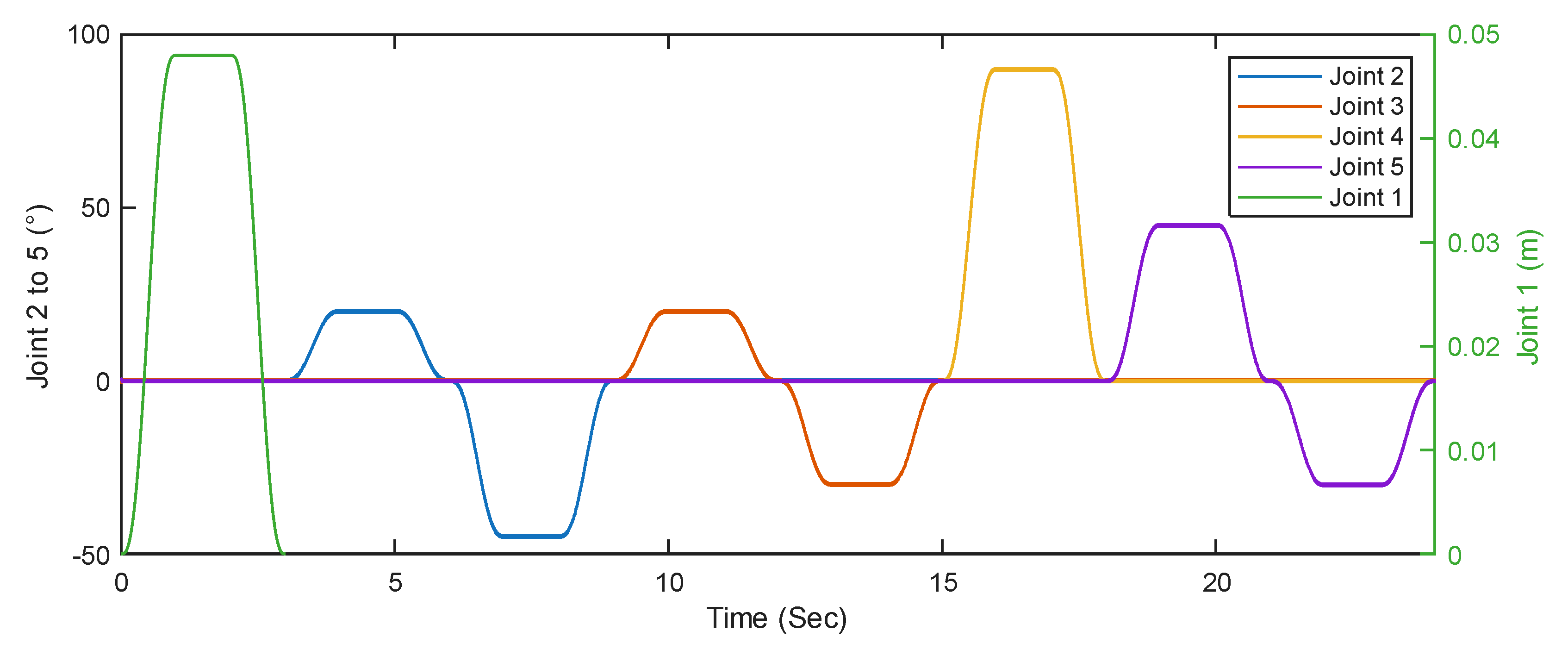
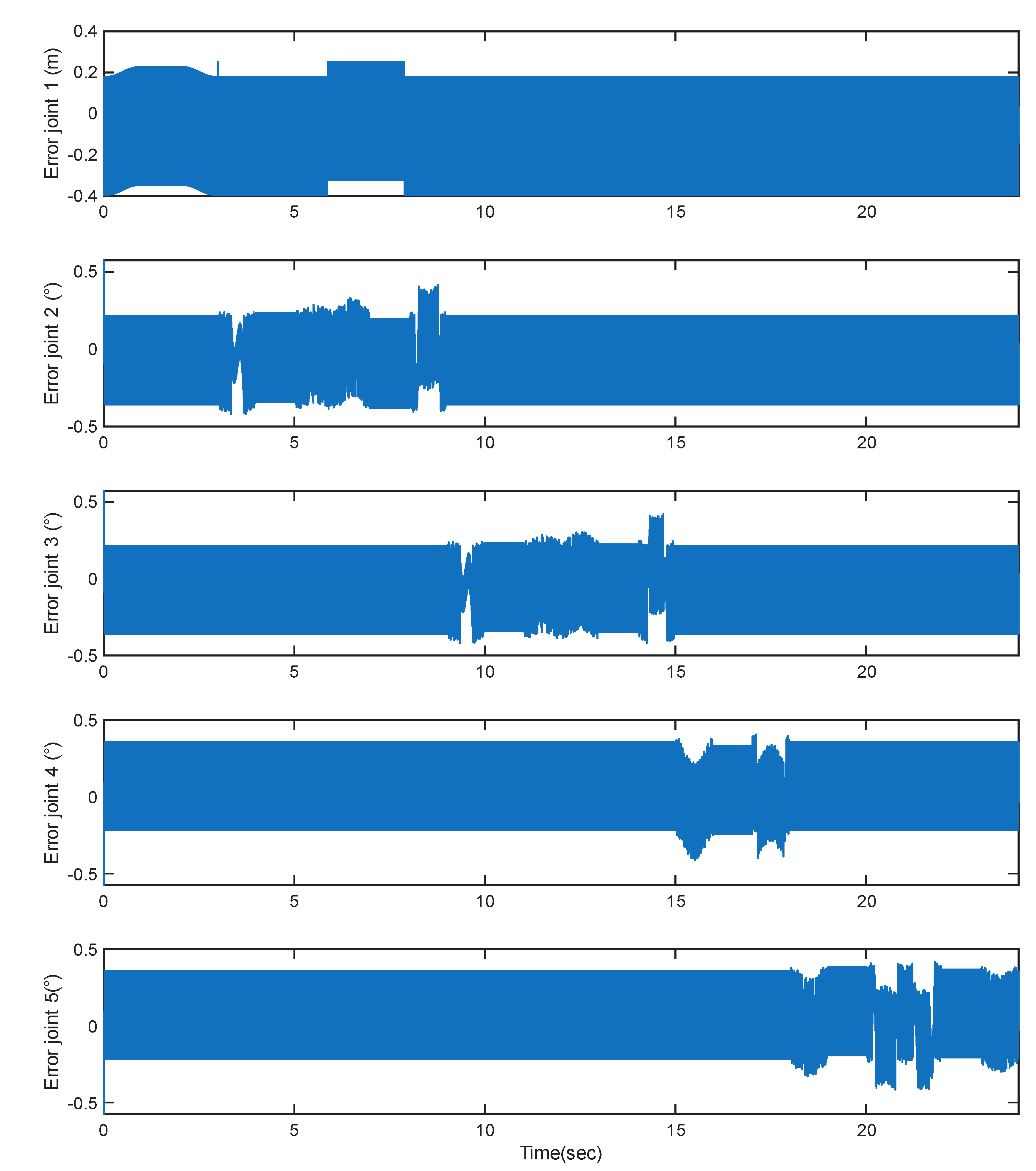
Figure 13 shows the trajectory tracking errors. Conventional Sliding Mode Controller tend to affect by chattering. It is clearly visible that joint 1 is highly affected by the chattering. The desired value of joint 1 is 0.048 m, it has been noticed that due to the effect of chattering the value cannot settle down at 0.048 m. Revolute joints (Joints 2 to 5) exhibit tracking errors up to ±0.5 degrees, while the prismatic joint (Joint 1) maintains errors within ±0.4 m. The average Root Mean Square Error (RMSE) across revolute joints is approximately 0.20 deg, indicating acceptable accuracy for isolated movements.
Figure 13.
Trajectory Tracking Errors.
Control torque profiles are shown in Figure 14 shows high-frequency oscillations, which are typical of classical SMC implementations due to the discontinuous control law.
Figure 14.
Joint Torques (Nm).
The peak torques using sliding mode controllers during the sequential joint movements are shown in Table 4:
Table 4.
Joint Force/Torque requirements.
| Joint Number | Peak force/torque | Average force/torque |
|---|---|---|
| Joint 1 | N | |
| Joint 2 | ||
| Joint 3 | ||
| Joint 4 | ||
| Joint 5 |
From the simulation it has been showed that the torque requirements are very high and also impractical. Torque profile involved a lot of chattering.
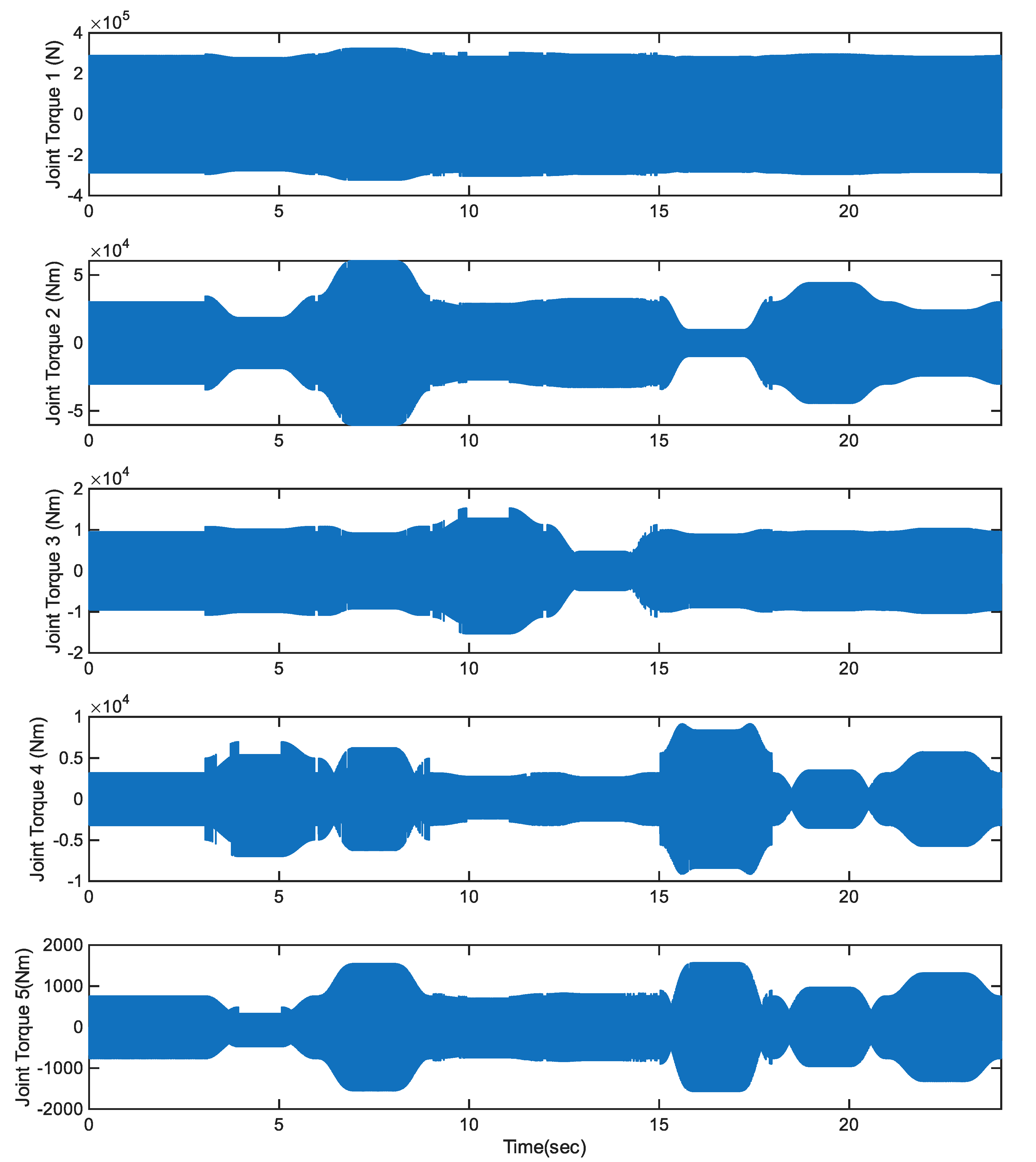
6.2. Conventional SMC – Simultaneous Joint Movements
Figure 15 through Figure 17 demonstrate the system's performance when all joints are actuated simultaneously using the same conventional SMC controller. This scenario closely resembles real-life walking or squatting movements, where coordinated joint actions are required to ensure dynamic balance and effective momentum.
As shown in Figure 15, the reference and actual trajectories are well-aligned, but the degree of tracking precision varies across joints. The revolute joints, particularly Joints 4 and 5, experience more significant deviations during high-speed transitions. The error plots in Figure 16 confirm these observations, revealing peak errors of up to [0.393°, 0.427°, 0.427°, 0.411°, 0.420°] degrees, and an average RMSE of 0.048 rad across all joints. These errors can be attributed to dynamic coupling effects between joints, which the fixed-gain SMC is unable to compensate for in real time.
Figure 15.
Trajectory Tracking Performance Simultaneous Joint Movements.
The torque profiles in Figure 6 reveal the key drawback of this configuration: aggressive and frequent switching actions that result in torque peaks up to Nm. The peak torques are verry high and impractical. In practical cases will cause actuator saturation alternatively.
Figure 16.
Trajectory Tracking Error.
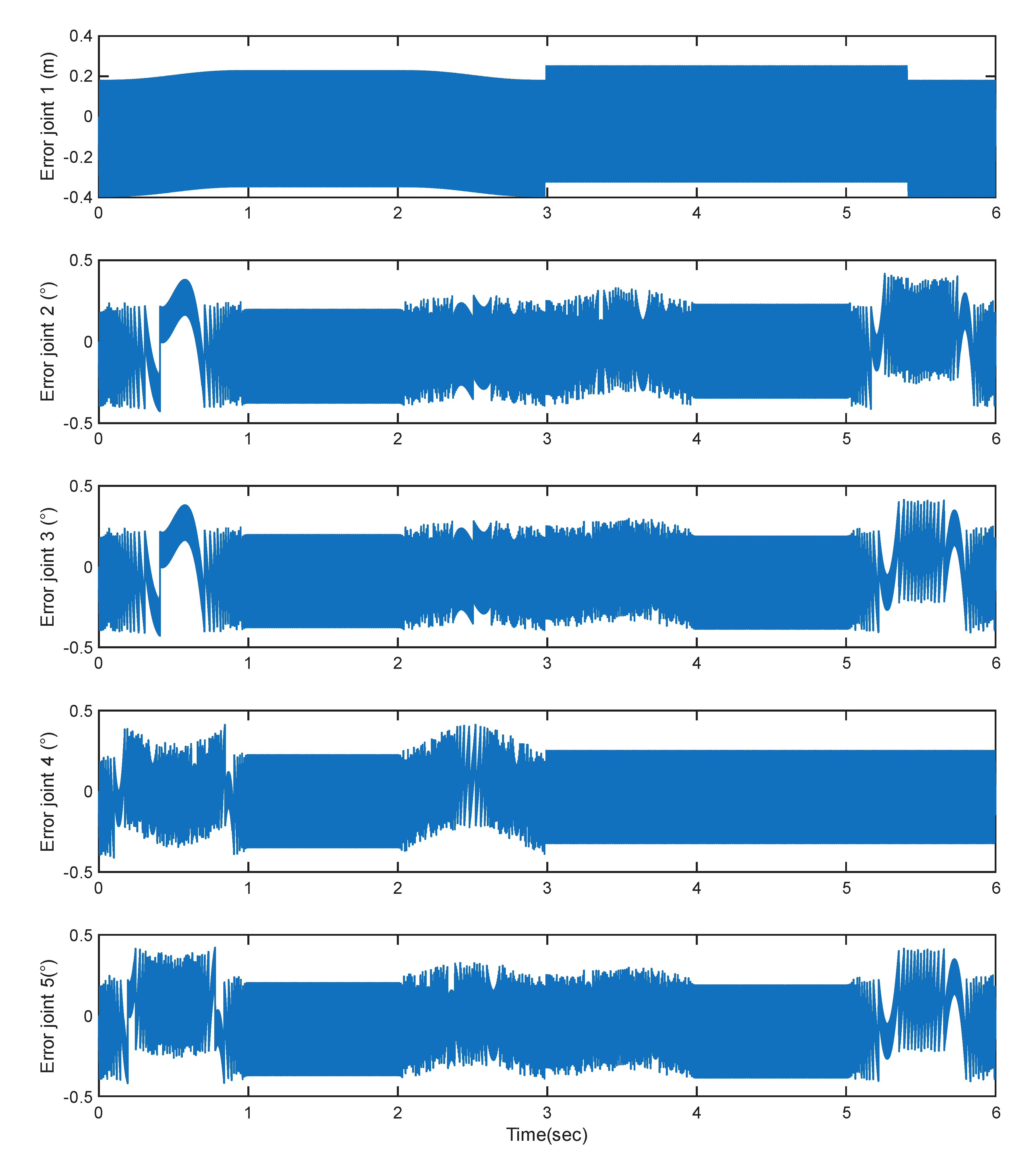
Figure 17.
Required Joint Torques.
Chattering is significantly more pronounced in this cases, raising concerns about actuator stress, potential joint wear, and reduced comfort during physical human-robot interaction. Although acceptable in terms of raw performance, this approach lacks the adaptability required for sensitive or long-duration rehabilitation sessions.
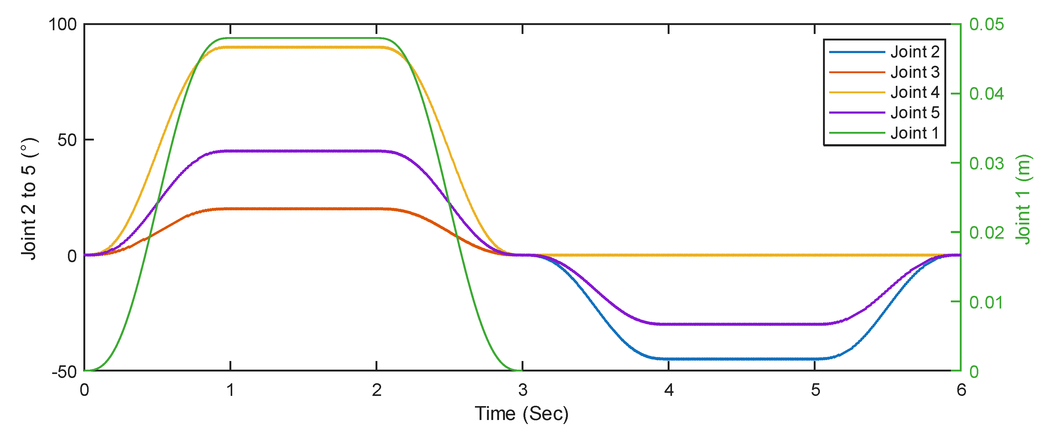
6.3. Adaptive SMC with Chattering Suppressor – Simultaneous Joint Movements
Figure 18 through Figure 20 present the performance of the Adaptive Sliding Mode Controller (ASMC) augmented with a boundary-layer-based chattering suppressor. This setup represents the advanced control scheme tested, combining sliding mode robustness with adaptive gain tuning and smooth torque generation to enhance safety and precision.
Figure 18.
Trajectory tracking performances.
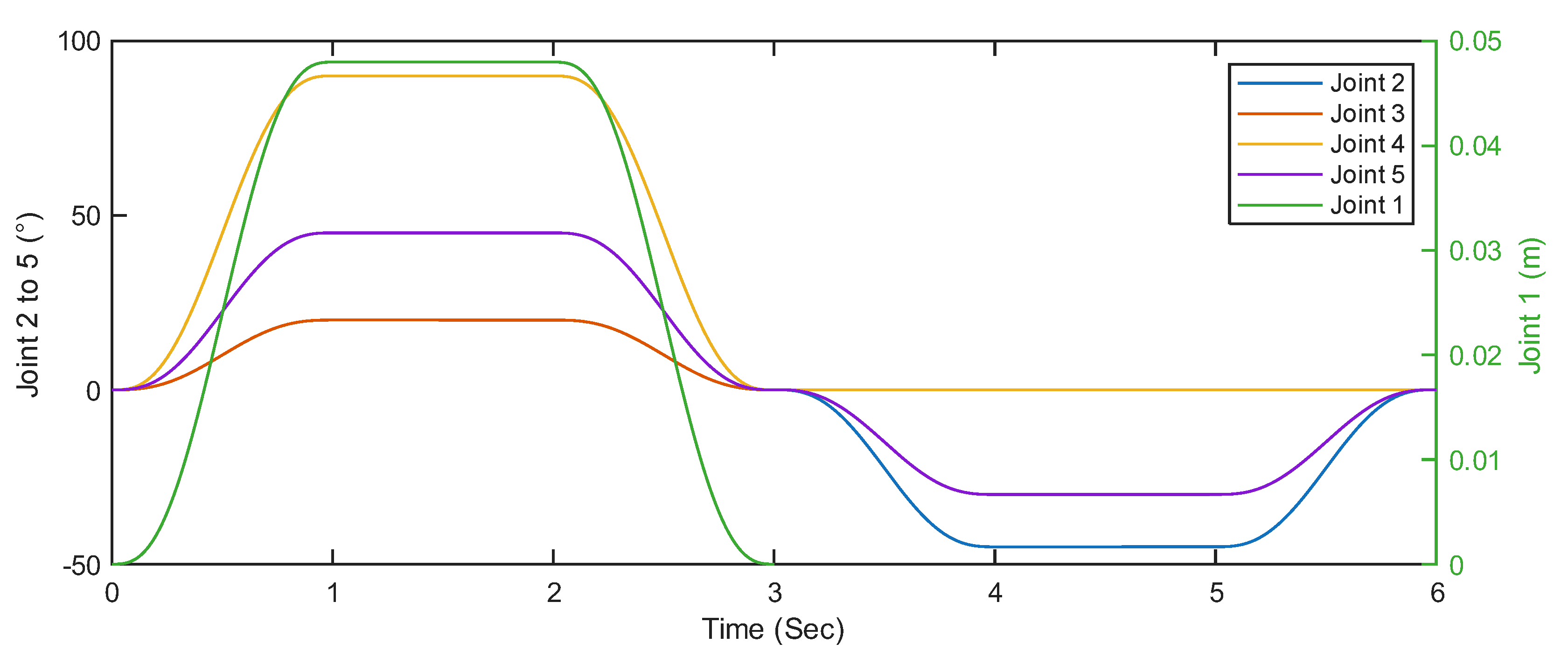
Figure 19.
Trajectory Tracking Errors.
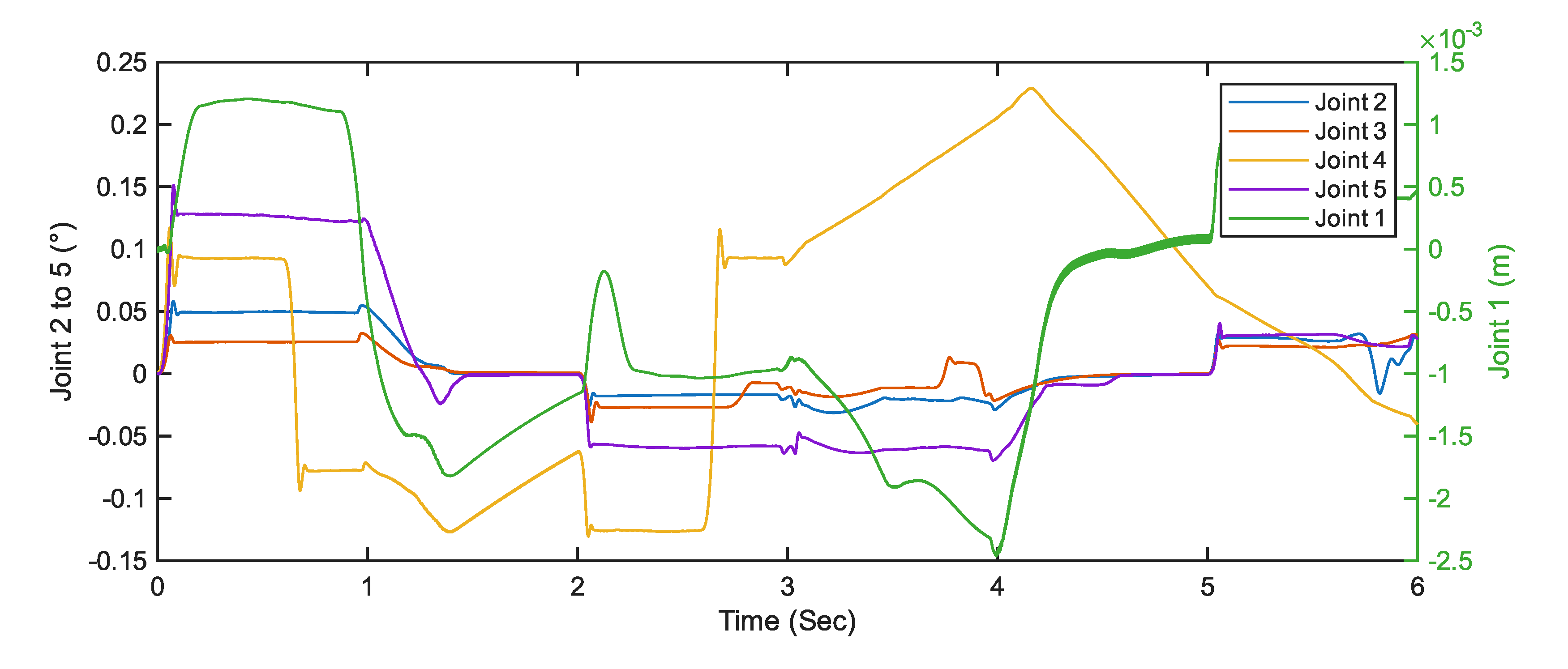
Figure 18 shows excellent tracking fidelity across all five joints under simultaneous activation. The actual joint trajectories closely mirror the reference signals, with minimal phase lag. In Figure 8, tracking errors remain well below 0.06 degrees throughout the simulation. The RMSE is approximately degree.
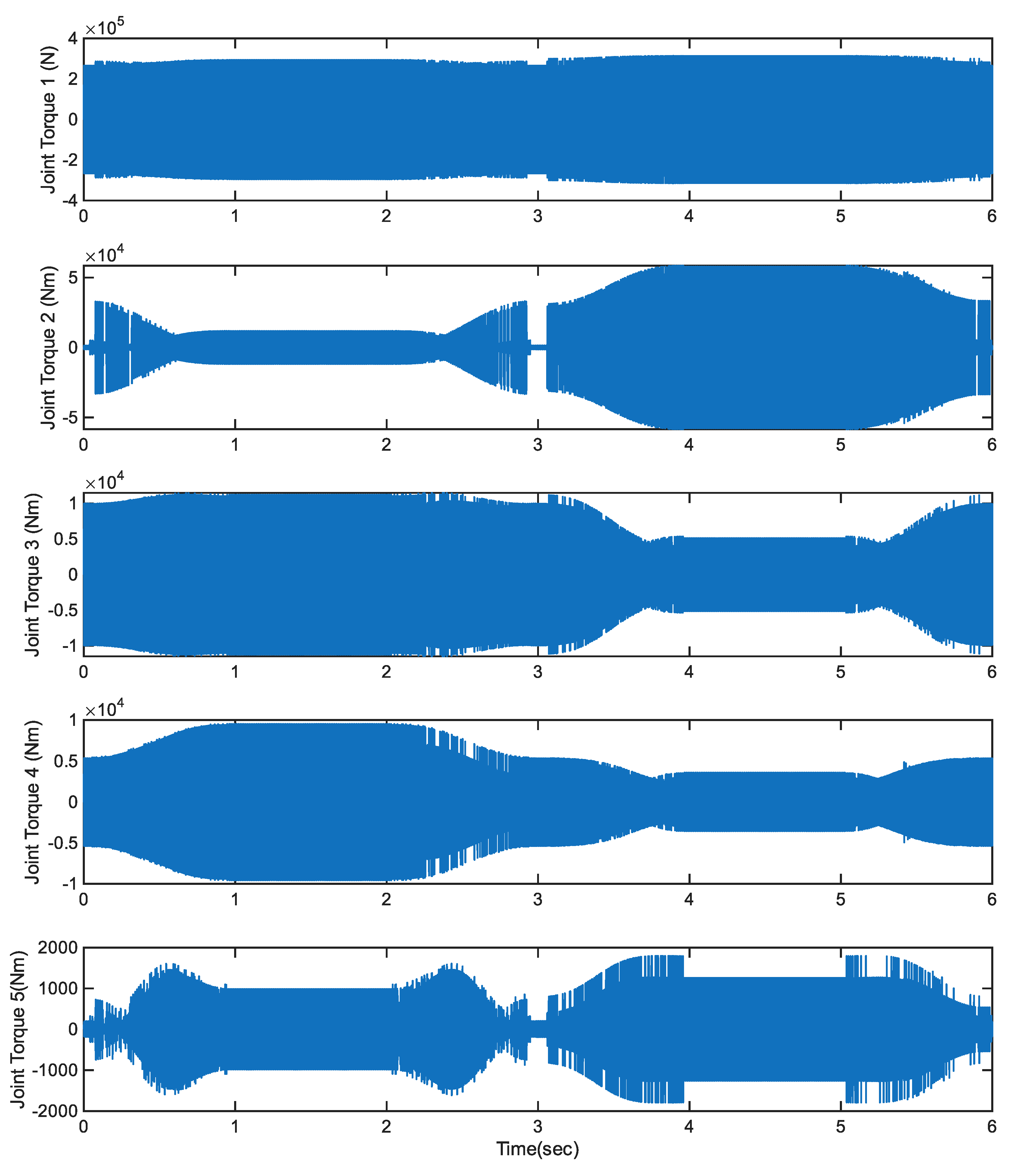
Figure 20.
Joint force and torques.
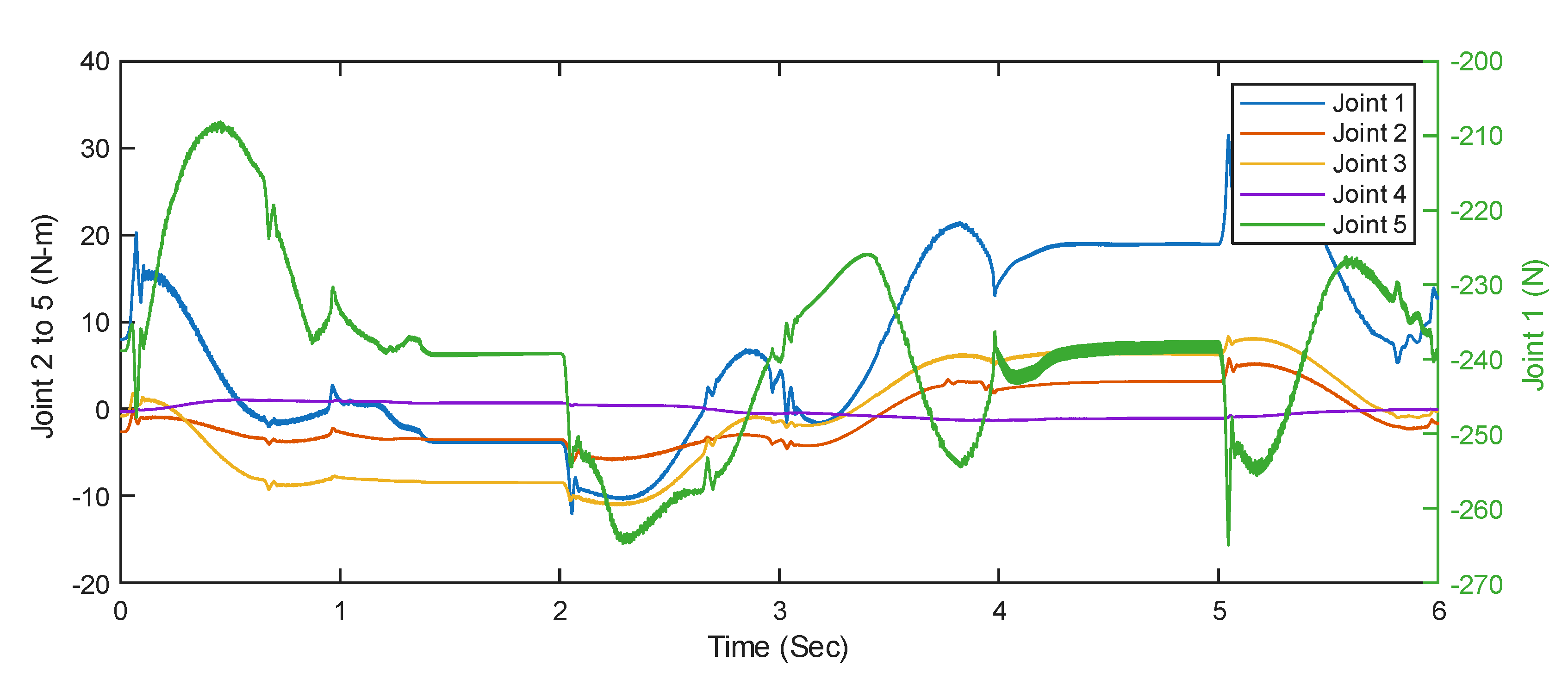
The torque behavior in Figure 20 demonstrates another key benefit of the ASMC: stable, low-magnitude control inputs.
Torque peaks are , and the profiles are significantly smoother than those observed in Figure 14 and Figure 17. This is largely due to the boundary layer design, which replaces the discontinuous switching term with a continuous approximation, thereby eliminating harmful chattering.
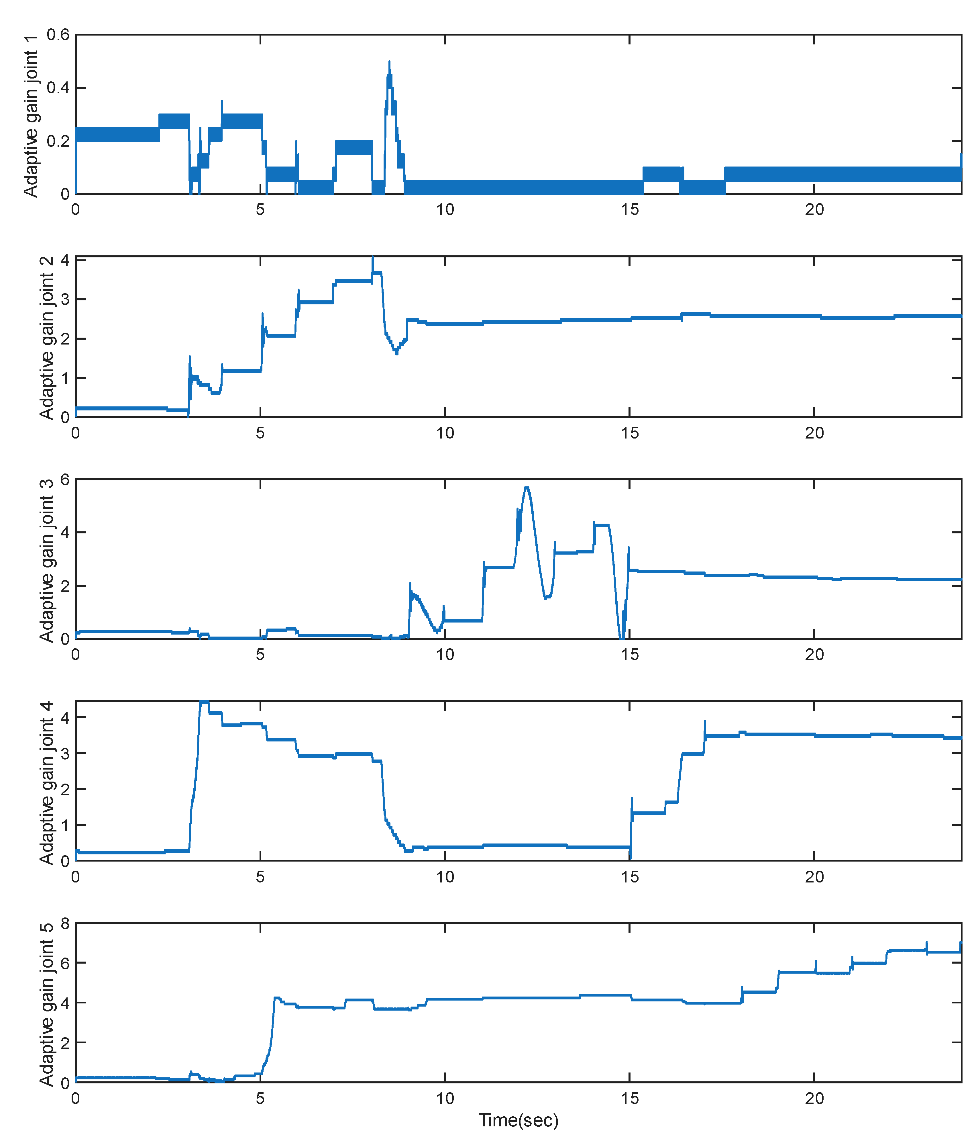
Figure 21.
Adaptive Controller’s gains.
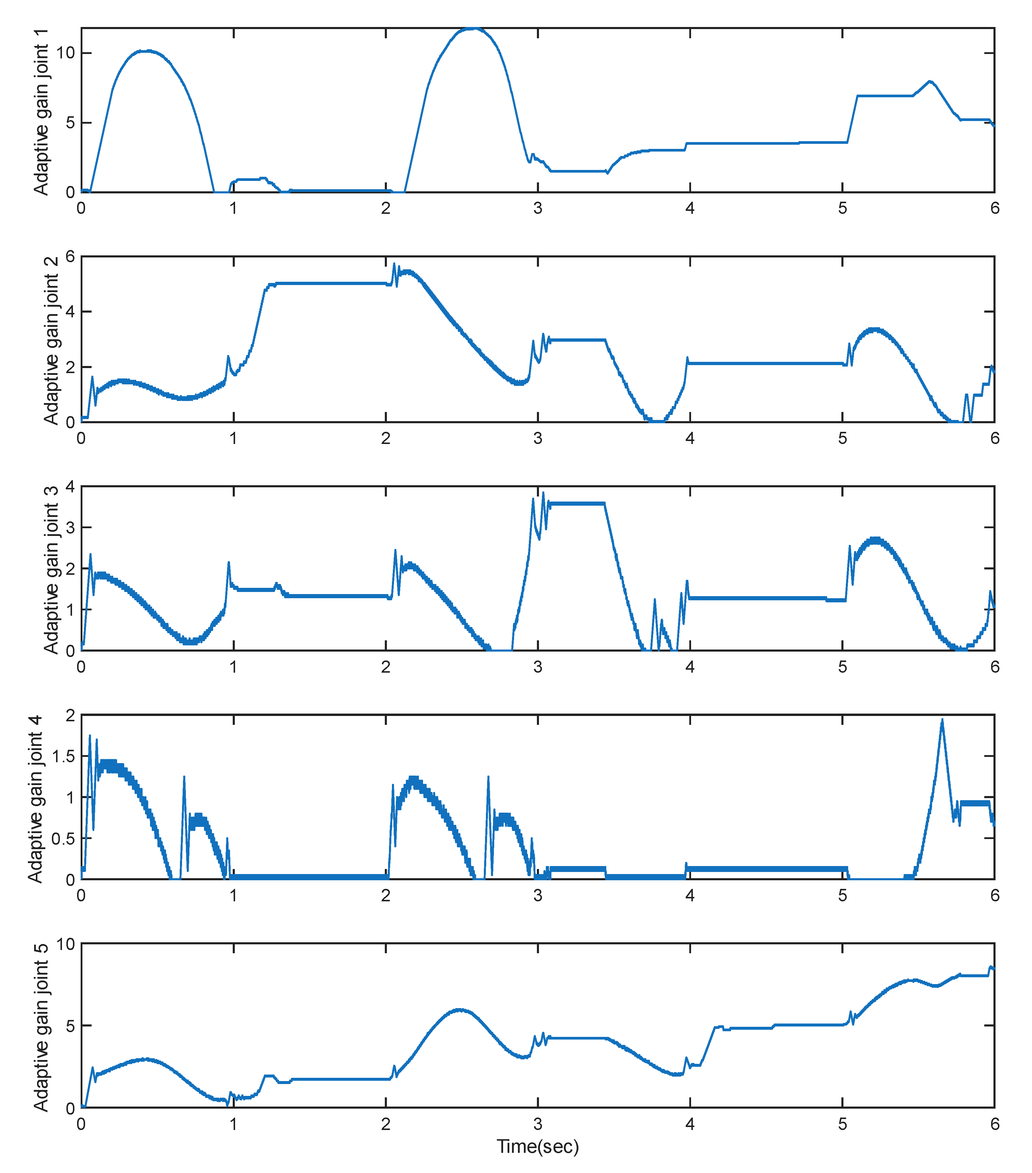
Figure 21 displays the evolution of adaptive gains, which respond dynamically to changes in the sliding surface. These gains automatically increase during rapid deviations and decay when tracking stabilizes, ensuring just enough control effort is applied to maintain robustness. This level of intelligence in control gain modulation enhances both efficiency and long-term mechanical reliability.
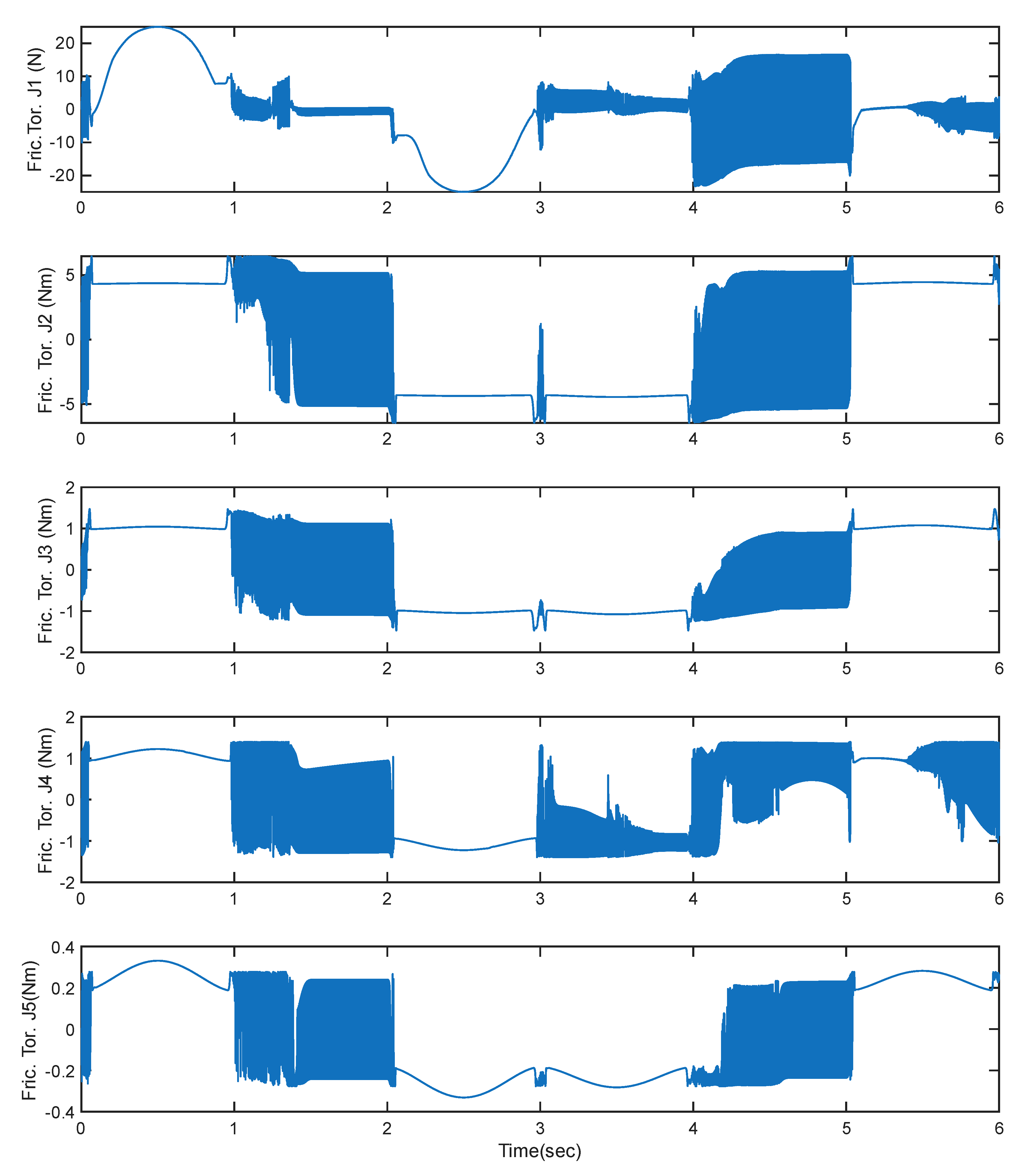
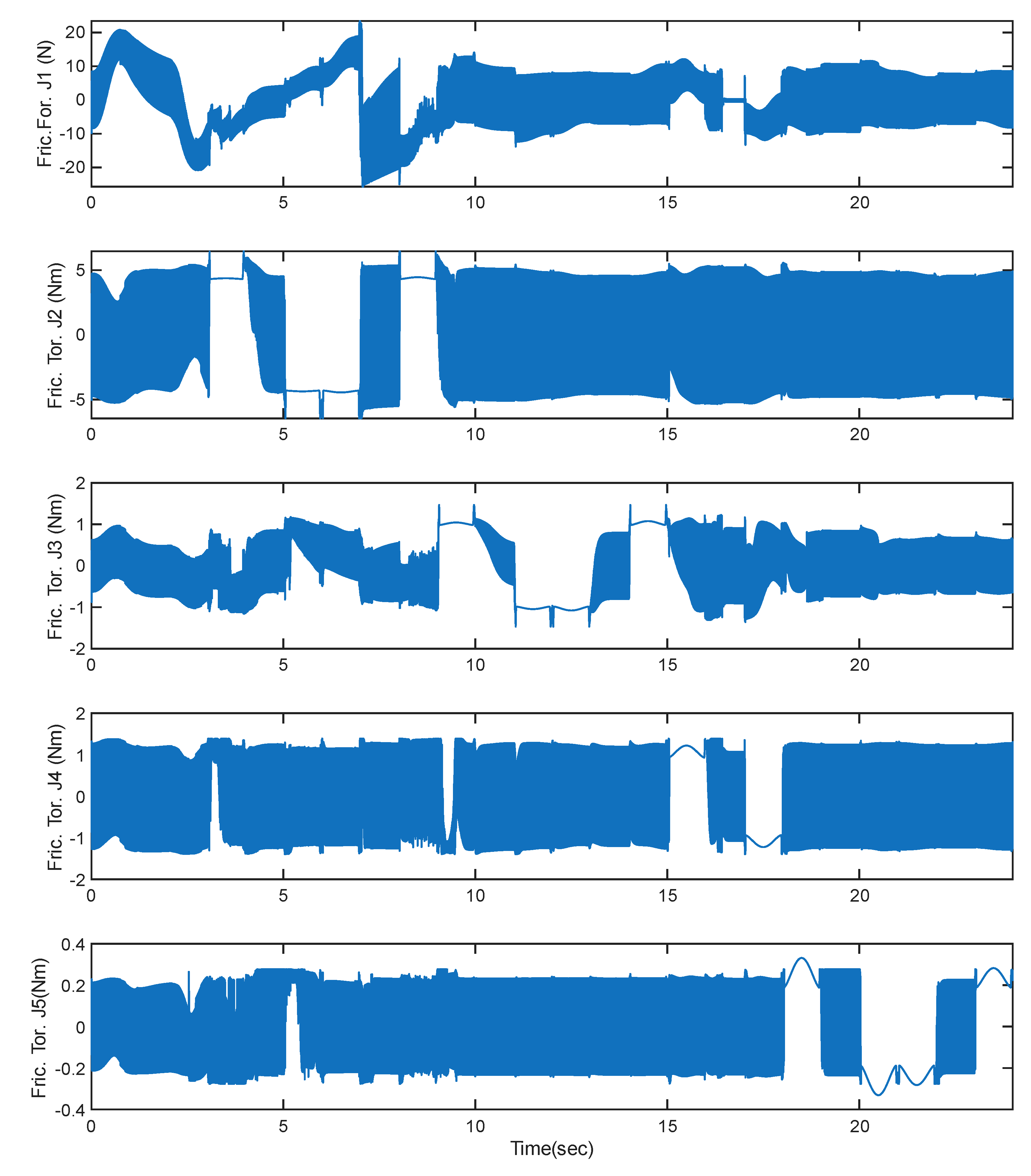
Figure 22 illustrates the frictional forces and torques generated during simultaneous trajectory tracking. The friction force acting on Joint 1 is approximately 22 N, while the friction torques for Joints 2 through 4 are about [6, 1, 1, 0.20] N-m, respectively.
Figure 22.
Joint friction during simultaneous joint movements.
6.4. Adaptive SMC with Chattering Suppressor – Sequential Joint Movements
Figure 23 to Figure 25 examine the same adaptive controller when joints are actuated sequentially. While this setup inherits the limitations of sequential motion in terms of joint coordination, it benefits from the same adaptive and smooth control behavior observed earlier.
Figure 23.
Trajectory Tracking Performance.
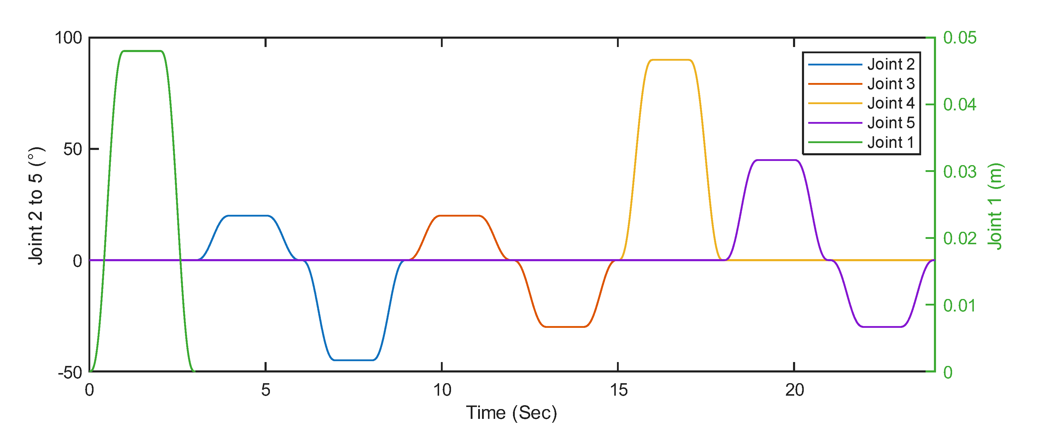
Figure 24.
Trajectory Tracking Errors.
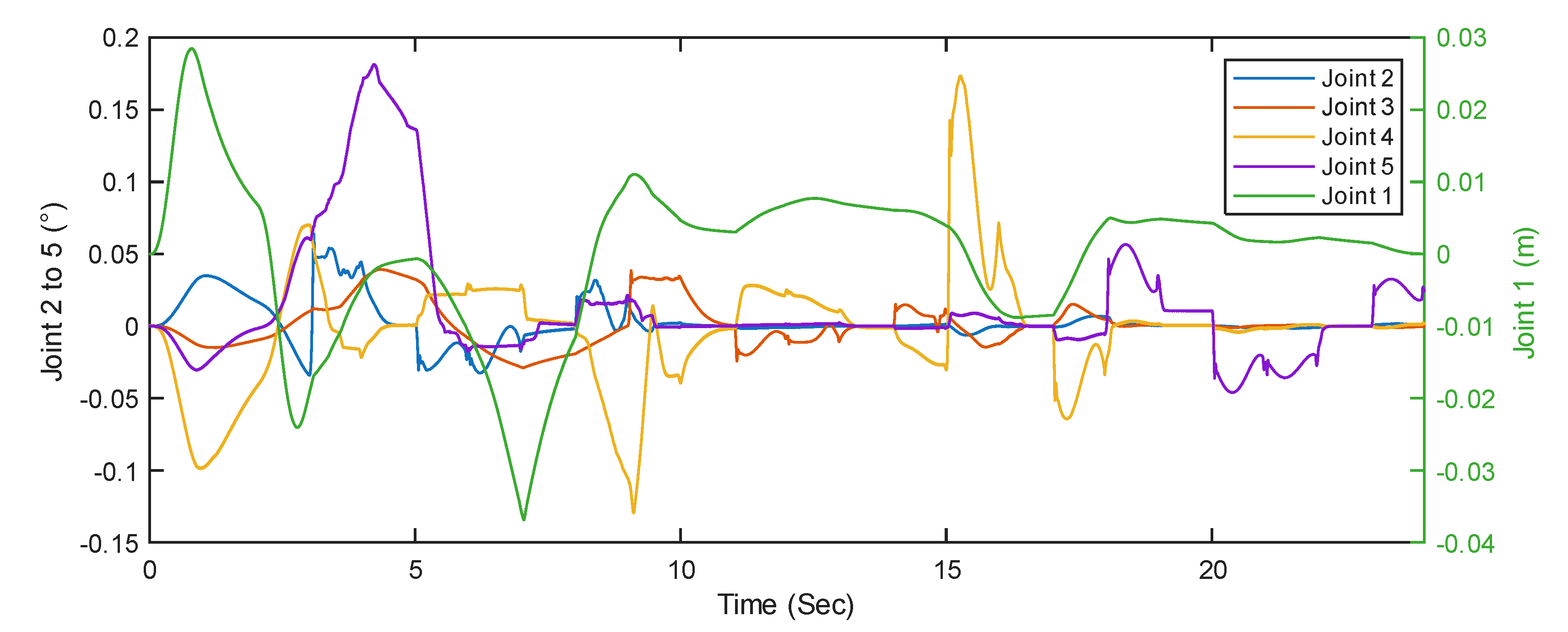
In Figure 24, each joint successfully tracks its target trajectory with minimal overshoot. Tracking errors in Figure 24 are contained under 0.05 degrees, with an average RMSE of 0.02 deg. This level of precision is well-suited for rehabilitation scenarios where isolated joint training must be both safe and accurate. The torque profiles in Figure 25 peak force/torques are around.
Figure 25.
Joint Torque Requirements.
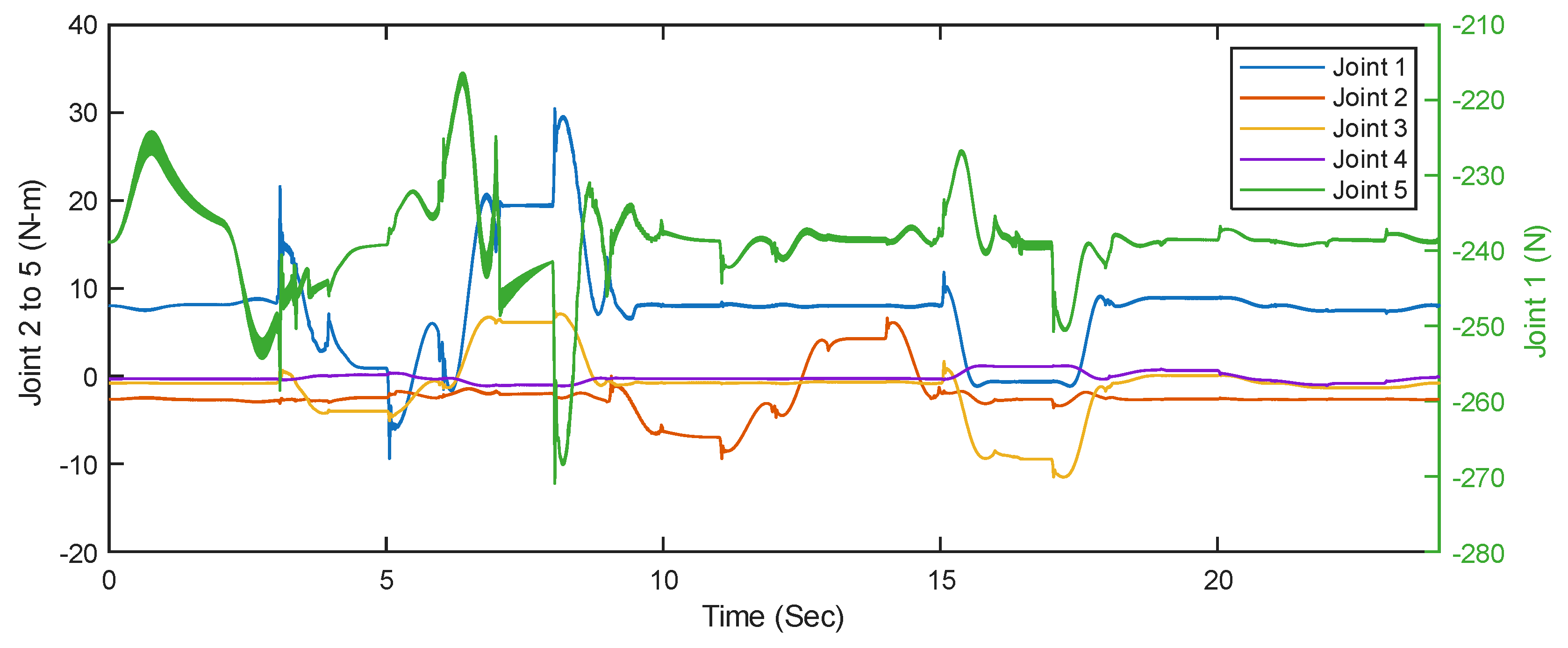
Figure 26.
Adaptive Gains of the developed Sliding Mode Controller.
and remain smooth throughout. As seen in Figure 26, adaptive gain adjustment is gradual and tailored to the demands of each joint's motion. This ensures low control effort during steady-state phases while maintaining responsiveness during dynamic transitions.
This strategy is highly beneficial for early-stage patients who may require isolated joint rehabilitation before progressing to full gait training. It offers both safety and comfort without sacrificing performance.
The simulation results highlight several important insights regarding the control strategies for lower extremity exoskeletons. Adaptive controllers, particularly those enhanced with chattering suppression mechanisms, consistently outperformed others across all key metrics, including trajectory tracking accuracy, torque smoothness, and control efficiency. In contrast, conventional sliding mode control (SMC), despite its robustness and simplicity, demonstrated significant limitations under simultaneous joint actuation, most notably the presence of severe chattering and elevated torque spikes, which could compromise both mechanical integrity and user comfort. While sequential joint activation mitigated dynamic coupling and simplified the control structure, it compromised natural gait coordination, which is essential for realistic and functional rehabilitation. From a clinical perspective, adaptive controllers offer versatility and are well-suited for both early-stage, joint-specific therapies and advanced, full-limb rehabilitation tasks requiring synchronized motion. Furthermore, the proposed adaptive SMC framework is not only scalable and tailored to individual users but also computationally.
Figure 27 illustrates the frictional forces and torques generated during trajectory tracking. The friction force acting on Joint 1 is approximately 22 N, while the friction torques for Joints 2 through 4 are about [5, 1.5, 1, 0.20] Nm, respectively.
Figure 27.
Friction torque induced during sequential trajectory tracking.
7. Discussion and Future Recommendations
This study presented the biomechanical design, dynamic modeling, and control of a 4-degree-of-freedom (DOF) lower extremity exoskeleton robot aimed at rehabilitation applications. The system was designed to replicate essential joint movements of the hip, knee, and ankle, while maintaining anatomical congruency and modular adaptability across different user profiles. The dynamic model, developed using a Lagrangian formulation, captured the nonlinear characteristics of human gait, including inertial, gravitational, and Coriolis forces. A key contribution of this work was the implementation of an adaptive sliding mode controller (SMC) with a boundary layer-based chattering suppressor, which ensured robust trajectory tracking while mitigating the high-frequency oscillations typically associated with traditional SMC.
Sliding mode control is known for its robustness against model uncertainties and external disturbances, making it suitable for complex, nonlinear systems such as wearable exoskeletons. However, the discontinuous nature of the standard sign function leads to chattering, which can cause mechanical wear, actuator heating, and user discomfort. These effects are particularly problematic in physical human-robot interaction where comfort and safety are critical. To address this, the proposed controller introduces a smooth saturation function within a defined boundary layer, effectively attenuating chattering while preserving convergence characteristics. Furthermore, the controller adaptively adjusts the sliding gain in real time based on error magnitude, allowing the system to apply strong corrective actions during large deviations and minimal intervention during convergence, enhancing both safety and energy efficiency.
Simulation results confirmed that the adaptive SMC achieved superior tracking accuracy, reduced torque fluctuations, and improved responsiveness across all joints. The controller maintained high performance during both sequential and simultaneous joint activations, indicating its ability to support isolated joint therapy as well as coordinated gait rehabilitation. These characteristics make it particularly suitable for early-stage recovery where precise control is essential, and for advanced therapy that requires multi-joint coordination.
Despite these promising results, several limitations remain. First, the simulation environment did not incorporate practical non-idealities such as sensor noise, actuator saturation, joint backlash, and soft tissue compliance. Future work must validate the proposed system through hardware-in-the-loop experiments and physical implementation on a wearable exoskeleton platform. Such real-world testing will reveal dynamic interaction forces, misalignment effects, and other user-specific factors not captured in simulation.
Second, the current control strategy lacks integration of physiological signals that reflect user intent. In rehabilitation, encouraging voluntary effort is critical for promoting neuroplasticity and functional recovery. Biosignals such as surface electromyography (sEMG), skin conductance, or inertial measurements can be used to infer motor intent, fatigue, or engagement. Incorporating these inputs into a human-in-the-loop adaptive control framework could enable real-time modulation of assistance levels, aligning robotic support with the user’s physical and cognitive state.
Another opportunity lies in enhancing the controller with data-driven learning algorithms. Reinforcement learning (RL), adaptive neural networks, or Gaussian process models could be used to continuously refine control parameters based on performance feedback. Such learning-enabled systems can autonomously adapt to individual recovery trajectories, optimize assistance levels, and reduce the need for manual gain tuning.
From a mechanical perspective, extending the system’s degrees of freedom, particularly by adding pelvis, toe, or transverse-plane joints would enable more natural gait patterns and allow rehabilitation on uneven terrains. Incorporating lightweight actuators, compliant materials, and ergonomic braces would improve wearability, particularly for long-term use in home or community settings. Modular components could allow clinicians to customize the exoskeleton based on user anthropometrics and therapy needs.
In addition, the development of an intelligent human-machine interface is recommended. A virtual avatar or voice-guided assistant can provide real-time feedback, motivational coaching, and adaptive instruction, increasing therapy adherence and user satisfaction. Coupling this with remote monitoring systems would enable therapists to track progress, adjust therapy parameters, and provide support without requiring in-person visits, especially beneficial for patients in rural or underserved regions.
Finally, the success of the system should be evaluated using a comprehensive protocol that includes both objective and subjective metrics. In addition to kinematic and dynamic tracking performance, outcomes such as muscle activation (via EMG), gait symmetry, range of motion, and energy expenditure should be assessed. Subjective evaluations should include user comfort, cognitive load, emotional engagement, and perceived benefit. Longitudinal studies will be essential to determine the impact of the exoskeleton on functional independence and quality of life.
In conclusion, this work advances the state-of-the-art in exoskeleton control by addressing a critical limitation of sliding mode control and proposing an adaptive, chattering-free solution suitable for rehabilitation. The proposed controller exhibits robust performance under diverse motion tasks and is scalable to broader rehabilitation scenarios. Future work should focus on integrating physiological feedback, implementing real-time experiments, and extending system functionality with intelligent interfaces and learning-based algorithms. These developments will support the creation of an accessible, adaptive, and user-centered rehabilitation platform with the potential to enhance recovery outcomes and democratize access to care.
8. Conclusion
This paper presented the design, dynamic modeling, and control of a 4-degree-of-freedom lower extremity exoskeleton robot developed for rehabilitation applications. The system was designed with anatomically aligned joints and a modular structure to support a wide range of patient anthropometries and rehabilitation needs. A Lagrangian-based dynamic model captured the nonlinear joint behaviors under multi-joint motion, forming the basis for real-time control and simulation.
To ensure accurate and robust joint trajectory tracking, an adaptive sliding mode controller with boundary layer-based chattering suppression was developed and validated through simulation. This controller effectively maintained robustness against modeling uncertainties while significantly reducing chattering, a common limitation in conventional SMC implementations. The adaptive gain mechanism further enhanced controller performance by dynamically adjusting control effort based on real-time error magnitudes. Simulation results demonstrated improved tracking accuracy, smoother torque output, and overall control stability across all joints.
The proposed control strategy supports both isolated joint actuation and coordinated limb movement, making it suitable for various stages of neurorehabilitation, from early passive training to active, task-oriented therapy. The controller's performance, scalability, and safety characteristics position it as a promising solution for wearable, user-specific rehabilitation systems.
Future work will focus on hardware implementation, human-in-the-loop validation, and integration of physiological intent detection using biosignals such as EMG. Additional improvements will include expansion to full-limb rehabilitation, incorporation of learning-based controllers, and development of intelligent user interfaces to enhance patient engagement and adherence.
In summary, the proposed adaptive control framework marks a significant step toward safe, efficient, and personalized exoskeleton-assisted rehabilitation, with strong potential for clinical translation and deployment in home and community settings.
References
- M. Dollar and H. Herr, “Lower extremity exoskeletons and active orthoses: Challenges and state-of-the-art,” IEEE Trans. Robot., vol. 24, no. 1, pp. 144–158, Feb. 2008. [CrossRef]
- D. R. Louie and J. J. Eng, “Powered robotic exoskeletons in post-stroke rehabilitation of gait: A scoping review,” J. Neuroeng. Rehabil., vol. 13, no. 1, pp. 1–10, 2016. [CrossRef]
- M. R. Tucker et al., “Control strategies for active lower extremity prosthetics and orthotics: A review,” J. Neuroeng. Rehabil., vol. 12, no. 1, pp. 1–30, 2015. [CrossRef]
- Plaza, M. Hernandez, G. Puyuelo, E. Garces, and E. Garcia, “Lower-limb medical and rehabilitation exoskeletons: A review of the current designs,” IEEE Rev. Biomed. Eng., vol. 16, pp. 278–291, 2023. [CrossRef]
- W. Huo, S. W. Huo, S. Mohammed, J. C. Moreno, and Y. Amirat, “Lower limb wearable robots for assistance and rehabilitation: A state of the art,” IEEE Syst. J., vol. 10, no. 3, pp. 1068–1081, Sep. 2016. [CrossRef]
- R. Baud, A. R. R. Baud, A. R. Manzoori, A. Ijspeert, and M. Bouri, “Review of control strategies for lower-limb exoskeletons to assist gait,” J. Neuroeng. Rehabil., vol. 18, no. 1, pp. 1–34, 2021. [CrossRef]
- J. L. Pons, Wearable Robots: Biomechatronic Exoskeletons. Hoboken, NJ, USA: Wiley, 2008. [CrossRef]
- V. I. Utkin, “Sliding mode control design principles and applications to electric drives,” IEEE Trans. Ind. Electron., vol. 40, no. 1, pp. 23–36, Feb. 1993. [CrossRef]
- S. K. Hasan and A. K. Dhingra, “Development of a sliding mode controller with chattering suppressor for human lower extremity exoskeleton robot,” Results Control Optim., vol. 7, Art. no. 100123, 2022. [CrossRef]
- V. Firouzi, A. V. Firouzi, A. Seyfarth, S. Song, O. von Stryk, and M. A. Sharbafi, “Biomechanical models in the lower-limb exoskeletons development: A review,” J. Neuroeng. Rehabil., vol. 22, no. 1, pp. 1–20, 2025. [CrossRef]
- H. Wang, H. H. Wang, H. Shen, Y. Han, W. Zhou, and J. Wang, “Effect of robot-assisted training for lower limb rehabilitation on lower limb function in stroke patients: A systematic review and meta-analysis,” Front. Hum. Neurosci., vol. 19, Art. no. 1549379, 2025. [CrossRef]
- M. M. Hu et al., “Efficacy of robot-assisted gait training on lower extremity function in subacute stroke patients: A systematic review and meta-analysis,” J. Neuroeng. Rehabil., vol. 21, no. 1, pp. 1–15, 2024. [CrossRef]
- J. Yang et al., “Effect of robotic exoskeleton training on lower limb function, activity and participation in stroke patients: A systematic review and meta-analysis of randomized controlled trials,” Front. Neurol., vol. 15, Art. no. 1453781, 2024. [CrossRef]
- M. Daliri et al., “Powered single hip joint exoskeletons for gait rehabilitation: A systematic review and meta-analysis,” BMC Musculoskelet. Disord., vol. 25, no. 1, pp. 1–15, 2024. [CrossRef]
- Y. Zhou, “User experience of lower extremity exoskeletons and its improvement methodologies: A narrative review,” Proc. Inst. Mech. Eng., Part H: J. Eng. Med., vol. 238, no. 9, pp. 1052–1068, 2024. [CrossRef]
- J. de Miguel-Fernández, J. J. de Miguel-Fernández, J. Lobo-Prat, E. Prinsen, J. M. Font-Llagunes, and L. Marchal-Crespo, “Control strategies used in lower limb exoskeletons for gait rehabilitation after brain injury: A systematic review and analysis of clinical effectiveness,” J. Neuroeng. Rehabil., vol. 20, no. 1, pp. 1–28, 2023. [CrossRef]
- X. R. G. Leow, S. L. A. X. R. G. Leow, S. L. A. Ng, and Y. Lau, “Overground robotic exoskeleton training for patients with stroke on walking-related outcomes: A systematic review and meta-analysis of randomized controlled trials,” Arch. Phys. Med. Rehabil., vol. 104, no. 9, pp. 1698–1710, 2023. [CrossRef]
- G. Colombo, M. G. Colombo, M. Joerg, R. Schreier, and V. Dietz, “Treadmill training of paraplegic patients using a robotic orthosis,” J. Rehabil. Res. Dev., vol. 37, no. 6, pp. 693–700, 2000.
- M. Bernhardt, G. M. Bernhardt, G. Colombo, and R. Riener, “Hybrid force-position control yields cooperative behaviour of the rehabilitation robot LOKOMAT,” in Proc. 9th Int. Conf. Rehabil. Robot. (ICORR), Chicago, IL, USA, Jun. 2005, pp. 536–539.
- R. Riener et al., “Patient-cooperative strategies for robot-aided treadmill training: First experimental results,” IEEE Trans. Neural Syst. Rehabil. Eng., vol. 13, no. 3, pp. 380–394, Sep. 2005. [CrossRef]
- J. K. Burgess, G. C. J. K. Burgess, G. C. Weibel, and D. A. Brown, “Overground walking speed changes when subjected to body weight support conditions for nonimpaired and post stroke individuals,” J. Neuroeng. Rehabil., vol. 7, no. 1, Art. no. 6, Feb. 2010. [CrossRef]
- M. Peshkin et al., “KineAssist: A robotic overground gait and balance training device,” in Proc. 9th Int. Conf. Rehabil. Robot. (ICORR), Chicago, IL, USA, Jun. 2005, pp. 241–246.
- J. F. Veneman, R. J. F. Veneman, R. Ekkelenkamp, R. Kruidhof, F. C. T. van der Helm, and H. van der Kooij, “Design of a series elastic- and Bowden-cable-based actuation system for use as torque-actuator in exoskeleton-type training,” in Proc. IEEE 9th Int. Conf. Rehabil. Robot. (ICORR), Chicago, IL, USA, Jun. 2005, pp. 496–499. [CrossRef]
- J. F. Veneman et al., “Design and evaluation of the LOPES exoskeleton robot for interactive gait rehabilitation,” IEEE Trans. Neural Syst. Rehabil. Eng., vol. 15, no. 3, pp. 379–386, Sep. 2007. [CrossRef]
- S. M. M. D. Rossi et al., “Sensing pressure distribution on a lower-limb exoskeleton physical human–machine interface,” Sensors, vol. 11, no. 1, pp. 207–227, 2011. [CrossRef]
- S. K. Banala, S. K. S. K. Banala, S. K. Agrawal, and J. P. Scholz, “Active Leg Exoskeleton (ALEX) for gait rehabilitation of motor-impaired patients,” in Proc. IEEE 10th Int. Conf. Rehabil. Robot. (ICORR), 2007, pp. 401–407. [CrossRef]
- Díaz, J. J. Gil, and E. Sánchez, “Lower-limb robotic rehabilitation: Literature review and challenges,” J. Robot., vol. 2011, Art. no. 759764, 2011. [CrossRef]
- D. Zanotto, P. D. Zanotto, P. Stegall, and S. K. Agrawal, “ALEX III: A novel robotic platform with 12 DOFs for human gait training,” in Proc. IEEE Int. Conf. Robot. Autom. (ICRA), 2013, pp. 3914–3919. [CrossRef]
- K. Kong, M. K. Kong, M. Tomizuka, H. Moon, B. Hwang, and D. Jeon, “Mechanical design and impedance compensation of SUBAR (Sogang University’s Biomedical Assist Robot),” in Proc. IEEE/ASME Int. Conf. Adv. Intell. Mechatron. (AIM), 2008, pp. 377–382. [CrossRef]
- K. Kong and D. Jeon, “Design and control of an exoskeleton for the elderly and patients,” IEEE/ASME Trans. Mechatronics, vol. 11, no. 4, pp. 428–432, Aug. 2006. [CrossRef]
- H. Munawar, M. H. Munawar, M. Yalcin, and V. Patoglu, “AssistOn-Gait: An overground gait trainer with an active pelvis-hip exoskeleton,” in Proc. IEEE Int. Conf. Rehabil. Robot. (ICORR), 2015, pp. 594–599. [CrossRef]
- T. Ikehara et al., “Development of closed-fitting-type walking assistance device for legs and evaluation of muscle activity,” in Proc. IEEE Int. Conf. Rehabil. Robot. (ICORR), 2011, pp. 1–7. [CrossRef]
- S. Lee and Y. Sankai, “Power assist control for walking aid with HAL-3 based on EMG and impedance adjustment around knee joint,” in Proc. IEEE/RSJ Int. Conf. Intell. Robots Syst. (IROS), vol. 2, 2002, pp. 1499–1504. [CrossRef]
- H. Kawamoto and Y. Sankai, “Power assist method based on phase sequence driven by interaction between human and robot suit,” in Proc. IEEE Int. Workshop Robot Human Interact. Commun. (ROMAN), 2004, pp. 491–496. [CrossRef]
- Y. Sankai, “HAL: Hybrid assistive limb based on cybernics,” in Springer Tracts Adv. Robot., vol. 66, pp. 25–34, 2010. [CrossRef]
- E. Guizzo and H. Goldstein, “The rise of the body bots,” IEEE Spectr., vol. 42, no. 10, pp. 50–56, Oct. 2005. [CrossRef]
- T. Teramae, T. T. Teramae, T. Noda, and J. Morimoto, “Optimal control approach for pneumatic artificial muscle with using pressure-force conversion model,” in Proc. IEEE Int. Conf. Robot. Autom. (ICRA), 2014, pp. 4792–4797. [CrossRef]
- Chen, C. H. Zhong, X. Zhao, H. Ma, L. Qin, and W. H. Liao, “Reference joint trajectories generation of CUHK-EXO exoskeleton for system balance in walking assistance,” IEEE Access, vol. 7, pp. 33809–33821, 2019. [CrossRef]
- R. J. Farris, H. A. R. J. Farris, H. A. Quintero, and M. Goldfarb, “Performance evaluation of a lower limb exoskeleton for stair ascent and descent with paraplegia,” in Proc. Annu. Int. Conf. IEEE Eng. Med. Biol. Soc. (EMBC), 2012, pp. 1908–1911. [CrossRef]
- P. D. Neuhaus, J. H. P. D. Neuhaus, J. H. Noorden, T. J. Craig, T. Torres, J. Kirschbaum, and J. E. Pratt, “Design and evaluation of Mina: A robotic orthosis for paraplegics,” in Proc. IEEE Int. Conf. Rehabil. Robot. (ICORR), 2011, pp. 1–8. [CrossRef]
- Feng, Y. Yong, Y. Ge, and F. Yu, “WPAL for human power assist during walking using dynamic equation,” in Proc. IEEE Int. Conf. Mechatronics Autom. (ICMA), 2009, pp. 1039–1043. [CrossRef]
- L. Wang, S. L. Wang, S. Wang, E. H. F. van Asseldonk, and H. van der Kooij, “Actively controlled lateral gait assistance in a lower limb exoskeleton,” in Proc. IEEE/RSJ Int. Conf. Intell. Robots Syst. (IROS), 2013, pp. 965–970. [CrossRef]
- Y. Mori, J. Y. Mori, J. Okada, and K. Takayama, “Development of a standing style transfer system ‘ABLE’ for disabled lower limbs,” IEEE/ASME Trans. Mechatronics, vol. 11, no. 4, pp. 372–380, Aug. 2006. [CrossRef]
- M. V. Araújo, P. J. M. V. Araújo, P. J. Alsina, V. C. C. Roza, and N. B. Melo, “Powered orthosis Ortholeg: Design and development,” IEEE Lat. Am. Trans., vol. 13, no. 1, pp. 90–95, Jan. 2015. [CrossRef]
- M. Gloger, P. J. M. Gloger, P. J. Alsina, and N. B. Melo, “Ortholeg 2.0 – A new design for a lower limb active orthosis,” in Proc. Int. Symp. Micro-NanoMechatronics Human Sci. (MHS), 2015, pp. 1–6. [CrossRef]
- U. Umar, H. S. U. Umar, H. S. Minhas, N. Naseer, H. Nazeer, S. Iqbal, and M. N. Ahmed, “Design and simulation of lower-limb exoskeleton to assist paraplegic people in walking,” in Proc. Int. Conf. Control, Decision Inf. Technol. (CoDIT), 2022, pp. 855–860. [CrossRef]
- T. Nakamura and K. Kosuge, “Model-based walking support system with wearable walking helper,” in Proc. IEEE Int. Workshop Robot Human Interact. Commun. (ROMAN), 2003, pp. 61–66. [CrossRef]
- T. Nakamura, K. T. Nakamura, K. Saito, Z. D. Wang, and K. Kosuge, “Realizing model-based wearable antigravity muscles support with dynamics terms,” in Proc. IEEE/RSJ Int. Conf. Intell. Robots Syst. (IROS), 2005, pp. 2694–2699. [CrossRef]
- T. Nakamura, K. T. Nakamura, K. Saito, and K. Kosuge, “Control of wearable walking support system based on human-model and GRF,” in Proc. IEEE Int. Conf. Robot. Autom. (ICRA), 2005, pp. 4394–4399. [CrossRef]
- S. Jezernik, G. S. Jezernik, G. Colombo, T. Keller, H. Frueh, and M. Morari, “Robotic orthosis Lokomat: A rehabilitation and research tool,” Neuromodulation: Technol. Neural Interface, vol. 6, no. 2, pp. 108–115, 2003. [CrossRef]
- M. Bernhardt, M. M. Bernhardt, M. Frey, G. Colombo, and R. Riener, “Hybrid force-position control yields cooperative behaviour of the rehabilitation robot Lokomat,” in Proc. IEEE 9th Int. Conf. Rehabil. Robot. (ICORR), 2005, pp. 536–539. [CrossRef]
- R. Ekkelenkamp, J. R. Ekkelenkamp, J. Veneman, and H. van der Kooij, “LOPES: Selective control of gait functions during the gait rehabilitation of CVA patients,” in Proc. IEEE 9th Int. Conf. Rehabil. Robot. (ICORR), Chicago, IL, USA, 2005, pp. 361–364.
- K. N. Winfree, P. K. N. Winfree, P. Stegall, and S. K. Agrawal, “Design of a minimally constraining, passively supported gait training exoskeleton: ALEX II,” in Proc. IEEE Int. Conf. Rehabil. Robot. (ICORR), 2011, pp. 1–6. [CrossRef]
- H. Kawamoto, T. H. Kawamoto, T. Hayashi, T. Sakurai, K. Eguchi, and Y. Sankai, “Development of single leg version of HAL for hemiplegia,” in Proc. 31st Annu. Int. Conf. IEEE Eng. Med. Biol. Soc. (EMBC), 2009, pp. 5038–5043. [CrossRef]
- H. Kawamoto and Y. Sankai, “Power assist method based on phase sequence driven by interaction between human and robot suit,” in Proc. IEEE Int. Workshop Robot Human Interact. Commun. (ROMAN), 2004, pp. 491–496. [CrossRef]
- S. Lee and Y. Sankai, “Power assist control for walking aid with HAL-3 based on EMG and impedance adjustment around knee joint,” in Proc. IEEE/RSJ Int. Conf. Intell. Robots Syst. (IROS), vol. 2, 2002, pp. 1499–1504. [CrossRef]
- R. J. Farris, H. A. Quintero, S. A. Murray, K. H. Ha, C. Hartigan, and M. Goldfarb, “A preliminary assessment of legged mobility provided by a lower limb exoskeleton for persons with paraplegia,” IEEE Trans. Neural Syst. Rehabil. Eng., vol. 22, no. 3, pp. 482–490, May 2014. [CrossRef]
- K. Raj, P. D. K. Raj, P. D. Neuhaus, A. M. Moucheboeuf, J. H. Noorden, and D. Lecoutre, “V Mina: A sensorimotor robotic orthosis for mobility assistance,” J. Robot., vol. 2011, Art. no. 284352, 2011. [CrossRef]
- T. Teramae, T. T. Teramae, T. Noda, and J. Morimoto, “Optimal control approach for pneumatic artificial muscle with using pressure-force conversion model,” in Proc. IEEE Int. Conf. Robot. Autom. (ICRA), 2014, pp. 4792–4797. [CrossRef]
- M. V. Araújo, P. J. M. V. Araújo, P. J. Alsina, V. C. C. Roza, and N. B. Melo, “Powered orthosis Ortholeg: Design and development,” IEEE Lat. Am. Trans., vol. 13, no. 1, pp. 90–95, Jan. 2015. [CrossRef]
- M. Gloger, P. J. M. Gloger, P. J. Alsina, and N. B. Melo, “Ortholeg 2.0 – A new design for a lower limb active orthosis,” in Proc. Int. Symp. Micro-NanoMechatronics Human Sci. (MHS), 2015, pp. 1–7. [CrossRef]
- T. Nakamura and K. Kosuge, “Model-based walking support system with wearable walking helper,” in Proc. IEEE Int. Workshop Robot Human Interact. Commun. (ROMAN), 2003, pp. 61–66. [CrossRef]
- S. K. Hasan and A. K. Dhingra, “Performance verification of different control schemes in human lower extremity rehabilitation robot,” Results Control Optim., vol. 4, Art. no. 100028, 2021. [CrossRef]
- Brahmi, M. Driscoll, I. K. El Bojairami, M. Saad, and A. Brahmi, “Novel adaptive impedance control for exoskeleton robot for rehabilitation using a nonlinear time-delay disturbance observer,” ISA Trans., vol. 108, pp. 381–392, 2021. [CrossRef]
- Topini, W. Sansom, N. Secciani, L. Bartalucci, A. Ridolfi, and B. Allotta, “Variable admittance control of a hand exoskeleton for virtual reality-based rehabilitation tasks,” Front. Neurorobot., vol. 15, Art. no. 789743, 2022. [CrossRef]
- S. K. Hasan and A. K. Dhingra, “Development of a sliding mode controller with chattering suppressor for human lower extremity exoskeleton robot,” Results Control Optim., vol. 7, Art. no. 100123, 2022. [CrossRef]
- S. K. Hasan and A. K. Dhingra, “An adaptive controller for human lower extremity exoskeleton robot,” Microsyst. Technol., vol. 27, no. 7, pp. 2829–2846, Jul. 2021. [CrossRef]
- Y. J. Huang, T. C. Y. J. Huang, T. C. Kuo, and S. H. Chang, “Adaptive sliding-mode control for nonlinear systems with uncertain parameters,” IEEE Trans. Syst., Man, Cybern., Part B (Cybern.), vol. 38, no. 2, pp. 534–539, Apr. 2008. [CrossRef]
- M. Van, “Higher-order terminal sliding mode controller for fault accommodation of Lipschitz second-order nonlinear systems using fuzzy neural network,” Appl. Soft Comput., vol. 104, Art. no. 107186, May 2021. [CrossRef]
- S. Luo, G. S. Luo, G. Androwis, S. Adamovich, H. Su, E. Nunez, and X. Zhou, “Reinforcement learning and control of a lower extremity exoskeleton for squat assistance,” Front. Robot. AI, vol. 8, Art. no. 702845, Aug. 2021. [CrossRef]
- X. Bu, “Prescribed performance control approaches, applications and challenges: A comprehensive survey,” Asian J. Control, vol. 25, no. 1, pp. 241–261, Jan. 2023. [CrossRef]
- Y. Pan, X. Y. Pan, X. Li, H. Wang, and H. Yu, “Continuous sliding mode control of compliant robot arms: A singularly perturbed approach,” Mechatronics, vol. 52, pp. 127–134, Jun. 2018. [CrossRef]
- Kaplanoglu and, G. Akgun, “Data-driven predictive control of exoskeleton for hand rehabilitation with subspace identification,” Sensors, vol. 22, no. 19, Art. no. 7645, Oct. 2022. [CrossRef]
- G. G. Peña, L. J. G. G. Peña, L. J. Consoni, W. M. dos Santos, and A. A. G. Siqueira, “Feasibility of an optimal EMG-driven adaptive impedance control applied to an active knee orthosis,” Robot. Auton. Syst., vol. 112, pp. 98–108, Feb. 2019. [CrossRef]
- “Space requirements of the seated operator. Geometrical, kinematic, and mechanical aspects of the body with special reference to the limbs,” Contrails, Illinois Institute of Technology. [Online]. Available: https://contrails.library.iit.edu/item/154630. [Accessed: May 26, 2025].
- R. M. Andrade and P. Bonato, “The role played by mass, friction, and inertia on the driving torques of lower-limb gait training exoskeletons,” IEEE Trans. Med. Robot. Bionics, vol. 3, no. 1, pp. 125–136, Feb. 2021. [CrossRef]
- S. Liu and G. S. Chen, Dynamics and Control of Robotic Manipulators with Contact and Friction. Hoboken, NJ, USA: Wiley, 2018. [CrossRef]
- Pennestrì, V. Rossi, P. Salvini, and P. P. Valentini, “Review and comparison of dry friction force models,” Nonlinear Dyn., vol. 83, pp. 1785–1801, 2016. [CrossRef]
- “Rotational friction – Friction in contact between rotating bodies – MATLAB,” MathWorks. [Online]. Available: https://www.mathworks.com/help/simscape/ref/rotationalfriction.html. [Accessed: Aug. 18, 2025].
- J. L. Ha, R. F. J. L. Ha, R. F. Fung, C. F. Han, and J. R. Chang, “Effects of frictional models on the dynamic response of the impact drive mechanism,” J. Vib. Acoust., vol. 128, no. 1, pp. 88–96, Feb. 2006. [CrossRef]
Figure 10.
Friction model combining Coulomb, viscous and Stribeck effects.
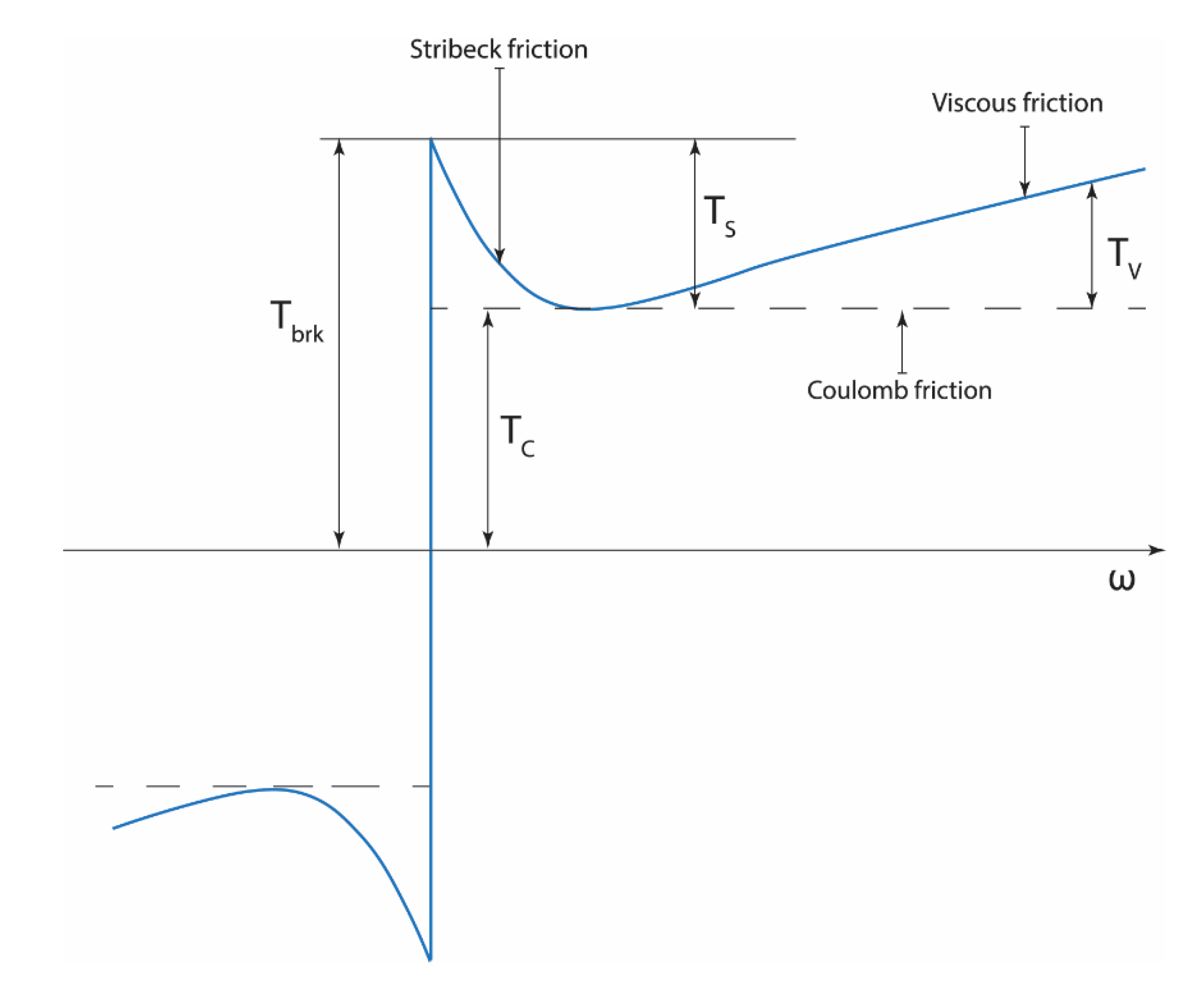
Table 1.
comparison among various human lower extremity exoskeleton robots.
| System Type | Key Features | Control Strategy | Actuation | Use Case |
|---|---|---|---|---|
| Lokomat | Treadmill, harness | Force-position | Motorized (hip, knee) | Stroke, SCI [18,50,51] |
| LOPES | Pelvic DOF, impedance | Impedance w/ SEA | Bowden cable | Post-stroke gait [24,25,52] |
| ALEX Series | Multigen upgrades | Force-field + Feedback | Linear actuators | Gait research [26,27,28,53] |
| HAL | Active/passive, sEMG | Intention-based | Harmonic drives | Rehabilitation [35,36,54,55,56] |
| Vanderbilt | Multimodal, voice cmd | Trajectory replay | Brushless motors | SCI, stroke [39,57] |
| MINA | Modular, SEA | Prescribed gait | SEA | SCI, training [58] |
| XoR | Hybrid (pneumatic + electric) | Biomechanical estimation | Mixed | Elderly posture [59] |
| WPAL | Compliance control | Dynamic model | Motorized | Paralysis [41] |
| MindWalker | XCoM stability | Recorded gait + commands | SEA | SCI [42] |
| Ortholeg | Eye-controlled | Predefined motion | Motorized | SCI [60,61] |
| WWH | Gravity assist | Torque estimation | Motorized | Elderly, impaired [48,49,62] |
Disclaimer/Publisher’s Note: The statements, opinions and data contained in all publications are solely those of the individual author(s) and contributor(s) and not of MDPI and/or the editor(s). MDPI and/or the editor(s) disclaim responsibility for any injury to people or property resulting from any ideas, methods, instructions or products referred to in the content. |
© 2025 by the authors. Licensee MDPI, Basel, Switzerland. This article is an open access article distributed under the terms and conditions of the Creative Commons Attribution (CC BY) license (http://creativecommons.org/licenses/by/4.0/).
Copyright: This open access article is published under a Creative Commons CC BY 4.0 license, which permit the free download, distribution, and reuse, provided that the author and preprint are cited in any reuse.


