
Submitted:
21 August 2025
Posted:
22 August 2025
You are already at the latest version
Abstract
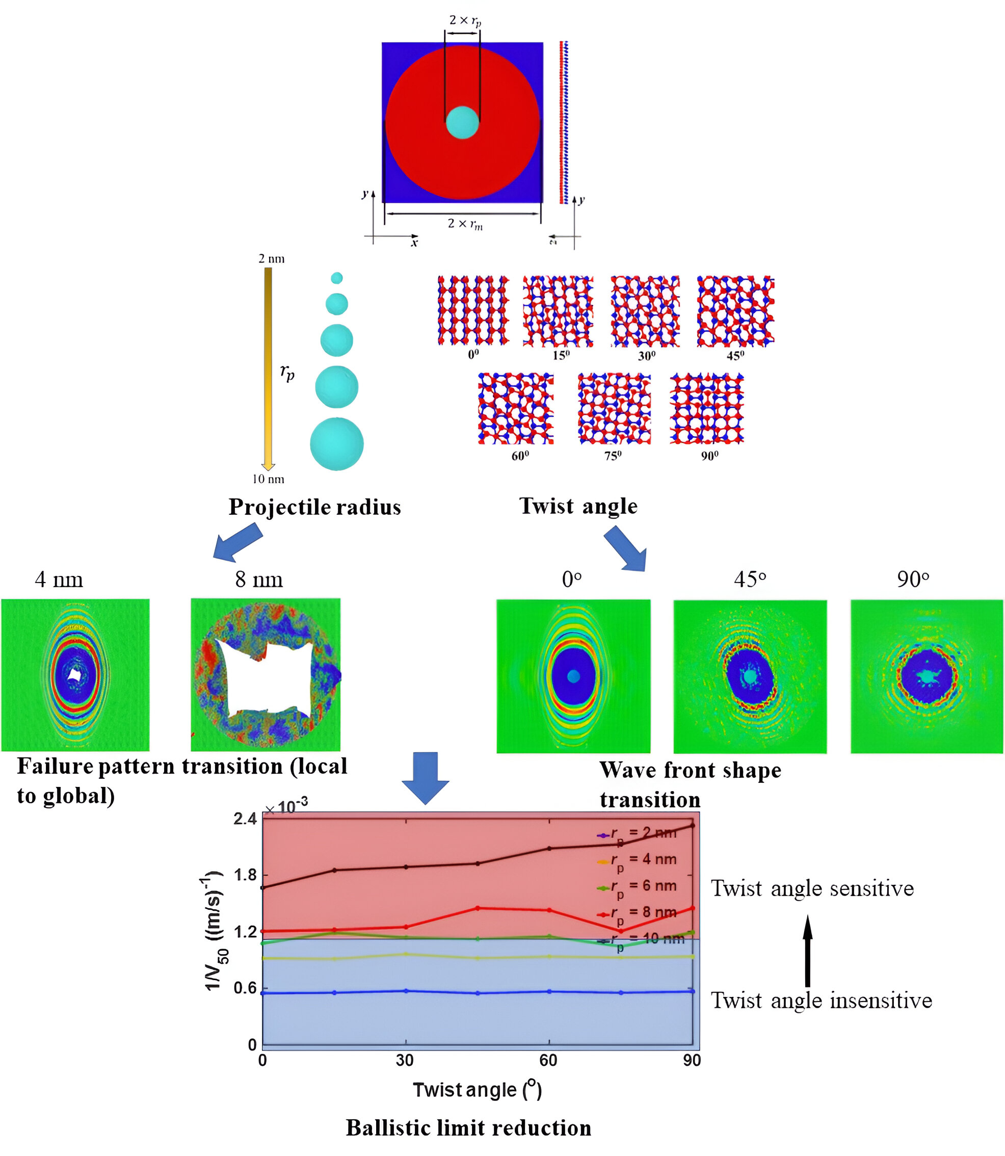
This study employs coarse-grained molecular dynamics simulations to investigate the synergistic coupling between interlayer twist angle (0°–90°) and projectile radius (2–10 nm) on the ballistic impact performance of bilayer phosphorene membranes (radius: 48 nm). For projectiles ≤6 nm, twist angle minimally influences impact forces, velocity attenuation, or ballistic limit velocity, as failure remains localized near the impact site. However, cone wavefront morphology evolves significantly with twist—progressing from elliptical (axial ratio 1.44 at 0°) to circular (ratio 1.0 at 90°) while rotating counterclockwise. Crucially, for projectiles ≥8 nm, twist angle critically modulates mechanical response: maximum impact force fluctuates negligibly below 60° but surges by 38% and 82% at 90° for 8 and 10 nm, respectively, triggering global membrane failure through amplified reflection and interference of cone waves. This stems from twist-dependent geometric mismatch between wavefront shape and membrane boundaries, which governs wave reflection intensity. Minimal mismatch at 90° twist maximizes force amplification, reducing ballistic limit by 28% (e.g., from 610 m/s at 0° to 440 m/s for projectiles = 10 nm). Our findings establish projectile radius as a threshold parameter that activates twist angle’s influence on impact resistance: below 6 nm, failure is local and twist-insensitive; above 8 nm, global failure emerges and is dominated by twist-mediated wave-boundary interactions, with 90° configurations exhibiting peak vulnerability. These results provide actionable guidelines for designing phosphorene-based nano-armor, emphasizing optimization of twist angle relative to anticipated projectile scales to maximize impact protection.
Keywords:
twist phosphorene bilayer
; ballistic impact
; cone wave
; coarse-grained modelling
1. Introduction
Two-dimensional (2D) materials, such as phosphorene with its distinctive puckered lattice and pronounced mechanical anisotropy[1,2,3], exhibit exceptional stiffness, strength, and capacity to delocalize impact energy, making them highly promising for high-velocity impact protection [2,4,5,6,7,8]. In bilayer configurations, the relative twist angle between layers generates complex moiré superlattices, significantly influencing interfacial interactions and mechanical responses [3,9,10,11]. However, the intrinsic nanoscale features of such materials induce size-dependent behaviors distinct from macroscale counterparts [12,13,14,15,16,17,18]. Compounding this complexity, experimental challenges in probing nanoscale impact dynamics—particularly energy dissipation mechanisms under supersonic conditions [19,20]—obscure the impact protection capabilities of 2D nanostructures like twisted bilayer phosphorene [21,22,23]. The structure-property relationships governing high-velocity impacts are further complicated by strain-rate sensitivity [23,24], length-scale effects related to specimen dimensions and projectile radius [25,26,27], geometric nonlinearity [4,28], and phosphorene’s inherent anisotropy [1,2,3]. Crucially, the coupled effects of the interlayer twist angle and projectile radius on the ballistic impact performance of bilayer phosphorene remain poorly understood, representing a significant knowledge gap. Consequently, a rigorous understanding of these relationships is imperative for designing high-performance phosphorene-based protective shields [29,30,31]. Coarse-grained (CG) molecular dynamics simulations, overcoming the spatiotemporal limitations of both experiments and all-atom MD, emerge as an essential tool to unravel the nanoscale ballistic impact mechanisms, specifically enabling the systematic investigation of the synergistic coupling between twist angle and projectile radius in bilayer phosphorene membranes.
The introduction of a twist angle between adjacent layers in two-dimensional (2D) materials has emerged as a powerful tool for engineering quantum electronic, thermal, and mechanical properties, primarily through the formation of moiré superlattices that impose periodic potentials and reconfigure interlayer coupling dynamics[3,9,10,11,32,33,34,35,36,37]. In twisted bilayers, the moiré angle directly dictates the periodicity and symmetry of these superlattices, enabling unprecedented modulation of phenomena such as bandgap tuning in transition metal dichalcogenides (e.g., ReS₂, where a 0°–10° twist adjusts exciton energy by 40 meV) [32], thermal conductivity in graphene (78% reduction under strong interlayer coupling)1, and phonon transport in puckered materials like phosphorene, where a “phonon magic angle” preserves or enhances thermal conductivity due to van der Waals confinement and minimized anharmonicity [33]. Specifically, phosphorene’s in-plane anisotropy and puckered lattice amplify the twist-angle sensitivity, as demonstrated in 90°-twisted bilayers where overlapping regions develop distinct band structures that drastically alter carrier transport under external fields [38]. This tunability mirrors the hierarchical reinforcement mechanism of Bouligand structures [10,11,39,40]—biologically inspired architectures where layered fibrils are rotated incrementally to deflect cracks and dissipate impact energy. While Bouligand designs exploit multi-angular interfaces to optimize mechanical resilience [11], analogous principles may govern twisted 2D membranes, where moiré-induced strain redistribution and interlayer decoupling could critically influence dynamic failure modes under ballistic loading. However, the synergistic effect of twist angle and projectile characteristics (e.g., radius) on impact performance remains unexplored, particularly in anisotropic systems like bilayer phosphorene. Here, we bridge this gap by integrating moiré engineering with Bouligand-inspired twisting strategies to unravel how controlled interlayer rotation and projectile geometry jointly dictate energy dissipation, fracture propagation, and penetration resistance in twisted bilayer phosphorene membranes.
Laser-induced projectile impact tests (LIPIT) on multilayer graphene (MLG) reveal specific penetration energies an order of magnitude higher than macroscopic steel sheets [41]. This performance stems from stress delocalization during failure, where tensile implosion waves generate conical fronts that propagate radially, forming petal-like cracks [41]. The ultra-thin MLG membrane’s deformation around these expanding cones redistributes kinetic energy over larger areas, underpinning 2D materials’ superior dissipation capacity. However, in phosphorene—with its inherent puckered structure and strong mechanical anisotropy [1,2,3]—cone wave dynamics differ fundamentally. The finite specimen size causes cone wave reflections that concentrate strain catastrophically [41,42] , while phosphorene’s high specific stiffness accelerates wave propagation, even under supersonic impacts [4]. These reflections critically degrade impact resistance, particularly the ballistic limit velocity (V50) [42,43,44]. Crucially, this degradation exhibits pronounced size-dependency, where geometrical nonlinearity, intrinsic anisotropy, and—in bilayer systems—moiré patterns induced by interlayer twist angles modulate strain localization and wave reflection paths. The synergistic coupling between twist angle and projectile radius thus emerges as a pivotal yet unexplored factor governing cone wave dynamics and ultimate failure in bilayer phosphorene membranes.
Coarse-grained (CG) modeling has emerged as a pivotal methodology for probing nanoscale impact phenomena in 2D materials, balancing computational efficiency with the capacity to capture multi-scale behaviors inherent to systems like anisotropic, puckered phosphorene [24,45,46,47,48]. While atomistic molecular dynamics (MD) simulations have elucidated failure mechanisms in 2D materials under ballistic impact [22,49,50,51,52], they are typically constrained to nanoscale projectiles (several nanometers) to manage computational costs. This limitation confines observations to localized failure processes that may inadequately represent bulk material responses, particularly for larger projectiles relevant to practical impact scenarios. Furthermore, atomistic approaches often rely on computationally intensive bond-order potentials to model bond rupture [53,54,55,56], despite ballistic impacts occurring over timescales too short for significant bond reconfiguration [57]. For bilayer phosphorene—where interfacial moiré patterns induced by twist angles demand large-scale models—CG MD becomes essential. By extending spatiotemporal scales beyond atomistic MD, CG simulations uniquely enable systematic investigation of size-dependent failure governed by projectile radius while concurrently resolving how twist-angle-modulated interfacial mechanics influence energy dissipation and wave propagation. This approach is indispensable for unraveling the synergistic coupling between twist angle and projectile radius in phosphorene membranes under high-velocity impact.
Here, CG MD simulations have been utilized to simulate dynamic responses of nanoscale bilayer phosphorene membranes under the ballistic impact of diamond projectiles. We also study the effect of twist angle and projectile radius on impact behaviors of phosphorene membranes, in which the role of cone wave reflection and interference has been emphasized in the length-scale dependence of ballistic limit reduction for twisted bilayer phosphorene membranes.
2. Materials and Methods
As shown in Figure 1, the impact performance of bilayer phosphorene membranes was studied under the shock of diamond projectiles. Figure 1(a) shows the top view of the simulation setup, in which the blue edges of the bilayer phosphorene membrane are fixed while the red circular center is free to move with its radius = 48 nm.
A diamond projectile, modeled as a rigid body based on previous all-atom MD simulations showing negligible deformation during high-velocity impact [41], was positioned centrally above the bilayer phosphorene membrane. A 10.5 nm initial vertical separation prevented pre-impact interactions. The projectile was represented by CG beads arranged in a diamond cubic lattice (lattice constant = 0.72 nm), providing a simplified yet structurally consistent representation at twice diamond’s atomic lattice spacing. Each CG bead had a mass of 96 g/mol, yielding a bulk density of 3.42 g/cm³ that closely approximates crystalline diamond (3.5 g/cm³) [42]. This rigid-body assumption was further validated by prior atomistic simulations demonstrating imperceptible diamond deformation under Tersoff potential [57]. Projectile radii ranged from 2 to 10 nm (Figure 1b).Bilayer phosphorene membranes were constructed using an established CG model [7,58,59], with the bottom layer fixed and the top layer rotated to achieve twist angles θ = 0°–90° (Figure 1c). Radial distribution function (RDF) analysis (Figure 1d) revealed distinct structural evolution: at θ = 0°, sharp multiple peaks indicated high intralayer and interlayer crystalline order. Progressive twisting (15°–90°) induced interlayer distortion through strong inter-sheet adhesion, manifested as peak broadening and reduced peak count.
All MD simulations were conducted within the LAMMPS computational framework [60], with atomic configurations visualized using OVITO [61]. This integrated workflow enabled high-fidelity tracking of membrane deformation and penetration dynamics during ballistic events. The selection of the time step (∆t) is critical for numerical stability and physical accuracy, particularly for capturing the fastest vibrational modes in the system – specifically CG bead interactions modeled as harmonic oscillators. The governing equation defines the angular frequency, where represents bond stiffness and the CG bead mass. To ensure precise temporal resolution of these vibrations, we maintained ( being the oscillation period), resulting in a theoretical upper limit of ∼33 ps for phosphorene systems. All simulations employed a conservative ∆t = 1 fs throughout this work, providing 33× higher resolution than the stability threshold. This rigorous temporal discretization guarantees accurate resolution of bond fracture dynamics during high-velocity impacts while maintaining computational feasibility.
Projectile-membrane interactions were governed by a 12-6 Lennard-Jones potential with parameters = 0.167 eV and = 4.45 Å [7]. Prior computational studies confirm these parameters negligibly influence ballistic response metrics: force profiles and velocity evolution remain consistent across varying values [7,42,58]. While increased cohesive energy elevates force measurement variance, mean values show minimal deviation [7,42,58]. Phosphorene membranes underwent 10 ps NVT equilibration at 10 K to suppress thermal noise [58]. Impact simulations initialized projectiles with velocities normal to the membrane plane, with subsequent dynamics computed under NVE ensemble conditions to maintain energy conservation, following established impact protocols [1,4,27,42].
Particle trajectories for both projectiles and phosphorene membranes were sampled at 0.5 ps intervals. These time-resolved data enabled computational derivation of projectile acceleration and impact force employing a central difference scheme:
where = 0.5 ps denotes the output interval, represents instantaneous projectile velocity, and is total projectile mass. The acceleration profile was thus computed from velocity differentials across consecutive timesteps.
In this section, where applicable, authors are required to disclose details of how generative artificial intelligence (GenAI) has been used in this paper (e.g., to generate text, data, or graphics, or to assist in study design, data collection, analysis, or interpretation). The use of GenAI for superficial text editing (e.g., grammar, spelling, punctuation, and formatting) does not need to be declared.
3. Results
3.1. Effect of Twist Angle on the Impact Performance
In order to investigate the effect of twist angle on the impact performance, CG models were applied to simulate ballistic impact of bilayer phosphorene membranes, in which the twist angle ranges from 0o to 90o while the radius of the projectile is 4 nm. As shown in Figure 2, the impact dynamics of the projectile, with its initial velocity equal to 800 m/s, and the bilayer phosphorene are reflected by the simulation snapshots colored by the velocity of CG beads in both phosphorene membranes and projectiles. For each twist angle, four snapshots were taken. Initially, the projectile falls down at a constant velocity until it collides on the phosphorene membrane. After the collide, the phosphorene membrane is pushed down while a blue dot forms at the collide center of the phosphorene membrane as shown in the first column of the snapshots at 15 ps in Figure 2. That blue dot is the place where the cone wave initializes [7,42,58].
Later on, the projectile keeps pushing the phosphorene membrane down while the cone wave propagates towards the fixed edge. Consequently, the blue dot grows into a blue ellipse as shown in the second column of the snapshots at 25 ps in Figure 2. Interestingly, the shape of the blue region changes from ellipse-like to circle-like. According to previous studies [21,22,23,41,42,51,52,58], the propagation speed of the cone wave along a specific direction depends on the elastic modulus along that direction. For phosphorene [7], the elastic modulus along the armchair direction, x direction of the bottom phosphorene sheet, is 136.7 GPa while that along zigzag direction, y direction of the bottom phosphorene sheet, is 34.0 GPa. Consequently, the propagation speed of the cone wave along the armchair direction is faster than that along the zigzag direction for phosphorene. Therefore, when the twist angle is equal to 0o, the shape of the cone wave front is an ellipse with its major axis along the y direction and its minor axis along the x direction. Due to the strong adhesion between the phosphorene sheets, the bottom and top phosphorene sheet deforms without slippage and delamination. Furthermore, the global elastic tensor of the bilayer phosphorene membrane evolves in the manner of calculating arithmetic mean of the elastic modulus for both the bottom and top phosphorene sheet. Accordingly, as the twist angle increases, the shape of the cone wave front alters, in which the major axis rotates counterclockwise and the axial ratio keeps decreasing to 1.0.
Subsequently, the cone wave further propagates while the size of the cone wave front becomes larger as shown in the third column of the snapshots at 45 ps in Figure 2. Moreover, the cone wave along the major axis travels faster and first reaches the fixed edge. Upon that, the cone wave reflects and interferes with the propagating cone wave, cross-shape interference stripes as shown in the third column of Figure 2. Note that, inside the cone wave region, the color becomes yellow, indicating the rebounding of the phosphorene membrane. Simultaneously, the projectile moves upwards under the support of the phosphorene membrane. Finally, the cone wave along the minor axis also reflects and interferes with the propagating cone wave, generating two interference centers and thus weakening the strain amplification accordingly. Note that, as the twist angle increases from 0o to 90o, the two interference centers also rotate counterclockwise and moves towards each other, merging into one for the twist angle equal to 90o. Simultaneously, the projectile detaches from the phosphorene membrane and moves away from the membrane.
For the goal of further exploring the force changes during the impact between the projectile and the bilayer phosphorene membrane, the force-time curves for a certain initial velocity of the projectile, = 800 m/s, are shown in Figure 3(a). The whole process can be divided into three stages. In stage I, the impact force remains zero. In this stage, the projectile moves towards the phosphorene membrane while the distance between them is way larger than the cutoff for force calculation, resulting in the zero-force responses. In stage II, the impact force quickly increases as the projectile pushes the membrane down. After reaching the peak, the impact force decreases, as the projectile velocity further decreases and starts to increase. During this stage, the projectile first pushes the membrane down and then bounces back under the support of the membrane. In stage III, the impact force becomes zero again as the projectile detaches from and then flies away the membrane. Interestingly, for different twist angles, the impact force almost coincides with each other. To further test the effect of twist angle on maximum impact force, additional simulations with different initial velocities of projectiles, namely , were performed. Figure 3(b) shows the maximum impact force versus twist angle, in which barely changes as the twist angle alters. As the initial velocity changes from 200 to 800 m/s, the maximum impact force increases while for a specific , the maximum impact force remains almost the same for different twist angles. Figure 3(c) shows the projectile velocity evolution with time during impact with the initial velocity fixed at 800 m/s. Similar as the impact force, for different twist angles, the projectile velocity almost coincides with each other associated with time. The initial velocity is 800 m/s while the residual velocity fluctuates around 150 m/s, indicating a significantly high energy absorption rate. To further test the effect of twist angle on residual velocity, additional simulations with different initial velocities of projectiles, namely , were performed. Figure 3(d) shows the residual velocity versus twist angle, in which barely changes as the twist angle alters. As the initial velocity changes from 200 to 800 m/s, the residual velocity increases while for a specific , the residual velocity remains almost the same for different twist angles.
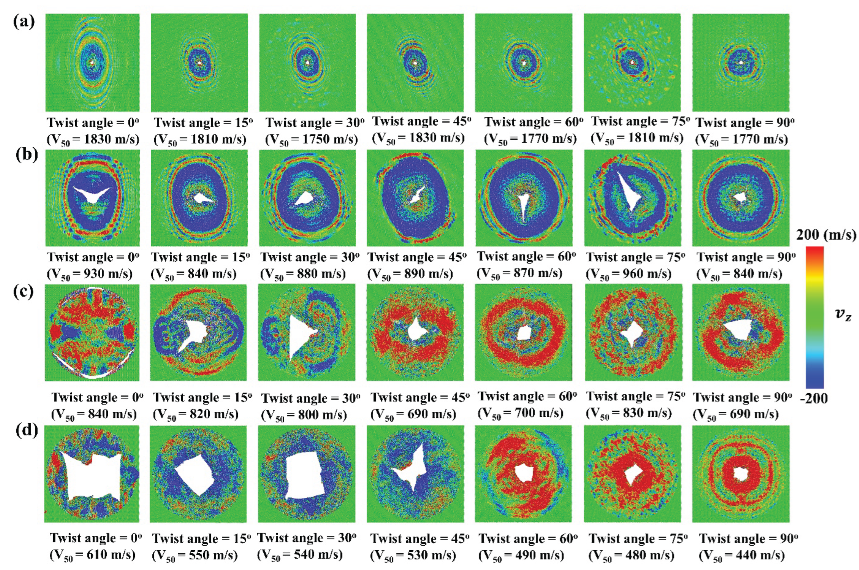
Figure 4 shows the residual velocity versus initial velocity for the diamond projectile with = 4 nm upon bilayer phosphorene membranes with different twist angles. It can be seen that, the curves can be roughly into two regions. Region I represents the scenario that the projectile cannot penetrate the membrane and bounce back. Moreover, in this region, the residual velocity changes linearly with the initial velocity . Region II represents the scenario that the projectile can penetrate the membrane far before the cone wave reaches the fixed boundary, in which the failure is local instead of global. It can be seen that, for different twist angles, the residual velocity almost coincides with each other associated with initial velocities . Note that, the critical velocity beyond which the projectile can penetrates the bilayer phosphorene membrane is ballistic limit, usually denoted as [42,58]. Here, for the diamond projectile with = 4 nm, the ballistic limit is around 1100 m/s regardless of the twist angle for the circular bilayer phosphorene membrane with = 48 nm. Figure 5 shows the fracture patterns of the phosphorene membranes under the ballistic limit. It can be seen that, although the cone wave fronts are in different shape for different twist angles, the structural failure happens before the cone wave reaches the boundary. Moreover, the fracture areas are all located in the collision center, indicating a local failure instead of a global failure.
3.2. Effect of Projectile Radius on the Impact Performance
In order to investigate the effect of projectile radius on the impact performance, CG models were applied to simulate ballistic impact of bilayer phosphorene membranes, in which the radius of the projectile ranges from 2 to 8 nm. Figure 6 shows the impact force versus time. As shown in Figure 6(a), the patterns of impact force evolution for = 2 nm are very similar to that of = 4 nm as shown in Figure 3(a). Specifically, the force curves are spike-like for = 2 nm and = 4 nm. Interestingly, the force curves are in different shapes for = 6 nm as shown in Figure 6(b), in which there are two spikes instead of one spike. Similar as < 4nm, the first spike for = 6 nm is attributed to the initial impact between the projectile and the phosphorene membrane. In contrast, the second spike in Figure 6(b) results from the reflection and interference of cone wave [42,58]. Fortunately, the second spike are not higher than the first spike in Figure 6(b). Therefore, the structure failure under the impact of projectiles with = 6 nm is still dominated by the initial collision between the projectile and the phosphorene membrane. Consequently, the structural failures are still local for = 6 nm.
Figure 6(c) shows the impact force of the diamond projectiles with = 8 nm upon bilayer phosphorene membranes. The whole force responses can be divided into two phases. In phase I, the impact force first increases and then decreases. In this phase, the force curves for different twist angles almost coincides with each other, in which there is no reflection and interference for the cone wave. In phase II, the second spike occurs and the curves deviates from each other. Due to different degrees of mismatch between the wavefront shape and the membrane shape, the reflection and interference are also different for bilayer phosphorene membranes with different twist angles. Specifically, the aforementioned mismatch for the twist angle equal to 90o is lowest. Therefore, the force amplification is highest for 90o as shown in Figure 6(c), in which the second spike is significantly higher than the first spike. Hence, the structure failure under the impact of projectiles with = 8 nm are dominated by the reflection and interference for the cone wave. As a result, the structural failure mode transitions from local to global. Figure 6(d) shows the impact force for the diamond projectiles with = 10 nm. Significantly, the force curve changes further in shape. However, the force curve can still be divided into two phases, in which the first phase is dominated by the initial collision between the projectile and the membrane while the second phase is dominated by the reflection and interference of cone wave.
Figure 7 shows the residual velocity versus initial velocity for = 10 nm. Similar as Figure 4, the curves can still be roughly into two regions. In region I, the curves are very close with each other. In this region, the relations between the residual velocity and the initial velocity are all linear while the slope of the curves increases almost monotonically as the twist angle increases. The above slope increase can be attributed to the increasingly high spikes from reflection and interference of cone wave as the initial velocity increases. In region II, the curves deviate from each other, in which global failure occurs due to reflection and interference of cone wave. Further, the ballistic limit are significantly different from each other for different twist angles. For example, the ballistic limit for 0o is 610 m/s while that for 90o is 440 m/s. More interestingly, there are two types of failure, in which one occurs when the projectile bounces back with relatively small while the other one occurs when the projectile penetrates the phosphorene membrane.
Figure 8 shows the impact resistance of bilayer phosphorene membranes for projectiles with different . For projectiles with ≤ 6 nm, the maximum impact force barely changes with the twist angle as shown in Figure 8(a). In contrast, for projectiles with ≥ 8 nm, the maximum impact force first fluctuates for the increase in twist angle from 0o to 60o, and then increases dramatically for the increase in twist angle from 60o to 90o. Figure 8(b) shows the inverse of the ballistic limit versus the twist angle for visualization and comparison with Figure 8(a). It can be seen that, for ≤ 6 nm, the inverse of the ballistic limit barely changes associated with the increase of the twist angle. As mentioned above, when the projectile radius is no bigger than 6 nm, the force amplification is either 0 or smaller than 1.0 from reflection and interference of cone wave, playing a marginal role in determining the ballistic limit . In contrast, when the projectile radius is no smaller than 8 nm, the force amplification starts to be bigger than 1.0, decreasing the ballistic limit . Therefore, as shown in Figure 8(b), the inverse of ballistic limit increase almost monotonically with the twist angle. In other words, the ballistic limit increases as the twist angle increases. Figure 9 shows the fracture patterns of the bilayer phosphorene membranes under the ballistic impact of projectiles with from 2 to 10nm. It can be seen that for ≤ 6 nm the structural failure is local while the structural failure is global for ≥ 8 nm.
4. Conclusions
In this work, CG MD simulations were adopted to study the effect of twist angle and projectile radius on the ballistic impact performance of bilayer phosphorene membranes with its radius equal to 48 nm. First, the projectile radius is fixed at 4 nm while the twist angle for the bilayer phosphorene membrane ranges from 0o to 90o. Results indicate that, the velocity distribution profiles and propagation of cone wave are different for membranes with different twist angles. When the twist angle is equal to 0o, the shape of the cone wave front is an ellipse with axial ratio equal to 1.44. As the twist angle increases from 0o to 90o, the shape of the cone wave front alters, in which the major axis rotates counterclockwise and the axial ratio keeps decreasing to 1.0. Despite the differences in impact dynamics, the twist angle plays a minor role in impact force profile, projectile velocity profile, and the ballistic limit, in which the structural failure is local instead of global. Second, the projectile radius is altered from 2 to 10 nm to investigate its effect on ballistic impact performance. For projectiles with ≤ 6 nm, the maximum impact force barely changes with the twist angle while the structural failure is local induced by the initial collision from the projectile. For projectiles with ≥ 8 nm, For projectiles with ≥ 8 nm, the maximum impact force first fluctuates for the increase in twist angle from 0o to 60o, and then increases dramatically for the increase in twist angle from 60o to 90o. Accordingly, the structural failure is global induced by the reflection and interference of cone wave. Moreover, due to different degrees of mismatch between the wavefront shape and the membrane shape, the reflection and interference are also different for bilayer phosphorene membranes with different twist angles. Specifically, the aforementioned mismatch for the twist angle equal to 90o is lowest, bringing the maximum force amplification and thus biggest ballistic limit reduction. For = 10 nm, the ballistic limit for 0o is 610 m/s while that for 90o is 440 m/s. Overall, our findings provide timely guidance for the design of future nanodevices using phosphorene with high impact resistance.
Author Contributions
Conceptualization, N.L. and L.W.; methodology, N.L.; software, K.H. and X. Y.; validation, D.X.; formal analysis, N.L.; investigation, N.L.; resources, N.L.; data curation, K.H., N.L. and X. Y.; writing—original draft preparation, N.L., K.H., and X. Y.; writing—review and editing, N.L., D.X. and L.W.; visualization, N.L. and K.H.; supervision, N.L., D.X. and L.W.; project administration, N.L. and L.W.; funding acquisition, N.L., D.X. and L.W. All authors have read and agreed to the published version of the manuscript.
Funding
N.L., L.W. and D.X. acknowledge support from National Natural Science Foundation of China under grant No. 12302185, 52205493, 12272270. D.X. also acknowledges support from the Aeronautical Science Foundation of China (ASFC) under the grant No. ASFC-20230016038001. This work is also sponsored by Shanghai Gaofeng Project for University Academic Program Development.
Data Availability Statement
Data will be made available on request.
Conflicts of Interest
The authors declare no conflicts of interest.
Abbreviations
The following abbreviations are used in this manuscript:
| 2D | Two-dimensional |
| CG | Coarse-grained |
| MD | Molecular dynamics |
References
- Bidhendi, M.R.T.; Behdinan, K. Graphene oxide coated silicon carbide films under projectile impacts. Int. J. Mech. Sci. 2023, 261. [Google Scholar] [CrossRef]
- Yang, Z.; Chiang, C.-C.; Meng, Z. Investigation of dynamic impact responses of layered polymer-graphene nanocomposite films using coarse-grained molecular dynamics simulations. Carbon 2022, 203, 202–210. [Google Scholar] [CrossRef]
- Sun, W.; Xue, S.; Jiang, J. Molecular dynamics study on the thermal conductivity and ballistic resistance of twisted graphene. Comput. Mater. Sci. 2023, 229. [Google Scholar] [CrossRef]
- Li, X.-L.; Guo, J.-G. Theoretical investigation on energy absorption of single-layer graphene under ballistic impact. Thin-Walled Struct. 2023, 191. [Google Scholar] [CrossRef]
- Shepelev, I.; Dmitriev, S.; Korznikova, E. Molecular dynamics simulation of high-speed loading of 2D boron nitride. Lett. Mater. 2021, 11, 79–83. [Google Scholar] [CrossRef]
- Xie, W.; Lee, J.-H. Intrinsic Dynamics and Toughening Mechanism of Multilayer Graphene upon Microbullet Impact. ACS Appl. Nano Mater. 2020, 3, 9185–9191. [Google Scholar] [CrossRef]
- Liu, N.; Becton, M.; Zhang, L.; Chen, H.; Zeng, X.; Pidaparti, R.; Wang, X. A coarse-grained model for mechanical behavior of phosphorene sheets. Phys. Chem. Chem. Phys. 2019, 21, 1884–1894. [Google Scholar] [CrossRef]
- Meng, Z.; Han, J.; Qin, X.; Zhang, Y.; Balogun, O.; Keten, S. Spalling-like failure by cylindrical projectiles deteriorates the ballistic performance of multi-layer graphene plates. Carbon 2018, 126, 611–619. [Google Scholar] [CrossRef]
- Yang, X.; Zhang, B. Twisted bilayer graphene/h-BN under impact of a nano-projectile. Appl. Surf. Sci. 2021, 538. [Google Scholar] [CrossRef]
- N. Suksangpanya, N.A. Yaraghi, D. Kisailus, P. Zavattieri, Twisting cracks in Bouligand structures, Journal of the Mechanical Behavior of Biomedical Materials 76 (2017) 38-57.
- Meng, Q.; Gao, Y.; Shi, X.; Feng, X.-Q. Three-dimensional crack bridging model of biological materials with twisted Bouligand structures. J. Mech. Phys. Solids 2022, 159. [Google Scholar] [CrossRef]
- N. Liu, R. Pidaparti, X. Wang, Abnormal linear elasticity in polycrystalline phosphorene, Physical Chemistry Chemical Physics 20(13) (2018) 8668-8675.
- Yang, Z.; Ma, F.; Xu, K. Grain boundaries guided vibration wave propagation in polycrystalline graphene. RSC Adv. 2017, 7, 24667–24673. [Google Scholar] [CrossRef]
- Liu, N.; Hong, J.; Zeng, X.; Pidaparti, R.; Wang, X. Fracture mechanisms in multilayer phosphorene assemblies: from brittle to ductile. Phys. Chem. Chem. Phys. 2017, 19, 13083–13092. [Google Scholar] [CrossRef]
- Liu, N.; Hong, J.; Pidaparti, R.; Wang, X. Abnormality in fracture strength of polycrystalline silicene. 2D Mater. 2016, 3, 035008. [Google Scholar] [CrossRef]
- Liu, N.; Hong, J.; Pidaparti, R.; Wang, X. Fracture patterns and the energy release rate of phosphorene. Nanoscale 2016, 8, 5728–5736. [Google Scholar] [CrossRef] [PubMed]
- Yazyev, O.V.; Chen, Y.P. Polycrystalline graphene and other two-dimensional materials. Nat. Nanotechnol. 2014, 9, 755–767. [Google Scholar] [CrossRef] [PubMed]
- Song, Z.; Artyukhov, V.I.; Yakobson, B.I.; Xu, Z. Pseudo Hall–Petch Strength Reduction in Polycrystalline Graphene. Nano Lett. 2013, 13, 1829–1833. [Google Scholar] [CrossRef]
- Ahmadi, H.; Liaghat, G.; Charandabi, S.C. High velocity impact on composite sandwich panels with nano-reinforced syntactic foam core. Thin-Walled Struct. 2020, 148. [Google Scholar] [CrossRef]
- Cheng, Y.; Dong, J.; Xiao, K.; Jiang, M.; Huang, C.; Wu, X. Impact behavior of advanced films under micro- and nano-scales: A review. Thin-Walled Struct. 2024, 205. [Google Scholar] [CrossRef]
- Evans, K.M.; Chen, S.H.; Souna, A.J.; Stranick, S.J.; Soles, C.L.; Chan, E.P. The Projectile Perforation Resistance of Materials: Scaling the Impact Resistance of Thin Films to Macroscale Materials. ACS Appl. Mater. Interfaces 2023, 15, 32916–32925. [Google Scholar] [CrossRef]
- Xiao, K.; Yin, Q.; Wu, X.; Huang, C. Mechanical behavior of single-layer graphdiyne via supersonic micro-projectile impact. Nano Mater. Sci. 2022, 4, 383–392. [Google Scholar] [CrossRef]
- Bowman, A.L.; Chan, E.P.; Lawrimore, W.B.; Newman, J.K. Supersonic Impact Response of Polymer Thin Films via Large-Scale Atomistic Simulations. Nano Lett. 2021, 21, 5991–5997. [Google Scholar] [CrossRef]
- Zhu, Y.; Giuntoli, A.; Hansoge, N.; Lin, Z.; Keten, S. Scaling for the inverse thickness dependence of specific penetration energy in polymer thin film impact tests. J. Mech. Phys. Solids 2022, 161. [Google Scholar] [CrossRef]
- White, H.L.; Giuntoli, A.; Fermen-Coker, M.; Keten, S. Tailoring flake size and chemistry to improve impact resistance of graphene oxide thin films. Carbon 2023, 215. [Google Scholar] [CrossRef]
- Sardar, B.; Singh, S.P.; Mahajan, P. Influence of temperature and size of the projectile on perforation of graphene sheet under transverse impact using molecular dynamics. Mater. Today Commun. 2023, 35. [Google Scholar] [CrossRef]
- Zhang, Y.; Qiu, Y.; Niu, F.; Ademiloye, A. Molecular dynamics simulation of perforation of graphene under impact by fullerene projectiles. Mater. Today Commun. 2022, 31. [Google Scholar] [CrossRef]
- Liu, T.; Chen, L.; Zhang, X.; Zhang, X.; Qiu, X. Stress wave response in a two-dimensional membrane subjected to hypervelocity impact of a micro-flyer. Int. J. Impact Eng. 2022, 167. [Google Scholar] [CrossRef]
- Xie, Z.; Fu, X.; Zhang, Q.; Liu, L.; Zhu, X.; Ren, Y.; Chen, W. Ballistic performance of additive manufacturing metal lattice structures. Thin-Walled Struct. 2024, 208. [Google Scholar] [CrossRef]
- Yang, W.; Huang, R.; Liu, J.; Liu, J.; Huang, W. Ballistic impact responses and failure mechanism of composite double-arrow auxetic structure. Thin-Walled Struct. 2022, 174. [Google Scholar] [CrossRef]
- Zheng, X.; Wu, H.; Li, X.; Hu, Q.; Yan, K.; Qi, S.; Yuan, M. Experimental and numerical study on ballistic response of stitched aramid woven fabrics under normal and oblique dynamic impact. Thin-Walled Struct. 2024, 205. [Google Scholar] [CrossRef]
- Dhakal, K.P.; Tran, T.T.; Lee, T.; Choi, W.; Peterson, S.F.; Marmolejo-Tejada, J.M.; Bahng, J.; Lee, D.; Dat, V.K.; Kim, J.; et al. Giant Modulation of Interlayer Coupling in Twisted Bilayer ReS2. Adv. Sci. 2025, 12, e2500411. [Google Scholar] [CrossRef]
- Zhang, Y.; An, M.; Song, D.; Fan, A.; Chen, D.; Wang, H.; Ma, W.; Zhang, X. Phonon magic angle in two-dimensional puckered homostructures. J. Mater. Chem. C 2021, 9, 12741–12750. [Google Scholar] [CrossRef]
- Sung, S.H.; Goh, Y.M.; Yoo, H.; Engelke, R.; Xie, H.; Zhang, K.; Li, Z.; Ye, A.; Deotare, P.B.; Tadmor, E.B.; et al. Torsional periodic lattice distortions and diffraction of twisted 2D materials. Nat. Commun. 2022, 13, 1–8. [Google Scholar] [CrossRef]
- Bøggild, P.; Booth, T.J. The delicate art of twisting 2D materials. Newton 2025, 1. [Google Scholar] [CrossRef]
- Feng, H.F.; Liu, B.; Guo, Z.-X. Giant twist-angle dependence of thermal conductivity in bilayer graphene originating from strong interlayer coupling. Phys. Rev. B 2023, 108, L241405. [Google Scholar] [CrossRef]
- Kapfer, M.; Jessen, B.S.; Eisele, M.E.; Fu, M.; Danielsen, D.R.; Darlington, T.P.; Moore, S.L.; Finney, N.R.; Marchese, A.; Hsieh, V.; et al. Programming twist angle and strain profiles in 2D materials. Science 2023, 381, 677–681. [Google Scholar] [CrossRef]
- Xin, K.; Wang, X.; Grove-Rasmussen, K.; Wei, Z. Twist-angle two-dimensional superlattices and their application in (opto)electronics. J. Semicond. 2022, 43. [Google Scholar] [CrossRef]
- Caviness, C.; Chen, Y.; Yang, Z.; Wang, H.; Wu, Y.; Meng, Z. Improved Ballistic Impact Resistance of Nanofibrillar Cellulose Films With Discontinuous Fibrous Bouligand Architecture. J. Appl. Mech. 2023, 91. [Google Scholar] [CrossRef]
- Qin, X.; Marchi, B.C.; Meng, Z.; Keten, S. Impact resistance of nanocellulose films with bioinspired Bouligand microstructures. Nanoscale Adv. 2019, 1, 1351–1361. [Google Scholar] [CrossRef]
- Lee, J.-H.; Loya, P.E.; Lou, J.; Thomas, E.L. Dynamic mechanical behavior of multilayer graphene via supersonic projectile penetration. Science 2014, 346, 1092–1096. [Google Scholar] [CrossRef]
- Meng, Z.; Singh, A.; Qin, X.; Keten, S. Reduced ballistic limit velocity of graphene membranes due to cone wave reflection. Extreme Mech. Lett. 2017, 15, 70–77. [Google Scholar] [CrossRef]
- Zhang, Y.; Meng, Z.; Qin, X.; Keten, S. Ballistic impact response of lipid membranes. Nanoscale 2018, 10, 4761–4770. [Google Scholar] [CrossRef]
- Singh, A.; Keten, S. Analysis of Cone Wave Reflection in Finite-Size Elastic Membranes and Extension of the Ballistic Impact Problem From Elastic to Viscoelastic Membranes. J. Appl. Mech. 2018, 85, 081004. [Google Scholar] [CrossRef]
- Gürel, U.; Keten, S.; Giuntoli, A. Bidispersity Improves the Toughness and Impact Resistance of Star-Polymer Thin Films. ACS Macro Lett. 2024, 13, 302–307. [Google Scholar] [CrossRef] [PubMed]
- White, H.L.; Giuntoli, A.; Fermen-Coker, M.; Keten, S. Tailoring flake size and chemistry to improve impact resistance of graphene oxide thin films. Carbon 2023, 215. [Google Scholar] [CrossRef]
- Zhu, P.; Lin, J.; Xiao, R.; Zhou, H. Unravelling physical origin of the Bauschinger effect in glassy polymers. J. Mech. Phys. Solids 2022, 168. [Google Scholar] [CrossRef]
- Pal, S.; Keten, S. Micro-ballistic response of thin film polymer grafted nanoparticle monolayers. Soft Matter 2024, 20, 7926–7935. [Google Scholar] [CrossRef]
- Yoon, K.; Ostadhossein, A.; van Duin, A.C. Atomistic-scale simulations of the chemomechanical behavior of graphene under nanoprojectile impact. Carbon 2016, 99, 58–64. [Google Scholar] [CrossRef]
- Haque, B.Z. (.; Chowdhury, S.C.; Gillespie, J.W. Molecular simulations of stress wave propagation and perforation of graphene sheets under transverse impact. Carbon 2016, 102, 126–140. [Google Scholar] [CrossRef]
- Bidhendi, M.R.T.; Behdinan, K. High-velocity transverse impact of monolayer graphene oxide by a molecular dynamics study. Comput. Mater. Sci. 2022, 216. [Google Scholar] [CrossRef]
- Li, X.-L.; Guo, J.-G. Theoretical investigation on energy absorption of single-layer graphene under ballistic impact. Thin-Walled Struct. 2023, 191. [Google Scholar] [CrossRef]
- A.C.T. van Duin, A. Strachan, S. Stewman, Q.S. Zhang, X. Xu, W.A. Goddard, ReaxFFSiO reactive force field for silicon and silicon oxide systems, Journal of Physical Chemistry A 107(19) (2003) 3803-3811.
- Brenner, D.W.; Shenderova, O.A.; Harrison, J.A.; Stuart, S.J.; Ni, B.; Sinnott, S.B. A second-generation reactive empirical bond order (REBO) potential energy expression for hydrocarbons. J. Phys. Condens. Matter 2002, 14, 783–802. [Google Scholar] [CrossRef]
- Stuart, S.J.; Tutein, A.B.; Harrison, J.A. A reactive potential for hydrocarbons with intermolecular interactions. J. Chem. Phys. 2000, 112, 6472–6486. [Google Scholar] [CrossRef]
- Meng, Z.; Bessa, M.A.; Xia, W.; Liu, W.K.; Keten, S. Predicting the Macroscopic Fracture Energy of Epoxy Resins from Atomistic Molecular Simulations. Macromolecules 2016, 49, 9474–9483. [Google Scholar] [CrossRef]
- Xia, K.; Zhan, H.; Hu, D.; Gu, Y. Failure mechanism of monolayer graphene under hypervelocity impact of spherical projectile. Sci. Rep. 2016, 6, 33139. [Google Scholar] [CrossRef]
Figure 1.
Coarse-grained (CG) model for the impact of bilayer phosphorene membranes by diamond projectiles. (a) Overview of the CG model of the bilayer phosphorene membrane and the spherical diamond projectile; (b) Snapshot of the diamond projectiles with radius ranging from 2 to 10 nm; (c) Top view of the bilayer phosphorene membranes with different twist angles; (d) Radial distribution function of the bilayer phosphorene sheets with different twist angles.
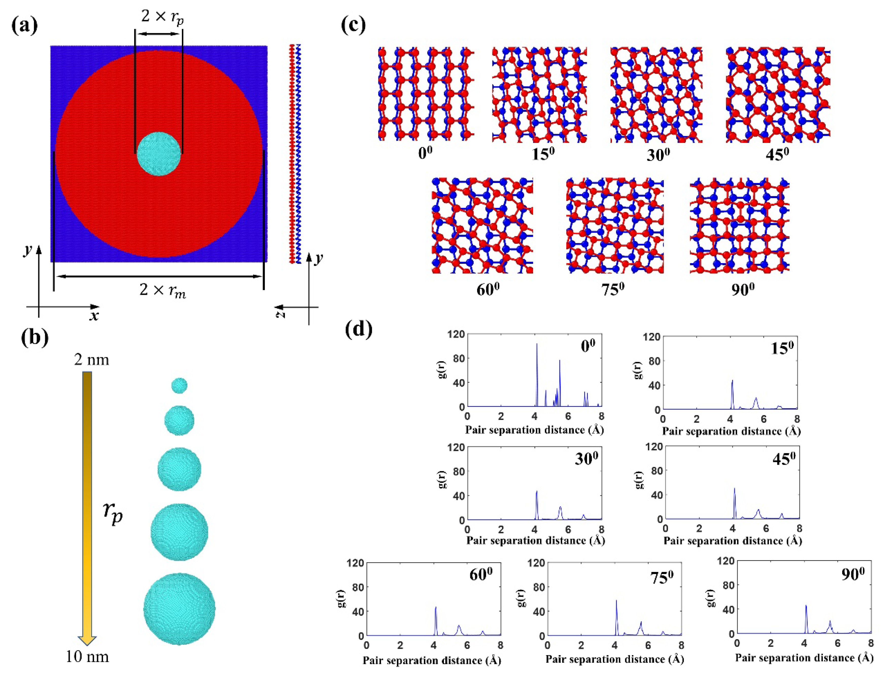
Figure 2.
Velocity contours of the bilayer phosphorene membranes with different twist angles during impact of a diamond projectile with its radius = 4 nm (The initial velocity of the projectile, , is 800 m/s).
Figure 2.
Velocity contours of the bilayer phosphorene membranes with different twist angles during impact of a diamond projectile with its radius = 4 nm (The initial velocity of the projectile, , is 800 m/s).
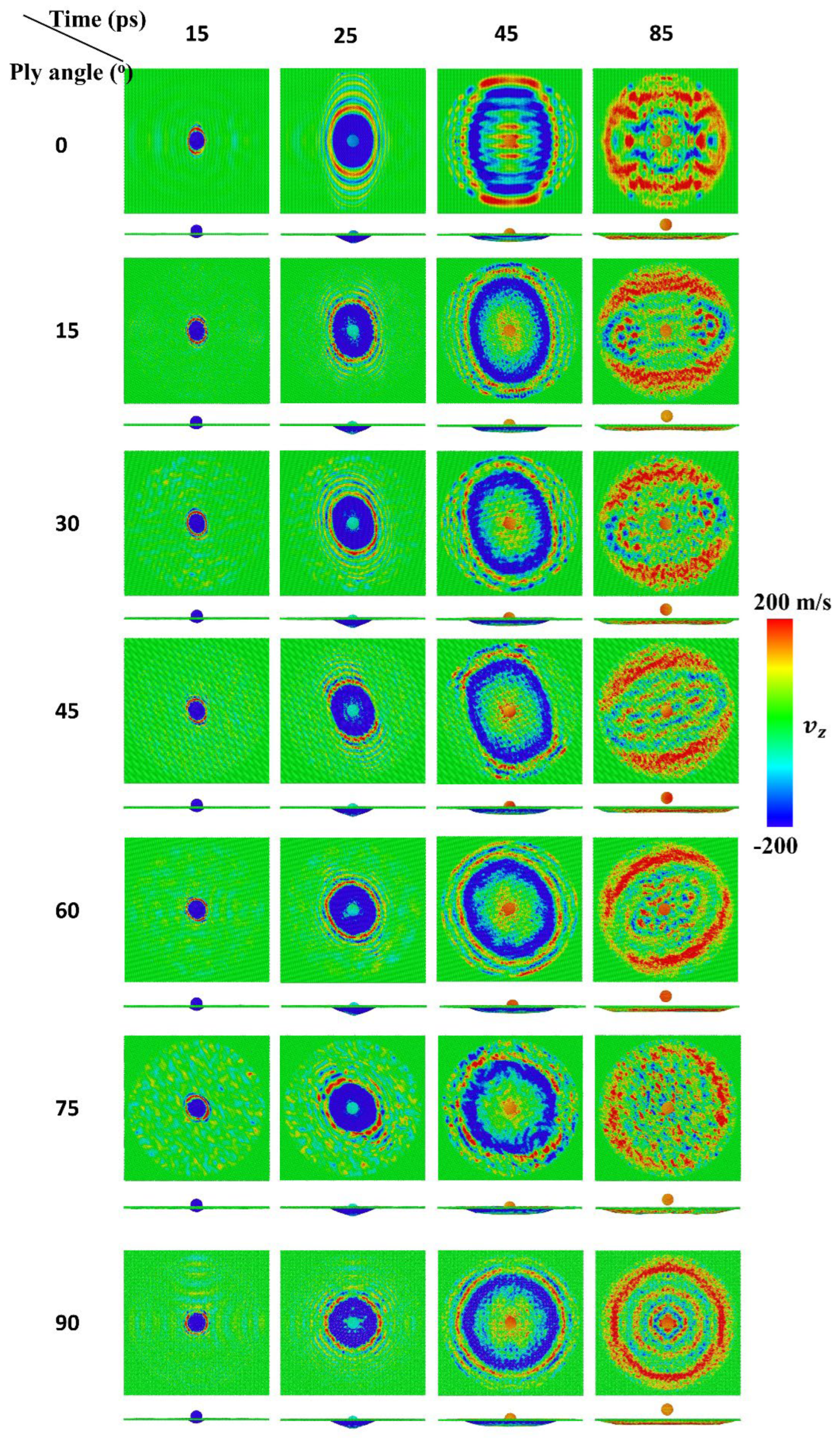
Figure 3.
Impact dynamics of the diamond projectile with its radius = 4 nm upon bilayer phosphorene membranes with different twist angles (a) the impact force profiles of the diamond projectile when the initial velocity = 800 m/s; (b) maximum impact force versus twist angle; (c) the projectile velocity profiles of the diamond projectile when the initial velocity = 800 m/s; (d) residual velocity versus twist angle.
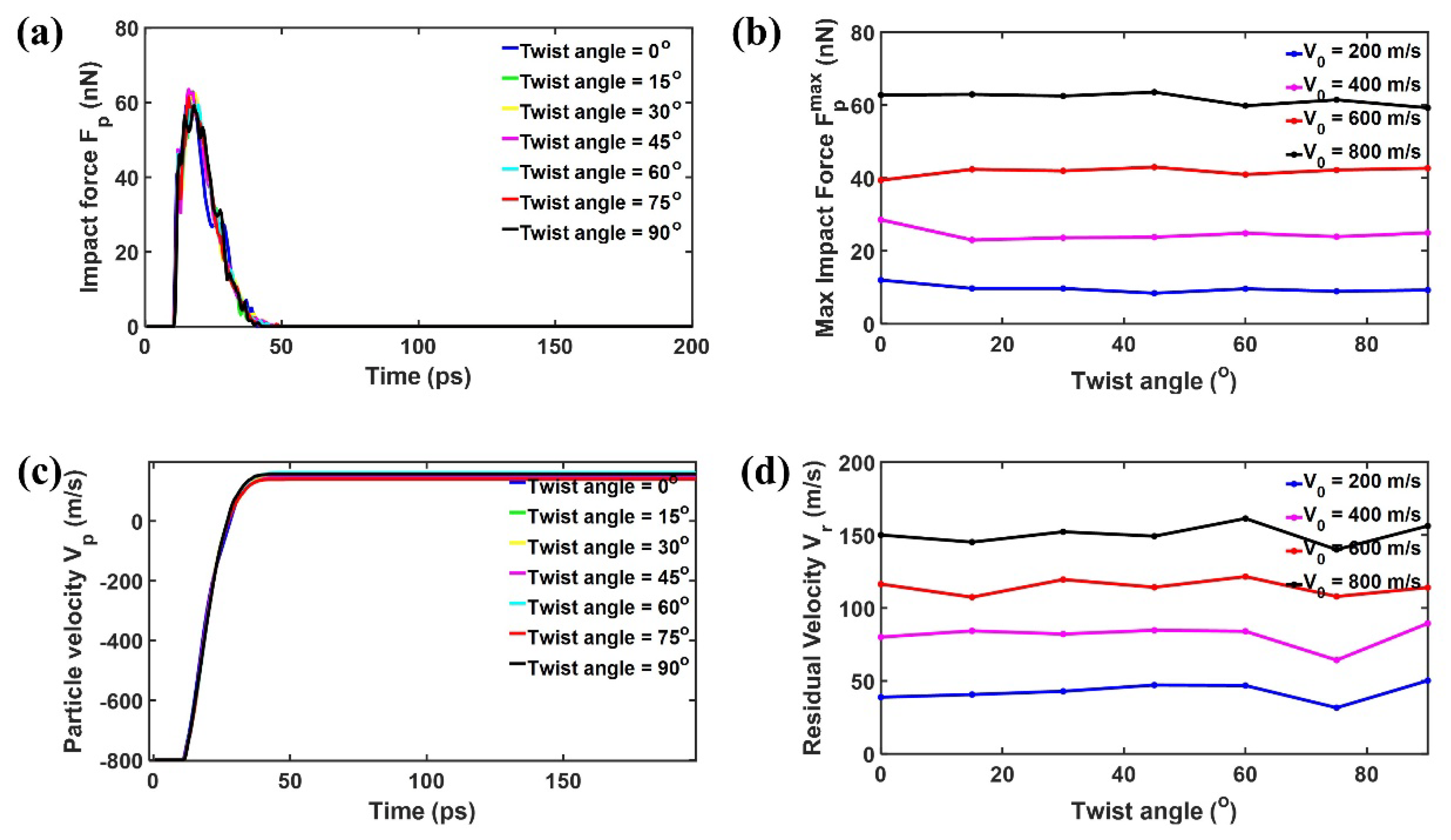
Figure 4.
Residual velocity versus initial velocity of the diamond projectile with its radius = 4 nm upon bilayer phosphorene membranes with different twist angles.
Figure 4.
Residual velocity versus initial velocity of the diamond projectile with its radius = 4 nm upon bilayer phosphorene membranes with different twist angles.
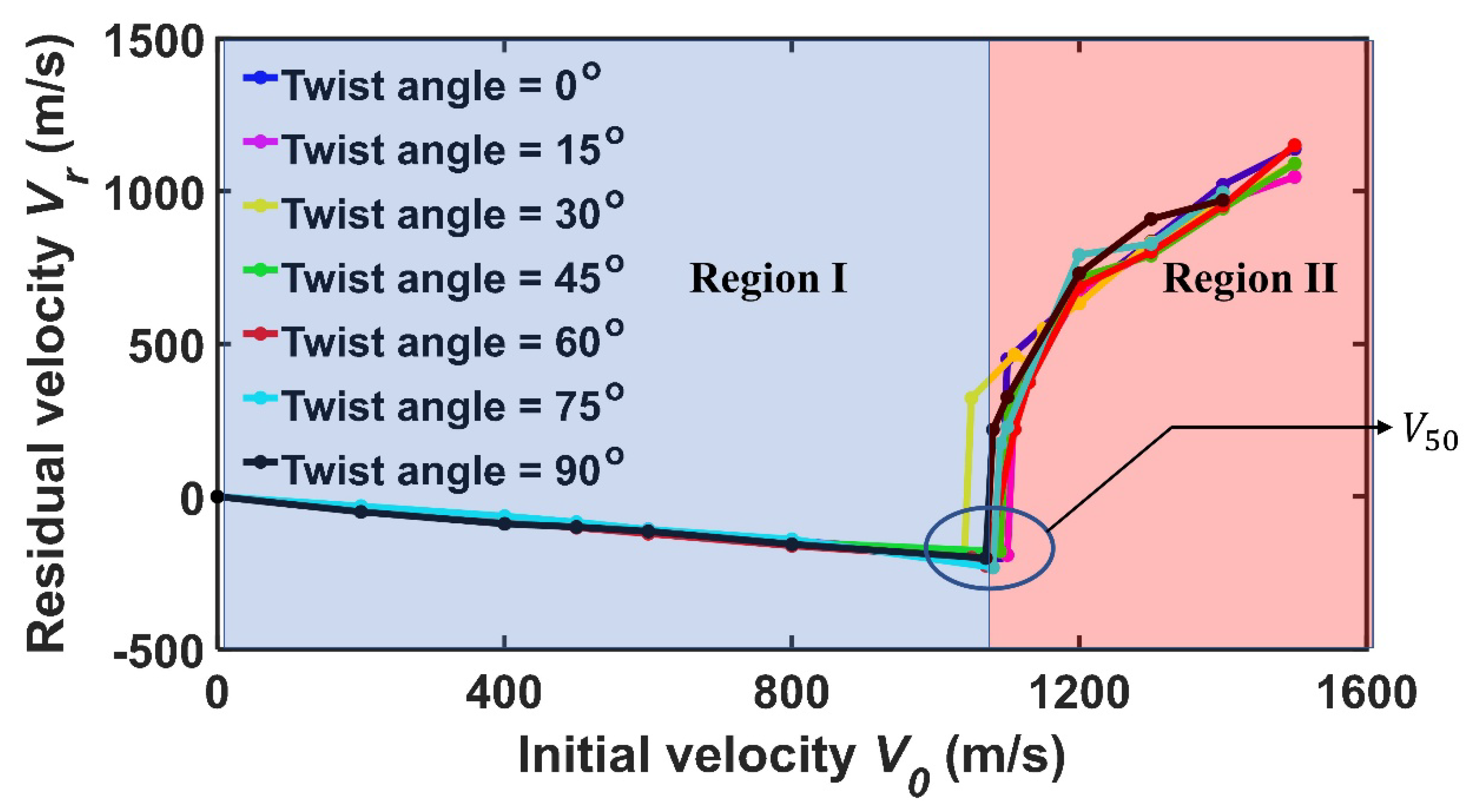
Figure 5.
Fracture patterns of the bilayer phosphorene membranes with different twist angles under the impact of the diamond projectile with its radius = 4 nm when the initial velocity is equal to the ballistic limit .
Figure 5.
Fracture patterns of the bilayer phosphorene membranes with different twist angles under the impact of the diamond projectile with its radius = 4 nm when the initial velocity is equal to the ballistic limit .
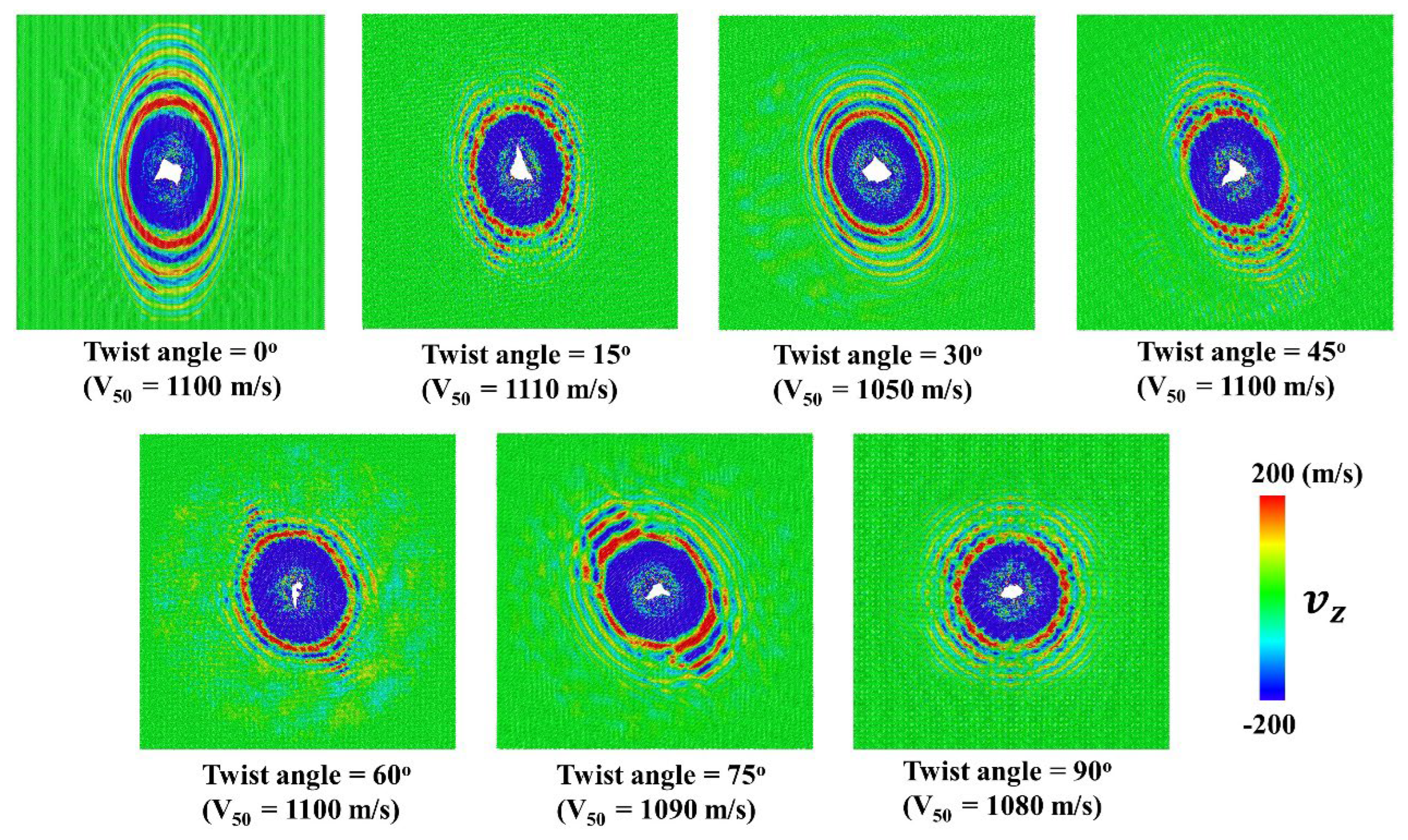
Figure 6.
The impact force of the diamond projectiles with different upon bilayer phosphorene membranes with different twist angles. (a) = 2 nm, = 800 m/s; (b) = 6 nm, = 800 m/s; (c) = 8 nm, = 600 m/s; (d) = 10 nm, = 400 m/s.
Figure 6.
The impact force of the diamond projectiles with different upon bilayer phosphorene membranes with different twist angles. (a) = 2 nm, = 800 m/s; (b) = 6 nm, = 800 m/s; (c) = 8 nm, = 600 m/s; (d) = 10 nm, = 400 m/s.
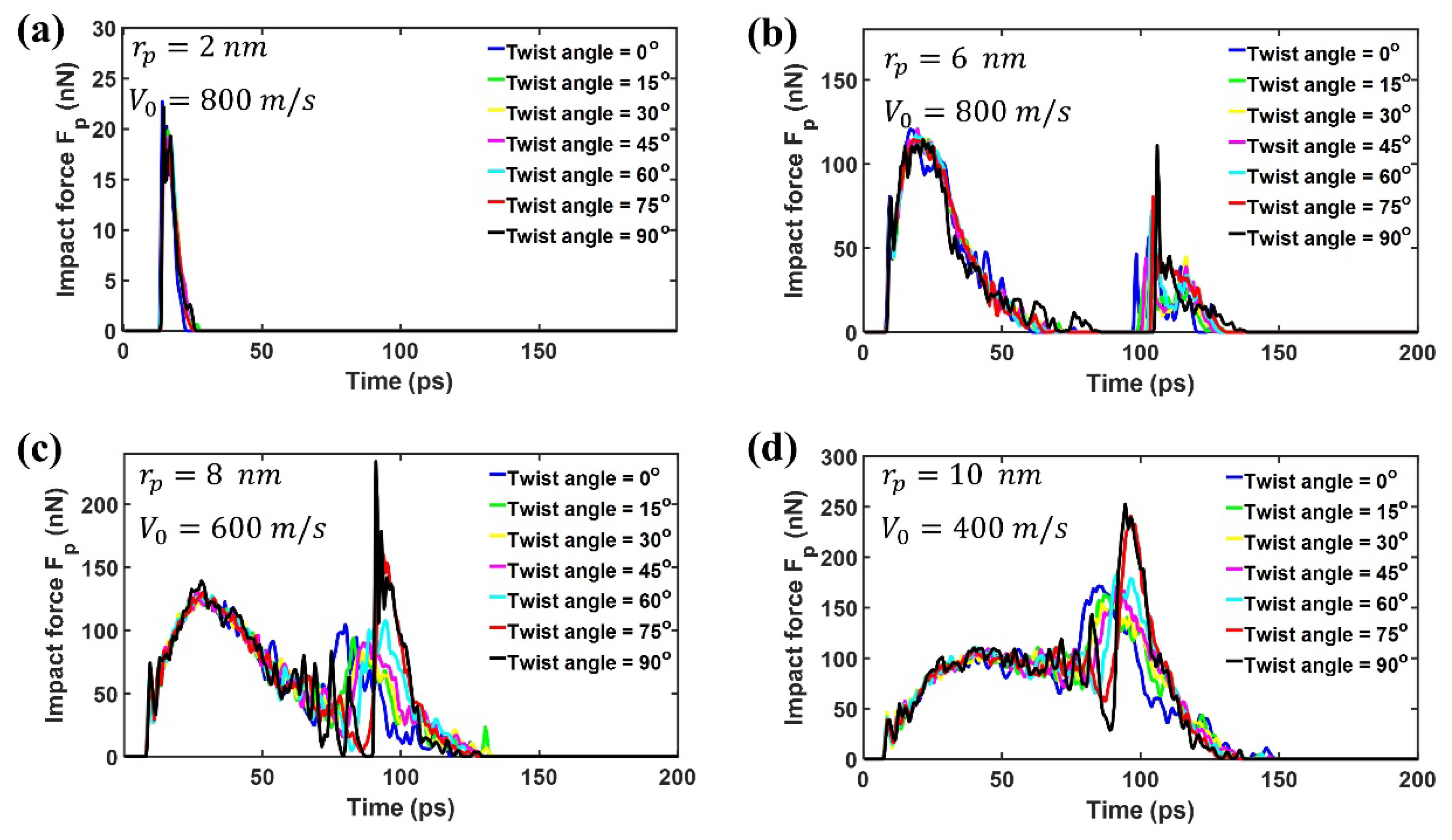
Figure 7.
Residual velocity versus initial velocity of the diamond projectile with its radius = 10 nm upon bilayer phosphorene membranes with different twist angles.
Figure 7.
Residual velocity versus initial velocity of the diamond projectile with its radius = 10 nm upon bilayer phosphorene membranes with different twist angles.
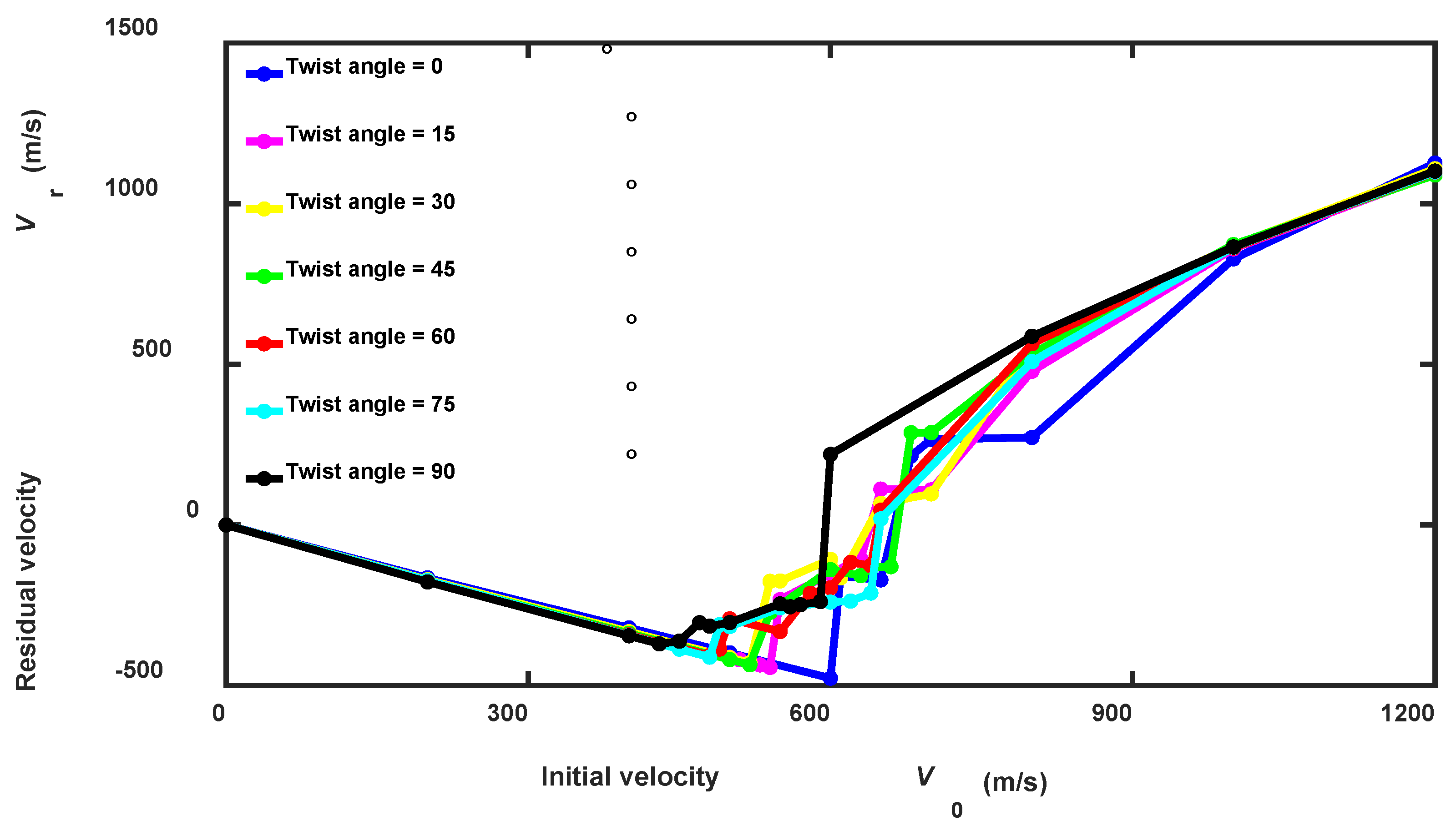
Figure 8.
Impact resistance of bilayer phosphorene membranes for projectiles with different . (a) maximum impact force versus twist angle; (b) the inverse of the ballistic limit versus twist angle.
Figure 8.
Impact resistance of bilayer phosphorene membranes for projectiles with different . (a) maximum impact force versus twist angle; (b) the inverse of the ballistic limit versus twist angle.
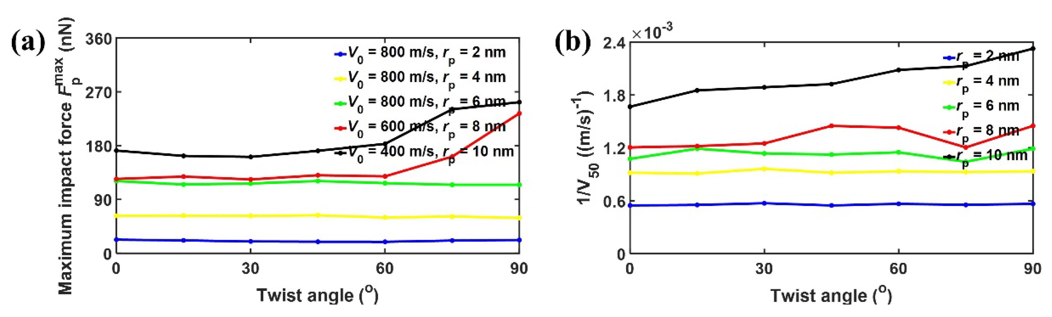
Figure 9.
Fracture patterns of the bilayer phosphorene membranes with different twist angles under the impact of the diamond projectile with different radius when the initial velocity is equal to the ballistic limit (a) = 2 nm; (b) = 6 nm; (c) = 8 nm; (d) = 10 nm.
Figure 9.
Fracture patterns of the bilayer phosphorene membranes with different twist angles under the impact of the diamond projectile with different radius when the initial velocity is equal to the ballistic limit (a) = 2 nm; (b) = 6 nm; (c) = 8 nm; (d) = 10 nm.
Disclaimer/Publisher’s Note: The statements, opinions and data contained in all publications are solely those of the individual author(s) and contributor(s) and not of MDPI and/or the editor(s). MDPI and/or the editor(s) disclaim responsibility for any injury to people or property resulting from any ideas, methods, instructions or products referred to in the content. |
© 2025 by the authors. Licensee MDPI, Basel, Switzerland. This article is an open access article distributed under the terms and conditions of the Creative Commons Attribution (CC BY) license (http://creativecommons.org/licenses/by/4.0/).
Copyright: This open access article is published under a Creative Commons CC BY 4.0 license, which permit the free download, distribution, and reuse, provided that the author and preprint are cited in any reuse.


