Submitted:
15 August 2025
Posted:
19 August 2025
You are already at the latest version
Abstract
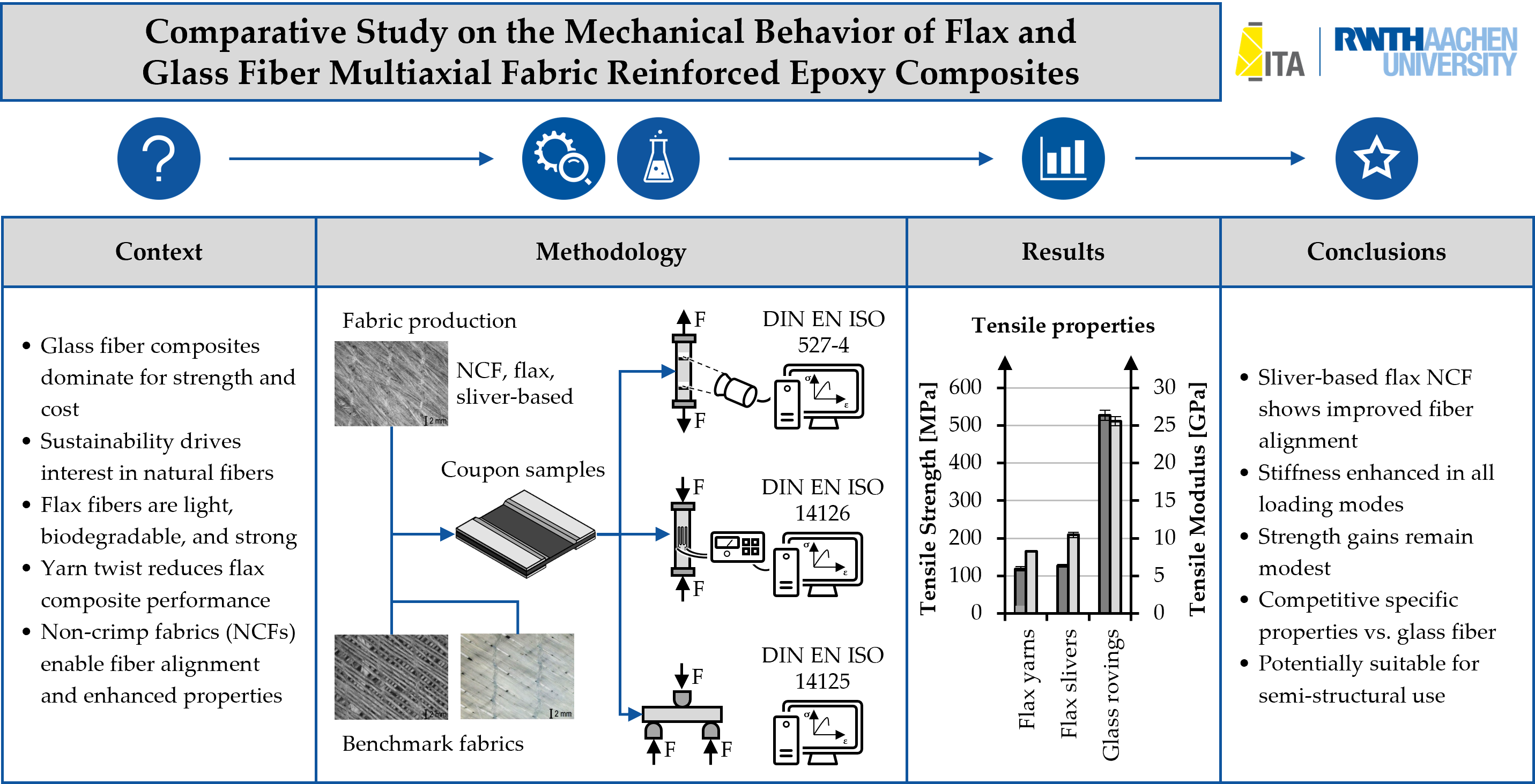
This study presents a comparative investigation of the mechanical performance of epoxy-based composites reinforced with ±45° multiaxial non-crimp fabrics (NCFs) made from natural flax fibers and conventional glass fibers. Flax fibers, despite their attractive sustainability profile and favorable specific mechanical properties, are typically processed into twisted yarns for textile reinforcement, which compromises fiber alignment and reduces composite performance. A novel yarn-free flax NCF was developed using false twist stabilization of aligned slivers to eliminate the negative effects of yarn twist. Composite laminates were manufactured via vacuum-assisted resin infusion (VARI) and tested for tensile, compressive and flexural behavior. The results show that, although glass fiber composites exhibit superior absolute strength and stiffness, flax-based NCF composites offer competitive specific properties and benefit significantly from improved fiber alignment compared to yarn-based variants. This work provides a systematic comparison under standardized conditions and confirms the mechanical feasibility of flax NCFs for semi-structural lightweight applications.
Keywords:
flax fiber
; glass fiber
; fiber composites
; non-crimp fabric
; sustainability
; mechanical properties
1. Introduction
Fiber-reinforced composites (FRCs) are extensively used in automotive, aerospace, and sports applications due to their high specific strength and stiffness, enabling substantial weight savings over traditional materials. Among them, glass fiber-reinforced composites (GFRCs) are dominant due to their excellent mechanical performance and cost-effectiveness [1]. However, the increasing need for sustainable and renewable materials has driven research toward natural fiber-reinforced composites (NFRCs), particularly those reinforced with bast fibers such as flax, hemp, and jute [2,3,4]. Flax fibers are among the most studied natural reinforcements due to their high tensile stiffness, low density, biodegradability, and relatively low energy requirement during production [5]. The intrinsic tensile modulus of flax can reach up to 80 GPa, with tensile strengths exceeding 1000 MPa under ideal conditions [6]. However, these values are rarely retained in composite form, primarily due to the influence of fiber processing and architecture [7].
One critical limitation of flax fiber-reinforced composites lies in the textile processing. The transformation of technical fibers into spun yarns involves twist insertion, which leads to fiber misalignment and increased crimp. Both factors reduce the effective load-bearing capacity of the fibers in composite matrices [8,9]. Pickering et al. [3] and Rayyaan et al. [7] highlight that avoiding twisting and minimizing processing damage are key factors to transferring the intrinsic fiber properties into the composite part. Shah [10] emphasized that the deviation of fiber orientation from the loading direction has a detrimental impact on tensile properties. Moreover, crimp and waviness—typical in woven fabrics—introduce stress concentrations that reduce compressive and shear strength [11].
To mitigate issues such as fiber undulation and misalignment, non-crimp fabrics (NCFs) directly produced from natural fiber slivers have emerged as a promising solution. NCFs consist of aligned fiber layers held together by stitching yarns, thereby minimizing crimp and making better use of the intrinsic fiber properties. Studies on NCFs have demonstrated significantly improved mechanical performance compared to woven equivalents [7,12].
However, applying this concept to flax slivers—loosely assembled, untwisted bundles of parallel fibers obtained during carding or combing—remains challenging due to their lower cohesion and reduced processing robustness compared to yarns or synthetic rovings. A fully industrializable multiaxial NCF concept based exclusively on untwisted flax slivers has yet to be realized. Furthermore, despite the potential of such architectures, systematic mechanical comparisons between flax and glass fiber NCF composites—particularly under equivalent fiber orientations and matrix systems—are scarce. Most comparative studies differ in fabric architecture, resin type, or manufacturing process, making direct benchmarking difficult [13].
The objective of this study is to address this research gap by developing a ±45° flax NCF using a novel yarn-free production process based on false twist stabilization. The resulting flax/epoxy laminates are mechanically characterized and benchmarked against reference glass NCF composites produced under identical conditions. This work investigates the feasibility of replacing glass fibers in multiaxial load-bearing structures with aligned flax reinforcements and assesses the mechanical potential of flax composites when textile-induced deficiencies are minimized.
2. Materials and Methods
2.1. Textile Reinforcements
This study evaluates three types of NCFs (Table 1). A commercially available E-glass NCF made from continuous rovings serves as the mechanical performance benchmark. A second NCF, produced from twisted flax yarns, represents the current industrial standard for NFRCs. The third material is a flax NCF manufactured from untwisted flax slivers using a novel, yarn-free processing route described in Section 2.2.
2.2. Production of the Sliver-Based Flax NCF
The sliver-based flax NCF was manufactured on a Copcentra MAX 3 CNC multi-axial warp-knitting machine (LIBA Maschinenfabrik GmbH, Germany; now part of KARL MAYER Holding SE & Co. KG, Germany) that was modified at the Institut für Textiltechnik (ITA) of RWTH Aachen University, Germany. A detailed description of the modification is provided in [14]. The setup is shown in Figure 1.
The process begins with the sliver feeding unit, which ensures continuous, twist-free delivery of flax slivers from a rotating can. These slivers pass through a false-twist unit, where they are temporarily twisted to provide consolidation and improved handling during feeding. The consolidated slivers are then transferred to the weft carrier, which lays them at ±45° orientations onto a supporting polyester grid to achieve the desired reinforcement architecture. Subsequently, the layers are secured in place by the stitching unit using polyester stitching yarns. Finally, the completed NCF is collected by the winding unit, where it is wound onto rolls for storage and further processing. An overview is given in Table 2.
2.3. Fiber Orientation
Load-appropriate alignment of reinforcing fibers is one of the most critical factors for achieving high mechanical performance in FRCs. A well-defined fiber orientation in the NCF is therefore of particular importance. At present, there is no standardized test method for determining the fiber orientation of textile reinforcements. In this study, the local fiber orientation is assessed by analyzing images of the NCF surfaces. Image evaluation is performed using the open-source software ImageJ in combination with the OrientationJ plugin [15,16,17]. The local orientation is calculated from brightness gradients in grayscale images based on structure tensors. A detailed description of this method is provided in [15,16,18]. The used test procedure is illustrated in Figure 2. The determination of fiber orientation is based on the evaluation of 24 overlays per material variant. The alignment of the images was carried out according to the stitching yarn paths in the direction of NCF production (0°). The tests were conducted at room temperature.
2.4. Composite Manufacturing
All three NCF types were processed into composite laminates using vacuum-assisted resin infusion (VARI). The epoxy system consists of EPIKOTE™ RIM R135 and the hardener EPIKURE™ RIM H137, both supplied by Hexion Inc., USA. The components were mixed at a weight ratio of 100:30. The system offers a pot life of approximately 300 minutes and cures to a density of around 1.15 g/cm³. For tensile and compressive testing, end tabs were bonded using the two-component adhesive ARALDITE® 2011 GB from Huntsman Corp., USA. Test specimens were cut using a water-cooled circular saw type K680 from MAIKO Engineering GmbH, Germany. The processing sequence for manufacturing the coupon specimens was as follows:
- Lay-up of four NCF plies in a [0/90]₄ stacking sequence;
- Drying in a hot-air oven at 80 °C for 30 minutes;
- Integration into VARI setup, including peel ply, flow media, and vacuum bagging;
- Resin infusion at ambient temperature under a vacuum of approximately –0.9 bar;
- Bonding of end tabs for tensile and compressive testing;
- Post-curing at 80 °C for 10 hours;
- Application of strain gauges for compressive testing.
2.5. Mechanical Testing
To evaluate the mechanical performance of the composite laminates, standardized tensile, compressive and flexural tests were conducted.
2.5.1. Tensile Testing
Tensile strength and stiffness of the three material variants were determined in accordance with DIN EN ISO 527-4 [19] using type 3 specimens equipped with glass fiber-reinforced plastic end tabs. Tests were carried out on a Z100 universal testing machine (ZwickRoell GmbH & Co. KG, Germany) equipped with a 100 kN load cell and wedge grips. Deformation was measured using an RTSS video extensometer (LIMESS Messtechnik und Software GmbH, Germany). The samples were subjected to a preload of 100 N. The testing speed was 2 mm/min.
2.5.2. Compressive Testing
Compressive properties were determined in accordance with DIN EN ISO 14126 [20] using type B1 specimens with bonded glass fiber-reinforced plastic end tabs. Testing followed method 2, applying a combination of shear stress and end-load-induced compression. Longitudinal strain was recorded using strain gauges of type FLAB-3-11-1LJCT-F (Tokyo Measuring Instruments Laboratory Co., Ltd., Japan), applied symmetrically on both sides of the specimen. Tests were performed on a Z100 universal testing machine equipped with a 100 kN load cell and an HCCF hydraulic compression fixture for composite materials (ZwickRoell GmbH & Co. KG, Germany).
No preload was applied during testing. The crosshead speed was set to 1 mm/min, and specimens were loaded until failure. A drop in force of 30% relative to the maximum recorded load was defined as the termination criterion. Specimens exhibiting clamp failure or a deflection exceeding 10% were considered invalid. Deflection was calculated from the compressive strain values recorded by the strain gauges mounted on the front and rear faces of the specimen.
2.5.3. Flexural Testing
Flexural properties were determined using three-point bending tests in accordance with DIN EN ISO 14125 [21]. The tested materials were assigned to material class III. Testing was performed on a type 1455 universal testing machine (ZwickRoell GmbH & Co. KG, Germany) equipped with a 1 kN load cell. The supports and bending punch each had a radius of 5 mm. Specimens were positioned such that the outermost fiber layer on the tension side faced downward. Deflection was recorded via the crosshead displacement of the testing machine. Testing was terminated upon visible specimen failure or a drop in force of 30% relative to the maximum load. Relevant specimen dimensions and test setup parameters are listed in Table 3. The test speed was 2 mm/min. After testing, failure modes were determined based on visual inspection of the fracture surfaces.
2.6. Fiber Volume Content and Composite Density
The fiber volume content (FVC) of the laminates was calculated based on the total plate mass, the mass of the NCF reinforcements, and the densities of both the epoxy matrix and the reinforcing fibers. The composite density ρVi was derived analytically using the determined global fiber volume content φFi, the matrix density ρMi, and the respective fiber density φFi, according to Equation (1). Porosity was not considered in this calculation.
ρVi = φFi ∙ ρFi + (1 - φFi) ∙ ρMi
3. Results
3.1. Fiber Orientation
Table 4 summarizes the average local fiber orientation and the absolute deviation from the target angle of 45° for all investigated NCF variants. For the flax fiber NCFs, individual measurements deviate by up to 6.6° from the target orientation. In the yarn-based flax NCF, the measured values represent the orientation of the yarns, whereas in the sliver-based flax NCF, the average orientation of the individual fibers is determined. Consequently, variations in fiber alignment within the fiber sliver are also reflected in the results. In the roving-based glass NCF, fluctuations are comparatively small, at ~1.4°.
3.2. Tensile Properties
Tensile test data are summarized in Table 5. The roving-based glass fiber NCF exhibits the highest tensile performance, reaching 527.38 MPa in strength and 25.61 GPa in modulus. Both flax-based variants display lower absolute values, as expected due to the lower intrinsic stiffness and strength of flax fibers compared to E-glass. Among the flax composites, the sliver-based NCF records 126.47 MPa strength and 10.46 GPa modulus, representing a ~6% strength gain and ~27% modulus increase relative to the yarn-based variant (118.87 MPa; 8.26 GPa).
The higher modulus likely results from the improved alignment of individual fibers within the slivers in the load direction, enabling the fibers to bear stresses even at low strain levels (Figure 3b). In contrast, the yarns possess a greater crimp reserve, which diminishes tensile stiffness.
3.3. Compressive Properties
The compressive performance results, presented in Table 6, follow a similar trend to tensile properties. The glass fiber NCF achieves 437.62 MPa strength and 26.98 GPa modulus. The sliver-based flax NCF records 89.64 MPa strength and 9.76 GPa modulus, compared to 89.24 MPa and 8.62 GPa for the yarn-based flax NCF. While strength is essentially identical between the two flax variants, the sliver-based version delivers ~13% higher modulus, again pointing to the stiffness benefits of improved fiber alignment and reduced undulation.
3.4. Flexural Properties
Flexural test results are given in Table 7. The roving-based glass fiber NCF leads with 640.30 MPa strength and 13.31 GPa modulus. The sliver-based flax NCF achieves 148.59 MPa strength and 6.58 GPa modulus, compared to 144.19 MPa and 5.35 GPa for the yarn-based flax NCF. This translates to ~3% higher strength and ~23% higher modulus for the sliver-based variant, reinforcing the positive effect of better fiber alignment under combined tensile and compressive stresses.
3.5. Specific Mechanical Properties
The measured and calculated densities, along with fiber volume contents, are summarized in Table 8. The two flax-based composites share the same composite density (1.23 g/cm³) due to similar FVC (~31%) and identical constituent densities.
Specific mechanical properties are shown in Table 9. Across all loading modes, the sliver-based flax NCF outperforms the yarn-based variant, with the largest relative improvements in specific modulus. Compared to the glass fiber benchmark, it reaches ~62% of specific tensile modulus and ~75% of specific flexural modulus.
4. Discussion
4.1. Influence of Fiber Architecture on Stiffness and Strength
As shown in Table 4, the measured local fiber orientations of the investigated NCFs are within ±2° of the target 45° for all variants, with slightly larger deviations observed in the flax-based materials. The sliver-based flax NCF shows an average deviation of 2.05°, compared to 1.45° for the yarn-based variant and 1.43° for the roving-based glass NCF. These small angular differences, although modest in absolute terms, can influence the efficiency of load transfer along the fiber axis, particularly in stiffness-driven loading modes. The improved alignment of the sliver-based flax NCF, combined with the absence of yarn twist, contributes to its consistently higher modulus values observed in tensile, compressive, and flexural tests.
The comparative data presented in Chapter 3 clearly show that the textile architecture of the NCF reinforcement plays a decisive role in the mechanical performance of the composites. Across all loading modes, the sliver-based flax NCF consistently outperforms the yarn-based variant in modulus, with relative gains of +27% in tension, +13% in compression, and +23% in bending. These results confirm that improved fiber alignment, achieved by eliminating yarn twist and reducing undulation, leads to more efficient stress transfer along the fiber axis. Similar conclusions were reported by Rayyaan et al. [7] and Ueki et al. [22], who found that even modest reductions in misalignment can translate into substantial stiffness improvements in natural fiber laminates.
The underlying mechanism is straightforward: yarn twist introduces helical fiber paths within the yarn cross-section, meaning that only the axial component of the fiber stress contributes to load bearing in the intended direction. In addition, yarn undulation within the NCF layer causes local fiber bending and induces shear stresses in the matrix, both of which lower the effective modulus. In the sliver-based NCF, untwisted fiber bundles are held in a near-linear configuration, maximizing axial load sharing and reducing matrix-dominated regions.
Strength increases for the sliver-based flax NCF are more modest—+6% in tensile strength and +3% in flexural strength—while compressive strength remains unchanged. This discrepancy between stiffness and strength gains is consistent with the findings of Yan et al. [23], who noted that ultimate strength in bast fiber composites is often governed by intrinsic fiber flaws, lumen geometry, weak links or imperfections introduced during fiber extraction and processing. Orientation improvements alone cannot fully overcome these microstructural constraints.
4.2. Compressive Behavior and Microbuckling Resistance
Under compressive loads, both flax-based variants achieve similar strengths (~89 MPa), but the sliver-based NCF exhibits a noticeably higher modulus. This higher compressive stiffness is indicative of reduced fiber waviness, which delays the onset of microbuckling. Bos et al. [24] demonstrated that fiber crimp is a primary trigger for kinking in flax fiber composites, and its reduction directly enhances the elastic response in compression.
However, the absence of a corresponding strength increase suggests that final failure still originates from shear instability in the resin and inter-fiber slip. Once matrix shear failure initiates, the improved alignment does little to delay the propagation of kink bands. This indicates that the fiber–matrix interface remains a critical zone for future optimization—potentially through coupling agents, fiber surface treatments, or improved resin systems—to translate stiffness gains into compressive strength improvements.
4.3. Flexural Response and Combined Loading Effects
Flexural tests, which involve tension on one face and compression on the opposite face of the laminate, highlight the structural advantage of the sliver-based architecture under combined loading. The +23% flexural modulus increase mirrors the tensile modulus gain, confirming that improved fiber orientation benefits both the tensile and compressive sides of the beam.
Flexural strength gains are smaller (~3%), reflecting the fact that stiffness benefits do not fully translate into ultimate load capacity. In bending, crack initiation can occur on either the tensile or compressive side, depending on the dominant flaw population. For bast fibers, relatively large lumens and variability in cell wall thickness are likely crack initiation points under tensile bending loads, whereas matrix shear failure governs the compressive side. Both mechanisms are only weakly influenced by improved fiber orientation.
4.4. Density-Normalized Performance and Lightweight Potential
When properties are normalized by density, the advantages of the sliver-based architecture become more pronounced. With a composite density of 1.23 g/cm³, both flax variants are substantially lighter than the glass fiber reference (1.88 g/cm³). The sliver-based flax NCF achieves ~62% of the specific tensile modulus and ~75% of the specific flexural modulus of the glass fiber benchmark, while being roughly one-third lighter.
These findings are consistent with the work of Yan et al. [23] and Zhu et al. [24] who reported that optimized flax laminates can close much of the gap in specific stiffness relative to E-glass, particularly in stiffness-driven applications. This makes the sliver-based flax NCF an attractive option where weight savings are critical—for example, in automotive interior panels, sports equipment, marine components, and architectural cladding.
4.5. Implications for Design and Industrial Application
From an engineering design standpoint, the results indicate that the main competitive advantage of the sliver-based flax NCF lies in its stiffness-to-weight ratio rather than in absolute strength. This positions it for semi-structural applications where deformation control is critical but maximum load capacity is less important.
Additionally, the sliver-based NCF are compatible with standard VARI techniques, allowing it to be integrated into existing manufacturing lines with minimal adaptation. This lowers barriers to industrial adoption. However, for more demanding applications, improvements in interfacial adhesion, moisture resistance, and long-term durability will be necessary.
4.6. Future Research Directions
The present findings point to several clear pathways for further development:
- Alternative manufacturing processes – Future work should explore other processing routes, such as Resin Transfer Molding (RTM), which offers the potential to increase fiber volume content by enabling higher compaction pressures and improved resin flow control compared to VARI. Higher fiber volume contents are expected to directly improve stiffness and, in some cases, strength.
- Impregnation quality assessment – Detailed studies on the quality of resin impregnation are required to ensure uniform fiber wet-out, especially in the more complex architecture of sliver-based NCFs. Special attention should be given to quantifying void content through optical microscopy or micro-computed tomography. The measured porosity should be included in the calculation of composite density to provide more accurate density-normalized mechanical property values.
- Interface optimization – The fiber–matrix interface remains a key factor limiting strength in flax composites. Future research should investigate surface modification methods, such as silane coupling agents, plasma treatment, or enzymatic processing, to improve adhesion and stress transfer between flax fibers and the matrix. Such improvements could help translate the stiffness gains achieved through optimized fiber alignment in sliver-based NCFs into corresponding strength gains.
- Durability and aging studies – Long-term performance under realistic service conditions must be evaluated. This includes testing under cyclic loading, elevated humidity, temperature fluctuations, and UV exposure. These studies will help define suitable application environments and inform protective measures such as coatings or barrier layers.
Author Contributions
Conceptualization, C.U. and T.G.; methodology, C.U.; investigation, C.U.; writing—original draft, C.U.; writing—review and editing, T.G.; visualization, C.U.; supervision, T.G. All authors have read and agreed to the published version of the manuscript.
Funding
This research was conducted within the IGF project 19400 N of the Forschungskuratorium Textil e.V., Wallstr. 58/59, 10179 Berlin, funded through the Alliance for Industry and Research (AiF) as part of the programme for promoting the Industrial Collective Research (IGF) of the German Federal Ministry for Economic Affairs and Energy (BMWE) on the basis of a decision by the German Bundestag.
Institutional Review Board Statement
Not applicable.
Informed Consent Statement
Not applicable.
Data Availability Statement
The experimental work and data presented in this study were generated as part of a doctoral thesis at RWTH Aachen University, 2024. The contributions presented in this study are included in the article. Further inquiries can be directed to the corresponding author.
Acknowledgments
The authors would like to extend their sincere appreciation to the reviewers and editors for their valuable contributions in enhancing the quality of this paper.
Conflicts of Interest
The authors declare no conflicts of interest.
References
- Rajak, D.K.; Pagar, D.D.; Menezes, P.L.; Linul, E. Fiber-Reinforced Polymer Composites: Manufacturing, Properties, and Applications. Polymers 2019; Volume 11, 1667. [CrossRef]
- Summerscales, J.; Dissanayake, N.P.J.; Virk, A.S.; Hall, W. A review of bast fibres and their composites. Part 1 – Fibres as reinforcements. Compos. Part A 2010; Volume 41, pp. 1329–1335. [CrossRef]
- Pickering, K.L.; Efendy, M.G.A.; Le, T.M. A review of recent developments in natural fibre composites and their mechanical performance. Compos. Part A 2016; Volume 83, pp. 98–112. [CrossRef]
- Koronis, G.; Silva, A.; Fontul, M. Green composites: A review of adequate materials for automotive applications. Compos. Part B 2013; Volume 44, pp. 120–127. [CrossRef]
- Dittenber, D.B.; GangaRao, H.V.S. Critical review of recent publications on use of natural composites in infrastructure. Compos. Part A 2012; Volume 43, pp. 1419–1429. [CrossRef]
- Elfaleh, I.; Abbassi, F.; Habibi, M.; Ahmad, F.; Guedri, M.; Nasri, M.; Garner, C. A comprehensive review of natural fibers and their composites: An eco-friendly alternative to conventional materials. Results Eng. 2023, Volume 19, 101271. [Google Scholar] [CrossRef]
- Rayyaan, R.; Kennon, W. R.; Potluri, P.; Akonda, M. Fibre architecture modification to improve the tensile properties of flax-reinforced composites. J. Compos. Mater. 2019; Volume 54, pp. 379–395. [CrossRef]
- Goutianos, S.; Peijs, T.; Nystrom, B.; Skrifvars, M. Development of Flax Fibre based Textile Reinforcements for Composite Applications. Appl. Compos. Mater. 2006; Volume 13, pp. 199–215. [CrossRef]
- Aisyah, H.A.; Paridah, M.T.; Sapuan, S.M.; Khalina, A.; Berkalp, O.B.; Lee, S.H.; Lee, C.H.; Nurazzi, N.M.; Ramli, N.; Wahab, M.S.; Harussani, M.M. A Comprehensive Review on Advanced Sustainable Woven Natural Fibre Polymer Composites. Polymers 2021, Volume 13, 471. [Google Scholar] [CrossRef] [PubMed]
- Shah, D.U. Developing plant fibre composites for structural applications by optimising composite parameters: a critical review. J. Mater. Sci. 2013; Volume 48, pp. 6083–6107. [CrossRef]
- Suriani, M. J., Rapi, H. Z., Ilyas, R. A., Petrů, M., & Sapuan, S. M. Delamination and manufacturing defects in natural fiber-reinforced hybrid composite: A review. Polymers 2021, Volume 13, 1323. [CrossRef]
- Dalfi, H. Influence of Fibre Architectures on the Mechanical Properties and Damage Failures of Composite Laminates. J Fail. Anal. and Preven. 2024; Volume 24, pp. 1906–1915. [CrossRef]
- Blanchard, J.M.F.A.; Sobey, A.J. Comparative design of E-glass and flax structures based on reliability. Compos. Struct. 2019; Volume 225, 111037. [CrossRef]
- Uthemann, C. Flax non-crimp fabrics with improved fibre orientation for sustainable lightweight composite structures. Dissertation, Rheinisch-Westfälische Technische Hochschule Aachen, Aachen, 2024. [CrossRef]
- Fonck, E.; Feigl, G.; Fasel, J.; Sage, D.; Unser, M.; Rüfenacht, D.; Stergiopulos, N. Effect of aging on elastin functionality in human cerebral arteries. Stroke 2009; Volume 40, pp. 2552–2556. [CrossRef]
- Püspöki, Z.; Storath, M.; Sage, D.; Unser, M. Transforms and Operators for Directional Bioimage Analysis: A Survey. Adv Anat Embryol Cell Biol 2016; Volume 219, pp. 69–93. [CrossRef]
- Schneider, C.; Rasband, W.; Eliceiri, K. : NIH Image to ImageJ : 25 years of image analysis. Nature Methods 2012; Volume 9, pp. 671–675. [CrossRef]
- Rezakhaniha, R.; Agianniotis, A.; Schrauwen, J.; Griffa, A.; Sage, D.; Bouten, C.; van de Vosse, F.; Unser, M.; Stergiopulos, N. :Experimental investigation of collagen waviness and orientation in the arterial adventitia using confocal laser scanning microscopy. Biomech Model Mechanobiol 2012; Volume 11, pp. 461–473. [CrossRef]
- DIN EN ISO 527-4: Plastics - Determination of tensile properties - Part 4: Test conditions for isotropic and orthotropic fibre-reinforced plastic composites; Beuth: Berlin, Germany, 1997.
- DIN EN ISO 14126: Fibre-reinforced plastic composites - Determination of compressive properties in the in-plane direction; Beuth: Berlin, Germany, 2000.
- DIN EN ISO 14125: Fibre-reinforced plastic composites - Determination of flexural properties; Beuth: Berlin, Germany, 1995.
- Ueki, Y.; Lilholt, H.; Madsen, B. Experimental evaluation of stiffness predictions of multiaxial flax fibre composites by classical laminate theory. PLoS ONE 2020, Volume 15, 0234701. [Google Scholar] [CrossRef] [PubMed]
- Yan, L.; Chouw, N.; Jayaraman, K. Flax Fibre and Its Composites—A Review. Compos. Part B Eng. 2014; Volume 56, pp. 296–317. [CrossRef]
- Bos, H.L.; van den Oever, M.J.A.; Peters, O.C.J.J. Tensile and compressive properties of flax fibres for natural fibre reinforced composites. J. Mater. Sci. 2002; Volume 37, 1683–1692. [CrossRef]
- Zhu, J.; Zhu, H.; Njuguna, J.; Abhyankar, H. Recent Development of Flax Fibres and Their Reinforced Composites Based on Different Polymeric Matrices. Materials 2013, Volume 6, pp. 5171–5198. [CrossRef]
Figure 1.
(a) Production setup for sliver-based flax NCF with false-twist feeding unit; (b) NCF after stitching; (c) Wound NCF roll. Adapted from [14].
Figure 1.
(a) Production setup for sliver-based flax NCF with false-twist feeding unit; (b) NCF after stitching; (c) Wound NCF roll. Adapted from [14].
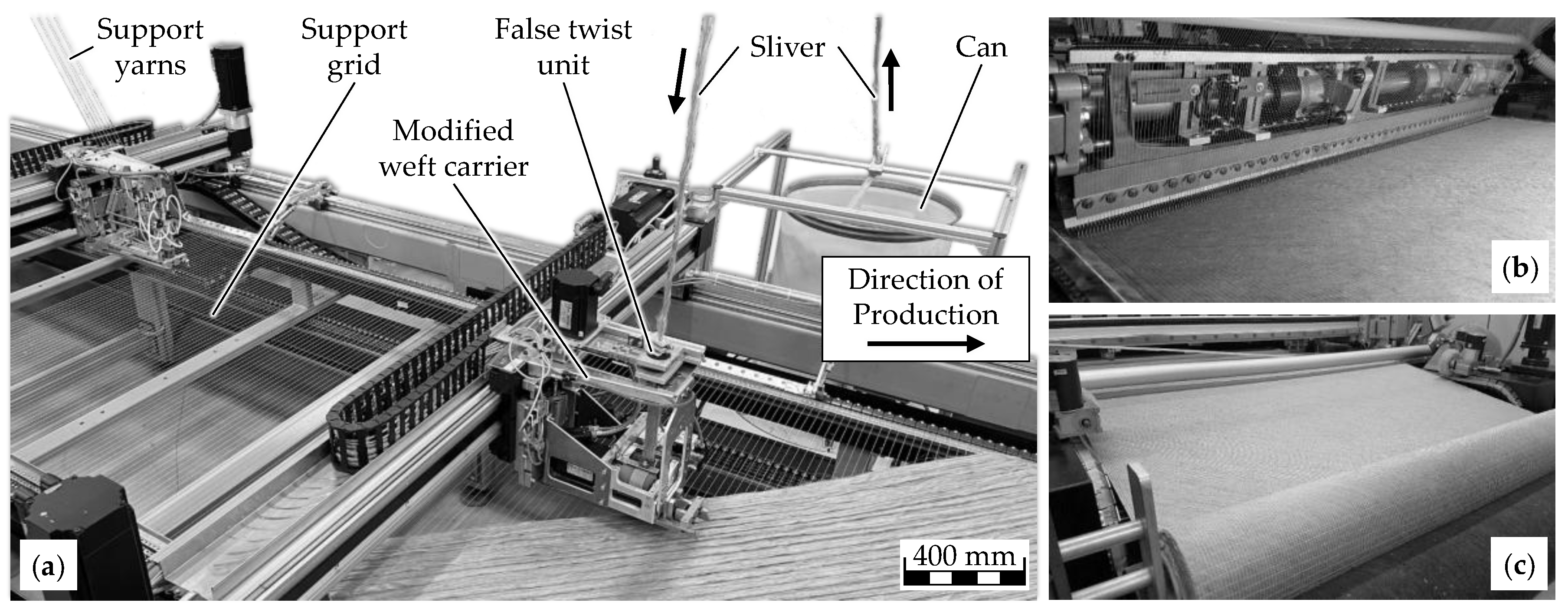
Figure 2.
Procedure for determining the average local fiber orientation in NCF samples using the ImageJ plugin OrientationJ. Adapted from [14].
Figure 2.
Procedure for determining the average local fiber orientation in NCF samples using the ImageJ plugin OrientationJ. Adapted from [14].
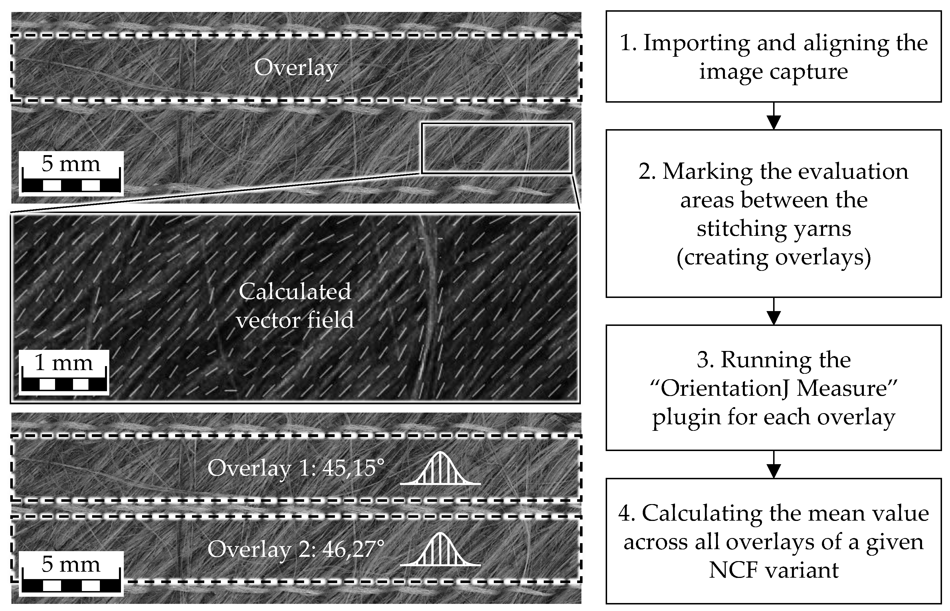
Figure 3.
(a) Tensile stress-strain curves of NCF composites; (b) Detailed view for 0–0.5% strain.
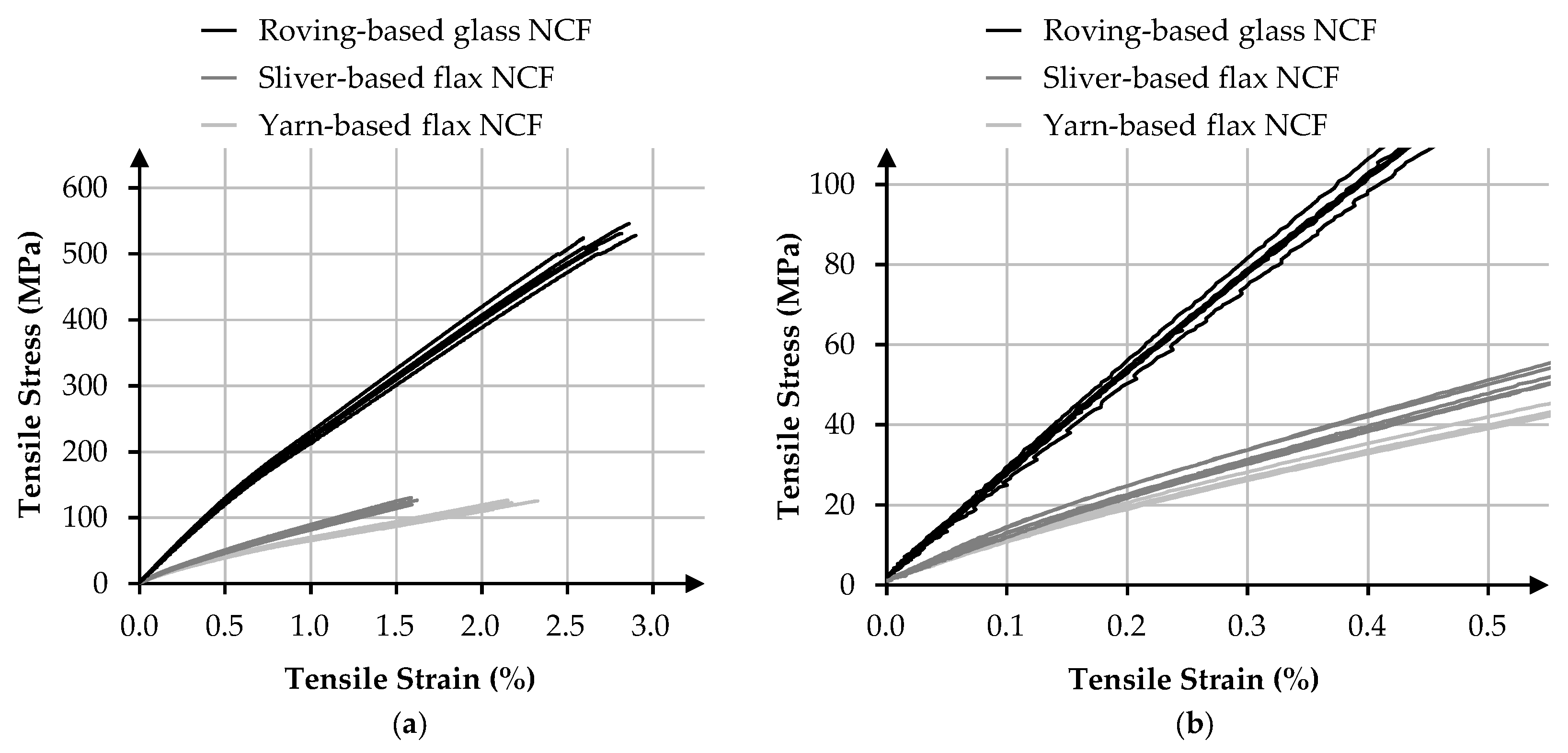

Table 1.
Overview of the investigated NCFs.
| Property | Roving-based glass NCF |
Yarn-based flax NCF |
Sliver-based flax NCF |
|---|---|---|---|
| Reinforcing Fiber | E-glass, ~2.6 g/cm³ | Flax, ~1.4 g/cm³ | Flax, ~1.4 g/cm³ |
| Fiber form | Roving, 300 tex | Yarn, 105 tex | Sliver, 5,000 tex |
| Stitching yarn | text. PES, 76 dtex | text. PES, 76 dtex | text. PES, 76 dtex |
| Stitching pattern | Fringe | Fringe | Fringe |
| Layer configuration | +45°/-45° | +45°/-45° | +45°/-45° |
| Total areal weight | 606 g/m² | 350 g/m² | 395 g/m² |
| Product name | HP-B600E | ampliTex 5008 | - |
| Producer/ distributor |
HP-Textiles GmbH, Germany |
Bcomp Ltd., Switzerland |
ITA of RWTH, Germany |
Table 2.
Overview of modules and their respective functions of the modified NCF machine.
| Module | Function |
|---|---|
| Sliver feeding unit | Continuous, twist-free delivery of flax slivers from a rotating can |
| False-twist unit | Temporary twisting of the slivers for consolidation during feeding |
| Weft carrier | Placement of slivers at ±45° angles onto a supporting polyester grid |
| Stitching unit | Fixation of the layers using polyester stitching yarns |
| Winding unit | Winding of the finished NCF onto rolls |
Table 3.
Specimen dimensions and test setup parameters used for compressive testing.
| Material | Sample thickness (mm) |
Sample width (mm) |
Sample length (mm) |
Support span (mm) |
|---|---|---|---|---|
| Roving-based glass NCF | 1.85 | 15.00 | 55.50 | 37.00 |
| Yarn-based flax NCF | 2.98 | 15.00 | 89.40 | 59.60 |
| Sliver-based flax NCF | 3.55 | 15.00 | 106.50 | 71.00 |
Table 4.
Average local fiber orientation in NCFs. Adapted from [14].
Table 4.
Average local fiber orientation in NCFs. Adapted from [14].
| Material | Average Local Fiber Orientation (°) |
Average Absolute Deviation from 45° (°) |
|---|---|---|
| Roving-based glass NCF | 44.27 ± 2.06 | 1.43 ± 1.64 |
| Sliver-based flax NCF | 43.29 ± 2.36 | 2.05 ± 2.05 |
| Yarn-based flax NCF | 46.45 ± 0.86 | 1.45 ± 0.86 |
Table 5.
Tensile properties of NCF composites. Adapted from [14].
Table 5.
Tensile properties of NCF composites. Adapted from [14].
| Material | Tensile Strength (MPa) | Tensile Modulus (GPa) |
|---|---|---|
| Roving-based glass NCF | 527.38 ± 13.59 | 25.61 ± 2.77 |
| Sliver-based flax NCF | 126.47 ± 3.61 | 10.46 ± 0.37 |
| Yarn-based flax NCF | 118.87 ± 6.30 | 8.26 ± 0.05 |
Table 6.
Compressive properties of NCF composites. Adapted from [14].
Table 6.
Compressive properties of NCF composites. Adapted from [14].
| Material | Compr. Strength (MPa) | Compr. Modulus (GPa) |
|---|---|---|
| Roving-based glass NCF | 437.62 ± 26.31 | 26.98 ± 2.21 |
| Sliver-based flax NCF | 89.64 ± 3.27 | 9.76 ± 0.68 |
| Yarn-based flax NCF | 89.24 ± 1.87 | 8.62 ± 0.51 |
Table 7.
Flexural properties of NCF composites. Adapted from [14].
Table 7.
Flexural properties of NCF composites. Adapted from [14].
| Material | Flexural Strength (MPa) | Flexural Modulus (GPa) |
|---|---|---|
| Roving-based glass NCF | 640.30 ± 7.19 | 13.31 ± 1.40 |
| Sliver-based flax NCF | 148.59 ± 12.01 | 6.58 ± 1.38 |
| Yarn-based flax NCF | 144.19 ± 3.46 | 5.35 ± 0.30 |
Table 8.
Overview of the investigated NCFs. Adapted from [14].
Table 8.
Overview of the investigated NCFs. Adapted from [14].
| Property | Roving-based glass NCF |
Yarn-based flax NCF |
Sliver-based flax NCF |
|---|---|---|---|
| FVC (Vol.-%) | 50,03 | 31,33 | 31,20 |
| Fiber density (g/cm³) | ~2.60 | ~1.40 | ~1.40 |
| Matrix density (g/cm³) | ~1.15 | ~1.15 | ~1.15 |
| Composite density (g/cm³) | 1,88 | 1,23 | 1,23 |
Table 9.
Specific mechanical properties of NCF composites. Adapted from [14].
Table 9.
Specific mechanical properties of NCF composites. Adapted from [14].
| Material | Spec. Tensile Strength (MPa·cm³/g) | Spec. Tensile Modulus (GPa·cm³/g) | Spec. Compr. Strength (MPa·cm³/g) | Spec. Compr. Modulus (GPa·cm³/g) | Spec. Flexural Strength (MPa·cm³/g) | Spec. Flexural Modulus (GPa·cm³/g) |
|---|---|---|---|---|---|---|
| Roving-based glass NCF | 281,20 ± 7,25 | 13,66 ± 0,32 | 233,34 ± 14,03 | 14,39 ± 1,18 | 341,41 ± 3,83 | 7,10 ± 0,75 |
| Sliver-based flax NCF | 102,99 ± 2,94 | 8,52 ± 0,30 | 73,00 ± 2,66 | 7,95 ± 0,55 | 121,00 ± 9,78 | 5,36 ± 1,12 |
| Yarn-based flax NCF |
96,77 ± 5,13 | 6,73 ± 0,04 | 72,65 ± 1,52 | 7,02 ± 0,42 | 117,38 ± 2,82 | 4,36 ± 0,24 |
Disclaimer/Publisher’s Note: The statements, opinions and data contained in all publications are solely those of the individual author(s) and contributor(s) and not of MDPI and/or the editor(s). MDPI and/or the editor(s) disclaim responsibility for any injury to people or property resulting from any ideas, methods, instructions or products referred to in the content. |
© 2025 by the authors. Licensee MDPI, Basel, Switzerland. This article is an open access article distributed under the terms and conditions of the Creative Commons Attribution (CC BY) license (http://creativecommons.org/licenses/by/4.0/).
Copyright: This open access article is published under a Creative Commons CC BY 4.0 license, which permit the free download, distribution, and reuse, provided that the author and preprint are cited in any reuse.


