
Submitted:
21 July 2025
Posted:
22 July 2025
You are already at the latest version
Abstract
Foundation failure is often attributed to unknown site or loading conditions. These failures can be categorized as being the result of inadequate site investigation, design procedure and/or construction techniques. In foundation design, engineers may introduce simplifying assumptions, which may not exist at best, overlooking loading conditions and ignoring certain characteristics of the soil. In additional, due to lack of rational solutions in foundation engineering, designers may use empirical methods given in textbooks and design manuals. Often, these methods have design limitations and range of validity, which are hardly met. The outcome from these categories is manifested in the form of excessive settlement of the foundation elements, reduction of bearing capacity and perhaps catastrophic disasters and loss of lives. While difficulties during site investigation and construction of foundations can be easily overcome by following adequate procedure and construction norms, design procedure remains undefined in some areas. In this paper, some documented design procedures will be examined against the authors’ research results and collected data
Keywords:
hidden conditions
; loads
; failure
; shallow foundations
; deep foundations
; difficult soils
; judgement
; foundation engineering
1. Introduction
The public relies heavily on geotechnical engineers to design safe and economical foundations. Due to the uncertainty and the complex natural of soils, foundation failures may take place causing severe damage to properties and loss of lives (among others, Raikar, 1987; Jin, et al., 1991; Feld and Carper, 1996; Subramanian, 2009; Carretero-Ayuso, 2016; Mushiri et al., 2017; Wang et al., 2017). Foundation failure can be classified under three main categories; these are: inadequate site investigation, inadequate design procedure and inadequate construction techniques. In addition, natural hazards such as earthquakes; hurricanes and environmental changes may upset the design conditions, which may lead to failure (Levy and Salvadori, 2002; Lekkas, 2004; Dos Santos et al., 2017). Nevertheless, designers may have to identify these potentials based on the data collected for the site in question for a given period of time.
Statistically, inadequate site investigations are responsible for about 70% of foundation failures. This category can be avoided by following standard procedures recommended for site investigation. Developers and Government authorities need to be well informed about the value and return of investing in this stage. Inadequate construction techniques cause about 10% of foundation failures, which can be easily avoided by insuring proper supervision. Last but not least, inadequate design procedure, which is the subject of this paper, is responsible for the remaining 20 % of foundation failures (Mulyukov, 1992). Foundation failures due to inadequate design procedure include inadequate or incomplete engineering analysis, the use of inappropriate design theories or the inability to forecast conditions, which may take place during the lifespan of the structure. In such cases, hidden loads and unforeseen conditions may prevail and drastically decrease the factor of safety, or significantly increase the foundation settlements, causing instability and partial or complete failure of the structure.
In courts around the world, disputes related to foundation failures can be found in large numbers. Designers may have to identify the category and to prove that they followed the best and most recent techniques available to design the foundations and present the pertinent data available for the site in question.
In the following sections, typical cases of foundation failure due to inadequate design procedure will be described.
2. Bearing Capacity of Foundations on Homogenious and Layer System
One of the major assumptions used to develop bearing capacity theories is that the soil is homogeneous. Quite often this assumption is not fully comprehended. In reality, ground is made of layers with different strength and mineralogy. Occasionally, ground is made of one type of soil with variable shear strength. It is the designer’s call to treat the ground configuration as a homogeneous soil or as a layer system. In making such decisions, designers may refer to textbooks and design manuals for guidance. Meyerhof (1951), Das (1990), Venkatramriah (1993), and Budhu (2000), amongst others, have suggested that ground may be treated as homogeneous for the purpose of estimating the bearing capacity if the ratio H/B is equal to or greater than one. Where H is the thickness of the upper layer below the footing base and B is the footing width. Meyerhof and Hanna (1978) presented experimental data which contradicts this assumption. Figure 1 presents the experimental results of Meyerhof and Hanna for the case of a strong layer overlying a weak deposit. It can be noted that the soil system behaved as a layer system up to H/B = 5 for strip footings and 2.5 for circular footings. Accordingly, the use of Terzaghi’s theory for estimating the bearing capacity for cases of H/B < 5 may lead to a significant reduction of the bearing capacity and accordingly of the factor of safety and further may lead to catastrophic failure.
The following example illustrates the case described herein:
The case of strip footing on: 1-homogeneous sand, 2-strong sand layer overlying weak deep sand layer 3-strong sand layer overlying weak deep clay layer. In these cases, the ultimate bearing capacity is calculated for values from H = B up to H = 5B), and for the angles of shearing resistance for the upper layer () and for the lower layer (= 0 for clay, and for weak deep sand layer). By taking the width of the foundation B = 5 ft., the depth of the foundation D = 5 ft., c2 = 400 lb/ft2 and lb/ft2. The results obtained are presented in Table 1 and in Figure 2 for the case of , and c2 = 400 lb/ft2.
For the estimation of the ultimate bearing capacity for the case of homogeneous soil, the theory of Terzaghi (1943) was used, and for layered system, the theories of Meyerhof and Hanna (1978) was used as follows:
where: and
- For clay as lower layer,
and
- For loose sand as lower layer,
and
It can be noted from Figure 2 that for the ratio H/B = 2, the bearing capacity of a layered soil (strong sand overlying loose sand) is about 50% less than that for homogeneous soil. This percentage increases up to 85% in the case of strong sand overlying clay. Therefore, for the latter case for example, taking a factor of safety equal to 3, the allowable bearing capacity of the soil considered to be homogeneous is much greater (more than double) than that of the ultimate bearing capacity of the layer system.
It should be made clear herein that the ratio of H/B< 5 is developed for this specific layered system. In other words, this ratio will increase due to the decrease in the shear strength of the lower layer. Hypothetically, this ratio will reach infinity when the shear strength of the lower layer reaches a zero value (Terzaghi’s theory). Furthermore, when the bearing capacity of the layered system reaches that of the homogeneous case, the lower layer will continue to significantly contribute to the settlement of this foundation.
Quite often excessive settlement of the foundation elements is associated with differential settlements among these units. Differential settlement produces additional stresses on the structural elements and eccentricities in the foundation causing structural damage to the building. Differential settlement is regarded as a serious hidden condition in foundation design. It upsets the horizontal levelling floors, the vertical alignment, produces cracks in the walls and crumbles the brickwork of the building.
3. Skin Friction as a Resisting Force or Drag Force on Pile Foundations
While designers are knowledgeable of the theories that predict negative skin friction on pile foundations installed in compressible soil, such as soft to medium clay or soft silt, this often goes unnoticed at the design stage. Negative skin friction may not exist shortly after construction; however, it often manifests itself during the lifespan of the building. This is mainly due to unauthorized direct loading on the surrounding area of the piles, and/or a sudden drop in the water table level due to deep excavation or environmental changes in the neighbouring area. Depending on the relative speed of the soil/pile system, negative skin friction may develop on the upper part of the pile’s shaft, significantly reducing the pile capacity (Figure 3).
In order to demonstrate the role of negative skin friction on pile foundations, the theory developed by Hanna and Sharif (2006) is used to calculate the negative skin friction for piles installed in clay. In this example the effective unit weight of soilγ’ = 8 kN/m3, the surcharge load S = 24 kN/m2, the angle of shearing resistance ϕ = 18o, and the coefficient of friction for pile/clay material β = 0.27. The results are presented in Table 2 and Figure 4.
It can be noted from this Table and Figure 4 that by ignoring the negative skin friction on piles, the bearing capacity is significantly reduced and accordingly the factor of safety. In these cases, the application of bituminous coating or other viscous coatings on the pile’s shaft may significantly reduce the negative skin friction or perhaps eliminate it completely (Hanna and Sharif, 2006).
The pile may experience the presence of both negative and positive skin frictions at the working load level. At the ultimate load, the negative skin friction is diminishing, and the pile’s shaft will be subjected only to positive skin friction. The allowable load capacity should be estimated by the following Equation:
where, Qnf is the negative skin friction for the clay layer.
4. Foundations on Sensitive Clay Subjected to Cyclic Loading
Cyclic loading on foundations built on sensitive clay produces remolding action that facilitates the dissolution of the bonding agencies between particles, which in turn may lead to slippage, excessive settlement, loss of shear strength and often liquefaction.
Based on published research studies in the literature on the subject (Liang and Ma, 1992; Lefebvre and Pfendler, 1996; Miller et al., 2000), it can be reported herein that researchers have made serious efforts to model this complex behaviour. Nevertheless, these models were short of recognizing the pre-consolidation pressure as a major parameter in governing this behaviour and further as the link between the physical and mechanical parameters of sensitive clays. Physical parameters include: natural water content (wc), liquid limit (LL), and plastic limit (PL). The mechanical parameters include the sensitivity number (St), number of cycles (N), cyclic deviator stress (qcyc), pore water pressure (u), axial strain ( ), pre-consolidation pressure ( c) and confining pressure ( 3). In practice, frequently the sensitive behaviour of some types of clay is overlooked during the site investigation stage and often designers may overlook the nature of load application as cyclic.
Hanna and Javed (2006) examined the role of the physical and mechanical parameters, which govern the shear strength of sensitive (Champlain) clay, obtained from the city of Rigaud, Quebec (Canada), subjected to cycling loading. They reported that for a given sensitivity number (St), the shear strength of the clay and the safety factor decreases due to an increase of the number of cycles (N). Figure 5 presents the factor of safety versus the number of cyclic. The factor of safety was defined as the ratio of the shear strength at a given cycle over the shear strength at failure. It can be noted from this figure that the undrained period is the most critical period for these foundations, and the factor of safety decreases rapidly due to the increase of the number of cyclic.
It should be mentioned herein that driving piles in sensitive clay by hammering may generate load cycling of the soil around the pile’s shaft during driving, reducing its shear strength. In this case, if skin friction is a major source of resistance, the use of bored piles is recommended.
Hanna and Javed14 proposed a design procedure to establish a safe zone for the undrained and drained periods, within which a combination of the cyclic deviator stress and the number of cycles for a given soil/loading/site conditions can achieve a quasi-elastic resilient state without reaching failure (Figure 6). This procedure can be adopted to examine the conditions of existing foundations built on sensitive clays at any time during their lifespan.
5. Foundations on Collapsible Soils
Due to the increase of land development all over the world, the need to deal with difficult soils has become essential. The most well known difficult or problematic soils are collapsible soils, sensitive clays, swelling soils and peat.
Quite often, especially in arid areas, soil may experience excessive settlement (a significant reduction in volume, Figure 7) and possess low bearing capacity when it becomes wet. This type of soil is known as “collapsible soil”. Evstatiev (1988) reported the spread of one type of collapsible soil, known as loess, in many countries, such as, the former Soviet Union, China, Africa (e.g. Egypt), the United States, Brazil, Australia, and many countries in Eastern Europe. Adequate testing methods have to be used for the identification of collapsible soils (Ayadat and Hanna, 2007).
Often collapsible soil is unnoticed during the site investigation stage, and accordingly, problems for the supported structure during its lifespan are expected to include: large non-uniform settlements of the shallow foundations, uncalculated negative skin friction on pile foundation and accordingly, the drag load during its lifespan, which may drastically decrease the factor of safety of the foundation.
Special consideration for the design and construction of foundations on/in collapsible soils should be taken. Several treatment methods were suggested to include:
- Replacing collapsible soil with crushed stones or with treated soils (Ali, 2015).
- Avoid the collapsible soil layer by installing pile foundation.
- Use precast piles or bored piles with caissons to avoid the use of excessive amount of concrete.
- Stone columns encapsulated in geofabrics (Khabbazian et al., 2015; Nazari and Ghazavi, 2014; Al-Obaidy, 2018), and
- Chemical treatment of the collapsible soil is also suggested (Efferson et al., 2015; Khodabandeh et al., 2023)
The sources of wetting from urbanization activities should be well identified and localized. Hidden conditions may arise from the uncontrolled access of water to the soil foundation. Wetting can be from surface sources (pipelines, uncontrolled drainage of surface water from construction, or discharge of industrial effluents or irrigation), or from the change in the groundwater table, which causes full collapse and many accompanied problems.
6. Foundation on Contaminated Soils
Due to rapid industrialization, large quantities of industrial disposal are being discharged in the surrounding areas causing contamination of soils, altering their natural properties. For any possible application and design of structures on a contaminated site, knowledge in the geotechnical properties and behaviour of contaminated soil is required.
Hidden conditions in such cases may arise from the difficulty to characterize contaminated materials. Waste or contaminated fills exhibit heterogeneous and isotropic material that are difficult to characterize. The contamination of soil alters some of the material’s physical properties including higher unit weight due to reduced friction between grains, decreasing value for peak shear stress as saturation increases, decreasing angle of shearing resistance, increasing vertical settlement, and changing the coefficient of water permeability, etc. The bearing capacity calculation for shallow foundations is very sensitive to the values assumed for the shear strength of soil, namely the angle of shearing resistance (ϕ) and cohesion (c). Therefore, as previously indicated, careful consideration must be given to the values selected to define the contaminated soil shear strength (Figure 8). Furthermore, the occurrence of differential settlement is even more critical than total settlement, and is primarily inevitable due to the heterogeneity of solid wastes (Figure 9).
To illustrate the influence of contamination on the calculated bearing capacity and settlement of shallow foundations, the results of an illustrative example for contaminated sand are presented in Table 3. In this example the bearing capacity and settlement ratios (contaminated/clean) of strip shallow foundation with width, B =1.2 m, embedded in a homogeneous sand to a depth D = 1.5 m was estimated. The data used for the calculation, for clean and contaminated sand (light and heavy oil), was deduced from Figure 8 and Figure 9. It is quite clear from Table 3 that contamination considerably affects the bearing capacity up to a reduction of 60% and increases the settlement by a factor of 2. This example clearly shows how an improper characterization of contaminated materials creates the potential for hidden sources of additional distress.
7. The Determination of the Angle of Soil Shear Strength
In determining the bearing capacity of foundations, the crucial choice is the value of the angle of shearing resistance, ϕ. Based on experimental investigations Hanna and Massoud (1981) found that the angles of shearing resistance deduced from the direct shear tests is different from those obtained from triaxial tests and notably from the plane-strain tests (Figure 10).
Based on these results, it can be confirmed that estimating the bearing capacity of circular footings, cofferdams or in general any isolated foundations, based on the results of either the shear box or the triaxial test, normally does not represent any harmful conditions for security (stability) and economy. However, for embankments, earth dams, tunnels, strip foundations, long retaining walls, and excavations, where the plane strain test results should be used, this consideration may lead to hidden uneconomical conditions by including extra expenses. Furthermore, for certain retaining structures subjected to passive earth pressure (e.g. plate strip anchors), this consideration places the structures in the unsafe side which may cause severe troubles and damages.
An illustrative example was given in Table 4 in order to illustrate the influence of the angle of shearing resistance on the calculated bearing capacity of strip foundation. In this example the bearing capacity of strip shallow foundation with width, B =1.2 m, embedded in a homogeneous sand to a depth D = 1.5 m was calculated. It is clear from this Table that the plane angle of shearing resistance overestimates the values of the bearing capacity (qult) by a factor of 40 to 60 % compared to those obtained by triaxial. Another example can be considered treating the case of a smooth backed vertical wall of 6 m high retaining a sand fill with a bulk unit weight of 18 kN/m2 and ϕ = 35o (shear box). The top of the fill is level with the top of the wall and is horizontal. The soil surface carries a uniformly distributed load of 45 kN/m2. The total active thrust per linear meter of wall is 160.97 KN. But actually, using the result of the plane strain test (ϕ = 40o), this value drops to 128.85 kN. Consequently, in both examples, larger dimensions of the structure elements are designed than it is practically (actually) required.
Quite often in a small size laboratory, the shear box test and at a lesser extend the triaxial test are used to determine these parameters regardless of the field condition. To overcome the unavailability of the triaxial apparatus and the plane-strain apparatus in the average soil mechanics laboratory, beside the technical difficulties and the cost involved in performing this type of shear tests, Hanna et al. (1987) proposed relationships between the angle of shearing resistances of the sand deduced from plane-strain, conventional triaxial compression, and direct shear box test results.
8. Conclusions
With the growth of modern urban communities, more sites are being developed for construction. Nevertheless, designers continued to proceed with the classic site investigation program, overlooking the existence of weaker soils below, fail to identify difficult soils and to consider all possible loading conditions. The cost of correcting these errors is greatly exceeds the original expenditure of the foundation, these beside possible property damages and the loss of lives. If designers, building officials, and owners recognize these problems in advance, it will be possible to avoid or reduce the losses.
Acknowledgment
The financial support received from the Academic of Scientific Research & Technology of Egypt, Natural Science and Engineering Research Council of Canada (NSERC) and Concordia University are acknowledged.
References
- Ali, N.A. Performance of partially replaced collapsible soil – Field study. Alexandria Engineering Journal, 2015, 54, 527–532. [CrossRef]
- Al-Obaidy, N. (2018). “Treatment of collapsible soil using encased stone columns.” Ph.D. thesis, School of Civil Engineering, College of Engineering and Physical Sciences, Univ. of Birmingham.
- Al-Sanad, Hasan A.; Eid, Walid K.; Ismael, N.F. Geotechnical properties of oil-contaminated Kuwaiti sand. Journal of Geotechnical Engineering 1995, 121, 407-412. [CrossRef]
- Ayadat and Hanna Identification of Collapsible Soils Using the Fall Cone Apparatus. Geotechnical Testing Journal (ASTM) 2007. [CrossRef]
- Budhu, M. (2000). Soil Mechanics & Foundations. John Wiley & Sons, Inc, New York.
- Carretero-Ayuso, M.J., Moreno-Cansado, A., Cuerda-Correa, E.M. (2016). Research and analysis on recurring anomalies in foundations and structures. Journal of Performance of Constructed Facilities, 30(3), 04015037. [CrossRef]
- Das, B. (1990). Principle of foundation Engineering. Brooks/Cole.
- Dos Santos, B.R., Pinheiro, R.V., Arroyo, F.N., de Almeida, D.H., Christoforo, A.L., & Lahr, F.A.R. (2017). Cracks Studies Case of Buildings in Sinop City-Brazil, International Journal of Materials Engineering, 7(6): 101-110.
- Efferson, I., Rogers, C., Evststiev, D., and Karastanev, D., 2015. Improvement of collapsible loess in Eastern Europe. In Ground improvement case histories: compaction, grouting and geosynthetics (pp. 215-261). Oxford: Butterworth-Heinemann. . [CrossRef]
- Evstatiev, D. (1988). Loess improvement methods. Engineering Geology, Vol. 25, pp. 341 – 366.
- Feld, J., and Carper, K.L. (1996), Construction Failure, 2nd Edition, Wiley Inter-science, New York, 528pp.
- Hanna, A.M. and Hoque (2007). Coupled Consolidation Model for Negative Skin Friction on Piles in Clay Layers. International Journal for Numerical and Analytical Methods in Geomechanics.
- Hanna, A.M. and Javid, K. (2006). Foundations on Sensitive Clay Subjected to Cyclic Loading. Journal of Geotechnical and Environmental Engineering.
- Hanna, A.M., and Massoud, N (1981). Interlocking of Granular Materials in Two and Three-dimensional Shear Failure. Proc. of the 8th Canadian Congress of Applied Mechanics [CANCAM81], Moncton, and N.B.
- Hanna, A.M., Massoud, N. and Youssef, H. (1987). Prediction of plane strain angle of shearing resistance from direct shear test results.
- Hanna, A. and Sharif, A. (2006). Drag Force on Single Piles in Clay Subjected to Surcharge Loading. International Journal of Geomechanics, ASCE, 93. [CrossRef]
- Indraratna, B., Balasubramaniam., A.S., Phamvan , P. and Wong, Y.K.(1992), Development of negative skin friction on driven piles in soft Bangkok clay, Canadian Geotechnical Journal, 29, pp.393 – 404. [CrossRef]
- Jin, J.S., M. Ayub and F. Liu (1991) “Investigation of November 19, 1990, Excavation Collapse at 14th and H Streets, N.W. Washington, D.C.”, U.S. Department of Labor, Occupational Safety and Health Administration, Washington, D.C., 109 pp.
- Khabbazian, M., V.N. Kaliakin, and C. Meehan. 2015. “Column supported embankments with geosynthetic encased columns: Validity of the unit cell concept.” Geotech. Geol. Eng. 33 (425): 425–442. [CrossRef]
- Khodabandeh, M.A., Nagy, G. and Török, Á., 2023. Stabilization of collapsible soils with nanomaterials, fibers, polymers, industrial waste, and microbes: Current trends. Construction and Building Materials, 368(130463.). [CrossRef]
- Lefebvre, G., and Pfendler, P. (1996). Strain Rate and Pre-Shear Effects in Cyclic Resistance of Soft Clay. Journal of Geotechnical Engineering, ASCE, 122 (1), 21-26. [CrossRef]
- Lekkas, E. L. (2004). Earthquake geodynamics: seismic case studies. WIT.
- Levy, M., and Salvadori, M. (2002) Why Buildings Fall Down: How Structures Fail, W.W. Norton & Co., New York, 336pp.
- Liang, R.Y., and Ma, F. (1992). Anisotropic plasticity Model for Undrained Cyclic Behavior of Clays. Journal of Geotechnical Engineering, 1992, 118 (2), 229-243. [CrossRef]
- Meyerhof, G. (1951). The ultimate bearing capacity of foundations. Geotechnique, 2(4), 301-331.
- Meyerhof, G.G. and Hanna, A.M. (1978). Ultimate Bearing Capacity of Foundations on Layered Soils under Inclined Load. Canadian Geotechnical journal, 15, 565-572. [CrossRef]
- Miller. G.A., The, S.Y., Li, D., and Zaman, M.M. (2000). Cyclic Shear Strength of Soft Railroad Subgrade. Journal of Geotechnical and Geoenvironmental Engineering, ASCE, 126 (2), 139-147. [CrossRef]
- Mulyukov, É.I. (1992). Classification of causes of failure of bases and foundations. Soil Mechanics and Foundation Engineering, 29(3), 90-93. [CrossRef]
- Mushiri, T., Shumba, S., Matora, T., Mhizha, S., Tumbare, M., Taaka, D., & Musiwa, K. (2017). Investigating Structural Cracks for Infrastructure: Case Study of Anonymous Hospital, in Zimbabwe. EAI International Conference for Research, Innovation and Development for Africa, 432.
- Nazari Afshar, J., and M. Ghazavi (2014). “Experimental studies on bearing capacity of geosynthetic reinforced stone columns.” Arabian J. Sci. Eng. 39 (3): 1559–1571. [CrossRef]
- Raikar, R.N. (1987) Learning from Failures: Deficiencies in Design, Construction and Service, R&D Centre, Structwel Designers & Consultants, Mumbai, 423 pp.
- Subramanian, N. (2009) Rare Foundation Failure of a Building in Shanghai, China, New Building Materials & Construction World (NBM & CW), Aug., pp.100-105.
- Terzaghi, K. (1943) Theoretical Soil Mechanics. John Wiley, New York.
- Venkatramriah, C. (1993). Geotechnical Engineering. John Wiley & Sons, New York.
- Wang, W. D., Q. Li, Y. Hu, J.W. Shi, and C.W.W. Ng (2017), “Field Investigation of Collapse of a 13-Story High-Rise Residential Building in Shanghai”, Journal of Performance of Constructed Facilities, ASCE, Vol. 31, No.4, Aug.
Figure 1.
Experimental results: bearing capacity of footings on a strong sand layer overlying deep loose sand deposit, (a) strip footings, (b) circular footings (After Meyerhof and Hanna, 1978).
Figure 1.
Experimental results: bearing capacity of footings on a strong sand layer overlying deep loose sand deposit, (a) strip footings, (b) circular footings (After Meyerhof and Hanna, 1978).
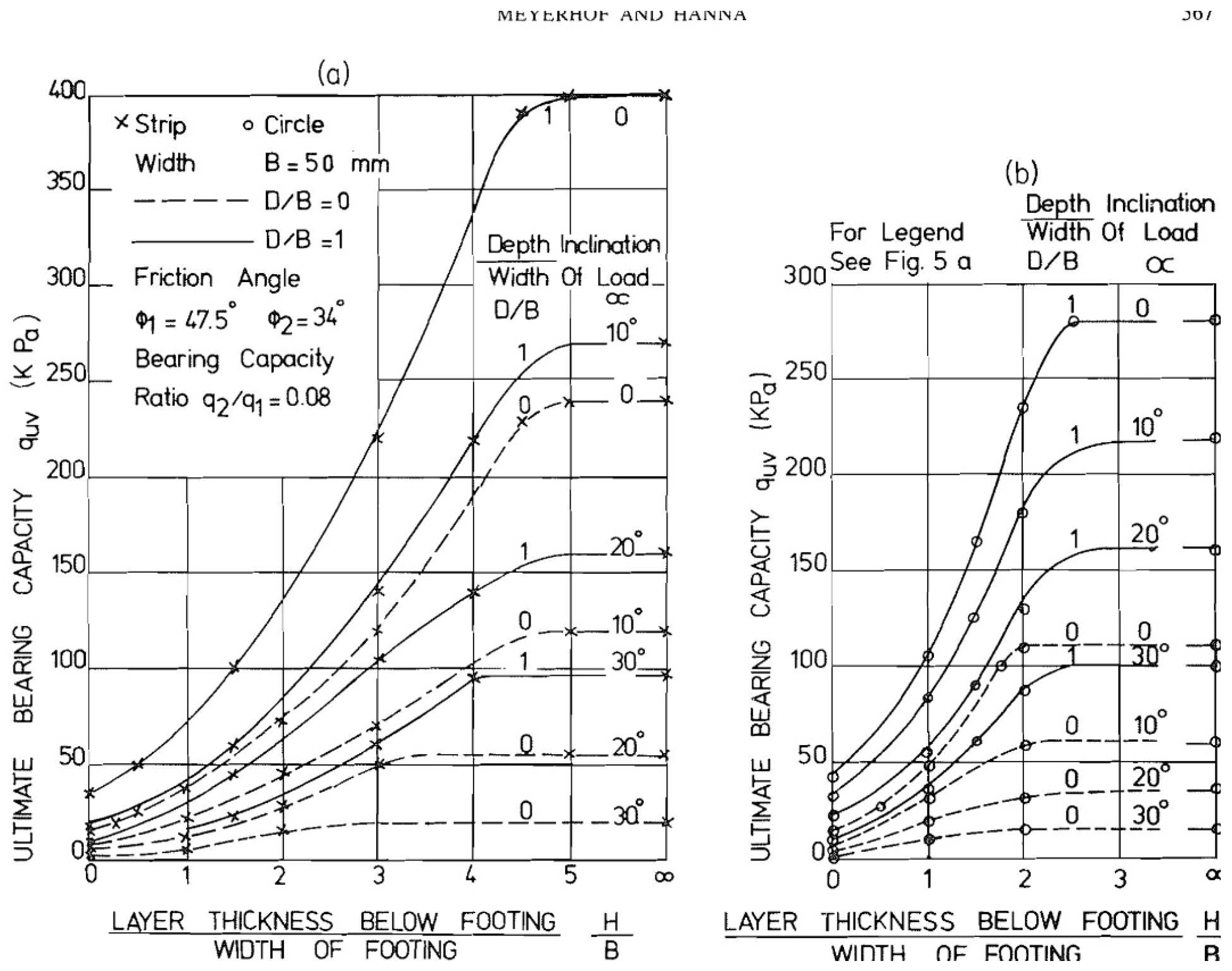
Figure 2.
Bearing capacity of shallow foundation on different soil condition versus H/B (, and c2 = 400 lb/ft2).
Figure 2.
Bearing capacity of shallow foundation on different soil condition versus H/B (, and c2 = 400 lb/ft2).
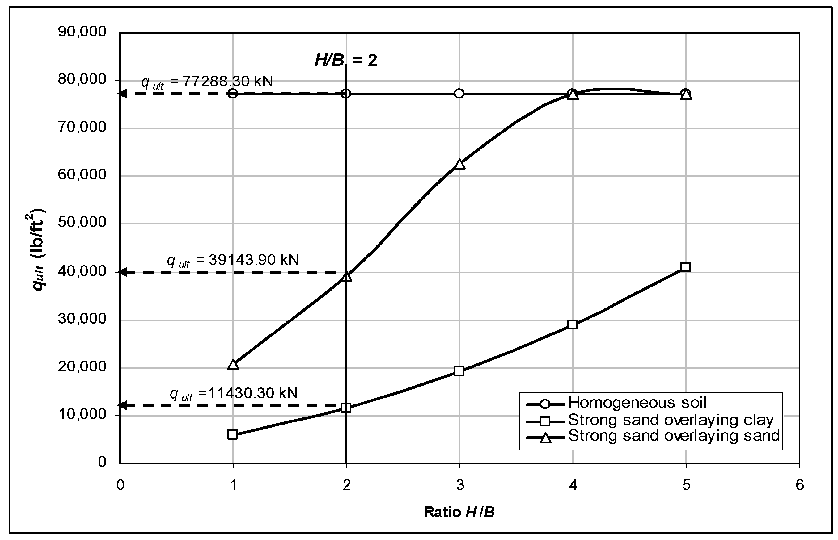
Figure 3.
Predicted (Hanna and Hoque, 2007) and field measured (Indraratna et al, 1992) values of the Negative and positive skin friction on the pile’s shaft.
Figure 3.
Predicted (Hanna and Hoque, 2007) and field measured (Indraratna et al, 1992) values of the Negative and positive skin friction on the pile’s shaft.
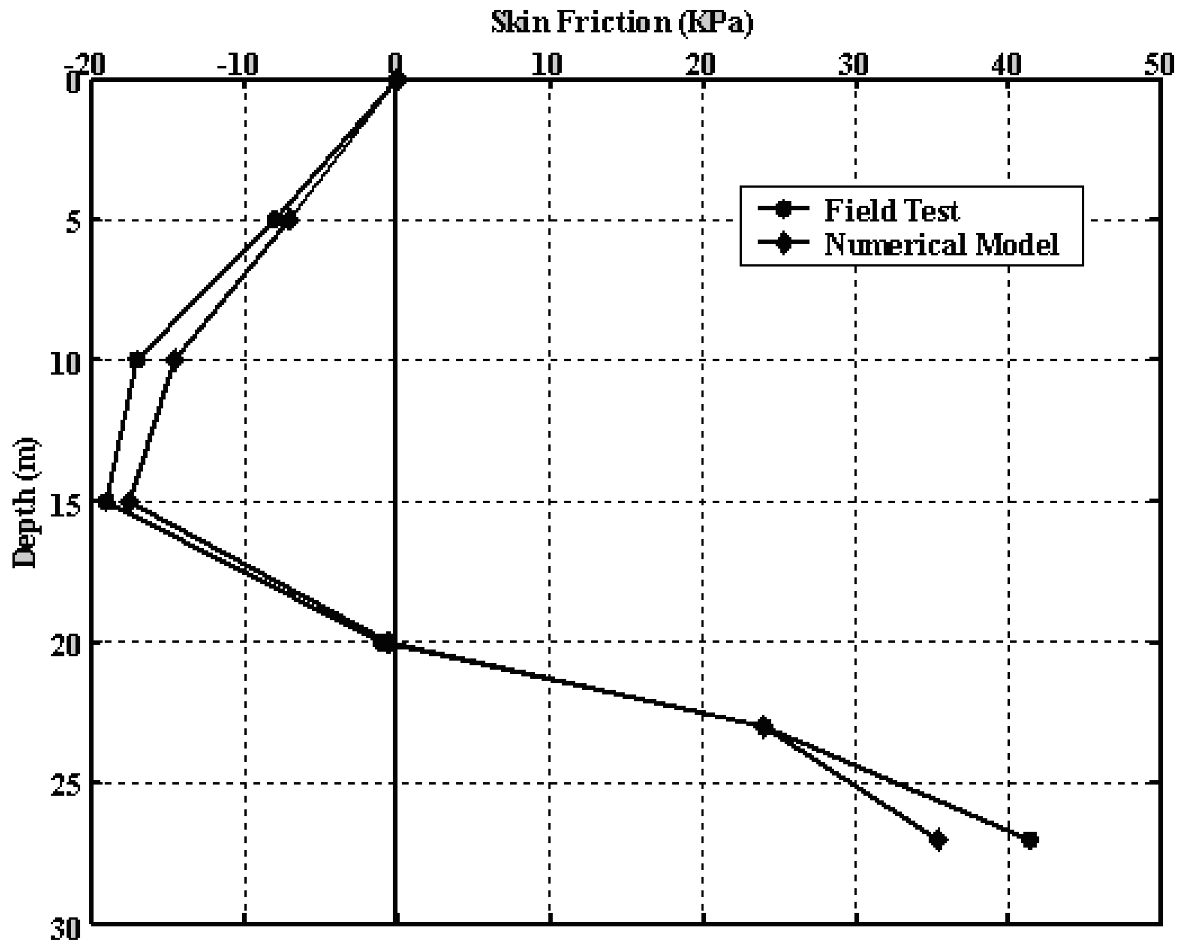
Figure 4.
Allowable bearing capacity versus pile length.
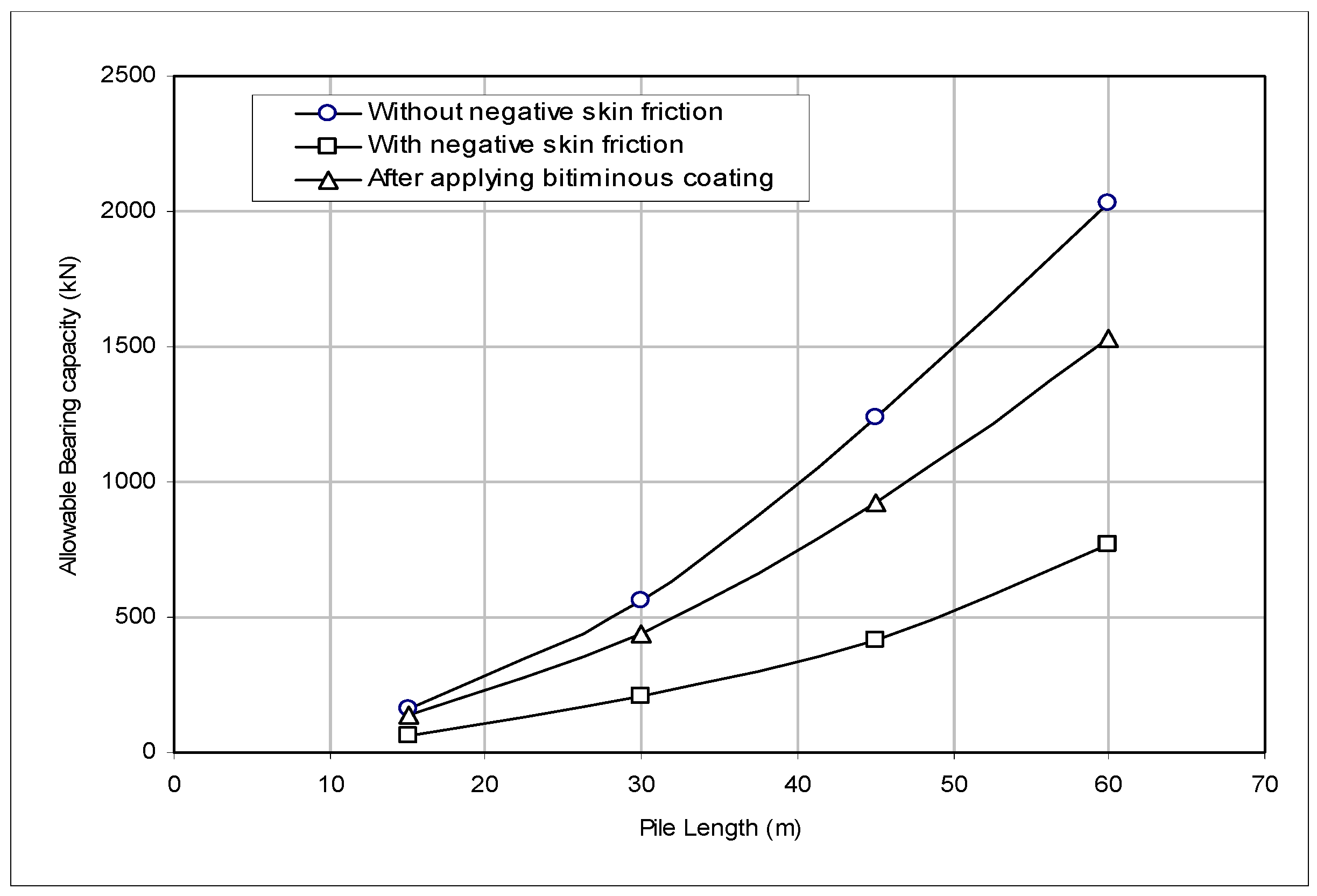
Figure 5.
Number of cycles (N) versus factor of safety (F) (After Hanna and Javid, 2006).
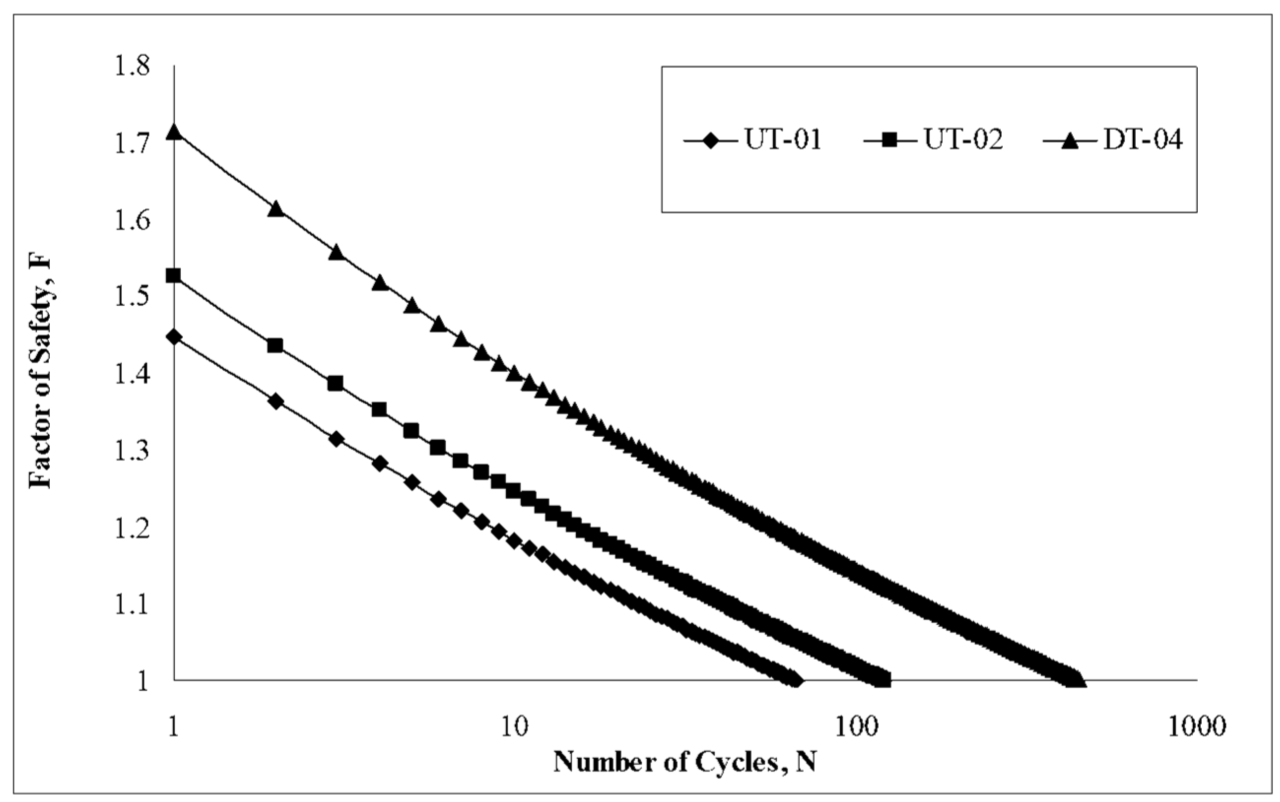
Figure 6.
Schematic sketch - Safe zones for foundation on sensitive clay (Hanna and Javed, 2006).
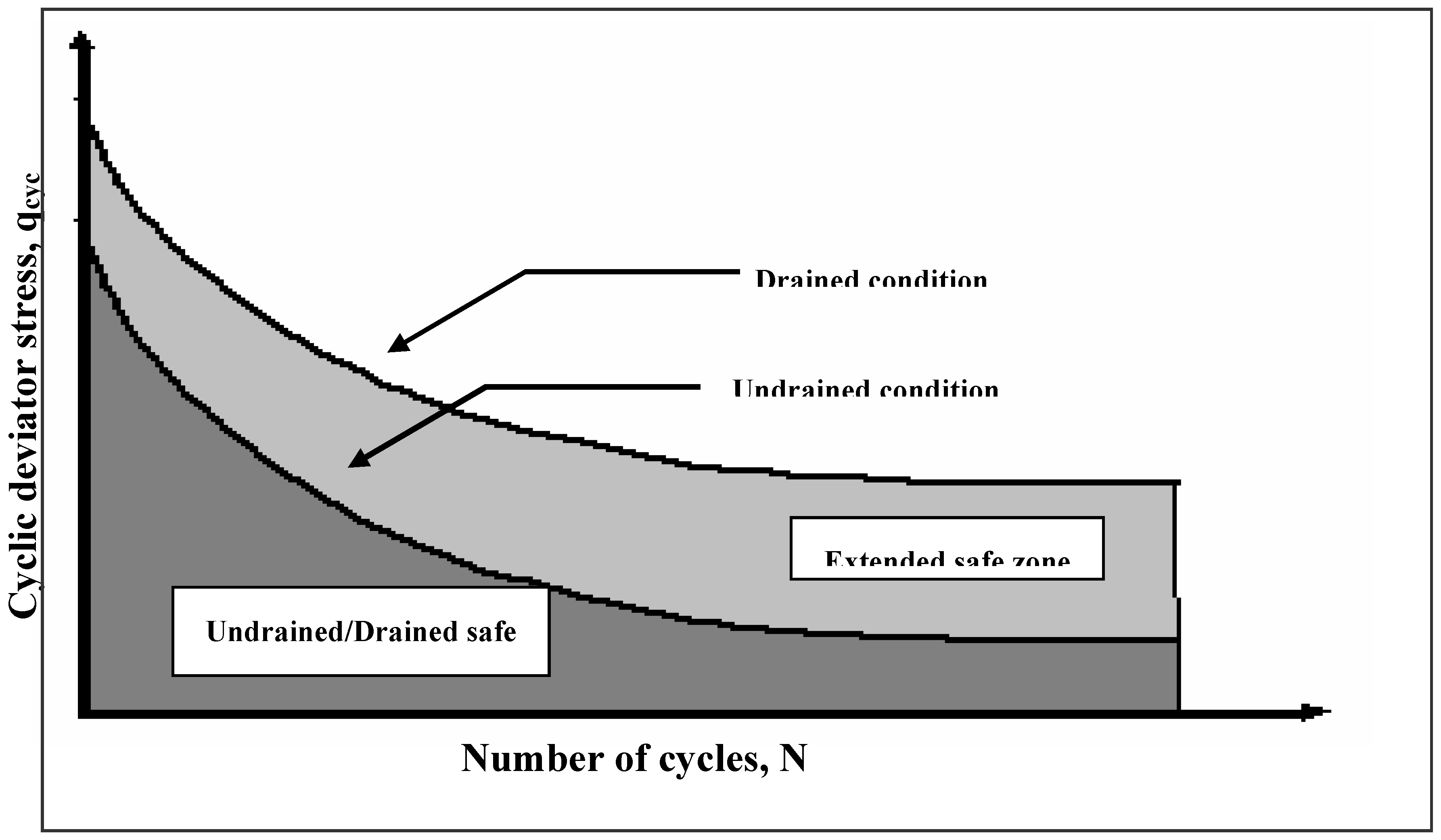
Figure 7.
Typical oedometric curves of collapse deformation against load for the different soils tested (After Ayadat and Hanna, 2007).
Figure 7.
Typical oedometric curves of collapse deformation against load for the different soils tested (After Ayadat and Hanna, 2007).
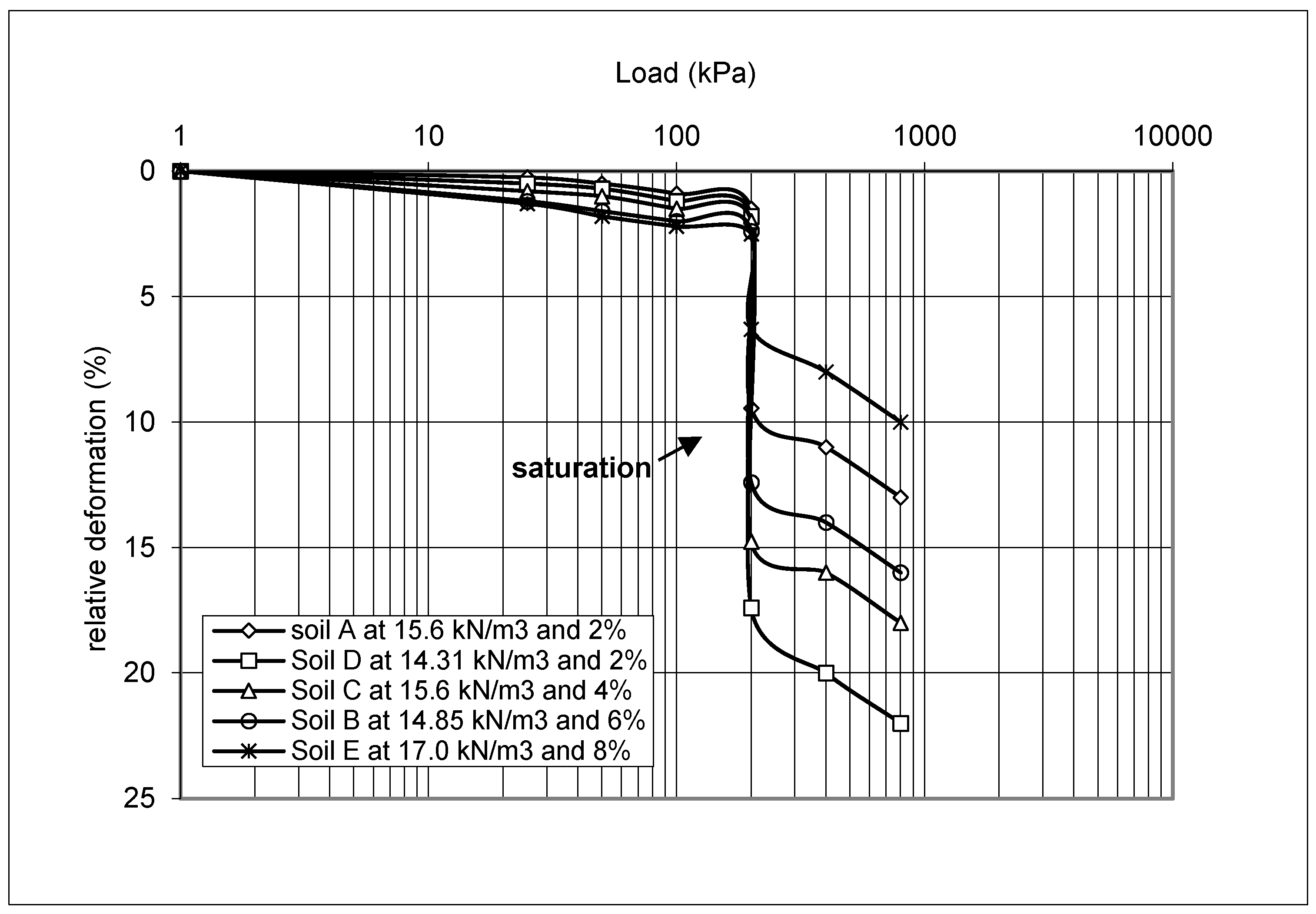
Figure 8.
Angle of shearing resistance versus relative density for heavy crude oil and light gas oil. (After Al-Sanad et al., 1995).
Figure 8.
Angle of shearing resistance versus relative density for heavy crude oil and light gas oil. (After Al-Sanad et al., 1995).
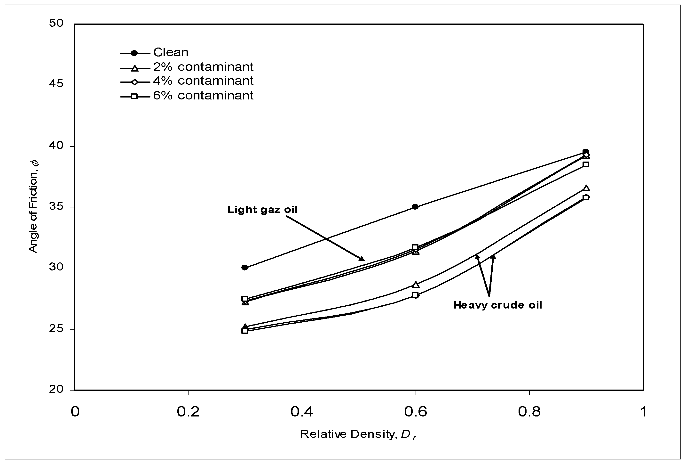
Figure 9.
e-logP plots for natural and contaminated samples (After Al-Sanad et al., 1995).
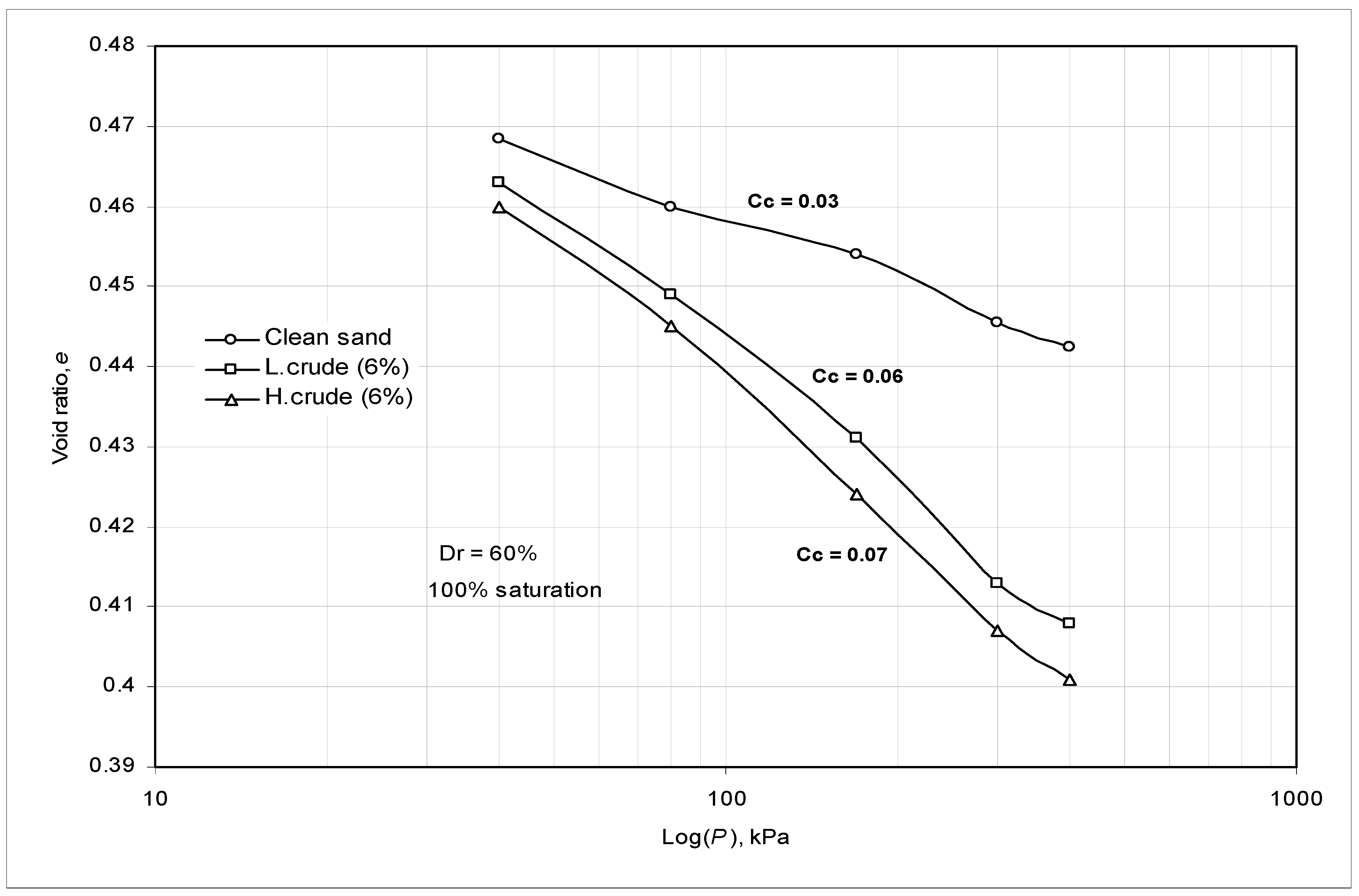
Figure 10.
Angle of shearing resistance in plane strain, triaxial compression and direct shear tests versus porosity: Sand S1, N or σ3 = 344 kPa (After Hanna and Massoud, 1981) .
Figure 10.
Angle of shearing resistance in plane strain, triaxial compression and direct shear tests versus porosity: Sand S1, N or σ3 = 344 kPa (After Hanna and Massoud, 1981) .
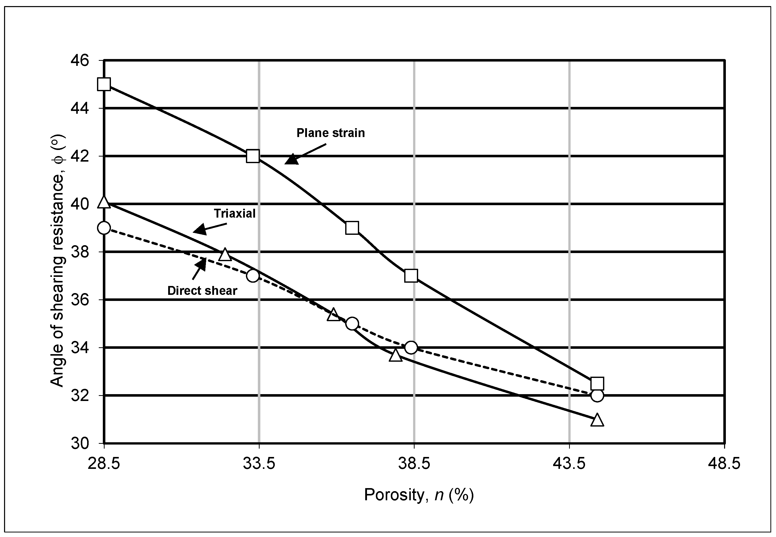

Table 1.
Values of the ultimate bearing capacity of homogeneous and layered soils.
| H (ft.) | H/B |
qult (lb/ft2) (Homogeneous soil) |
qult (lb/ft2) (strong sand overlying softclay c2 = 400 lb/ft2) |
qu (lb/ft2) (strong sand overlying loose sand having) |
|
| 30 | 5 | 1 | 19,240.00 | 6,082.73 | 16,724.5 |
| 30 | 10 | 2 | 19,240.00 | 11,710.61 | 19,240.0 |
| 30 | 15 | 3 | 19,240.00 | 19,240.00 | 19,240.0 |
| 30 | 20 | 4 | 19,240.00 | 19,240.00 | 19,240.0 |
| 30 | 25 | 5 | 19,240.00 | 19,240.00 | 19,240.0 |
| 35 | 5 | 1 | 37,254.75 | 6,118.67 | 18,695.5 |
| 35 | 10 | 2 | 37,254.75 | 11,806.47 | 34,074.9 |
| 35 | 15 | 3 | 37,254.75 | 19,769.37 | 37,254.8 |
| 35 | 20 | 4 | 37,254.75 | 30,007.40 | 37,254.8 |
| 35 | 25 | 5 | 37,254.75 | 37,254.75 | 37,254.8 |
| 40 | 5 | 1 | 77,288.25 | 5,977.61 | 20,596.3 |
| 40 | 10 | 2 | 77,288.25 | 11,430.30 | 39,143.9 |
| 40 | 15 | 3 | 77,288.25 | 19,064.07 | 62,598.9 |
| 40 | 20 | 4 | 77,288.25 | 28,878.91 | 77,288.3 |
| 40 | 25 | 5 | 77,288.25 | 40,874.82 | 77,288.3 |
| 45 | 5 | 1 | 175,994.00 | 8,554.27 | 27,076.1 |
| 45 | 10 | 2 | 175,994.00 | 18,301.38 | 56,423.3 |
| 45 | 15 | 3 | 175,994.00 | 31,947.33 | 94,997.7 |
| 45 | 20 | 4 | 175,994.00 | 49,492.13 | 142,799.4 |
| 45 | 25 | 5 | 175,994.00 | 70,935.78 | 175,994.0 |
| 50 | 5 | 1 | 455,334.75 | 13,160.14 | 39,951.3 |
| 50 | 10 | 2 | 455,334.75 | 30,583.71 | 90,757.2 |
| 50 | 15 | 3 | 455,334.75 | 54,976.71 | 159,373.9 |
| 50 | 20 | 4 | 455,334.75 | 86,339.14 | 245,801.3 |
| 50 | 25 | 5 | 455,334.75 | 124,670.99 | 350,039.5 |
Table 2.
Allowable Bearing Capacity of plies with/without negative skin friction.
|
Length of Pile L (m) |
Diameter of Pile D (m) |
Allowable bearing capacity Pa (kN) |
||
| Without Negative Skin Friction | With Negative Skin Friction | After bituminous coating | ||
| 15 | 0.60 | 164.00 | 58.00 | 139.00 |
| 30 | 0.60 | 563.00 | 206.00 | 440.00 |
| 45 | 0.60 | 1238.00 | 417.00 | 920.00 |
| 60 | 0.60 | 2027.00 | 772.00 | 1534.00 |
Table 3.
Calculated bearing capacity and settlement ratios for shallow strip foundation on contaminated sand.
Table 3.
Calculated bearing capacity and settlement ratios for shallow strip foundation on contaminated sand.
| Relative density, Dr | Angle of shearing resistance of sand ,ϕ (o) |
Compression index (Cc) void ratio (e) |
Bearing Capacity Ratio qcontaminated/ qclean |
Settlement ratio (Scontaminated/Sclean) at P = 170 kPa |
||||||
| Clean | Light oil | Heavy oil | Clean | Light oil | Heavy oil | Light oil | Heavy oil | Light oil | Heavy oil | |
| 0.3 | 30 |
27.5 | 24.8 | 0.738 | 0.54 | |||||
|
0.6 |
35 |
31.5 |
27.7 |
0.03 0.45 |
0.06 0.43 |
0.07 0.42 |
0.63 |
0.40 |
2.03 |
2.40 |
|
0.9 |
39.5 |
38.5 |
35.7 |
0.861 |
0.586 |
|||||
Table 4.
Calculated bearing capacity for shallow strip foundation on sand.
|
Type of soil |
N or σ3(kPa) |
Measured (Hanna and Massoud, 1981) | Bearing capacity,qult (KN/m) | |||||
| Rd (%) | ϕds | ϕT | ϕps | Direct shear |
Triaxial test |
Plane test |
||
|
Sand (Well graded/Angular Sand, Gs = 2.64) |
172 |
47.5 60 85 |
36.0 37.6 39.8 |
36.0 37.1 40.0 |
39.5 41.5 44.0 |
1654.01 2158.42 2851.99 |
1654.01 2000.79 2915.3 |
2757.42 4123.13 6136.63 |
|
344 |
47.5 60 85 |
33.7 35.4 37.9 |
34.3 35.2 38.0 |
37.5 39.3 43.2 |
1161.39 1464.85 2253.01 |
1243.24 1401.8 2284.53 |
2126.9 2694.37 5492.31 |
|
Disclaimer/Publisher’s Note: The statements, opinions and data contained in all publications are solely those of the individual author(s) and contributor(s) and not of MDPI and/or the editor(s). MDPI and/or the editor(s) disclaim responsibility for any injury to people or property resulting from any ideas, methods, instructions or products referred to in the content. |
© 2025 by the authors. Licensee MDPI, Basel, Switzerland. This article is an open access article distributed under the terms and conditions of the Creative Commons Attribution (CC BY) license (http://creativecommons.org/licenses/by/4.0/).
Copyright: This open access article is published under a Creative Commons CC BY 4.0 license, which permit the free download, distribution, and reuse, provided that the author and preprint are cited in any reuse.


