Submitted:
04 July 2025
Posted:
07 July 2025
You are already at the latest version
Abstract
Long-distance pressurized water pipelines are prone to water hammer effects during valve opening and closing, which poses a threat to the safe operation of the pipeline. This paper focuses on a water conveyance project from a certain reservoir, addressing the challenges of water hammer protection in long-distance and high-drop water supply networks. The characteristic line method is used to construct a simulation model of the hydraulic transition process. After designing a tiered pressure relief pool, the impact of different valve opening and closing times on water hammer in the water conveyance system is calculated. Based on this, a "pressure relief pool + air valve" collaborative protection strategy is proposed. The research results indicate that implementing a two-stage pressure relief pool can effectively control the overpressure along the water conveyance system. Additionally, using air valves in conjunction with valve opening and closing can effectively improve the internal water pressure distribution along the water conveyance system without affecting its response speed.
Keywords:
water hammer
; numerical simulation
; pressurized water pipeline
; high drop
1. Introduction
As the problem of uneven spatial and temporal distribution of global water resources is becoming more and more serious, long-distance water conveyance project is an important technical means to satisfy social production. Long-distance pressurized water transmission system with high drop, due to the high terrain drop, usually up to several hundred meters, compared with the low drop gravity flow pressurized water transmission system, the transition process of this water transmission system is more dangerous and complex. The system in the valve operation process generated by the transient flow water hammer phenomenon, often leading to rapid changes in the internal pressure of the pipeline, resulting in the separation of the water column, bridging, pipe burst. Therefore, the study of water hammer effect in water distribution system and the optimization of protection strategy has been an important topic in the field of water distribution engineering. At present, scholars have carried out a large number of studies on water hammer protection measures for long-distance pressurized water transmission systems.Li Jiangyun et al[1]The water hammer propagation characteristics of long-distance water transmission systems are analyzed, and the combined application of air valves, regulator towers and other protective measures is proposed;Li Jiang et al [2] verified the effect of end valve closing time on water hammer pressure by numerical simulation, and suggested to use 300s to close the valve at a uniform speed; Lin Xiaozhi et al [3], as an example, constructed a numerical model of water hammer pressure and evaluated the effect of different protective measures for a water diversion and transfer project in Yunnan Province; and Xu Dawei et al [4], described in detail the experience of the design of the alteration and expansion of the long-distance and large-height difference water transmission pipeline. Pei Shuangbao [5], as an example of Shanxi Province Yumenkou water lifting east expansion project, for the complexity of the third section of its gravity flow, according to the basic principles of water hammer calculation, the establishment of the overpressure relief valve, the air tank mathematical model, the use of numerical simulation, respectively, simulate the air valve, the air valve and the overpressure relief valve, the air valve and the air tank joint protection of the working conditions of the change in the pressure of the water hammer; Cai Fulin et al.[6] established a mathematical model of water transmission system transition process calculation based on transient flow analysis of the eigenline method, and investigated the water hammer problem when the long-distance multi-branch pressurized water transmission system, which contains gravity flow transmission pipeline and pumping station pressurized lifting pipeline, is opened; Chen Minghui et al.[7] investigated the local water hammer characteristics of the intermediate bulge pipeline section and its protection against water hammer with the arrangement of the hump-type pipeline long water transmission system. Elucidated the one-way regulator tower on the hump type long distance water pipeline protection mechanism, and deduced the one-way regulator tower set the height of the approximate analytical formula; LiPengYu, etc. [8] to an actual long distance gravity flow water transmission project as an example, simulate the end of the valve transition process, analyze the water hammer pressure of the system under the different shut-off rules, verify the gravity flow shut-off valve water hammer characteristics and theoretical formulas, and on the basis of the proposed sub-phase On the basis of this, the selection method of valve closing rate and folding point opening is proposed. Ma Yiyang[9]took a long-distance gravity flow water transfer project in Shanxi Province as an example, established a hydraulic transient calculation model, and based on the model developed an optimization program of valve shut-off curve and valve arrangement scheme using genetic algorithm. The results show that the multi-stage valve shut-off program is significantly better than the one-stage valve shut-off program; in addition, Dang Zhiliang[10] explored the optimization method of the number of decompression tank stages and the arrangement location.Bian Shaokang et al. [11] established a calculation model for the hydraulic transition process of a certain project based on the Porter method, analyzed the valve closing law without protective measures, compared the protective effects of traditional ordinary air valves and three-acting air valves, and discussed the influence of the three-acting air valve combined with the two-stage valve closing scheme on the valve closing water hammer. Guo Weiqi et al. [12] used computer simulation to simulate multiple protective measures such as linear valve closing, two-stage valve closing, and combined overpressure relief valves. Zhang Yousheng et al. [13], based on the overall layout plan of the pipeline network and the characteristics of water usage, adopted a hydraulic mathematical model and water hammer calculation method to analyze the hydraulic transition process of the water transmission pipeline under different operating conditions, and simulated the influence of valve opening and closing at different times on the pressure and water hammer changes along the pipeline. Huang Wei et al. [14], taking actual engineering as an example, conducted numerical simulations of pump stop water hammer under four water hammer protection schemes: air valve protection, combined protection of air valve and end valve, combined protection of air valve, end valve and overflow pipe, and combined protection of air valve and air valve pressure regulating chamber. Sun Yiming et al. [15] established a water hammer calculation model using PIPENET and conducted a protection study on the water hammer phenomenon that occurs in pressurized water supply pipelines when pumps stop due to accidents through a combined protection method of multi-functional hydraulic control valves, gas injection micro-discharge valves, and air tanks. Zhang Dongjun et al. [16] conducted a water HAMMER simulation analysis of a long-distance water transmission project based on the Bentley HAMMER V8i water hammer calculation software. By setting different working states, they carried out calculation and analysis around the maximum pressure value, the reverse rotation of the water pump and the vacuum degree of the pipeline to explore the technical measures for protecting against water hammer. A water hammer elimination scheme combining "multi-functional water hammer pump control valve + air valve + pressure-holding and pressure-relief valve" was derived. Shi Lin et al. [17] proposed a water hammer protection scheme combining an air tank and an outlet overflow pool for some water supply projects with special terrain conditions in this paper, and established a mathematical model of the outlet overflow pool. Wang Shunsheng et al. [18] studied the water hammer protection effect when the airbag air tank is used in combination with the multi-functional water pump control valve and air valve, as well as the influence of the tank volume and the preset pressure of the airbag on the water hammer protection effect. The research results show that installing airbag-type air tanks in high-head and medium-flow water conveyance projects can achieve a good water hammer protection effect. Zhou Tianchi et al. [19] used the hydraulic transition process simulation calculation software Hysimcity for modeling and calculation analysis to carry out the water hammer protection design of the entire water transmission system. It was finally determined to install an overpressure relief valve with a diameter of 1 meter in front of the Linping, Renhe, Hongpan and Tangxi water plants, as well as a combined water hammer protection scheme of one-section linear closure of the valves of each water plant. This effectively solved the water hammer problem of the multi-user gravity flow water supply system. Tan Zhen et al. [20] established a finite volume method Godunov scheme hydraulic transient mathematical model for the combined pressure-unpressure flow and inverted siphonic pressurized flow in a long-distance water transmission system, and conducted a simulation study on the operational hydraulic characteristics. Bian Shaokang et al. [21] established a calculation model for the hydraulic transition process of a certain actual project based on the Baud property method. The valve closing rule without protective measures was studied. The protective effects of traditional ordinary air valves and three-action air valves were compared. The sensitivity analysis of the air valve diameter parameters was conducted. The influence of two-stage valve closing + air valve combined protection on valve closing water hammer was investigated. Zhu Sheng [22], taking the pre-built gravity flow water transmission pipeline in a mountainous county in the southeast as an example, selected the reservoir water level, pipeline flow rate and valve closing point as variables, obtained 12 operating conditions, simulated the hydraulic transition process of these conditions under various valve closing durations, and analyzed the influence of three variables on valve closing water hammer. Song Naishuo et al. [23], through the application of large drop gravity water conveyance in the water supply project of Mengga Town, Mangshi City, Yunnan Province, introduced the pressure water hammer protection measures for pressure reduction and energy dissipation, the layout of exhaust valves and precautions in the design of large drop gravity flow pipeline water conveyance.
Li Pengyu et al. [24], taking a certain actual long-distance gravity flow water transmission project as an example, simulated the end valve closing transition process, analyzed the water hammer pressure of the system under different valve closing rules, verified the water hammer characteristics and theoretical calculation formulas of gravity flow valve closing, and on this basis, proposed a selection method for phased valve closing rates and breakpoint opening degrees. Tong Baolin et al. [25], aiming at the selection problem of the flow characteristics of the end flow regulating valve in a gravity flow system under large amplitude flow, based on one-dimensional water hammer theory, adopted numerical simulation methods and combined with engineering examples, A comparative study is conducted on three types of flow characteristics, namely linear type, parabolic type and equal percentage type, from three aspects: the influence of the flow characteristics of the flow regulating valve on the steady-state operation opening degree, the determination of the most unfavorable flow condition of water hammer when the flow regulating valve is closed, and the influence of the flow characteristics of the flow regulating valve on the water hammer when the valve is closed. Gu Yuanhao et al. [26] established the corresponding water hammer calculation model using KY PIPE2022 software. Through numerical simulation, they explored the entire process of water hammer hydraulic transition in the water delivery system when the pump was stopped, and discussed the influence laws of different closing procedures of two-stage slow-closing check valves and different arrangements of airbag air tanks on the water hammer protection effect. Zhang Yong et al. [27], using Bentley Hammer software, established a mathematical model of the dual-pump parallel unit in the pumping station water delivery system, and studied the influence of pipeline optimization before and after different valve closing schemes in two stages on the most unfavorable water hammer parameters such as water hammer pressure and unit speed. Wang Zhiyang et al. [28] adopted the characteristic line method and utilized water hammer numerical simulation software to establish a basic model for water hammer calculation in long-distance water transmission pipelines. The water hammer phenomenon and its variation laws under four working conditions of the stable operation state, adjusted operation state, operation state of the maintenance and pipe cutting section and pipe burst of the water conveyance pipeline system from Huangchi Gou water distribution hub to Banqiao Water outlet of the north main line of the second phase of the Han Water to Wei Water diversion project were analyzed and studied. Dou Pinxin et al. [29] pointed out that for underwater water supply pipelines, conventional waterproof hammer measures could not be adopted. Instead of the air valve, a single-outlet style waterproof hammer air valve and a pressure regulating pipe were used to meet the waterproof hammer requirements of the pipeline. The calculation results of the closed valve water hammer, open valve water hammer and flow regulation water hammer of the water supply pipeline under different working conditions were analyzed and studied by the characteristic line method. Qu Ningling [30] Taking the water supply project of County A as an example, based on the basic principle of water Hammer and the characteristic line method, the model calculation and analysis of the water hammer condition when the pump stops in this project were carried out by using the unique model system of the Bently Hammer software. The simulation results show that after the pump group of the three-stage series pumping station in County A stops due to an accident, multiple pipelines are facing the hazards of overpressure and negative pressure. Based on the simulation results, targeted water hammer protection design is carried out for the water transmission system.
At present, the research on the water hammer protection measures of long-distance pipeline water transmission system focuses on the control strategy of opening and closing of low-drop valves and the application of different water hammer protection measures, and there are fewer research studies on the water hammer protection of long-distance high-drop water transmission system when it is opened and closed.
This paper takes a reservoir water transmission project as the research object, for the water hammer protection problem of long-distance high drop water transmission network, adopts the characteristic line method to construct the hydraulic transition process simulation model, and calculates the hydraulic transition process of long-distance high drop pressurized water transmission system when it is opened and closed. Through comparative analysis, the impact of different valve opening and closing control strategies on water hammer is investigated, and the synergistic protection strategy of “multi-stage decompression tank + air valve” is proposed. It provides theoretical basis and engineering reference for similar projects.
2. Water Hammer Models and Methods
2.1. Water Hammer Models and Methods
The basic equation of water hammer derived from the momentum theorem and the continuity theorem of water flow is given by
formula:V——flow velocity in the pipe, positive downstream; H——pressure head; x——distance, with the pipe inlet as the origin, positive downstream;t——time;a、g——water hammer wave velocity and gravitational acceleration;d、α——pipe diameter and longitudinal slope angle;
f——Darcy's coefficient of friction, dimensionless.
2.2. Computational Mathematical Modeling of Transition Processes in Pressurized Water Distribution Systems
2.2.1. Characteristic Line Method for Calculation of Transition Processes in Pressurized Pipelines
As shown in Figure 1 for the characteristic grid nodes of pressurized pipeline, the characteristic compatibility equation for water hammer calculation of pressurized pipeline system is
formula:CP、BP、Cm、,Bm——known quantities at moment t-△t;Hpi、Qpi——unknown quantities at moment t.
2.2.2. Inlet Node
The inlet node is shown in Figure 2, and the control equations describing the parameters of this node are
formula:HR——Reservoir levels.
1.2.3. Outlet Nodes of the Water Distribution System
As shown in Figure 3 for the outlet node of the water delivery system, the control equation describing the parameters of the node can be obtained as
2.2.4. Boundary Conditions for Control Valves
3. Project Cases
3.1. Project Overview
A long-distance high drop pressurized water transfer project, elevation range 3832~4230m, the total length of the water pipeline 22.521 km is a typical long-distance high drop water transfer system. The design flow rate of the main pipe is 0.921~0.985 m³/s; the design flow rate of No.1, 2, 3, 4 and 5 sub-pipes are 0.013, 0.012, 0.017, 0.014 and 0.008 m³/s. There are 2 decompression tanks set up on the main pipe, which are located in K2+385.00 and K7+575.00 respectively, and the regulating valves of the gravity flow line are all arranged in the front end of the decompression tank and the most part of the pipeline. The regulating valves of gravity flow pipeline are arranged at the front end of the decompression pool and the most end of the pipeline.
3.2. Water Hammer Protection Analysis
Gravity flow pipeline, the longer the pipeline in front of the regulating valve, the shorter the valve closing time, the greater the water hammer pressure generated by the closing valve, the greater the impact of water hammer on the pipeline. If the regulating valve is close to the head of the system, due to the water pressure difference between the upstream and downstream sides of the regulating valve, the water distribution system downstream of the regulating valve may appear unpressurized flow conditions at low flow rates, resulting in water supply disorders; especially when the system is shut down, some of the high level of the arrangement of the pipeline section may appear empty pipe conditions. The regulating valve of the gravity flow pipeline of this project is arranged at the end of each segment, and the operation of the pipeline is mainly controlled by the operation of the regulating valve. Therefore, the transition process characteristics of this project's water pipeline network depend on the operation mode of each regulating valve and the operating flow rate of the system. This project belongs to the long-distance pipeline design engineering, according to the requirements of CECS193-2005 “Urban Water Supply Long Distance Water Transmission Pipeline (Drainage) Pipeline Engineering Technical Specification” and GB50013-2018 “Outdoor Water Supply Design Standard” are as follows: during the transition process of various working conditions, there should be no water column breakage in any part of the pipeline; The design of water hammer protection measures should ensure that the maximum water hammer pressure (maximum internal water pressure) of the water pipeline does not exceed 1.3~1.5 times the maximum working pressure; no negative pressure along the pipeline.
Each branch pipe in the network is a reserved branch pipe with a design flow rate less than 2% of the flow rate of the trunk pipe, and the length of the reserved branch pipe is relatively short, without considering the impact of water hammer at the end of the branch pipe when the valve is closed. Trunk pipe in accordance with the two graded decompression pool (1 # decompression pool / 2 # decompression pool) will be divided into three sections of the trunk pipe, the first section: the starting point of the trunk pipe (water tower inlet) ~ 1 # decompression pool, the second section: 1 # decompression pool ~ 2 # decompression pool, the third section: 2 # decompression pool ~ the end of the trunk pipe. As the decompression pool blocks water hammer propagation, the three segments need to be analyzed one by one. According to previous engineering experience, the opening and closing time of the valve is an important factor affecting water hammer. Therefore, when optimizing the opening and closing methods of the water transmission system, it should be considered from both the opening and closing time and the protection strategy. For the regulating valves, all the regulating valves are opened and closed in a unified way to avoid the pressure shock caused by different opening and closing times of the pressure reducing pool overflow and pipeline pressure and no pressure conditions alternately; calculations to analyze the maximum and minimum internal water pressure in the water pipeline network under different scenarios in order to determine the optimal valve control strategy.
This paper adopts the decompression tank and air valve as additional water hammer protection measures. The decompression tank is arranged in front of the over-pressure part of the pipeline to ensure the safety of the pipeline and block the transmission of water hammer waves; the air valve is mainly arranged in the pipeline at the local high point, the long straight pipeline, the inflection point of the pipeline slope change, the pipeline diameter change, pipeline valves and other accessories. The use of decompression tank + air valve synergistic protection strategy joint valve opening and closing program.
3.3. Multi-Stage Pressure Reducing Tank with Submerged Regulator Valve Design
Decompression pool structure in Figure 5: decompression pool using cast-in-place reinforced concrete box structure, the top of the ventilation pipe to achieve air pressure balance, the pool to maintain the free liquid level conditions. Its core energy dissipation mechanism is reflected in two aspects: (1) structural features level, inverted orifice structure design so that the high-pressure jet through the submerged multi-orifice regulator valve to form a vertical downstream flow; (2) energy dissipation level, high-speed water through the orifice jet section, and the bottom of the pool baffle impact collision, and then along the wall of the pool to form a three-dimensional turbulence of the shear flow state. The device can effectively eliminate the free head of the pipeline (1 # decompression pool to reduce 160m, 2 # decompression pool to reduce 150m), and its impedance mutation characteristics of the upstream and downstream water hammer wave to produce a phase difference, in line with the principle of superposition of the reflection of the water hammer wave propagation. Compared with the traditional pressure regulator tower, the decompression pool system has the advantage of decoupling boundary conditions, especially suitable for high drop terrain water transmission system pressure zoning control.
Submerged multi-orifice regulator valve installation schematic in Figure 6: Submerged multi-orifice regulator valve is a kind of fluid control device with both energy dissipation and flow control functions. Its working principle is that the pressure water through the nozzle to form a high-speed jet, and in the energy dissipation pool through the water flow collision to achieve energy dissipation. The valve drives the axial displacement of the outer cylinder by power to change the working number of jet holes in the inner cylinder, so as to realize the precise adjustment of the flow rate. This type of regulator valve has the following technical advantages:①excellent anti-cavitation performance, in the high pressure difference conditions and large flow range can be stable operation, and will not produce vibration phenomenon;②the valve opening and flow characteristics of the linear relationship between the valve can achieve accurate flow regulation, and has a wide range of adjustment;③reasonable structural design, service life of up to 30 years or more, and low maintenance costs; ④small operating torque, can use electric, hydraulic and other types of drive, can be used. It can be driven by electric, hydraulic and other driving methods, and has good adaptability to the working conditions;⑤It has a wide range of energy dissipation and pressure reduction, and can meet the needs of different working conditions.
4. Results
4.1. Over-Current Capacity Analysis of Water Pipelines (Steady State Operating Conditions)
In the normal water transmission process, considering the normal operation of the pipeline regulating valves throughout the line, the pipeline line the whole line of the roughness of 0.012, constant flow calculation and analysis of the water pipeline network along the main line and some of the branches of the pressure pipe head distribution is shown in Figure 7, the dead water level operation, the trunk and the branch pipe pressure pipe headline higher than the pipeline center line throughout the whole process, indicating that the system to meet the requirements of the self-flow of water transmission. The design of the water transmission pipe network is reasonable, and the flow distribution matches well with the terrain.
4.2. Optimization Analysis of Opening and Closing Rules of Control Valves (Transient Operating Conditions)
Developed different control programs, the opening and closing time of different sections of the valve and valve control strategy under the water pressure in the water pipeline network to calculate the control program and calculation results are shown in the following Table 1-6.
From the calculation results in Table 1, it can be seen that in the first section, the water pipeline end regulating valve 60s shutdown: maximum pressure 221m (65% over the limit), minimum pressure -1m (negative pressure risk); 120s shutdown: maximum pressure 153m (in line with the specification), the minimum pressure of 1.04m (lower than the safety threshold); add protective measures 120s shutdown: maximum internal water pressure and minimum internal water pressure near step Optimization. The minimum internal water pressure along the pipeline is 2.04m water column, which occurs at K7+575.02~K7+586.65. 120s shutdown time is selected, and water hammer protection measures are added along the pipeline to take into account both safety and operational efficiency.
From the calculation results in Table 2, it can be seen that in the second section, the front-end regulating valve of the 2# pressure reducing pool is closed for 30s: maximum pressure 305m (98% over the limit), minimum pressure -10m (vaporization of the water body); closed for 60s: maximum pressure 208m (35% over the limit), minimum pressure -1m (negative pressure); closed for 120s + air valve: maximum pressure 176.48m, minimum pressure 2.05m ( safe operation). Conclusion: The closing time needs to be ≥120s, and with the air valve to make up air.
From the calculation results in Table 3, it can be seen that in the first section, the regulating valve at the front end of the #1 pressure reducing pool is closed for 30s: maximum pressure 254m (23% over the limit), minimum pressure 0m (critical risk); closed for 60s: maximum pressure 199m (in accordance with the specification), minimum pressure 50.4m (no need for protective measures); closed for 120s: maximum pressure 170.51m, minimum pressure 50.4m ( Safe operation). Conclusion: 120s closing time is adopted without considering water hammer protective measures.
From the calculation results in Table 4, it can be seen that in the third section, the water pipeline end regulating valve 60s open: minimum pressure -0.04m (negative pressure risk), manual intervention is required. 120s open: minimum pressure -0.02m (still does not meet the norms); 180s open + air valve: minimum pressure 2.29m appeared in the K7+575.02~K7+596.65. maximum pressure 102m (safe operation). Conclusion: 180s opening time is adopted and combined with air valve replenishment to ensure smooth transition of pressure.
From the calculation results in Table 5, it can be seen that in the second section, 2# pressure reducing pool front-end regulating valve 60s open: minimum pressure -0.82m (negative pressure), maximum pressure 153.39m (in line with the specification); 120s open: minimum pressure -0.38m (still does not meet the specification); 180s open + air valve: minimum pressure of 2.29m, maximum pressure of 153.39m (safe operation). Conclusion: opening time needs to be ≥180s to avoid the risk of negative pressure.
Calculation results from Table 6 can be seen in the first section, 1 # pressure reducing pool front regulating valve 30s open: minimum pressure 3.11m, maximum pressure 154.58m (in line with the specification); 60s open: minimum pressure 3.11m, maximum pressure 154.58m (more efficient), appeared in D0 +110 (the first section of the canal). Conclusion: choose 60s opening time, without considering the water hammer protection measures can take into account the efficiency and safety.
4.3. Air Valve Water Hammer Protection
In the shutdown control program A2, B3, C3; open control program D3, E3, F2 based on the addition of air valves as an additional water hammer protection measures, the use of air valves combined with the valve to open the water hammer protection program for calculation and analysis. After analysis of the proposed installation of 32 air valves along the pipeline network, the specific installation location and the diameter of the air valve is shown in Table 7, calculated to be the third section of the section, the second section, the first section of the maximum pressure of the water inside the regulator valve closure, respectively, 152.27m, 176.48m, 170.51m, respectively, are located in the end of the pipeline regulating valves (valves before the valve), 2 # decompression pool front regulating valves (valves before the valve), 1 # decompression pool front Regulation valve (in front of the valve); minimum internal water pressure at the time of closure is 2.04m, 2.05m, 50.4m, respectively, located in K7+575.02~K7+586.65, K2+385.00~K2+443.39, D0+110 (head of the canal section). The maximum internal water pressure when opening the regulating valve of the third section, second section and first section were 102.68m, 153.39m and 154.58m, respectively, which appeared in the regulating valve at the end of the trunk pipe (in front of the valve), the regulating valve at the front of the #2 pressure reducing pool (in front of the valve), and the regulating valve at the front of the #1 pressure reducing pool (in front of the valve); and the minimum internal water pressure when opening were 2.00m, 2.29m and 50.4m, respectively, which were Located at K7+575.02~K7+596.65, K2+385~K2+395.51, D0+110 (head of canal section). The minimum internal water pressure of each section increased significantly compared with the program without air valve: when the regulating valve was closed, the minimum internal water pressure in the third section increased by 2.04 m, and the minimum internal water pressure in the second section increased by 0.99 m; when the regulating valve was opened, the minimum internal water pressure in the third section increased by 1.95 m, and the minimum internal water pressure in the second section increased by 2.65 m. The influence of the air valve on the maximum internal pressure in the distribution system is small, and the influence on the minimum internal water pressure is small, and the influence on the maximum internal pressure is small, and the influence on the minimum internal pressure is small. air valve on the maximum internal water pressure of the water distribution system is relatively small, and the increase of the minimum internal water pressure is more obvious.
Figure 8 for the closing control program A2, B3 before and after the installation of air valves in each section of the regulating valve upstream of the pressure pipe head with time curve, Figure 9 for the opening control program D3, E3 before and after the installation of air valves in each section of the regulating valve upstream of the pressure pipe head with time curve. After the installation of air valve regulating valve upstream of the pressure pipe head due to valve opening and closing fluctuations caused by a significant reduction and more quickly stabilized. The head line of the smallest pressure measuring pipe rises significantly after the installation of the air valve. The small negative pressure zone at the end of the pipeline is improved, and the negative pressure of the water transmission system increases significantly. In addition, the head fluctuation along the pressure measuring pipe is also smaller after the installation of the air valve.
5. Conclusions
5.1. Over-Current Capacity Analysis of Water Pipelines (Steady State Operating Conditions)
Even when the reservoir is operating at dead level, the entire length of the system trunk line, as well as the #1 sub-pipe, #2 sub-pipe, #3 sub-pipe, #4 sub-pipe, and #5 sub-pipe meet the requirements for self-flowing water conveyance with a certain margin.
5.2 Regulating Valve Opening and Closing Rules
In the shut-off valve operation, extend the closing time can effectively reduce the maximum internal water pressure, increase the minimum internal water pressure, to a certain extent, can avoid the production of water flow breaks in the bridging. In the dry pipe for valve shutdown operation, if a single valve operation, will cause different decompression pool caused by different degrees of overflow loss, decompression pool volume is not enough to replenish the downstream water, air into the pipeline occurs with or without pressure alternating conditions and empty pipe conditions. At the same time, start to close the regulating valve in front of 1# pressure reducing pool, the regulating valve in front of 2# pressure reducing pool, and the regulating valve at the end of the trunk pipe, when the regulating valve in front of 1# pressure reducing pool closes in a straight line at 120s, when the regulating valve in front of 2# pressure reducing pool closes in a straight line at 120s, and the regulating valve at the end of the trunk pipe closes in a straight line at 120s.
Valve operation in the dry pipe, in the regulating valve using different opening control program can be smooth and fast to achieve the design flow; but if a single valve operation, will also cause different decompression tanks caused by different degrees of overflow loss, decompression tanks will not be enough to replenish the downstream water, air into the pipeline to occur with or without pressure alternating conditions and empty pipe conditions. In the valve operation along the dry pipe 1 # decompression pool in front of the regulating valve, 2 # decompression pool in front of the regulating valve, the end of the dry pipe regulating valve open at the same time, 1 # decompression pool in front of the regulating valve 60s straight line to open, 2 # decompression pool in front of the regulating valve 180s straight line to open, the end of the dry pipe regulating valve 180s straight line to open.·
5.3 Water Hammer Protection Measures for Water Distribution Systems
The project water pipeline network along the pipeline according to the location listed in Table 7 and the diameter of the corresponding number of air valves, the use of multi-stage decompression tanks and air valves with air valve synergistic protection strategy optimization design, its hydraulic transition process control parameters to meet the requirements.
References
- Li, Jiangyun, & Zhou, Fei. (2023). Exploration of factors affecting water hammer and protective measures in long-distance water transmission system. Water Supply and Drainage, 59(08), 106-112. [CrossRef]
- Li, Jiang, Xu, Yan, & Zhang, Jincheng. (2015). Optimization of graded decompression design and analysis of water hammer protection in long-distance gravity flow water transmission project. Water Conservancy and Hydropower Technology, 46(09), 89-94+99. [CrossRef]
- Lin, Xiaozi, Li, Jinhuan, Yuan, Yajing, Duan, Siyu, Zhao, Hanlu, & Li, Xiong. (2024). Numerical simulation of water hammer pressure in long-distance gravity flow inverted siphon pipelines. Water Supply and Drainage, 60(10), 146-151. [CrossRef]
- Xu, D. W., & Peng, Y.. (2012). Design of long-distance large height difference pressurized gravity flow raw water pipeline reconstruction and expansion. Water Supply & Drainage, 48(10), 112-114. [CrossRef]
- Wang, Kailang, Zhang, Jian, Yao, Tianyue, & Wang, Yan. (2023). Study on water hammer protection in long-distance pressurized gravity flow water conveyance projects. Hydropower Energy Science, 41(05), 76-80. [CrossRef]
- Pei, Shuangbao. (2021). Study on water hammer protection measures in gravity flow section of long distance water conveyance system. People's Yellow River, 43(S1), 122-124. Available online: [Include URL if available, otherwise omit] (accessed on 15 June 2024).
- Cai, Fulin, Fan, Zikai, Zhou, Jianxu, & Zhou, Jun. (2024). Starting water hammer protection for long-distance multi-branch pressurized water transmission systems. Advances in Science and Technology of Water Resources, 44(04), 1-6. Available online: [Include URL if available, otherwise omit] (accessed on 15 June 2024).
- Chen, M.F., & Zhou, J.X.. (2024). Water Hammer Protection for Unidirectional Regulator Tower of Hump Type Long Distance Transmission Pipeline. Hydropower Energy Science, 42(09), 157-161. [CrossRef]
- Ma, Yiyang, Li, Hongyan, Cui, Jianguo, Zhang, Feng, Shi, Wentao, & Wang, Youli. (2024). Optimization of valve shut-off scheme for gravity flow pipeline based on genetic algorithm. Zhongguo Jishui Paishui/China Water and Wastewater, 40(05), 43-49. [CrossRef]
- Dang, Zhiliang. (2023). A preliminary study on depressurization of decompression tanks in gravity flow pipeline systems. Northwest Water Resources and Water Engineering, 4(1). Available online: [Include URL if available, otherwise omit] (accessed on 15 June 2024).
- Bian, Shaokang, Zhang, Xiaoying, Li, Gang, & Li, Lin. (2025). Research on Valve Closure Law of Gravity Flow and Optimization of Air Valve. Advances in Science and Technology of Water Resources, *45*(01), 55–61. Available online: (accessed on 15 June 2024).
- Guo, Weiqi, Wu, Jianhua, Li, Na, Chu, Zhichao, & Zhang, Jingwang. (2018). Research on Water Hammer Protection Measures for Long-Distance Gravity Flow Water Conveyance Systems. Rural Water Conservancy and Hydropower in China, (11), 124–126+130. Available online: (accessed on 15 June 2024).
- Zhang, Yousheng, & Wang, Jie. (2024). The long distance water conveyance pipeline hydraulic transition process analysis and research of water hammer protection. (08), 92–95. [CrossRef]
- Huang, Wei, Liao, Chenxi, Huang, Xin, Gu, Ping, Liu, Bin, & Huang, Ziyang. (n.d.). Numerical Simulation and Scheme Optimization of Water Hammer Protection in long-distance Gravity Flow Pressurized Water Conveyance System. Changjiang Kexueyuan Yuanbao/Journal of Yangtze River Scientific Research Institute, 1–7. Available online: (accessed on 15 June 2024).
- Sun, Yiming, Wu, Jianhua, Li, Kun, Han, Yanan, & Wang, Li. (2021). Research on Water Hammer Protection of Pressurized Water Conveyance Systems. People's Yellow River, *43*(01), 152–155+164. Available online: (accessed on 15 June 2024).
- Zhang, Dongjun, Song, Xinxin, Jiang, Yu, Yang, Nan, & Dong, Wenbo. (2021). Research on the Design of Water Hammer Protection Measures for Long-Distance Pressure Water Transmission Projects Based on Bentley-Hammer Software. Water Supply and Drainage, *57*(S2), 473–478. [CrossRef]
- Shi, Lin, Zhang, Jian, Ni, Weixiang, Chen, Xuyun, & Li, Min. (2019). Water hammer protection for long-distance water supply projects with special terrain conditions. Shuili Fadian Xuebao/Journal of Hydroelectric Engineering, *38*(05), 81–88. Available online: (accessed on 15 June 2024).
- Wang, Shunsheng, & Guo, Xinyuan. (2022). Research on Water Hammer Protection of Airbag Air Tank Based on Bentley Hammer. Vibration and Impact, *41*(6). [CrossRef]
- Zhou, Tianchi, Li, Gaohui, Qiu, Weixin, Sun, Zhehao, & Mu, Mengjing. (2021). Analysis of Hydraulic Transition Process in Complex Gravity Flow Water Supply System and Design of Water Hammer Protection. Rural Water Conservancy and Hydropower in China, (12), 216–221. Available online: (accessed on 15 June 2024).
- Tan, Zhen, Liu, Min, Xu, Xuan, Cai, Binhao, Lu, Yanqing, & Zhou, Ling. (2024). Godunov scheme modeling and simulation of pressure-unpressure coupled hydraulic transients in long-distance water transmission. Water Supply and Drainage, *50*(6), 130–136. [CrossRef]
- Bian, Shaokang, Zhang, Xiaoying, Li, Gang, & Li, Lin. (n.d.). Research on Water Hammer Law of Long-Distance Multi-Undulation Gravity Flow Valve Closure and Optimization of Air Valve. Advances in Science and Technology of Water Resources, 1–13. Available online: (accessed on 15 June 2024).
- Zhu, Sheng. (2023). Research on Valve Closure Water Hammer in Gravity Flow Water Transmission Pipelines with Multiple Water Levels, Multiple Flow Rates and Multiple Valve Closure Points. Water Supply and Drainage, *59*(11), 132–137. [CrossRef]
- Song, Naishuo, Shi, Yongsheng, Zhou, Wenqing, & Qi, Xin. (2012). The Application of Large Drop Gravity Water Conveyance in Water Supply Projects. Science Technology and Engineering, *12*(01), 224–226. Available online: (accessed on 15 June 2024).
- Li, Pengyu, Yu, Xiaodong, Wang, Kailang, Chen, Nan, & Wang, Haozhen. (2024). Research on the Limiting Water Hammer Characteristics of Gravity Flow Valve Closure and the Valve Closing Law. Zhongguo Jishui Paishui/China Water and Wastewater, *40*(13), 49–54. [CrossRef]
- Tong, Baolin, Li, Zhiquan, Li, Lingling, Yang, Wen, Gu, Shixiang, & Liu, Zhiyong. (2024). Research on the Selection of Flow Characteristics of End Flow Regulating Valves in Gravity Flow Systems under Large Variable Flow Rates. Rural Water Conservancy and Hydropower in China, (10), 188–192+199. Available online: (accessed on 15 June 2024).
- Gu, Yuanhao, Mu, Zhenwei, Zhou, Zhen, Cao, Wei, & Zhang, Lei. (2024). Analysis of Pump Shutdown Water Hammer in Pipeline Water Transmission Project Based on KY PIPE and Research on Protection Scheme. Hydropower Energy Science, *42*(4), 168–172. [CrossRef]
- Zhang, Yong, Gao, Yuxin, Gao, Changjing, & Gao, Zhikai. (2023). Research on the Hydraulic Transition Process Before and After Pipeline Optimization of Pumping Station Water Conveyance System Based on Bentley Hammer. Hydropower Energy Science, *41*(12), 101–104. [CrossRef]
- Wang, Zhiyang, Wei, Yan, & Lian, Yangyang. (2022). Calculation and Analysis of Water Hammer in Long-distance Pressurized Water Transmission Pipelines of the Han River to Wei River Water Diversion Project. People's Yellow River, *44*(03), 122–127. Available online: (accessed on 15 June 2024).
- Dou, Pinxin. (2024). Across the reservoir water hammer protection measures of water supply pipeline underwater research analysis. (02), 16–19. [CrossRef]
- Qu, Ningling. (2023). Research on Hydraulic Transition Simulation and Water Hammer Protection in Water Supply Projects. Urban Construction Theory Research (Electronic Version), (27), 211–213. [CrossRef]
Figure 1.
Pressure pipeline characteristic grid node.
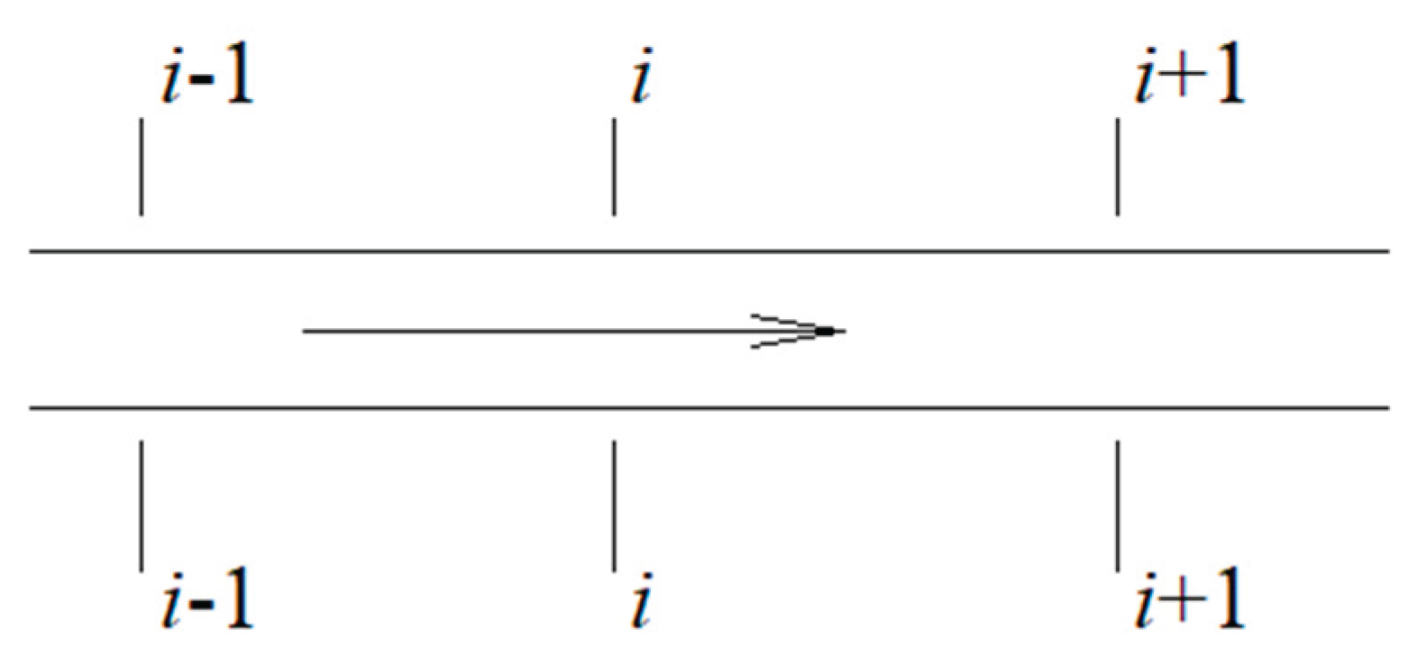
Figure 2.
Inlet node.
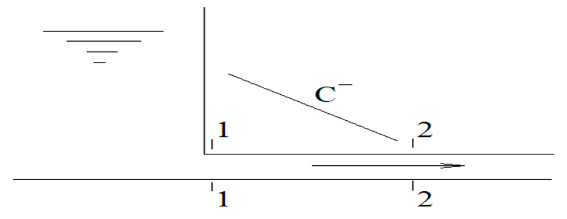
Figure 3.
Water Supply System Export Node.
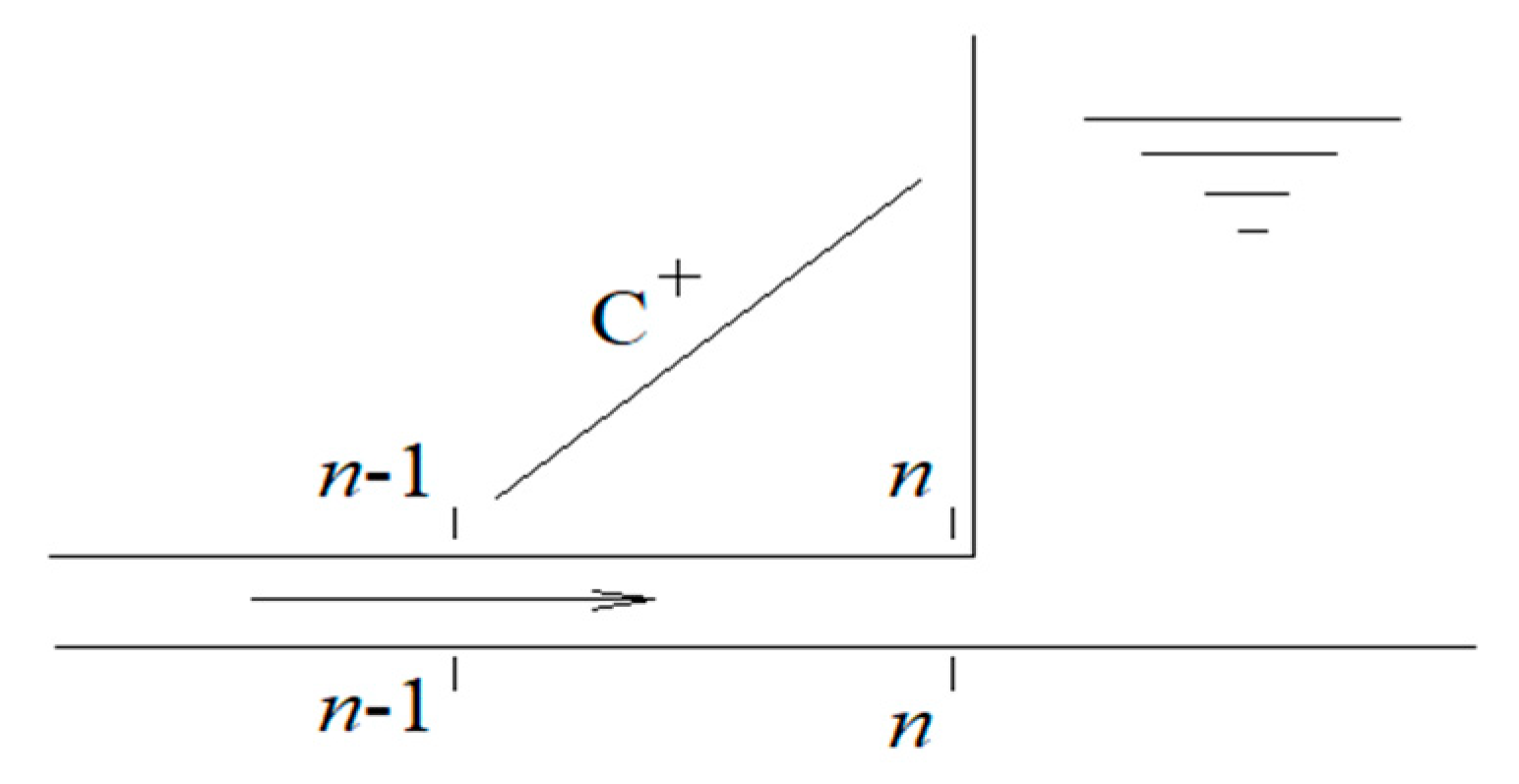
Figure 4.
Regulating Valve Node.
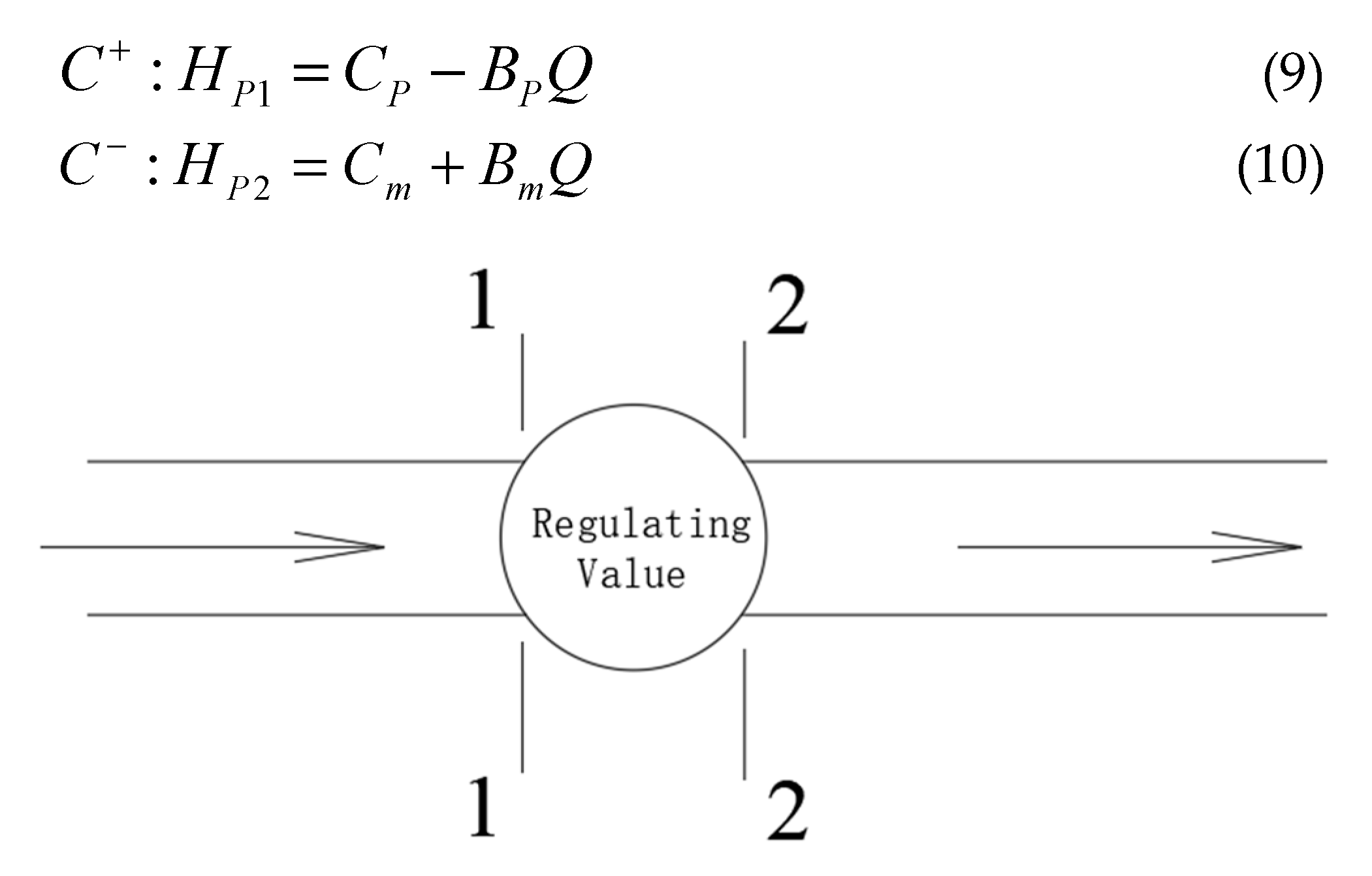
Figure 5.
Diagram Decompression pool construction.
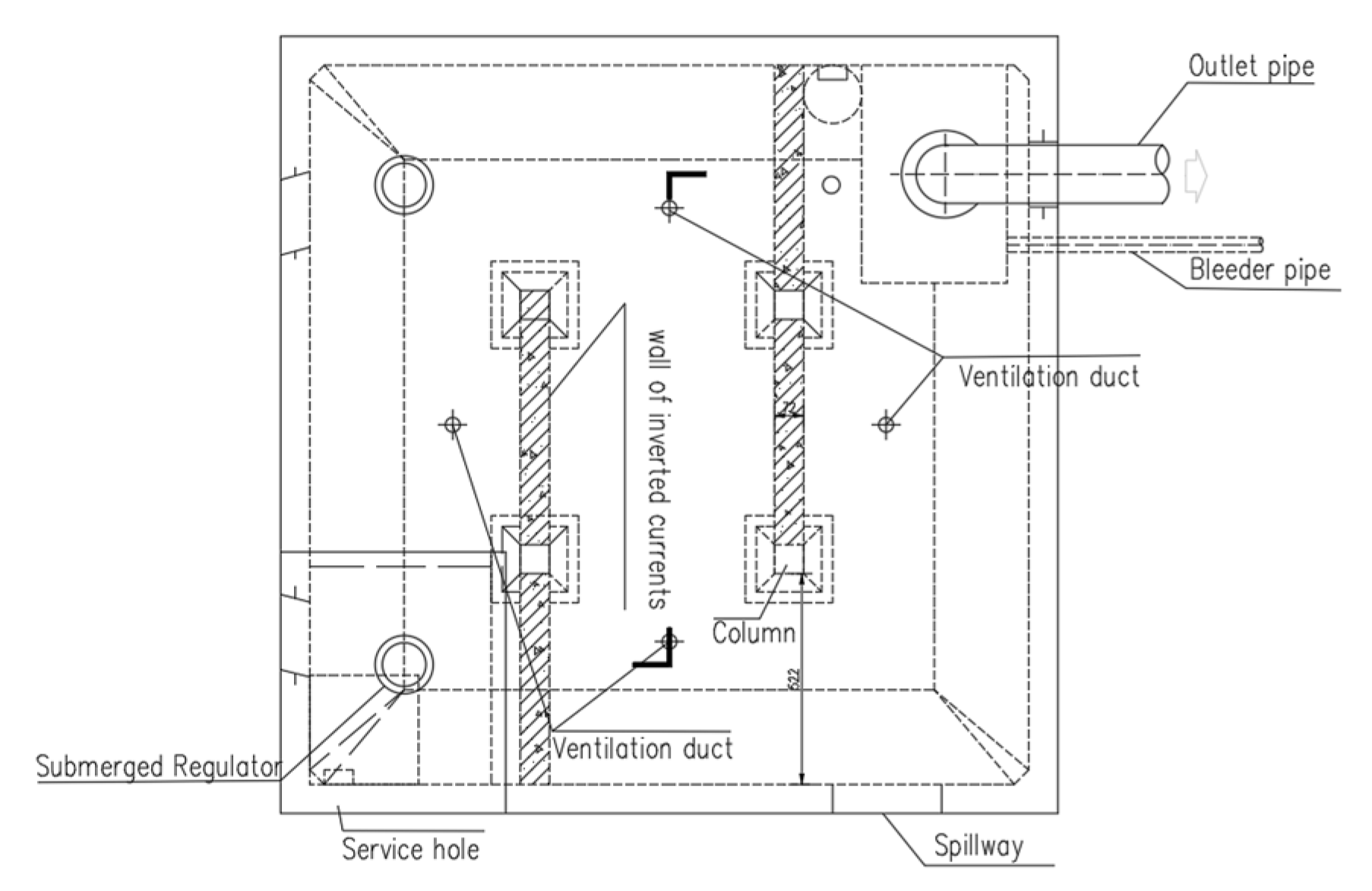
Figure 6.
Submerged multi-orifice flow control valve.

Figure 7.
Dead water level: Pressure head distribution of the main water supply pipeline and each branch pipeline along the line during constant flow.
Figure 7.
Dead water level: Pressure head distribution of the main water supply pipeline and each branch pipeline along the line during constant flow.
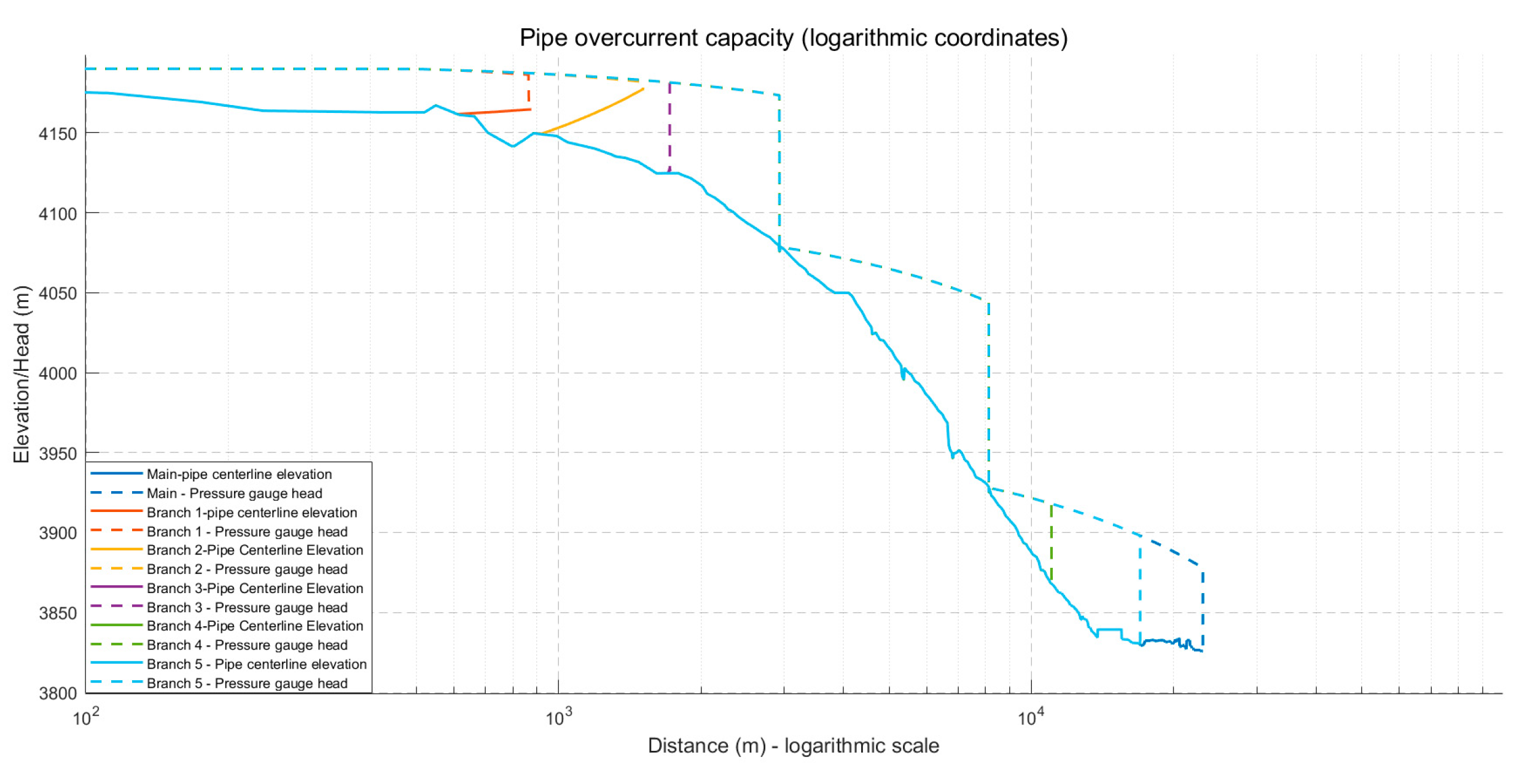
Figure 8.
Pressure head of the measuring pipe upstream of the valve regulating the closed valve.
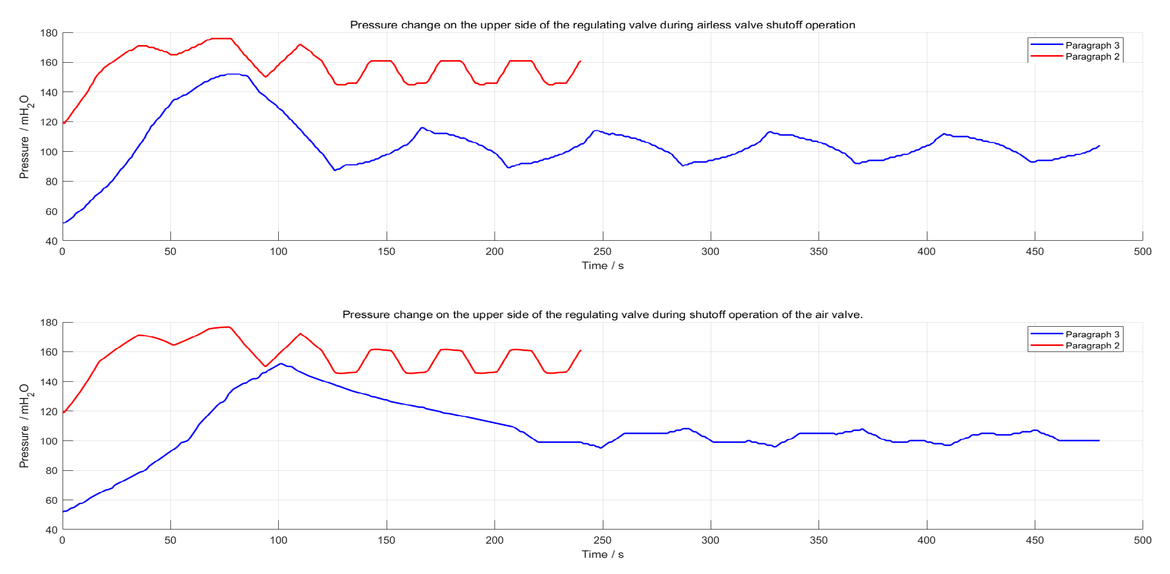
Figure 9.
Pressure head of the measuring pipe upstream of the valve regulating the open valve.
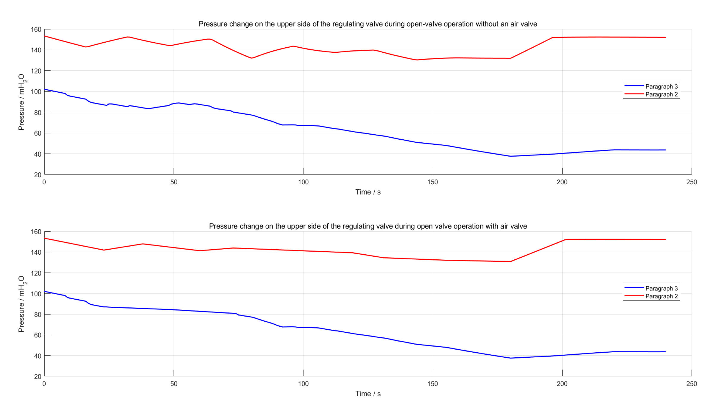

Table 1.
Analysis of the Influence of the Closing Patterns of Water Supply Main Pipe End Control Valves.
Table 1.
Analysis of the Influence of the Closing Patterns of Water Supply Main Pipe End Control Valves.
| Control Scheme Number | Valve Closure Time (s) | Valve Control Strategy | Hmax (m) | Hmax Location | Hmin (m) | Hmin Location |
| A1 | 60 | Linear closure, without protection | 221 | Terminal control valve (upstream) | -1 | K7+575.02~K7+586.65 |
| A2 | 120 | Linear closure, without protection | 152.27 | 0 | ||
| A2* | 120 | Linear closure, with surge protection | 152.27 | 2.04 |
Table 2.
2# Analysis of the Impact of Closing Patterns of the Regulating Valve at the Front End of the Pressure Relief.
Table 2.
2# Analysis of the Impact of Closing Patterns of the Regulating Valve at the Front End of the Pressure Relief.
| Control Scheme Number | Valve Closure Time (s) | Valve Control Strategy | Hmax (m) | Hmax Location | Hmin (m) | Hmin Location |
| B1 | 30 | Linear closure, without protection | 305 | Front-end control valve of No.2 pressure relief tank (upstream) | -10 | K2+385.00~K2+385.00 |
| B2 | 60 | Linear closure, without protection | 208 | -1 | ||
| B3 | 120 | Linear closure, without protection | 176.48 | 1.06 | ||
| B3* | 120 | Linear closure, with surge protection | 176.48 | 2.05 |
Table 3.
1#Analysis of the Impact of the Closing Pattern of the Front-End Regulating Valve of the Pressure Reducing Pool.
Table 3.
1#Analysis of the Impact of the Closing Pattern of the Front-End Regulating Valve of the Pressure Reducing Pool.
| Control Scheme Number | Valve Closure Time (s) | Valve Control Strategy | Hmax (m) | Hmax Location | Hmin (m) | Hmin Location |
| C1 | 30 | Linear closure, without protection | 254 | Front-end control valve of No.1 pressure relief tank (upstream) | 50.4 | D0+110 |
| C2 | 60 | Linear closure, without protection | 199 | 50.4 | ||
| C3 | 120 | Linear closure, without protection | 170.51 | 50.4 | ||
| C3* | 120 | Linear closure, with surge protection | 170.51 | 50.4 |
Table 4.
Analysis of the Opening Rules of the Water Supply Mainline End Control Valve.
| Control Scheme Number | Valve Opening Time (s) | Valve Control Strategy | Hmax (m) | Hmax Location | Hmin (m) | Hmin Location |
| D1 | 60 | Linear opening, without protection | 102.68 | K22+315~K22+511.29 | -0.04 | K7+575.02~K7+596.65 |
| D2 | 120 | Linear opening, without protection | 102.68 | -0.02 | ||
| D3 | 180 | Linear opening, without protection | 102.68 | 0.05 | ||
| D3* | 180 | Linear opening, with surge protection | 102.68 | 2 |
Table 5.
2#Analysis of the Opening Regulation of the Pressure Relief Valve at the Front End of the Pressure Relief Pool.
Table 5.
2#Analysis of the Opening Regulation of the Pressure Relief Valve at the Front End of the Pressure Relief Pool.
| Control Scheme Number | Valve Opening Time (s) | Valve Control Strategy | Hmax (m) | Hmax Location | Hmin (m) | Hmin Location |
| E1 | 60 | Linear opening, without protection | 153.39 | Front-end control valve of No.2 pressure relief tank (upstream) | -0.82 | K2+385~K2+395.51 |
| E2 | 120 | Linear opening, without protection | 153.39 | -0.38 | ||
| E3 | 180 | Linear opening, without protection | 153.39 | 1.58 | ||
| E3* | 180 | Linear opening, with surge protection | 153.39 | 2.29 |
Table 6.
1#Analysis of the Impact of the Opening Pattern of the Pressure Relief Valve at the Front End of the Pressure Relief Pool.
Table 6.
1#Analysis of the Impact of the Opening Pattern of the Pressure Relief Valve at the Front End of the Pressure Relief Pool.
| Control Scheme Number | Valve Opening Time (s) | Valve Control Strategy | Hmax (m) | Hmax Location | Hmin (m) | Hmin Location |
| F1 | 30 | Linear opening, without protection | 154.58 | Front-end control valve of No.1 pressure relief tank (upstream) | 50.4 | D0+110 (canal head section) |
| F2 | 60 | Linear opening, without protection | 154.58 | 50.4 |
Table 7.
Air valve position and parameters.
| Serial Number | Pile Number | Air Valve Diameter | Serial Number | Pile Number | Air Valve Diameter |
| 1 | K0+105.65 | 10 cm | 17 | K9+387.90 | 10 cm |
| 2 | K0+343.35 | 10 cm | 18 | K10+387.90 | 10 cm |
| 3 | K0+920.98 | 10 cm | 19 | K11+387.90 | 10 cm |
| 4 | K1+238.50 | 10 cm | 20 | K12+333.00 | 10 cm |
| 5 | K1+985.14 | 10 cm | 21 | K13+283.17 | 10 cm |
| 6 | K2+371.04 | 10 cm | 22 | K14+113.00 | 10 cm |
| 7 | K2+443.39 | 10 cm | 23 | K14+943.14 | 10 cm |
| 8 | K3+151.99 | 10 cm | 24 | K15+843.00 | 10 cm |
| 9 | K3+927.30 | 10 cm | 25 | K16+849.60 | 10 cm |
| 10 | K4+134.60 | 10 cm | 26 | K17+585.00 | 10 cm |
| 11 | K4+839.67 | 10 cm | 27 | K18+455.00 | 10 cm |
| 12 | K5+601.57 | 10 cm | 28 | K19+575.00 | 10 cm |
| 13 | K6+091.93 | 10 cm | 29 | K19+995.00 | 10 cm |
| 14 | K6+579.42 | 10 cm | 30 | K21+069.00 | 10 cm |
| 15 | K6+979.41 | 10 cm | 31 | K22+420.00 | 10 cm |
| 16 | K7+566.5 | 10 cm | 32 | D0+418.00 | 10 cm |
Disclaimer/Publisher’s Note: The statements, opinions and data contained in all publications are solely those of the individual author(s) and contributor(s) and not of MDPI and/or the editor(s). MDPI and/or the editor(s) disclaim responsibility for any injury to people or property resulting from any ideas, methods, instructions or products referred to in the content. |
© 2025 by the authors. Licensee MDPI, Basel, Switzerland. This article is an open access article distributed under the terms and conditions of the Creative Commons Attribution (CC BY) license (http://creativecommons.org/licenses/by/4.0/).
Copyright: This open access article is published under a Creative Commons CC BY 4.0 license, which permit the free download, distribution, and reuse, provided that the author and preprint are cited in any reuse.


