Submitted:
06 May 2025
Posted:
09 May 2025
You are already at the latest version
Abstract
Switched Reluctance Machines (SRMs) are gaining increasing traction within the industrial sector, primarily due to their inherently simple and robust structure. Nevertheless, SRMs are characterized by two major drawbacks: high torque ripple and strong radial forces, both of which render them less suitable for applications requiring smooth operation, such as Electric Vehicles (EVs). To address these limitations, researchers and designers focus on optimizing these critical performance metrics during the design phase. In recent years, the concept of System-Level Design Optimization (SLDOM) has been introduced and applied to SRM drive systems, where both the machine and the controller are simultaneously considered within the optimization framework. This integrated approach has shown significant improvements in mitigating the aforementioned issues. This paper aims to review existing literature concerning SLDOM applied to SRMs, highlighting key methodologies and findings from studies conducted in recent years. Despite its promising outcomes, the adoption of SLDOM remains limited due to its high computational cost and complexity. In response to these challenges, the paper discusses complementary techniques used to enhance the optimization process, such as search space and computational time reduction strategies, along with the associated challenges and potential solutions. Finally, two critical directions for future research are identified, which are expected to influence the development of SLDOM and its application to SRMs in the coming years.
Keywords:
system-level design optimization
; switched reluctance machine
; multilevel optimization
; surrogate models
; artificial neural networks
; machine learning
1. Introduction
Electrical machines play a crucial role in industrial applications, and their demand is continuously increasing. The largest share of machines in the industry is occupied by Permanent Magnet Synchronous Machines (PMSMs) due to their high power density, thanks to the permanent magnets, and Induction Machines (IMs) because of their simplicity in construction and operation, as well as their minimal maintenance requirements. However, the scarcity of rare earth metals used in the permanent magnets of PMSMs and the low power factor of IMs, combined with the significant losses in the rotor, have led the research community in recent years to explore new machine topologies to gain a stronger foothold in industry [1,2].
Switched Reluctance Machines (SRMs) do not incorporate magnets as found in PMSMs, nor do they feature windings or bars on the rotor like IMs. This distinctive characteristic, coupled with their intrinsic fault tolerance owing to their polyphase structure, high efficiency, and low core losses, renders SRMs a robust and reliable machine topology. Figure 1 illustrates various topologies of SRMs. While a detailed discussion on SRMs falls outside the scope of this paper, interested readers may consult the following textbooks for further information [3,4,5]. These attributes make them particularly well-suited for operation in demanding environments, such as those encountered in mining and drilling applications, where extreme temperatures and pressures are present [6,7]. However, due to their high saliency in both the stator and rotor, SRMs exhibit significant torque ripple and generate parasitic acoustic noise because of vibration forces. These drawbacks render SRMs less suitable for high-speed applications, such as aerospace systems [7], water pumps [8], and superchargers [9], and electric propulsion systems like EVs and Hybrid EVs (HEVs), where smooth operation and noise reduction are critical [10,11].
Optimization of the design process is the most widely employed strategy by researchers to mitigate torque ripple, acoustic noise, and the overall cost of the SRM structure. Through this approach, the desired objectives can be reduced, leading to an optimized machine that meets the specific requirements of its intended application [12,13]. The design optimization process is generally divided into two main categories: design and optimization. In the first category, the objective is to model the machine's structure and operation, define the parameters and goals of the optimization process, and identify feasible candidates that represent the optimal performance of the machine. In the second category, optimization algorithms are applied to identify and evaluate the most suitable candidate from the aforementioned set. This is done by searching for an optimal solution using Single-Objective optimization [14,15] or a set of optimal solutions, known as the Pareto front, in the case of Multi-Objective optimization [16,17], within a predefined search space.
However, certain applications, such as EVs and HEVs, necessitate a well-integrated drive system that includes the machine the controller, and power electronics such as inverters, to function effectively [1]. Optimizing the machine alone does not inherently ensure optimal system performance, as its operation is ultimately governed by the controller. Conversely, a suboptimal controller design may exacerbate torque ripple or limit the power delivered to the machine. [18]. Therefore, optimizing at the component level may not ensure the overall performance of the drive system, as the system is strongly interdependent. In these cases, a System-Level optimization approach is required to simultaneously optimize the entire drive system to achieve the desired performance and efficiency.
This paper presents the current state of System-Level Design Optimization Method (SLDOM) for SRM drives, highlighting existing challenges and identifying potential solutions for its implementation. Although the study was conducted with a focus on Switched Reluctance Machines, most of the existing literature concentrates on motor applications, with only a limited number of studies addressing generator configurations. Section 2 maps out the SLDOM, dividing it into two categories—Single-Level and Multi-Level. Section 3 design space reduction, primarily through the use of surrogate models and parameter criticality assessment, while presenting research conducted on these topics with a focus on SRM drives. Section 4 proposes a method for control enhancement and acceleration of optimization through SLDOM. Finally, Section 5 discusses future research directions based on the SLDOM and Section 6 concludes this paper.
2. System-Level Design Optimization
Unlike conventional design and optimization practices that treat components in isolation, SLDOM treats the system as a whole—the controller, power electronics, and machine—into one single optimization framework. This integrated approach accounts for interdependencies, feedback loops, and cross-coupling interactions that are typically neglected under traditional methodologies. Hence, SLDOM results in an improved and more precise optimization path, especially in large systems such as SRM drives. This method permits engineers to analyze performance metrics not only at the component level, but in conjunction with system-level interactions. For instance, design decisions related to the motor can influence control strategies, thermal behavior, and system efficiency overall. System-level optimization is therefore required to obtain balanced trade-offs between competing objectives like cost, performance, and reliability.
2.1. Methodology and Framework
When implementing System-Level Optimization methods, a consensus on five key steps is identified, which ensure that the full potential of the approach is realized [19,20,21]. These seem to offer a well-rounded and systematic procedure that addresses the complexities inherent in optimizing drive systems. The multi-step methodology appears to provide a comprehensive framework for balancing various competing factors between machine and controller, such as efficiency and cost, within the design process. The steps are laid out with clarity that offers a solid foundation for both further research and practical applications in the field.
Step 1: Definition of the system's overall requirements and design objectives. The system requirements are determined, such as efficiency, torque ripple, average torque, weight, and cost. Constraints are defined, like maximum current, minimum efficiency, and search limits of each parameter for the optimization algorithm, primarily based on the application in which the implementation is carried out.
Step 2: Definition of the drive system characteristics, including both the machine and the controller. In this step, the machine's topology and specifications are selected, alongside the controller, which includes power electronics such as the inverter and control algorithms, to ensure proper functionality. The selection process between the machine and controller can be a complex task, as these two components are highly interdependent and coupled, often requiring expertise and experience.
Step 3: Design of the drive system. Machine design involves modeling and material property selection, as well as multiphysics analyses such as electromagnetic, thermal, and mechanical considerations. The controller design encompasses the selection of the control algorithm, inverter topology, and power electronics.
Step 4: Selection of optimization algorithms for the entire system. Each level (machine, controller) may employ its own Single-Objective or Multi-Objective optimization algorithm, tailored to the specific requirements of that layer.
For the machine level, the optimization procedure is as follows:
Where fm, gm represent the machine objective and constraint functions respectively, xm denotes the machine design parameters, with xl and xu being the lower and upper boundaries of the search space, respectively. Nm is the number of machine constraint parameters.
Subsequently, for the control level, the optimization procedure is as follows:
 Where fc, gc represent the control objective and constraint functions, respectively, xc is the control design parameter with xl and xu as the lower and upper boundaries of the search space respectively. Nc is the number of control constraints parameters.
To construct the final System-Level Optimization problem, equations, (1) and (2) should be combined as follows:
 Where fsys and xsys represent the overall system objective and design parameters respectively, with fsys being a function of fm, fc and design parameters. [xm, xc] now correspond to the machine and control design parameters, with xl as the lower and xu as the upper boundaries of the search space. Nsys denotes the number of system constraint parameters.
Step 5: Evaluation of overall system performance, which includes the assessment of both steady-state and dynamic performances as follows:
- At steady state, the evaluation focuses on the machine’s performance, including efficiency, weight, average torque, and cost.
- At dynamic state, the evaluation examines the performance of the controller and the overall drive system, considering factors such as speed overshoot, settling time, torque ripple, and system cost.
The course of the methodology and the steps developed previously are also presented schematically in Figure 2. Each colored section corresponds to a step in the methodology, which provides more detailed information for each step, with the first one being the “Drive System Design” block.
In summary, the optimization problem is structured into three main branches: the Machine Level, the Control Level, and the System Level. At each level, the System-Level Optimization Methodology conducts an optimization process aimed at maximizing overall system performance. The first two levels, referred to as the Component Level, focus on refining their respective elements. While individual components may not be optimized independently, the methodology ensures the optimal performance of the overall system.
System-Level Optimization Methods
There are two approaches regarding System-Level optimization based on the procedure of optimization and evaluation. These are Single-Level Optimization Method (SLOM), which treats the system as a unified entity, and Multi-Level Optimization Method (MLOM), which optimizes each component sequentially and evaluates the system holistically [19,22]. Both methods aim to optimize the entire system, with the latter being computationally less expensive due to the division of the optimization process into two separate parts: the machine and the controller. Nevertheless, both methods have been utilized in relevant studies, with the former approach being preferred due to its simplicity in implementation.
2.2.1. Single-Level Optimization Method
The logic behind the Single-Level Optimization Method is that both the machine and the controller are optimized simultaneously, and the results are evaluated at the same time. The SLOM framework steps are [23]:
Steps 1-3: Identical to the general framework described above.
Step 4: Selection of the optimization method. In this step, an optimization method is chosen that will simultaneously optimize both the machine and the controller.
Step 5: Implementation of the optimization method and evaluation. The final step involves implementing the optimization algorithm for the selected drive system parameters and evaluating the performance of the drive system. This step is repeated until the optimization goals are met. The aforementioned steps are also illustrated in Figure 3, which outlines the general structure of the methodology. It should be noted that, in the last two steps, the optimization and evaluation of both the machine and the controller are carried out simultaneously. The determination of the optimal design is thus performed holistically for the entire system, rather than independently for each component.
The primary drawback of this optimization method is the significant computational burden placed on the computer due to the complexity of the problem and the simultaneous optimization of both the machine and the controller. This challenge is particularly evident when numerical methods, such as the Finite Element Method (FEM), are employed. Below, relevant studies based on this method are presented. Their analysis reveals that the choice of this approach was primarily driven by its simplicity rather than the reduction of computational time.
Authors in [24] proposed a method that integrates Mamdani fuzzy inference system for drive system modeling with the Non-Dominated Sorting Genetic Algorithm III (NSGA-III) for an application in Switched Reluctance Generator. This new approach called Fuzzy Inference NSGA-III performs simultaneous optimization of both the machine and the controller through the adjustment of geometric parameters of the generator and turn-on angle θon and the conduction angle θc of the controller. By extracting the results, a comparison is made between the outcomes of the proposed method and those of NSGA-II. The results of the former are more improved, but not significantly. However, the study does not specify the software used for analysis and simulation, which could provide valuable insight into the implementation process. Moreover, the algorithm does not yield a global optimum value but rather a range of values within which the optimal value lies. Additionally, the authors could have included wider parameter ranges for the optimization process, in order not to limit the algorithm’s ability to identify the true optimal value.
In [25], the authors investigate the design of an SRM drive system for application in vertical transportation using JMAG software for system modeling. They perform optimization using Genetic Algorithm (GA) on the motor, selecting one of four possible motor models, and on the controller, optimizing both the geometric characteristics of the motor and the turn-on θon and turn-off θoff angles of the controller. Their objective is to optimize the RMS current, torque ripple, and torque output. Finally, they evaluate the system's performance under both steady-state and dynamic conditions using MATLAB/Simulink. However, the study does not provide details on the optimization process of the motor’s geometry, focusing solely on the control optimization.
Reference [26] proposes a modeling and optimization framework for an SRM drive system, which utilizes FEA-based method through ANSYS simulation software for steady-state operation and analytical equations to describe the system’s dynamic behavior. Optimization is performed using the Particle Swarm Optimization (PSO) algorithm to determine the optimal current values that minimize torque ripple and voltage peaks and extract the corresponding current profile. The current profiling construction and the methodology allow the dynamic state of the motor to be estimated solely through its static analysis. This approach significantly reduces the time required for holistic optimization. However, there is a slight trade-off in accuracy, as not all transient state phenomena are considered during the dynamic analysis. The results show very low torque ripple and an almost square current waveform.
Reference [27] focuses on the design of an SRM for Aerospace Applications by utilizing field-circuit coupled FEM and incorporating a loss density function as a constraint for thermal properties. The Multi-Objective problem is transformed into a Single-Objective one through the loss density function applied to efficiency. FEM is employed for the motor, while field-circuit analysis is used for the inverter, which utilizes the Asymmetric Half-Bridge Converter (AHBC). In the controller, the switching angles θon and θoff are considered as parameters, and the design parameters are optimized simultaneously with the help of GA. The results, presented through static analysis, demonstrate improvements, including a slight increase in efficiency and reductions in torque ripple, mass, and loss density.
In [28], the authors discuss the design of an SRM for an In-Wheel application in EVs by conducting a static analysis using FEM through MotorSolve and MATLAB. The NSGA-II algorithm is employed as an optimizer to enhance the average torque, torque ripple, and motor efficiency by modifying both motor and controller variables. The results indicate that the initial design objectives were successfully met, ensuring that the motor fulfills the required operational criteria set by the designer, with a slight improvement over the initially defined targets.
In the aforementioned studies [24,25,26,27,28], the authors do not present the computational time required to complete the simulation, and given that the data is extracted using FEM, the computational time is expected to be substantial. A comprehensive search across the entire design space as defined by the designer based on the selected parameters can be prohibitive when using FEM for every iteration. One potential solution would be to incorporate a complementary space-reduction technique or to impose narrower parameter limits. However, this approach carries the risk that an acceptable solution may not exist within the predefined constraints.
2.2.2. Multi-Level Optimization Method
The Multi-Level Optimization Method differs from the Single-Level approach by dividing the process into distinct stages: the Machine Level, the Control Level, and the System Level. Optimization and evaluation are performed independently until the final level, where the entire drive system is evaluated. This staged approach helps distribute the computational workload, preventing excessive strain on the computer at each step [20,29].
The following steps outline the process of implementing the MLOM:
Step 1: Definition of the Machine and Control Level models and objectives. At each level, specific objectives are defined—for example, efficiency, average torque, torque ripple, mass, and cost for the machine; and settling time, overshoot, and cost for the controller. Additionally, constraints such as maximum current, minimum efficiency, and the search space are specified, along with the optimization algorithms to be employed.
Step 2: Optimization of each level independently. In this step, the Machine and Control Levels are optimized separately from one another. First, the optimization process is applied to the machine, followed by the optimization of the controller.
- 3.
- Machine Level: Design optimization is carried out for the machine, and the steady-state performance of the machine is evaluated, including efficiency, weight, average torque, and cost. Key machine parameters, such as resistance, flux linkage, and inductance, are then passed on to the next step to be used as inputs at the control level.
- 4.
- Control Level: At this level, optimization of the controller is performed based on the output parameters from the previous level. The dynamic performance of the drive system is then evaluated, focusing on speed overshoot, settling time, and torque ripple.
Step 3: The final step is the System Level, where the overall drive system is evaluated, and the results are verified.
It should be noted that each step concludes and proceeds to the next when the optimization algorithm has achieved the defined objectives. As a result, both steady-state and dynamic performances are optimized in the final step, ensuring that the methodology follows a sequential logic. Figure 4 shows the MLOM framework, highlighting this sequential logic applied during the optimization and evaluation steps mentioned earlier.
In [30] the authors propose a novel approach for the design and optimization of a SRM for EV application using a novel Multi-Objective Design Optimization (MODO) algorithm. Their methodology couples the Kriging surrogate model constructed in ALTAIR FLUX with MATLAB/Simulink to simulate motor operation and utilizes the NSGA-II algorithm for optimization. Initially, the algorithm optimizes the geometric characteristics of the motor, selecting the best design that maximizes the average torque. Subsequently, it optimizes the turn-on θon and turn-off θoff angles. However, the study evaluates only dynamic performance, arguing that the steady-state condition does not significantly impact the overall system performance. While it is true that certain applications predominantly operate under dynamic conditions, the inclusion of steady-state analysis can offer valuable insight into key performance aspects, such as efficiency, losses, and thermal behavior, which are often not fully captured in transient simulations. Furthermore, steady-state evaluations are typically computationally efficient, enabling their integration into the design and optimization process without imposing significant additional complexity.
Reference [31] focuses on the design of an SRM using a nonlinear electromagnetic analysis model combined with circuit theory for an EV application. The proposed model is validated through FEM and random variables are introduced to define the wind resistance coefficient, rolling resistance coefficient, and slope in order to simulate various road conditions in the dynamic operation of an EV. Torque, efficiency and torque ripple are optimized using Single-Objective Optimization carried out by GA. The torque ripple and controller efficiency are optimized by adjusting turn-on θon and turn-off θoff angles. This approach qualifies as a MLOM since the parameters are optimized in successive steps rather than simultaneously. Typically, control optimization is performed under dynamic conditions. However, the study reports a very high torque ripple coefficient of approximately 1.55, which translates to 155%, while efficiency remains below 90%. Additionally, the computational time of the method is not discussed.
In the previous references, in both SLOM and MLOM, the optimization process utilizes the entire solution search space, even if some solutions are neither feasible nor exploitable by the optimization algorithms. This approach imposes a computational burden on the optimization algorithm in terms of processing power and time. Therefore, these solutions and the search space should be reduced accordingly.
3. Model Complexity and Space Reduction Techniques for System-Level Optimization
System-Level Design Optimization can be conducted exclusively using FEM; however, its massive computational requirements renders it an expensive method. Therefore, several techniques have been proposed and employed to mitigate computational burden. Figure 5 illustrates various techniques that have been adopted in the literature to reduce the computational time of the optimization process by reducing the overall model complexity by adopting surrogate models such as interpolation-based methods, like the Kriging Model and the Response Surface Method, as well as Machine Learning-based algorithms such as neural networks. In addition, the reduction of critical design parameters prior to optimization through the use of search space reduction techniques is commonly achieved with techniques such as Sensitivity Analysis, Design of Experiments (DoE), and the Taguchi Method.
3.1. Surrogate Modeling
Surrogate models aim to establish a relationship between the input and output parameters of the problem they are attempting to solve. In the design and optimization of electrical machines, the input parameters are the design parameters used in the optimization process, while the output parameters are those that require optimization, such as efficiency, cost, weight, average torque and torque ripple. Their main advantage lies in the significantly reduced computational time required to simulate an optimization problem. For this reason, they are often preferred over FEM, due to the excessive computational time demanded by the latter method. However, since surrogate models are constructed through analytical formulas, they lack the precision of FEM, particularly in their inability to accurately simulate the nonlinear behaviors of electrical machines, especially SRMs, such as saturation and mutual coupling between phases. Despite this disadvantage, their use is widespread in the field of electrical machine design optimization, as the reduction in computational time is considerably important relative to the accuracy they sacrifice, especially at the System Level, where optimization of both the motor and the controller is required. Popular surrogate models include Kriging model, Radial Basis Functions (RBFs), Response Surface Method (RSM), and Artificial Neural Networks (ANNs) [32,33].
Ιn [34], authors propose the design of a novel SRM drive topology aimed at minimizing torque ripple. Their approach involves investigating the rotor pole shape by introducing specific grooves. A surrogate model, specifically a proxy model trained using quadratic polynomial regression, is employed alongside the Multi-Objective Genetic Algorithm (MOGA) for optimization. The objective is to reduce torque ripple while increasing the average torque, implemented within MATLAB/Simulink. Initially, optimization is performed on the motor, followed by controller optimization through the adjustment of the turn-on θon and turn-off θoff angles. The results indicate a significant reduction in torque ripple—up to 72%—with a slight increase in average torque. However, the study lacks dynamic state performance analysis, which is crucial for assessing whether the controller, and consequently the motor, can effectively respond to dynamic conditions. In many cases, dynamic state performance evaluation is neglected due to the additional computational burden it imposes on the optimization procedure. Nevertheless, it remains a critical analysis that should be incorporated to ensure robust and reliable system performance.
3.1.1. Kriging Model
The Kriging model is an interpolation method based on the Gaussian process that employs a stochastic approach to identify the relationship between optimization variables and objective functions using known data, most often extracted from FEM simulations. A key feature of the Kriging model is its ability to represent the correlated error and the predictable variance in each simulation [32,35]. Figure 6 illustrates the approximation of the input–output relationship using the Kriging model in comparison to the actual response. In addition, it visualizes the correlated errors (Interpolation variance) previously discussed.
In [30,36] the authors employ the Kriging model, coupled with the NSGA-II algorithm to establish a correlation between variables and optimization parameters to optimize the motor. In [36] they aim to mitigate the mutual coupling between two adjacent phases due to the presence of an even number of phases, which creates asymmetry in the current. To address this issue, they optimize the stator yoke and the controller through the turn-on angle θon and conduction width of the current pulse. The results obtained from the Kriging model, trained with data from ANSYS software, exhibit slight deviations from those of FEM but are derived in significantly less time, whereas FEM would require 105 simulations.
Authors in [37] discuss the design of an SRM through System-Level Optimization, specifically Multi-Level Optimization (MLO). Sensitivity Analysis is employed to classify parameters based on their significance, while the motor is modeled using the Kriging method. Shape Optimization is applied via the Bezier curve to modify the rotor pole shape and enhance performance, the control optimization is conducted through the turn-on θon and turn-off θoff angles and, as an optimization algorithm, NSGA-II is utilized. Validation is performed using the ANSYS Suite for FEM, leading to minimal error between Kriging and FEM. Although losses slightly increase, average torque and torque ripple are marginally optimized. Similarly, in [38] Kriging model is used in conjunction with the NSGA-II algorithm for optimization with the control parameters being the turn-on θon and turn-off θoff angles. Model data are validated once again, and it is concluded that the errors between Kriging and FEM are small, with a maximum error of 3.17 % for torque ripple, which is considered highly accurate and reinforces the significance of the Kriging model. However, the entire analysis reduced the initial torque ripple from 93.64 % to 47.84 %, which remains relatively high, and, additionally, the overall losses increased.
In [39], the authors focus on the design of a 12/10 SRM for EV applications, utilizing driving cycle data and the Dimension Reduction Optimization Method (DROM) to reduce the solution search space. This reduction is performed iteratively at each step until the optimal point is found, progressively narrowing the range of each parameter. Kriging model is employed using data extracted from FEM simulations in ANSYS/Maxwell, simulating four different driving conditions. Verifications demonstrate errors below 1%. After each simulation, Pearson Correlation Analysis is applied to simplify the optimization process and eliminate redundancies. The study highlights that the proposed method significantly reduces computational time—where a full FEM-based approach would require 750 simulations. The results indicate an increase in torque and a reduction in ripple across all driving conditions.
Finally, in [40] a study is conducted on the design of an SRM using FEM and the Transient Lumped-Parameter Thermal Model (TLPTM), considering the thermal analysis of the motor. Additionally, the Kriging model is constructed using FEM in Ansys/Maxwell 2D with 500 simulations, and NSGA-II is employed for optimization. The control optimization is performed through the turn-on θon and turn-off θoff angles, resulting in a reduction of torque ripple, an increase in torque, and a decrease in the temperature of the windings and the stator, all of which are optimized to a satisfactory degree.
3.1.2. Response Surface Method
Similarly to the Kriging model, the Response Surface Method is an interpolation technique that primarily uses data from FEM to construct a response surface for both known and unknown data. It employs the least squares method to derive a correlation between input and output parameters [41,42]. Figure 7 illustrates the torque surface based on the Response Surface Method for the input variables rotor position and excitation current for a specific SRM motor. This surface response also qualitatively depicts the relationship between torque, rotor position, and excitation current for the SRM.
An analysis is performed in [43] on a 24/16 (number of stator poles/number of rotor poles) SRM motor for application in an in-wheel EV using FEM and Design of Experiments (DoE) to reduce the solution search space, coupled with RSM and Differential Evolution (DE). Design candidates are generated through FEM in ANSYS, and the RSM is implemented via DoE to reduce the search space. Simultaneously, for control optimization, the optimal turn-on θon and turn-off θoff angles are determined using a sweep method in MATLAB to optimize the average torque, torque ripple, losses, and RMS current. The results indicate a fivefold reduction in computational time, from 36 hours to 7 hours, while maintaining satisfactory optimization outcomes.
To the best of the authors’ knowledge, no other studies have been conducted employing this method for System-Level Optimization of SRMs, apart from those focused on component-level optimization. In [44] and [45], the authors utilize the RSM as a surrogate model for the optimization of a Synchronous Reluctance Machine and a dual-permanent-magnet-excited (DPME) machine, respectively. Notable results include an improvement in the rotor saliency ratio from 2.42 to 3.68, leading to an enhanced torque-to-current ratio and an increase in efficiency from 64.8% to 74.7% in the former, while the latter achieved an 8.9% reduction in permanent magnet material usage. Additionally, improvements in efficiency, a significant reduction in cogging torque, and minimized torque ripple were reported. What is particularly important to highlight is that the implementation of this methodology resulted in a substantial reduction in computational time, while maintaining a satisfactory level of accuracy, as indicated by the Coefficient of Determination R2. Thus, its application to SRM machines in a broader context of SLDOM could be highly beneficial.
3.1.3. Artificial Neural Networks
Artificial Neural Networks (ANNs) are Machine Learning (ML)-based models that have been increasingly developed in recent years for the design and optimization of electrical machines, as they can significantly reduce the computational burden associated with FEM-based design processes [46,47]. Their fundamental concept involves establishing a mapping between input and output parameters through a fitting process. Compared to other surrogate models, such as Kriging and the RSM, ANNs require a dataset for model training. They consist of three layers: input, output, and hidden as illustrated in Figure 8. Variables x and y are input and output values respectively. The accuracy of the model typically increases with the number of hidden layers; however, additional hidden layers may also lead to longer training times or overfitting. Accuracy can also be increased through model complexity and feature engineering. [46,48]. Architectures commonly used in electrical machine optimization include Feedforward Neural Network (FNN), Backpropagation Neural Network (BPNN), Radial Basis Function Neural Network (RBFNN) and Generalized Regression Neural Network (GRNN) [49].
Authors in [50] propose an optimization method for a high-power-density SRM drive, dividing the process into two stages. In the first stage, a static analysis is conducted to identify the parameters that yield the highest static torque. In the second stage, a dynamic analysis is performed on these parameters to optimize the average torque, torque ripple, and radial forces. This is achieved using RBFNN as surrogate model in combination with optimization algorithms such as GA, Particle Swarm Optimization (PSO), and Global Response Surface Method (GRSM). FEA is conducted using ALTAIR software, with model fitting performed either with RBFNN through ALTAIR HyperStudy or with ANN via Python. The study concludes that the fastest method is ANN combined with GRSM. For control optimization, the conduction angles are optimized using GA, and the results indicate that while the average torque and radial forces are improved, the torque ripple remains unchanged.
As with the case of RSM, and according to the research conducted by the authors, there is limited literature regarding the use of neural networks in SLDOM, with most studies focusing on component-level optimization instead. In [51] and [52], the authors focus on optimizing the motor by employing neural network models such as GRNN and Multilayer Perceptron Neural Network (MLPN), in combination with PSO and the Fly Optimization Algorithm (FOA), in order to reduce computational time. For instance, in [51], the computational time for optimization is reduced to just half an hour and an improvement is observed in the critical motor parameters, such as average torque, torque ripple, and efficiency. Additionally, the use of these methods facilitates the simulation of nonlinearities inherent in the SRM, making them ideal for further implementation in SLDOM.
3.2. Parameter Criticality Assessment
In this chapter, two essential space reduction methods—Sensitivity Analysis (SA) and Design of Experiments (DoE)—are categorized under the broader concept of Parameter Criticality Assessment. These methods analyze the influence each design parameter has on the overall system performance. If a parameter is found to have minimal impact, it is excluded from the optimization process, allowing only the critical parameters to remain. Ultimately, these techniques contribute to a significant reduction in computational time and provide the designer with valuable insight into which parameters need greater attention during the optimization process. They are particularly important in enabling the use of FEM in SLDOM.
3.2.1. Sensitivity Analysis
The Sensitivity Analysis approach is aimed at classifying the parameters intended for optimization based on how small variations in these parameters influence system performance. These variations may arise from inherent material imperfections, manufacturing defects, or constraints introduced by tolerances during the manufacturing process [53]. Essentially, this method allows the designer to eliminate parameters that have minimal or no impact and focus solely on optimizing the critical ones, thereby reducing the parameter space. Based on the above discussion, and the illustration in Figure 9, the most critical parameter is x1, while x2 appears to be the least influential for output variables y, as indicated by the qualitative “Sensitivity” metric.
In the studies [37,38,39,40,43,50] analyzed previously, Sensitivity Analysis serves as the fundamental pillar for further analysis. In [54], a study was conducted utilizing the Magnetic Parameter Design Methodology, which is based on the nonlinear properties of magnetic materials combined with analytical equations. Sensitivity Analysis is performed to determine the criticality of various parameters. Following this, the analysis identifies turn-on θon angle as the critical parameter for the controller and number of turns N as the critical parameter for the motor, optimizing both simultaneously. The proposed method is applied to three SRM topologies: a five-phase 10/8, a nine-phase 18/20, and a three-phase 12/8. The results are compared with FEM analysis, leading to the conclusion that minor errors exist but are justified.
Study [55] serves as a continuation of [26], where the proposed method is experimentally validated. Additionally, a form of Sensitivity Analysis is employed, utilizing a systematic down-selection process to determine the parameters for optimization. As a result, although the number of design parameters increased from six in [26] to eleven in [55], only the most critical parameters are selected at each iteration for further optimization. The study further compares the results obtained from voltage-fed analytical equations and FEM-based simulations under dynamic conditions. The findings indicate that the discrepancies between the two approaches remain within an acceptable range.
In [56], the authors focus on the design of an External Rotor Switched Reluctance Motor (ERSRM) by implementing Sensitivity Analysis and an improved version of the NSGA-II algorithm, referred to as CD-NSGA-II. This enhanced optimizer incorporates the Chi-square distance metric in contrast to the standard NSGA-II and is applied through MATLAB/Simulink and ANSYS. Sensitivity Analysis identifies the critical parameters as the θon and θoff angles, along with key geometric parameters of the motor. The optimization process targets torque ripple, average torque, and efficiency as the primary performance metrics. A comparative analysis between the two optimization algorithms is conducted, revealing that while CD-NSGA-II leads to a slight decrease in efficiency and an increase in losses, it achieves a significant reduction in torque ripple compared to NSGA-II. However, the study does not consider the effects of friction and windage losses in its analysis. The same author team in [57] extend their novel topology for the ERSRM featuring an asymmetric stator for application in E-Bikes. The optimization process employs the NSGA-II algorithm in conjunction with Sensitivity Analysis and FEM simulations to minimize torque ripple. The analysis and results align with their previous findings, demonstrating a significant reduction in torque ripple. However, similar trade-offs are observed, including a slight decrease in efficiency and a corresponding increase in losses.
3.2.2. Design of Experiments
The systematic method of designing and evaluating controlled experiments to assess critical variables in optimization procedure is known as Design of Experiments. This technique improves efficiency, by eliminating non-critical parameters, and accuracy by allowing designers to gather as much information as possible from fewer experimental runs [43,50]. DoE key techniques include the Taguchi method [58], which emphasizes robust design by minimizing variation; fractional factorial designs, which minimize the number of runs while maintaining crucial information; and full factorial designs, which examine every possible combination of factors. DoE is widely used in the electronics, automotive, and aerospace manufacturing sectors, optimizes design parameters for increased efficiency and reliability [59,60].
Study [43], previously discussed, successfully implements the DoE methodology, resulting in a notable reduction in the overall computational time of the optimization process. In [61], the authors discuss the design of a 12/10 hybrid excitation segmented-rotor SRM (HESRSRM), where magnets are placed in front of the openings in the stator slots. Taguchi method is employed, along with Sensitivity Analysis, to limit the search space and optimize the parameters. From the Taguchi method, 25 candidate models are generated, and optimization is applied to each model. The optimization focuses on reducing torque ripple, improving average torque, and minimizing losses using equations developed for the geometric characteristics, while the turn-on θon and turn-off θoff angles are indirectly calculated using these equations. Thus, this process can be considered an indirect System-Level Optimization. However, this approach does not account for the nonlinear characteristics of the system, which may affect the accuracy of the optimization results. For the static analysis of a single phase, ALTAIR FLUX software is used to extract the torque profile and the coupled flux, and ALTAIR FLUX is coupled with MATLAB/Simulink for dynamic operation of the motor. The optimization results indicate a significant increase in torque and power density, with only a slight reduction in ripple.
The following reference [62] address System-Level Optimization using Sensitivity Analysis from the perspective of Robustness. The authors propose a method which incorporates the driving cycle and multiple driving modes into the analysis. This method utilizes Sensitivity Analysis to eliminate non-critical parameters, combined with the Taguchi method for optimization. A case study of a 12/10 six-phase SRM is conducted to validate the method, where each design parameter, whether of the controller or the motor, affects different driving modes. The analysis is completed after four iterations, and the results show a significant reduction in torque ripple with a slight decrease in torque.
3.3. Sequential Subspace Optimization Method
The Sequential Subspace Optimization Method (SSOM) is an approach that falls under the category of Multilevel Optimization, as it performs optimization across multiple levels by dividing the overall search space. In contrast to the Single Space Optimization Method, which conducts optimization on a single level considering all design parameters simultaneously, the multilevel approach divides the problem into separate yet related subspaces in which the parameters defined for optimization are dedicated into based on their significance, with each subspace being optimized separately. This process is sequential, and at each level, the parameters of the other levels remain fixed. The entire process is iteratively repeated until a convergence criterion is met [12]. Figure 10 shows the SSOM framework, the most critical parameters are placed in the first level, while the least critical ones are assigned to the final level.
This method is particularly useful in cases where the number of optimization parameters and the solution search space are extensive, such as in System-Level Optimization [12,63,64]. Classification of parameters based on their significance is performed through Sensitivity Analysis, which evaluates the impact of small variations in each parameter on the overall system performance [63].
Initially, the authors in [20] and [65] mapped SLDOM framework and enhanced it with the SSOM and surrogate models such as Kriging, combined with Sensitivity Analysis. In [20], the optimization results are promising, showing an increase in output power, torque, and efficiency, while reducing cost, torque ripple, and losses. Additionally, the computational time with SSOM has been reduced by up to five times for the motor and twice for the control compared to a Single-Level Optimization method.
In references [37,38,40], system parameters are categorized into three levels—highly significant, significant, and non-significant—based on their criticality, followed by sequential subspace optimization. In [37], sensitivity analysis identifies the controller turn-on θon and turn-off θoff angles as the most critical parameters, placing them in the X1 subspace. Conversely, in [38], control and motor parameters are distributed across the three levels, with each level requiring fewer FEM simulations for optimization and only three iterations for the whole optimization process, highlighting the significance of the SSOM approach. Finally, in [40], the Kriging model is utilized in combination with Sensitivity Analysis and the SSOM to accelerate the optimization process. The parameters identified through sensitivity analysis are divided into three levels, with the most critical being the turn-off θoff angle and the air gap g. Only two iterations are required for the optimization algorithm to converge based on the termination criterion defined by the authors, resulting in a 16.17% improvement in overall system performance.
In [66], SSOM is utilized alongside the Kriging model and Sensitivity Analysis to optimize a SRM drive system. Design parameters are classified into the three subspaces while NSGA-II generates Pareto-optimal solutions through optimization. A termination criterion, based on the relative error between two successive iterations, determines the best design, leading to 42% increase in torque and torque ripple reduction around 65%. Only three iterations are required for the termination criterion to be satisfied, with each subspace requiring significantly less time for optimization compared to the first. This is logical, as the most critical parameters, which have the greatest impact on system performance, are placed in the first subspace. The last comment highlights the significance of Parameter Criticality Assessment, which refers to identifying the critical parameters and downplaying the influence of those with limited impact. Finally, this paper serves as a preliminary study for [38] by the same authors, which refines the approach by introducing multilevel optimization, better Kriging model validation, and a more adaptable method for selecting the optimal design based on specific application needs.
Having reviewed the studies focused on techniques for computational time and model complexity reduction, Table 1 presents the quantitative impact of these methods on simulation time, number of simulations, and model accuracy, benchmarked against the FEM. A substantial reduction in computational burden is observed, while model accuracy is compromised minimally. Among the surrogate modeling techniques, the Kriging model emerges as the most commonly adopted, owing to its ability to significantly reduce computational effort with only minor deviations from the true model. It is also noted that for studies lacking explicit numerical data, estimations have been conducted based on the reported outcomes and discussions.
Table 2 provides a summary of the research papers that have been classified under the category of SLDOM and discussed in detail in the previous sections. It outlines the specific content of each study, along with the techniques employed to achieve SLDOM. Regarding the "Optimization Parameters" section, the term "Geometrical Parameter" refers to various geometric features of the motor. Due to their abundance and in order to maintain the table’s clarity, these parameters have been grouped under a single category rather than listed individually.
All the aforementioned studies fall under the category of System-Level Optimization, as they analyze and optimize both the machine and the controller simultaneously or sequentially using various methods discussed earlier. However, these studies primarily focus on optimizing machine-related parameters such as torque, losses, efficiency, and torque ripple, while neglecting key controller performance metrics such as speed overshoot, settling time, controller efficiency and losses, which are left to be adjusted by the controller's algorithm. Moreover, the only controller-related parameters considered in the optimization process are the turn-on θon, turn-off θoff and conduction θc angles.
To the authors' best knowledge, there are no existing recent studies that incorporate a broader range of controller performance metrics in SLDOM for SRM drives. This gap likely stems from the high computational cost and complexity associated with such an analysis due to the strong coupling between the machine and the controller, thereby necessitating a multiphysics-based approach for a more comprehensive optimization process.
4. Proposed Solution – Machine Learning Modeling Coupled with Model Predictive Control
ML-based modeling has already shown promising results, primarily in reducing computational time, while its accuracy can be further improved by using larger models and more training data. Naturally, these two aspects are contradictory, making it essential to find a balance between them. Nevertheless, the excessive computational burden required by FEM can be significantly reduced by replacing it with ML models. Most studies focus on Supervised Learning, while Reinforcement Learning has not yet been widely applied to motor design but has shown potential in control strategies [67].
Multiphysics analysis of an SRM is crucial for determining the final design, but it is also highly complex and time consuming [68]. In most cases, the electromagnetic analysis is performed using FEM, while the thermal aspect is either neglected or a coupled electromagnetic-thermal analysis is conducted, and the mechanical aspect is entirely omitted. [69]. The latter approach remains relatively time-consuming and does not account for the mechanical analysis, which determines the radial forces, vibration, and acoustic noise, which are in turn further influenced by the power converter and its switching frequency [70]. The integration of ML algorithms in the design process aims to reduce the implementation time of these analyses and to map a relationship between the three domains. However, one downside is that numerous FEM simulations are required to train the model. Nevertheless, the number of simulations needed is significantly lower compared to those required for a full simulation involving all three types of analysis. Along with FEM, Computational Fluid Dynamics (CFD) is specifically used for the three analyses [71,72]. By employing ML algorithms, their use is limited to training and evaluating the model through simulations, as well as to the final validation of the optimization process.
The authors in [69] describe a method that combines electromagnetic/thermal analysis with an ANN to accelerate the optimization of a Surface Permanent Magnet machine. The ANN is used to determine the maximum current density for each design generated during the optimization process. The training of the ANN is performed using data from the first 10 generations of simulations, representing 70% of the simulations, with the remaining 15% used for validation and 15% for testing. The results show improvements compared to using FEM alone, with the simulation time reduced by up to three times. This analysis demonstrates that the proposed approach yields positive outcomes and can also be applied to SRM, particularly if controller parameters such as switching frequency are considered for mechanical analysis. This would enable a comprehensive SLDOM analysis.
The most prominent control strategies proposed for SRM drives are Direct Torque Control (DTC), Field-Oriented Control (FOC), Current Chopping Control (CCC), Angle Position Control (APC), and Model Predictive Control (MPC) [73]. CCC is the most widely used due to its simplicity, low complexity, and minimal computational burden. However, despite its advantages, CCC has notable limitations. It struggles to effectively mitigate torque ripple, exhibits relatively low efficiency, and lacks the capability to handle constraints such as voltage, torque, and speed. These drawbacks make it less suitable for applications requiring precise control and optimization in drive system design [74]. The authors in [75] have conducted a comprehensive analysis of MPC for application in SRM drives, covering all its subcategories. They highlight that MPC offers high accuracy, can account for non-linearities, can easily handle constraints, and has the potential to replace conventional PID controllers.
Based on the above points, the integration of ML algorithms with MPC can have a positive impact on the design and optimization of SRM drives. Figure 11 illustrates that the proposed scheme, on one hand, enables efficient machine modeling through ML, with training, testing, and evaluation performed using data from the Multiphysics analysis, while on the other, MPC provides advanced machine control, utilizing the predictive model, with inputs like rotor position θr(k) and current i(k), and minimizing the error between the reference current i* or torque T* and the actual output value or . Although multiphysics analysis is a simulation-based approach, it demonstrates a high level of accuracy and can effectively be used to train neural networks. When combined with real-world data, it enables a robust validation process, enhancing the overall reliability and applicability of the developed model [76,77].
Figure 12 and Figure 13 show the application of ML-MPC for Single-Level and Multi-Level SLDOM respectively. This representation highlights how ML models assist the MPC and contribute in optimizing both the machine and controller parameters. Specifically, ML algorithms supply MPC with the necessary data for accurate predictions, such as relationships between torque, current, flux, and rotor position. Switching states can be optimized to mitigate torque ripple, enhance dynamic response time, and reduce computational burden. Additionally, MPC proves highly valuable in System-Level design as it performs online optimization during the control optimization phase [76,77]. This is expected to reduce the number of required steps and dynamic performance simulations needed to determine the optimal operating conditions.
5. Future Directions in Research
5.1. Integration of Robustness in System-Level Design Optimization
The effects of laser cutting or punching during manufacturing and assembly lead to material degradation in the machine, particularly in areas with sharp edges such as stator and rotor poles. This shape distortion impacts key parameters like torque ripple, efficiency, and losses [78,79]. In general, manufacturing imperfections should be accounted for during the design phase, especially in drive system design for specific applications, as they also influence controller performance. The Robust-Oriented approach follows this line of thinking and incorporates these considerations into the design process by minimizing sensitivity to parameter variations, thereby ensuring that such deviations do not affect the smooth operation of the machine. This is also illustrated schematically in Figure 14, where a minor manufacturing deviation in the deterministic solution results in a significant impact on the outcome, as indicated by Δf1. In contrast, the robust solution exhibits smaller deviations, which can ensure the reliable operation of the system.
Reference [65] is a study that follows up on previous research by integrating the concept of robustness into the SLDOM. The authors introduce the Design for Six Sigma (DFSS) approach to avoid solutions derived from a purely deterministic algorithm, which could lead to high-risk designs for engineers due to higher number of defections and Probability of Failure (POF), influenced by the sensitivity to variations. While the results are slightly inferior to those obtained using a deterministic approach, as can be seen in Figure 14, they exhibit greater robustness and stability. Although this study may not specifically address SRM drive systems, it highlights the significance of System-Level Optimization in conjunction with the SSOM and its potential implementation in SRM drives.
Studies [61,62] utilized the Taguchi method for this purpose. In [80] a modification of the Taguchi method is presented for integration into System-Level optimization. This novel System-Level Sequential Taguchi Method (SLSTM) aims to achieve robust optimization of the entire drive by selecting a set of design parameters for both the controller and the machine, using Sensitivity Analysis and evaluating them through the Signal-to-Noise (S/N) ratio to ascertain robustness. The Taguchi method optimizes this set of parameters, and after just three iterations, the target is achieved. Finally, an analysis of the Component-Level Sequential Taguchi Method (CLSTM) is performed, comparing it with SLSTM. The results indicate that SLSTM outperforms CLSTM in terms of torque ripple, torque, and losses. Similar results are presented in [81]. The authors of this paper anticipate that this method will gain widespread adoption in the future, as SRM drive research continues to advance and finds industrial applications—particularly in EVs and small electric bikes, where robustness and reliability from a manufacturing standpoint are critical.
5.2. Noise and Vibration Improvement Through System-Level Design Optimization
Noise and vibration are inherent drawbacks of SRMs, due to radial electromagnetic forces, which should be minimized as much as possible, especially in applications for EVs or HEVs where these characteristics are particularly undesirable [82]. The traditional approach to addressing these issues is through the optimization of the machine geometry and the reduction of pole saliency, primarily through the implementation of Segmented SRMs. In [83] there has been an effort to reduce these issues by modifying the geometry of the stator poles, introducing bridges between the poles to reduce the Saliency Ratio, and the results show improvements in terms of noise.
On the other hand, one form of noise generation is the power electronics from the converter, through which noise is introduced by their switching frequency and, often, by design failures. Therefore, they should be designed with the aim of reducing interference and noise in the machine. Several control strategies have been proposed and implemented to mitigate this issue, however there is usually a trade-off between minimizing noise and maintaining high efficiency along with average torque [84].
Efforts to mitigate Noise, Vibration, and Harshness (NVH) at component level can often result in negative effects on other parameters, such as efficiency, or fail to achieve sufficient noise reduction since NVH is influenced by both the machine and the controller. The use of SLDOM could address this issue by optimizing the entire system while setting NVH-related parameters as optimization targets, like mitigating radial forces or optimizing phase commutation timing through the control strategy. This holistic approach allows for the simultaneous optimization of all potential noise sources—both mechanical and electrical—leading to a more comprehensive and effective noise and vibration reduction strategy.
6. Conclusions
This article provides a comprehensive overview of the System-Level Design Optimization Method (SLDOM) and the methodologies employed for its implementation. It introduces the two principal optimization approaches, Single-Level Optimization Method (SLOM) and Multi-Level Optimization Method (SLOM), and presents a classification of relevant studies accordingly. Due to the computational burden associated with FEM-based optimization, the paper highlights techniques for search space reduction, primarily through the use of surrogate models and parameter criticality assessment. Additionally, strategies for reducing model complexity—such as Kriging models, Response Surface Method, and Artificial Neural Networks—are examined, as supported by studies categorized under SLDOM. These approaches have been shown to significantly decrease computational time in comparison to purely FEM-based procedures.
Despite the advantages of SLDOM, including the simultaneous optimization of both machine and controller as well as the consideration of their interdependencies, its application remains limited—particularly regarding the optimization of control strategies beyond current switching angles. This limited adoption is attributed to the multiphysics nature of SRM drives, which, when coupled with the controller, substantially increases computational complexity. In response, the article puts forward an integrated approach to SLDOM that leverages Machine Learning (ML) and Model Predictive Control (MPC) to accelerate the optimization process and enhance control effectiveness. Finally, two emerging research directions are identified: the incorporation of robustness in the design process and the mitigation of noise and vibration through holistic System-Level Optimization.
Author Contributions
Conceptualization, A.T. and A.K.; methodology, A.T.; validation, G.F. and A.K.; formal analysis, A.K.; resources, A.T.; writing—original draft preparation, A.T.; writing— review and editing, A.T., G.F. and A.K.; visualization, A.T.; supervision, A.K.; project administration, A.K. All authors have read and agreed to the published version of the manuscript.
Funding
This research received no external funding.
Conflicts of Interest
The authors declare no conflicts of interest.
References
- N. Zabihi and R. Gouws, A Review on Switched Reluctance Machines for Electric Vehicles. 2016. [CrossRef]
- M. Abdalmagid, E. Sayed, M. H. Bakr, and A. Emadi, “Geometry and Topology Optimization of Switched Reluctance Machines: A Review,” 2022, Institute of Electrical and Electronics Engineers Inc. [CrossRef]
- R. Krishnan, Switched reluctance motor drives: modeling, simulation, analysis, design, and applications. CRC press, 2017.
- K. Vijay Babu, N. B.L., and D. M. and Vinod Kumar, “Switched Reluctance Machine for Off-Grid Rural Applications: A Review,” IETE Technical Review, vol. 33, no. 4, pp. 428–440, Jul. 2016. [CrossRef]
- B. Bilgin, J. W. Jiang, and A. Emadi, “Switched reluctance motor drives: fundamentals to applications,” Boca Raton, FL, 2018.
- Z. Xu, T. Li, F. Zhang, Y. Zhang, D. H. Lee, and J. W. Ahn, “A Review on Segmented Switched Reluctance Motors,” Dec. 01, 2022, MDPI. [CrossRef]
- S. Li, S. Zhang, T. G. Habetler, and R. G. Harley, “Modeling, design optimization, and applications of switched reluctance machines - A review,” IEEE Trans Ind Appl, vol. 55, no. 3, pp. 2660–2681, May 2019. [CrossRef]
- K. Mishra and B. Singh, “Solar-powered switched reluctance motor-driven water pumping system with battery support,” IET Power Electronics, vol. 14, no. 5, pp. 1018–1031, Apr. 2021. [CrossRef]
- G. F. Lukman, W. H. Myeong, and J.-W. Ahn, “Design and Analysis of a Low-Cost High-Speed Switched Reluctance Motor for Supercharger,” in 2018 IEEE Student Conference on Electric Machines and Systems, 2018, pp. 1–5. [CrossRef]
- K. Vijayakumar, R. Karthikeyan, S. Paramasivam, R. Arumugam, and K. N. Srinivas, “Switched reluctance motor modeling, design, simulation, and analysis: A comprehensive review,” IEEE Trans Magn, vol. 44, no. 12, pp. 4605–4617, Dec. 2008. [CrossRef]
- 2016 IEEE 25th International Symposium on Industrial Electronics (ISIE) : proceedings : Santa Clara Convention Center, Santa Clara, CA, United States, 08-10 June, 2016. IEEE, 2016.
- K. Diao, X. Sun, G. Bramerdorfer, Y. Cai, G. Lei, and L. Chen, “Design optimization of switched reluctance machines for performance and reliability enhancements: A review,” Oct. 01, 2022, Elsevier Ltd. [CrossRef]
- J. W. Jiang, B. Bilgin, B. Howey, and A. Emadi, “Design optimization of switched reluctance machine using genetic algorithm,” in 2015 IEEE International Electric Machines & Drives Conference (IEMDC), 2015, pp. 1671–1677. [CrossRef]
- M. Chen, W. Du, W. Song, C. Liang, and Y. Tang, “An improved weighted optimization approach for large-scale global optimization,” Complex & Intelligent Systems, vol. 8, no. 2, pp. 1259–1280, 2022. [CrossRef]
- D. Tekgun, B. Tekgun, and I. Alan, “FEA based fast topology optimization method for switched reluctance machines,” Electrical Engineering, vol. 104, no. 4, pp. 1985–1995, 2022. [CrossRef]
- S. Owatchaiphong and N. H. Fuengwarodsakul, “Multi-objective based optimization for switched reluctance machines using fuzzy and genetic algorithms,” in 2009 International Conference on Power Electronics and Drive Systems (PEDS), 2009, pp. 1530–1533. [CrossRef]
- X. Gao, R. Na, C. Jia, X. Wang, and Y. Zhou, “Multi- objective optimization of switched reluctance motor drive in electric vehicles,” Computers & Electrical Engineering, vol. 70, pp. 914–930, 2018. [CrossRef]
- M. A. Gaafar, A. Abdelmaksoud, M. Orabi, H. Chen, and M. Dardeer, “Switched Reluctance Motor Converters for Electric Vehicles Applications: Comparative Review,” IEEE Transactions on Transportation Electrification, vol. 9, no. 3, pp. 3526–3544, 2023. [CrossRef]
- G. Lei, J. Zhu, and Y. Guo, “Power Systems Multidisciplinary Design Optimization Methods for Electrical Machines and Drive Systems.” [Online]. Available: http://www.springer.com/series/4622.
- G. Lei, T. Wang, Y. Guo, J. Zhu, and S. Wang, “System-level design optimization methods for electrical drive systems: Deterministic approach,” IEEE Transactions on Industrial Electronics, vol. 61, no. 12, pp. 6591–6602, Dec. 2014. [CrossRef]
- X. Zhu, D. Fan, Z. Xiang, L. Quan, W. Hua, and M. Cheng, “Systematic multi-level optimization design and dynamic control of less-rare-earth hybrid permanent magnet motor for all-climatic electric vehicles,” Appl Energy, vol. 253, Nov. 2019. [CrossRef]
- G. Lei, J. Zhu, Y. Guo, C. Liu, and B. Ma, “A review of design optimization methods for electrical machines,” Dec. 01, 2017, MDPI AG. [CrossRef]
- T. Orosz et al., “Robust design optimization and emerging technologies for electrical machines: Challenges and open problems,” Applied Sciences (Switzerland), vol. 10, no. 19, Oct. 2020. [CrossRef]
- J. Li, Y. Li, and Y. Wang, “Fuzzy Inference NSGA-III Algorithm-Based Multi-Objective Optimization for Switched Reluctance Generator,” IEEE Transactions on Energy Conversion, vol. 36, no. 4, pp. 3578–3581, Dec. 2021. [CrossRef]
- S. B. Shah, M. Khalid, and B. Bilgin, “Design of a Switched Reluctance Motor for an Elevator Application,” in 2024 IEEE Transportation Electrification Conference and Expo, ITEC 2024, Institute of Electrical and Electronics Engineers Inc., 2024. [CrossRef]
- T. Burress and L. M. Tolbert, “A framework for multiple objective Co-optimization of switched reluctance machine design and control,” in 2021 IEEE Transportation Electrification Conference and Expo, ITEC 2021, Institute of Electrical and Electronics Engineers Inc., Jun. 2021, pp. 1–6. [CrossRef]
- H. Ge, H. Hua, X. Duan, and R. Li, “Design and Optimization of High-Speed Switched Reluctance Machines for Aerospace Applications,” in 2024 International Conference on Electrical Machines, ICEM 2024, Institute of Electrical and Electronics Engineers Inc., 2024. [CrossRef]
- B. Anvari, H. A. Toliyat, and B. Fahimi, “Simultaneous Optimization of Geometry and Firing Angles for In-Wheel Switched Reluctance Motor Drive,” IEEE Transactions on Transportation Electrification, vol. 4, no. 1, pp. 322–329, Oct. 2017. [CrossRef]
- B. Ma, J. Zhu, and G. Lei, “Advanced Design and Optimization Techniques for Electrical Machines,” Australia, 2020. [Online]. Available: https://www.proquest.com/dissertations-theses/advanced-design-optimization-techniques/docview/2877959791/se-2?accountid=197513.
- B. Sandesh Bhaktha, N. Jose, M. Vamshik, J. Pitchaimani, and K. V. Gangadharan, “Driving Cycle-based Design Optimization and Experimental Verification of a Switched Reluctance Motor for an E-Rickshaw,” IEEE Transactions on Transportation Electrification, 2024. [CrossRef]
- Y. Yu, S. Wang, H. Qiu, and Y. Song, “Design and System-Level Optimization of Switched Reluctance Motors for Electric Vehicles Oriented to Complex Scenarios,” in Lecture Notes in Electrical Engineering, Springer Science and Business Media Deutschland GmbH, 2021, pp. 841–858. [CrossRef]
- M. Cheng, X. Zhao, M. Dhimish, W. Qiu, and S. Niu, “A Review of Data-driven Surrogate Models for Design Optimization of Electric Motors,” IEEE Transactions on Transportation Electrification, 2024. [CrossRef]
- J. Gu, W. Hua, W. Yu, Z. Zhang, and H. Zhang, “Surrogate Model-Based Multiobjective Optimization of High-Speed PM Synchronous Machine: Construction and Comparison,” IEEE Transactions on Transportation Electrification, vol. 9, no. 1, pp. 678–688, Mar. 2023. [CrossRef]
- X. Liu, Z. Wang, S. Huang, and H. Lou, “Multi-objective Optimization of Topology and Control Parameters of the Switched Reluctance Motor with 12/8 Poles,” in 2021 IEEE 4th International Electrical and Energy Conference (CIEEC), 2021, pp. 1–6. [CrossRef]
- Z. Xu, M. Cheng, H. Wen, and Y. Jiang, “Design and Many-Objective Optimization of an In-Wheel Hybrid-Excitation Flux-Switching Machine Based on the Kriging Model,” IEEE Transactions on Transportation Electrification, 2024. [CrossRef]
- W. Qiao, S. Han, K. Diao, and X. Sun, “Optimization Design and Control of Six-Phase Switched Reluctance Motor with Decoupling Winding Connections,” Applied Sciences (Switzerland), vol. 12, no. 17, Sep. 2022. [CrossRef]
- X. Sun, N. Xu, S. Ge, D. Guo, and B. Wan, “Multilevel and Multiobjective Optimization of a Six-Phase SRM with Bezier Curve,” Journal of Electrical Engineering and Technology, Jan. 2024. [CrossRef]
- K. Diao, X. Sun, G. Lei, Y. Guo, and J. Zhu, “Application-Oriented System Level Optimization Method for Switched Reluctance Motor Drive Systems,” in 2020 IEEE 9th International Power Electronics and Motion Control Conference, IPEMC 2020 ECCE Asia, Institute of Electrical and Electronics Engineers Inc., Nov. 2020, pp. 472–477. [CrossRef]
- Y. Yang, X. Sun, N. Xu, B. Wan, and M. Yao, “Design Optimization of a 12/10 Switched Reluctance Motor Considering Target Driving Cycle and Driving Condition,” IEEE J Emerg Sel Top Power Electron, 2025. [CrossRef]
- X. Sun, B. Wan, G. Lei, X. Tian, Y. Guo, and J. Zhu, “Multiobjective and Multiphysics Design Optimization of a Switched Reluctance Motor for Electric Vehicle Applications,” IEEE Transactions on Energy Conversion, vol. 36, no. 4, pp. 3294–3304, Dec. 2021. [CrossRef]
- B. Mohamodhosen, C. Riley, and D. Ilea, “Reduced order modelling method for electromagnetic analysis of electrical machines,” IET Science, Measurement and Technology, Jan. 2024. [CrossRef]
- G. Lei, G. Bramerdorfer, C. Liu, Y. Guo, and J. Zhu, “Robust Design Optimization of Electrical Machines: A Comparative Study and Space Reduction Strategy,” IEEE Transactions on Energy Conversion, vol. 36, no. 1, pp. 300–313, Mar. 2021. [CrossRef]
- D. Tekgun, B. Tekgun, and I. Alan, “FEA based fast topology optimization method for switched reluctance machines,” Electrical Engineering, vol. 104, no. 4, pp. 1985–1995, Aug. 2022. [CrossRef]
- H. A. Moghaddam, A. Vahedi, and S. H. Ebrahimi, “Design Optimization of Transversely Laminated Synchronous Reluctance Machine for Flywheel Energy Storage System Using Response Surface Methodology,” IEEE Transactions on Industrial Electronics, vol. 64, no. 12, pp. 9748–9757, 2017. [CrossRef]
- L. Jian, Y. Shi, J. Wei, Y. Zheng, and Z. Deng, “Design optimization and analysis of a dual-permanent-magnet-excited machine using response surface methodology,” Energies (Basel), vol. 8, no. 9, pp. 10127–10140, 2015. [CrossRef]
- M. Omar, E. Sayed, M. Abdalmagid, B. Bilgin, M. H. Bakr, and A. Emadi, “Review of Machine Learning Applications to the Modeling and Design Optimization of Switched Reluctance Motors,” 2022, Institute of Electrical and Electronics Engineers Inc. [CrossRef]
- M. Tahkola, J. Keranen, D. Sedov, M. F. Far, and J. Kortelainen, “Surrogate Modeling of Electrical Machine Torque Using Artificial Neural Networks,” IEEE Access, vol. 8, pp. 220027–220045, 2020. [CrossRef]
- M. Omar, M. Bakr, and A. Emadi, “Switched Reluctance Motor Design Optimization: A Framework for Effective Machine Learning Algorithm Selection and Evaluation,” in 2024 IEEE Transportation Electrification Conference and Expo, ITEC 2024, Institute of Electrical and Electronics Engineers Inc., 2024. [CrossRef]
- G. Demidova, A. Bogdanov, A. Iaremenko, Z. Xirong, H. Chen, and A. Anuchin, “Neural Network Approaches for Magnetization Surface Prediction in Switched Reluctance Motors: Classical, Radial Basis Function, and Physics-Informed Models,” in Proceedings of the IEEE 3rd International Conference on Problems of Informatics, Electronics and Radio Engineering, PIERE 2024, Institute of Electrical and Electronics Engineers Inc., 2024, pp. 1270–1275. [CrossRef]
- M. E. Abdollahi, N. Vaks, and B. Bilgin, “A Multi-objective Optimization Framework for the Design of a High Power-Density Switched Reluctance Motor,” in 2022 IEEE Transportation Electrification Conference and Expo, ITEC 2022, Institute of Electrical and Electronics Engineers Inc., 2022, pp. 67–73. [CrossRef]
- S. Li, S. Zhang, C. Jiang, J. R. Mayor, T. G. Habetler, and R. G. Harley, “A fast control-integrated and multiphysics-based multi-objective design optimization of switched reluctance machines,” in 2017 IEEE Energy Conversion Congress and Exposition (ECCE), 2017, pp. 730–737. [CrossRef]
- Z. Zhang, S. Rao, and X. Zhang, “Performance prediction of switched reluctance motor using improved generalized regression neural networks for design optimization,” CES Transactions on Electrical Machines and Systems, vol. 2, no. 4, pp. 371–376, 2018. [CrossRef]
- J. Zhang, W. Hua, Y. Gao, Y. Wang, and H. Zhang, “An improved Kriging surrogate model method with high robustness for electrical machine optimization,” in 2022 IEEE Transportation Electrification Conference and Expo, Asia-Pacific, ITEC Asia-Pacific 2022, Institute of Electrical and Electronics Engineers Inc., 2022. [CrossRef]
- W. Qiao, K. Diao, S. Han, and X. Sun, “Design optimization of switched reluctance motors based on a novel magnetic parameter methodology,” Electrical Engineering, vol. 104, no. 6, pp. 4125–4136, Dec. 2022. [CrossRef]
- T. Burress and L. M. Tolbert, “Multiple Objective Co-Optimization and Experimental Evaluation of Switched Reluctance Machine Design and Control,” in 2023 IEEE International Electric Machines and Drives Conference, IEMDC 2023, Institute of Electrical and Electronics Engineers Inc., 2023. [CrossRef]
- C. Huang, H. Yuan, Y. Wu, Y. Geng, and W. Cao, “A Preference Multi-Objective Optimization Method for Asymmetric External Rotor Switched Reluctance Motor,” 2022.
- C. Huang, H. Yuan, W. Cao, and Y. Wu, “Multi-Objective Optimization Design of ERSRM with Asymmetric Stator Poles,” 2023.
- Y. Gong, S. Zhao, and S. Luo, “Design and optimization of switched reluctance motor by Taguchi method,” in 2018 13th IEEE Conference on Industrial Electronics and Applications (ICIEA), 2018, pp. 1876–1880. [CrossRef]
- X. Sun, Z. Shi, and J. Zhu, “Multiobjective Design Optimization of an IPMSM for EVs Based on Fuzzy Method and Sequential Taguchi Method,” IEEE Transactions on Industrial Electronics, vol. 68, no. 11, pp. 10592–10600, Nov. 2021. [CrossRef]
- D. Gope and S. K. Goel, “Design optimization of permanent magnet synchronous motor using Taguchi method and experimental validation,” International Journal of Emerging Electric Power Systems, vol. 22, no. 1, pp. 9–20, Feb. 2021. [CrossRef]
- W. Yan, J. Hu, H. Chen, H. Li, F. Yu, and Q. Wang, “Design of Novel Hybrid Excitation Segmented-Rotor Switched Reluctance Motor for Electric Vehicle,” in Proceedings of 22nd International Symposium on Power Electronics, Ee 2023, Institute of Electrical and Electronics Engineers Inc., 2023. [CrossRef]
- K. Diao, X. Sun, G. Lei, G. Bramerdorfer, Y. Guo, and J. Zhu, “System-Level Robust Design Optimization of a Switched Reluctance Motor Drive System Considering Multiple Driving Cycles,” IEEE Transactions on Energy Conversion, vol. 36, no. 1, pp. 348–357, Mar. 2021. [CrossRef]
- C. E. Abunike, O. I. Okoro, A. J. Far, and S. S. Aphale, “Advancements in Flux Switching Machine Optimization: Applications and Future Prospects,” IEEE Access, vol. 11, pp. 110910–110942, 2023. [CrossRef]
- X. Sun, Z. Shi, G. Lei, Y. Guo, and J. Zhu, “Multi-Objective Design Optimization of an IPMSM Based on Multilevel Strategy,” IEEE Transactions on Industrial Electronics, vol. 68, no. 1, pp. 139–148, Jan. 2021. [CrossRef]
- G. Lei, T. Wang, J. Zhu, Y. Guo, and S. Wang, “System-Level Design Optimization Method for Electrical Drive Systems - Robust Approach,” IEEE Transactions on Industrial Electronics, vol. 62, no. 8, pp. 4702–4713, Aug. 2015. [CrossRef]
- K. Diao, X. Sun, G. Lei, Y. Guo, and J. Zhu, “Multiobjective system level optimization method for switched reluctance motor drive systems using finite-element model,” IEEE Transactions on Industrial Electronics, vol. 67, no. 12, pp. 10055–10064, Dec. 2020. [CrossRef]
- M. Omar, M. H. Bakr, and A. Emadi, “Advanced Design Optimization of Switched Reluctance Motors for Torque Improvement Using Supervised Learning Algorithm,” IEEE Access, vol. 11, pp. 122057–122068, 2023. [CrossRef]
- S. Kocan, P. Rafajdus, R. Bastovansky, R. Lenhard, and M. Stano, “Design and optimization of a high-speed switched reluctance motor,” Energies (Basel), vol. 14, no. 20, Oct. 2021. [CrossRef]
- W. Jiang and T. M. Jahns, “Coupled electromagnetic/thermal machine design optimization based on finite element analysis with application of artificial neural network,” in 2014 IEEE Energy Conversion Congress and Exposition (ECCE), 2014, pp. 5160–5167. [CrossRef]
- Qiang Yu, Xuesong Wang, and Yuhu Cheng, “Multiphysics optimization design flow with improved submodels for salient switched reluctance machines,” International Journal of Applied Electromagnetics and Mechanics, vol. 54, no. 4, pp. 501–514, Aug. 2017. [CrossRef]
- Z. Li, J. Wang, L. Sun, H. Kang, L. Liu, and L. Zhou, “Multi-Objective Optimization of Electromagneticthermal Coupling Performance for High-torquedensity PMSM based on Multi-dimensional Correction Techniques,” in 2024 International Conference on Electrical Machines, ICEM 2024, Institute of Electrical and Electronics Engineers Inc., 2024. [CrossRef]
- S. Li, S. Zhang, T. G. Habetler, and R. G. Harley, “A survey of electromagnetic — Thermal modeling and design optimization of switched reluctance machines,” in 2017 IEEE International Electric Machines and Drives Conference (IEMDC), 2017, pp. 1–7. [CrossRef]
- L. Feng et al., “A review on control techniques of switched reluctance motors for performance improvement,” Renewable and Sustainable Energy Reviews, vol. 199, p. 114454, 2024. [CrossRef]
- M. Ma, F. Ling, F. Li, and F. Liu, “Torque ripple suppression of switched reluctance motor by segmented harmonic currents injection based on adaptive fuzzy logic control,” IET Electr Power Appl, vol. 14, no. 2, pp. 325–335, Feb. 2020. [CrossRef]
- J. Cai, X. Dou, A. D. Cheok, W. Ding, Y. Yan, and X. Zhang, “Model Predictive Control Strategies in Switched Reluctance Motor Drives-An Overview,” IEEE Trans Power Electron, 2024. [CrossRef]
- D. F. Valencia, R. Tarvirdilu-Asl, C. Garcia, J. Rodriguez, and A. Emadi, “Vision, Challenges, and Future Trends of Model Predictive Control in Switched Reluctance Motor Drives,” IEEE Access, vol. 9, pp. 69926–69937, 2021. [CrossRef]
- D. F. Valencia, R. Tarvirdilu-Asl, C. Garcia, J. Rodriguez, and A. Emadi, “A Review of Predictive Control Techniques for Switched Reluctance Machine Drives. Part I: Fundamentals and Current Control,” IEEE TRANSACTIONS ON ENERGY CONVERSION, vol. 36, no. 2, p. 1313, 2021. [CrossRef]
- Z. Gmyrek, “The Impact of the Core Laminate Shaping Process on the Parameters and Characteristics of the Synchronous Reluctance Motor with Flux Barriers in the Rotor,” Energies (Basel), vol. 18, no. 5, Mar. 2025. [CrossRef]
- G. Falekas, Z. Kolidakis, and A. Karlis, “Investigation of Discrepancies Between Induction Motor Test Results and Design Simulation,” in 2024 International Conference on Electrical Machines (ICEM), 2024, pp. 1–7. [CrossRef]
- K. Diao, X. Sun, G. Lei, G. Bramerdorfer, Y. Guo, and J. Zhu, “Robust Design Optimization of Switched Reluctance Motor Drive Systems Based on System-Level Sequential Taguchi Method,” IEEE Transactions on Energy Conversion, vol. 36, no. 4, pp. 3199–3207, Dec. 2021. [CrossRef]
- K. Diao, X. Sun, and M. Yao, “Robust-Oriented Optimization of Switched Reluctance Motors Considering Manufacturing Fluctuation,” IEEE Transactions on Transportation Electrification, vol. 8, no. 2, pp. 2853–2861, Jun. 2022. [CrossRef]
- K. Sahu, A. Emadi, and B. Bilgin, “Noise and Vibration in Switched Reluctance Motors: A Review on Structural Materials, Vibration Dampers, Acoustic Impedance, and Noise Masking Methods,” IEEE Access, vol. 11, pp. 27702–27718, 2023. [CrossRef]
- S. Das, O. Gundogmus, Y. Sozer, J. Kutz, J. Tylenda, and R. L. Wright, “Wide Speed Range Noise and Vibration Mitigation in Switched Reluctance Machines With Stator Pole Bridges,” IEEE Trans Power Electron, vol. 36, no. 8, pp. 9300–9311, 2021. [CrossRef]
- Z. Zhang, S. Yaman, M. Salameh, S. Singh, C. Chen, and M. Krishnamurthy, “Effectiveness of power electronic controllers in mitigating acoustic noise and vibration in high-rotor pole srms,” Energies (Basel), vol. 14, no. 3, Feb. 2021. [CrossRef]
Figure 1.
Cross section view of various topologies of SRM: (a) 6/4 and (b) 8/6 configuration, (c) 8/6 Segmented Rotor.
Figure 1.
Cross section view of various topologies of SRM: (a) 6/4 and (b) 8/6 configuration, (c) 8/6 Segmented Rotor.
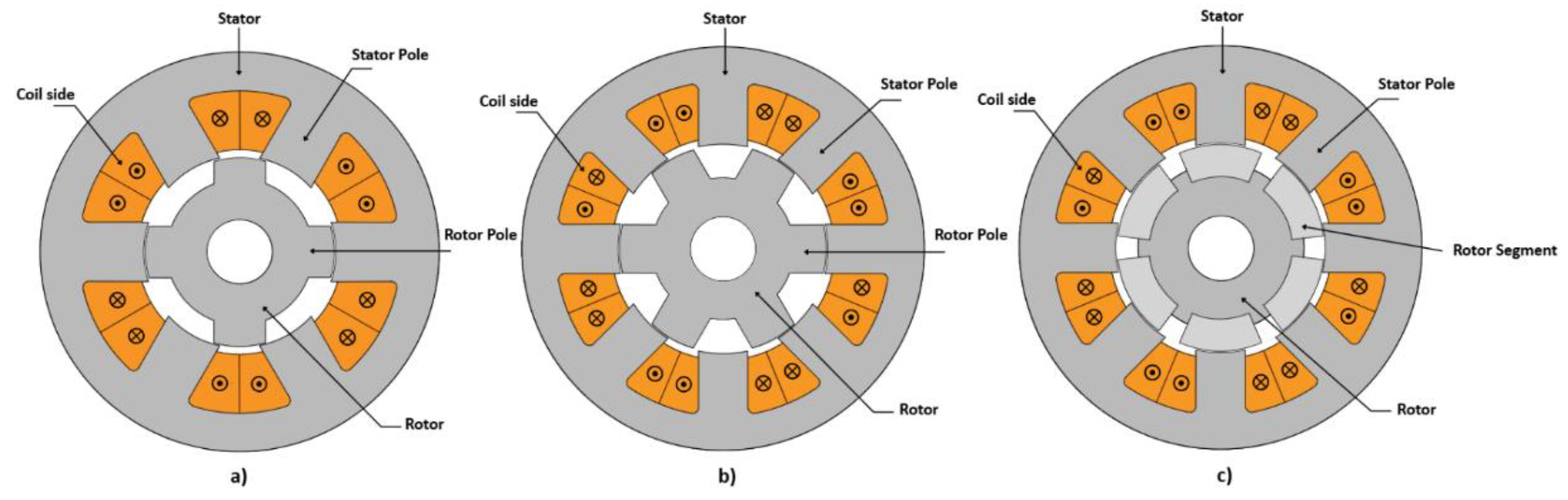
Figure 2.
System-Level Design Optimization Framework.
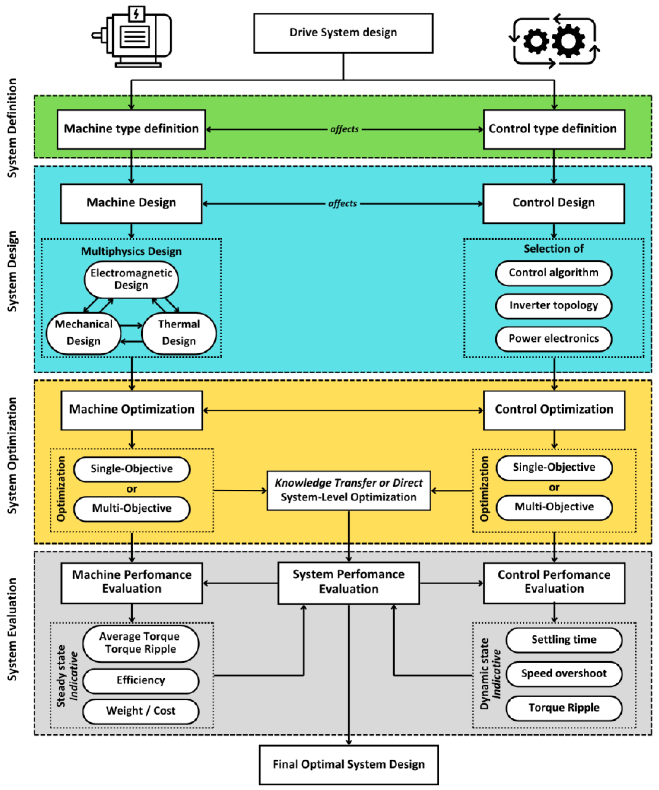
Figure 3.
Single-Level Optimization Framework.
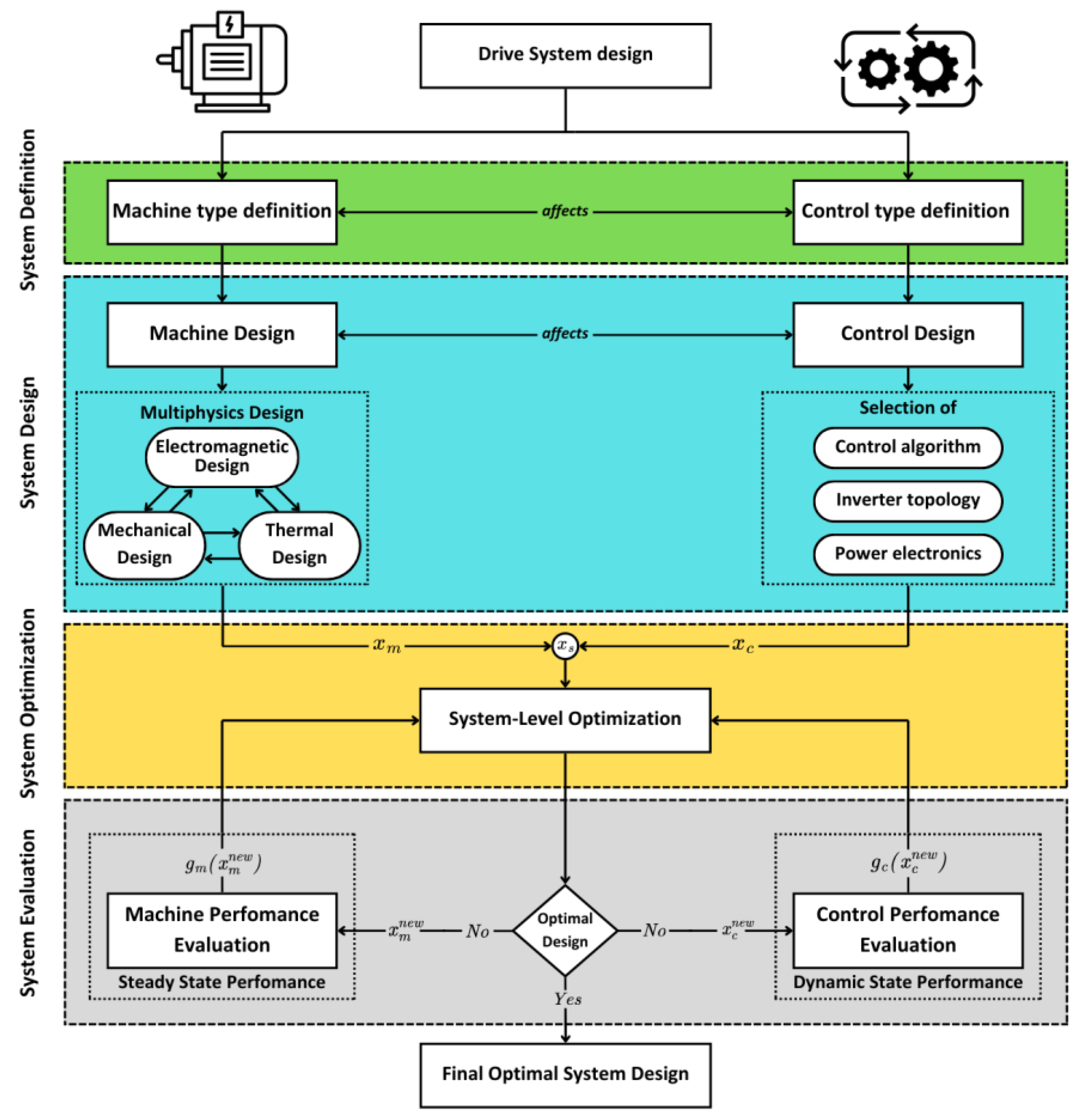
Figure 4.
Multi-Level Optimization Method Framework.
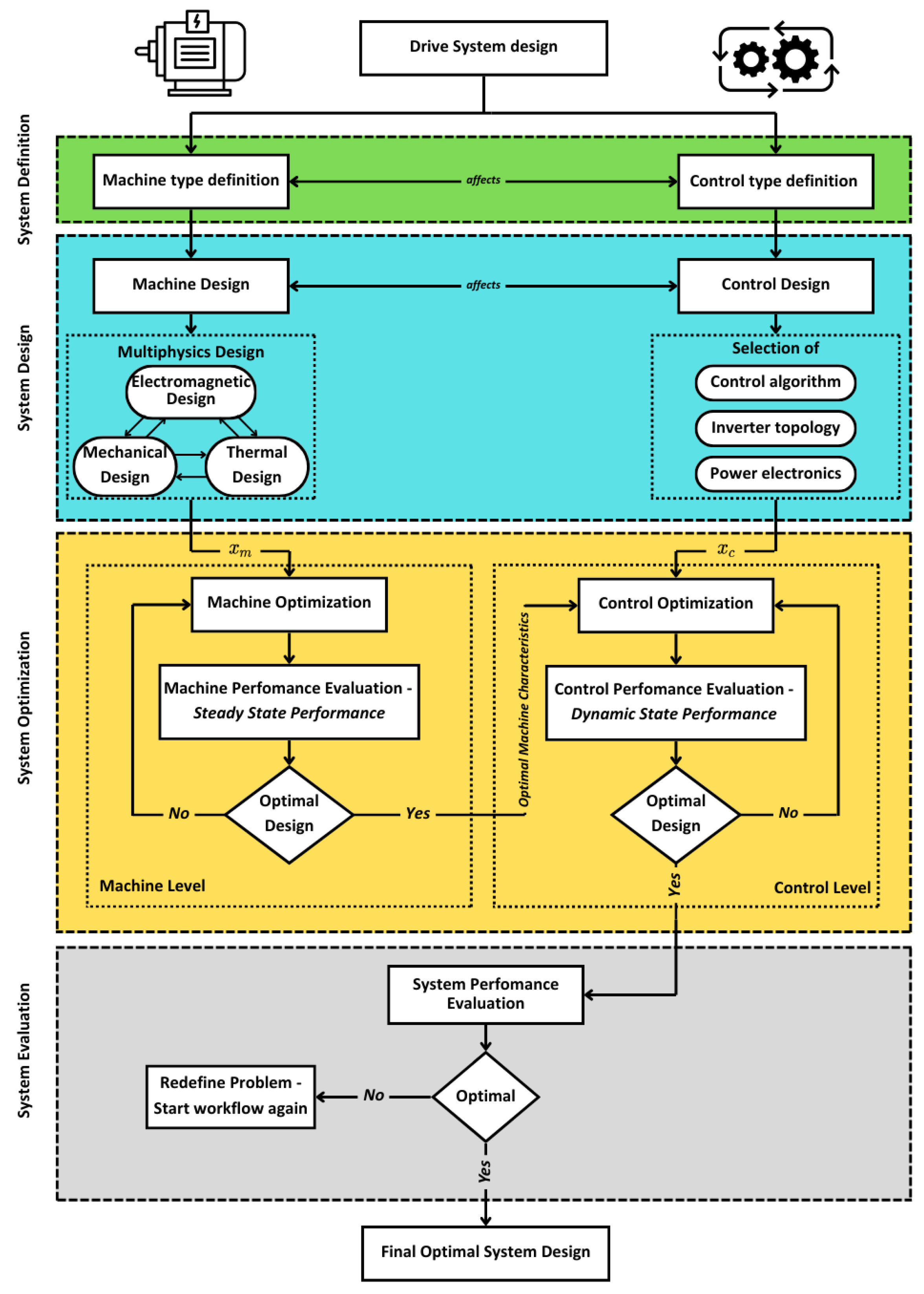
Figure 5.
System-Level techniques and algorithms most commonly employed for reduction of model complexity and search space.
Figure 5.
System-Level techniques and algorithms most commonly employed for reduction of model complexity and search space.
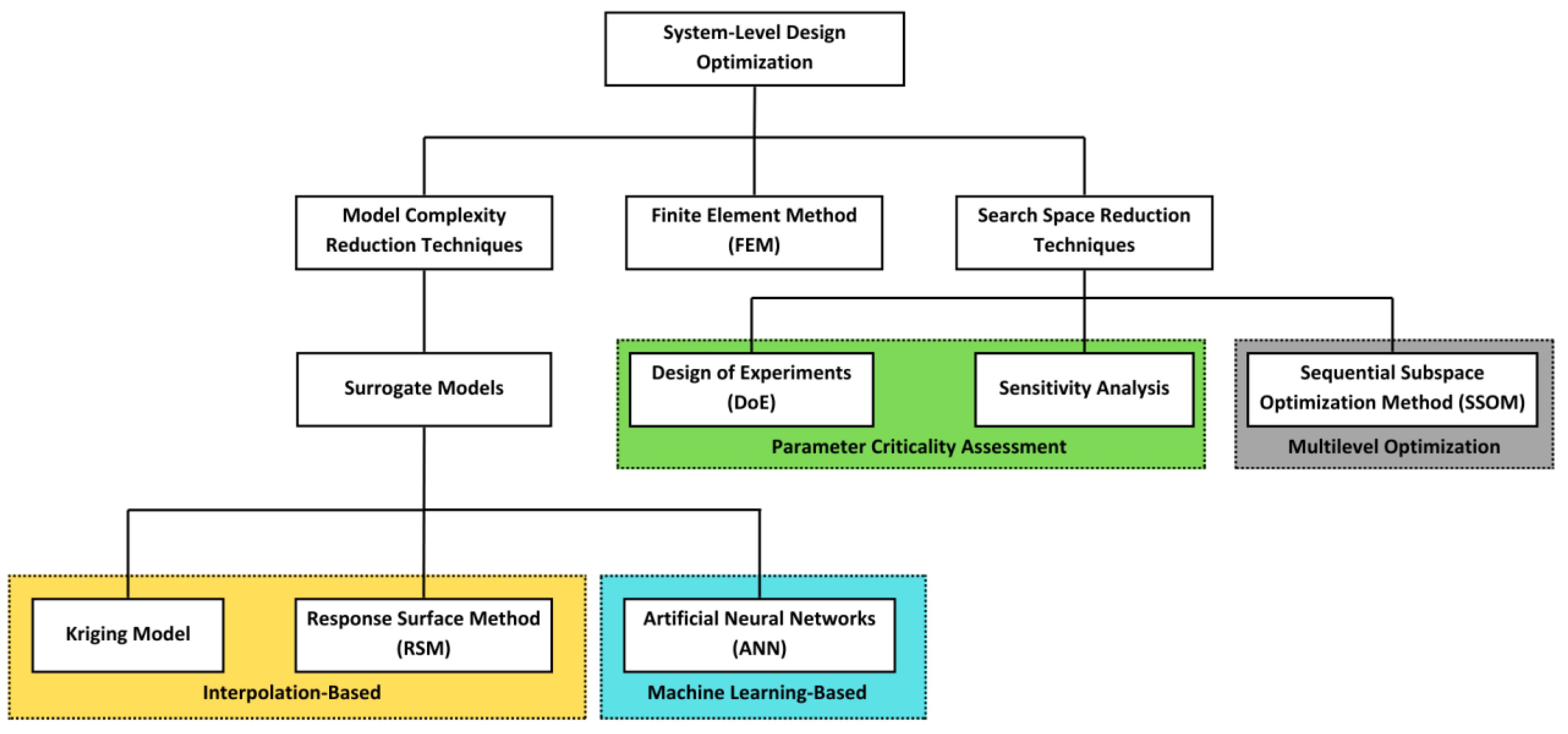
Figure 6.
Illustration of the Kriging model structure and its fundamental components.
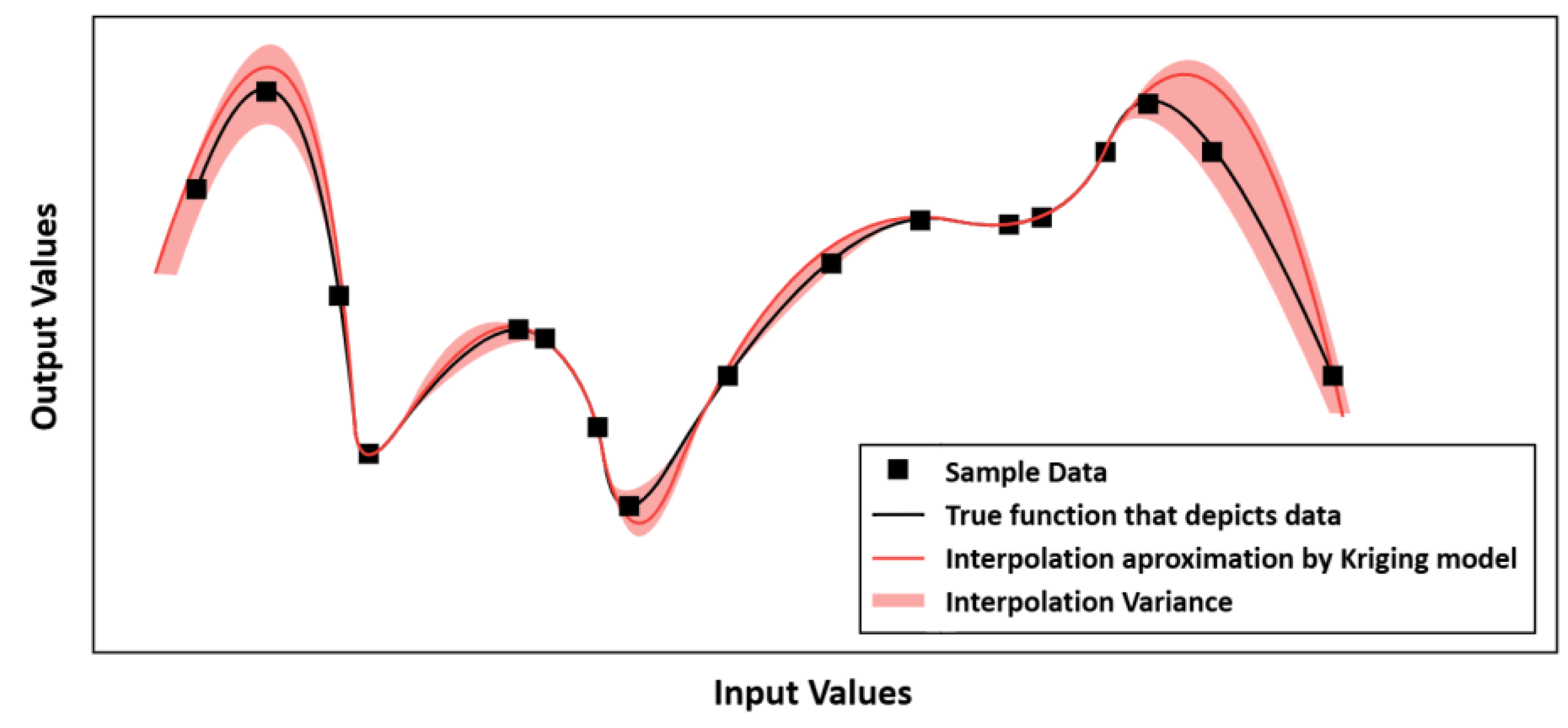
Figure 7.
Torque surface of the Response Surface Method for input rotor position and excitation current.
Figure 7.
Torque surface of the Response Surface Method for input rotor position and excitation current.
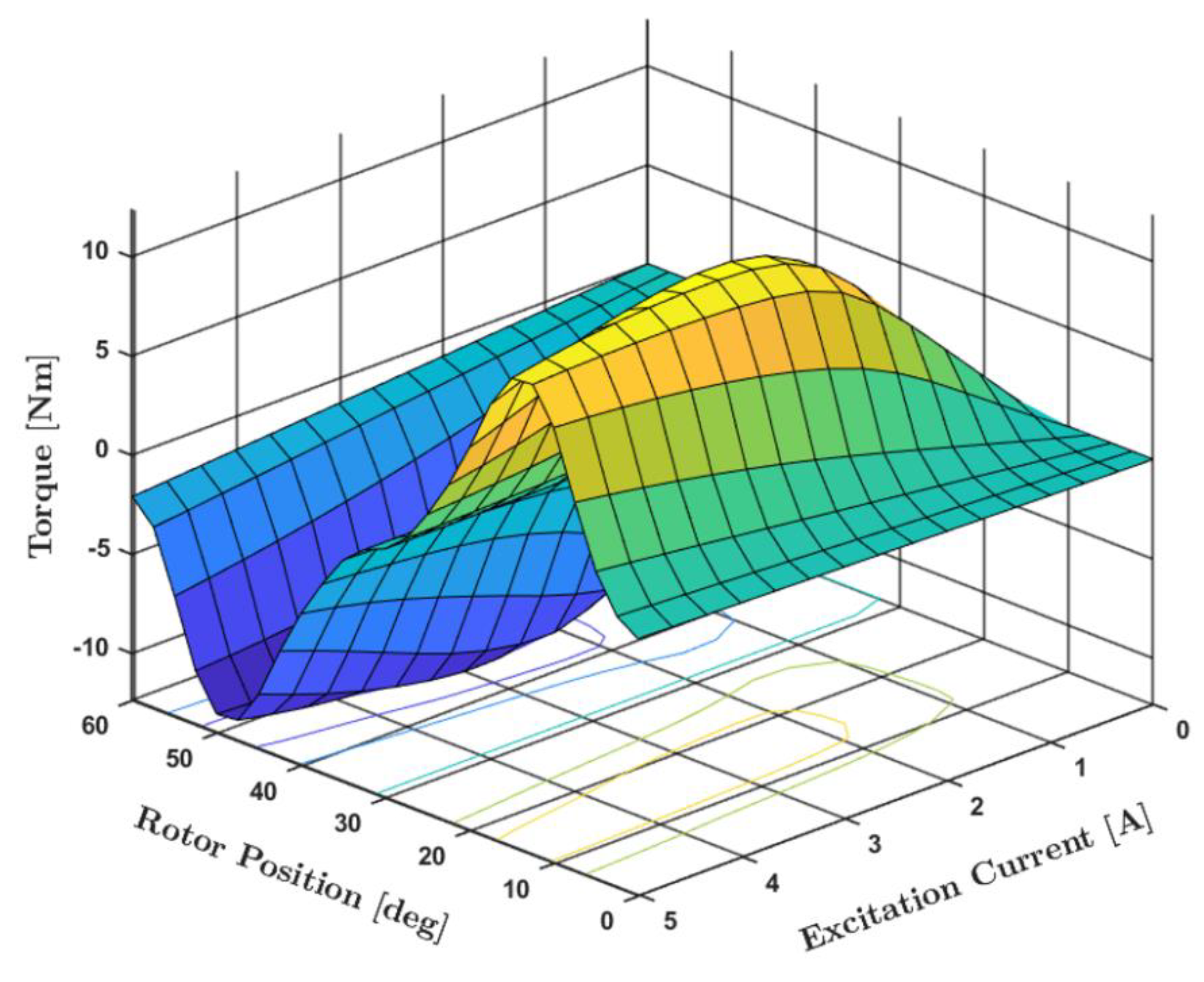
Figure 8.
Basic structure of an artificial neural network. The three primary layers—Input, Hidden, and Output—are illustrated.
Figure 8.
Basic structure of an artificial neural network. The three primary layers—Input, Hidden, and Output—are illustrated.
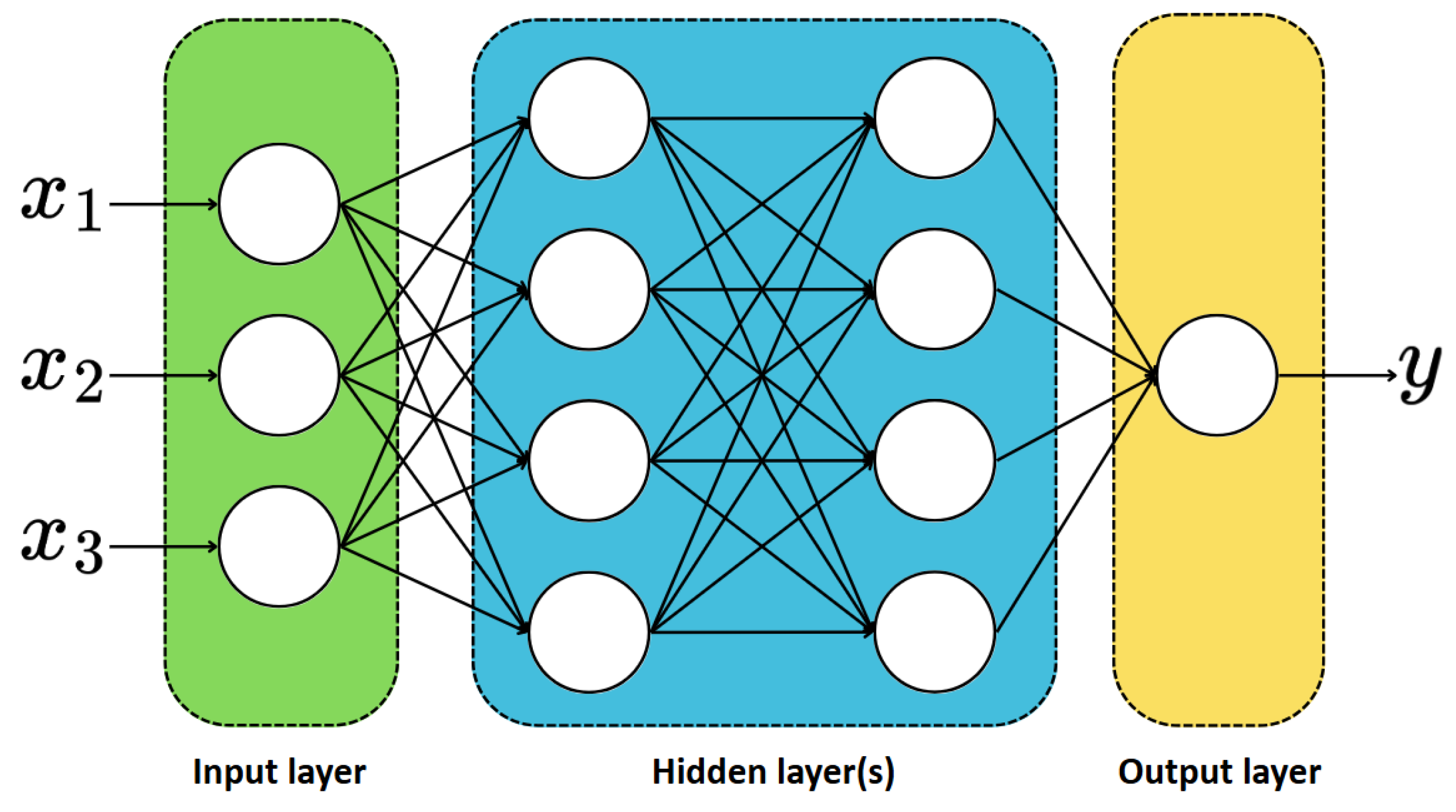
Figure 9.
Sensitivity Analysis of output variables y based on input parameters x.
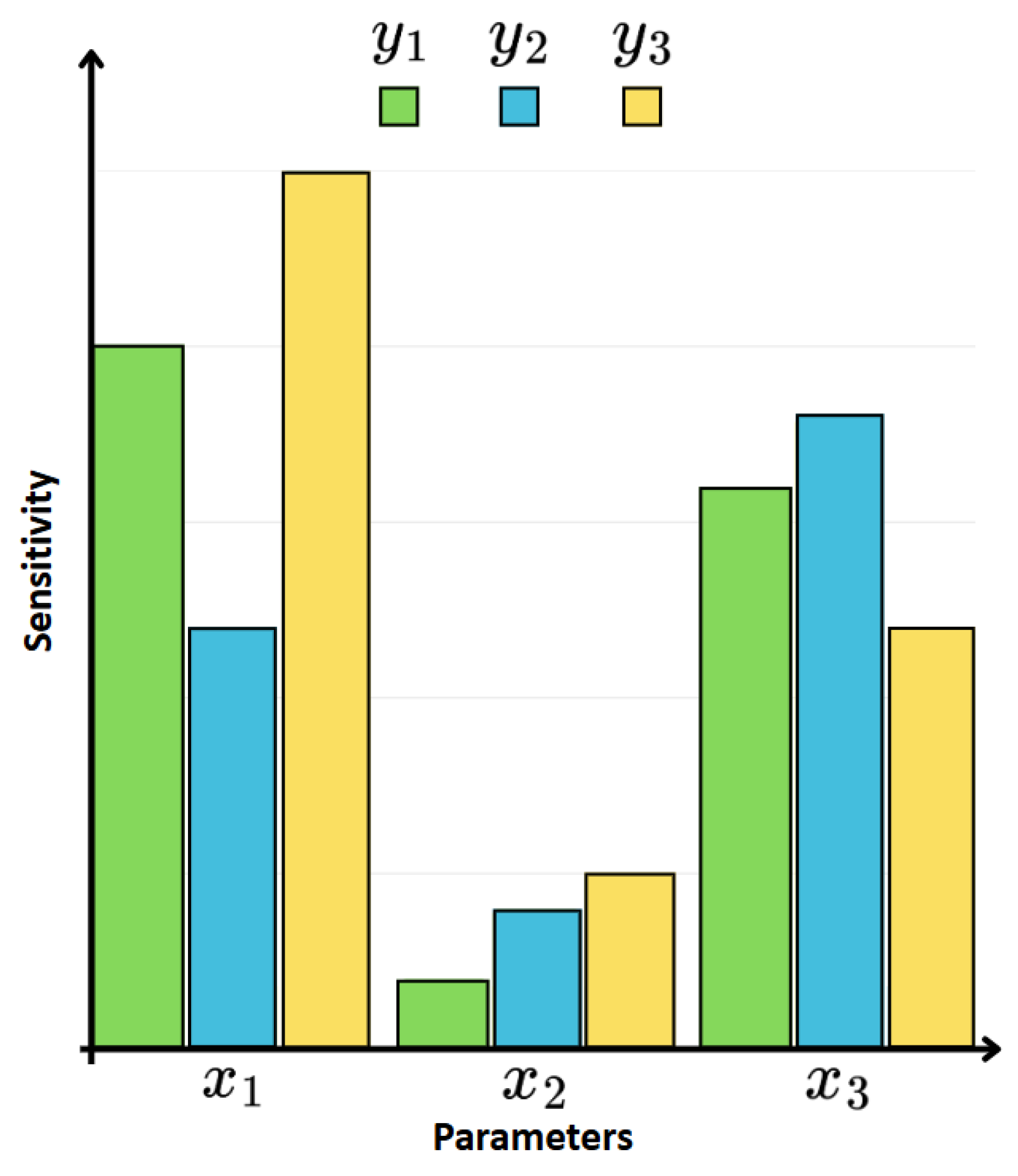
Figure 10.
Sequential Subspace Optimization Method.
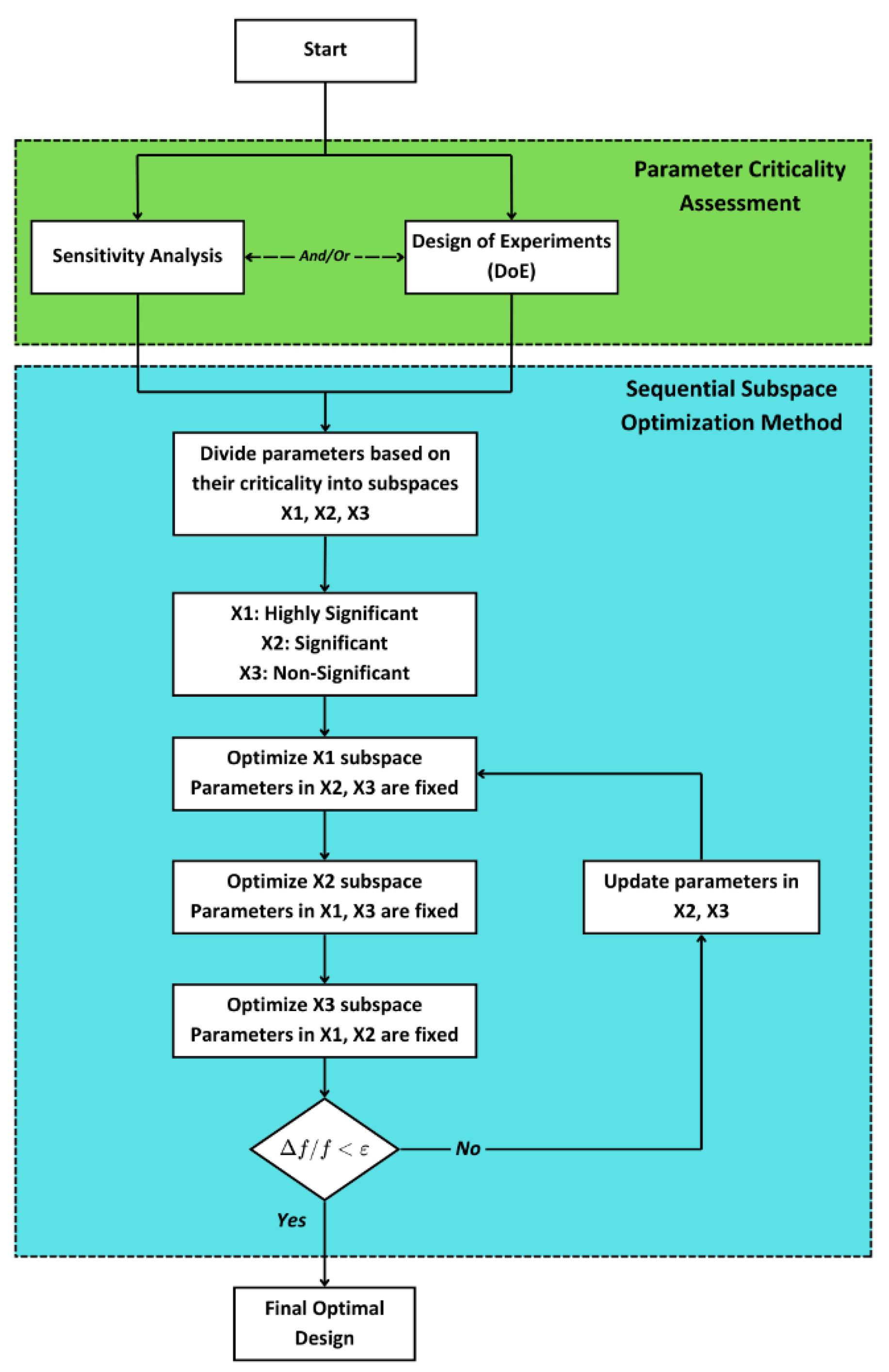
Figure 11.
MPC control strategy integration with Machine Learning modeling for SRM.
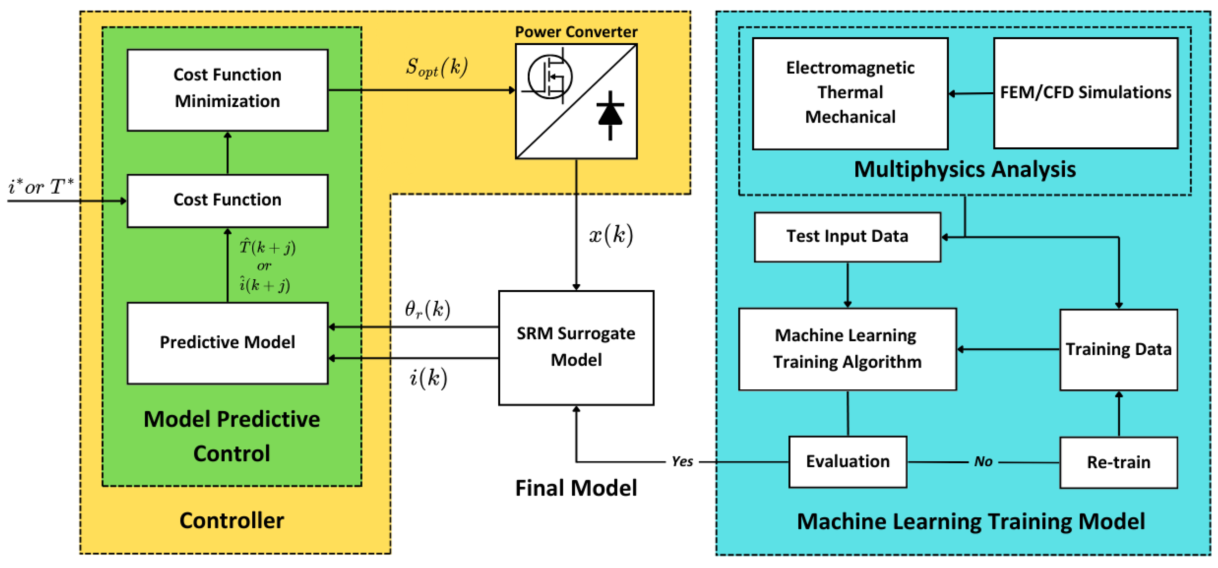
Figure 12.
Implementation of ML-MPC on Single-Level System-Level Design Optimization.
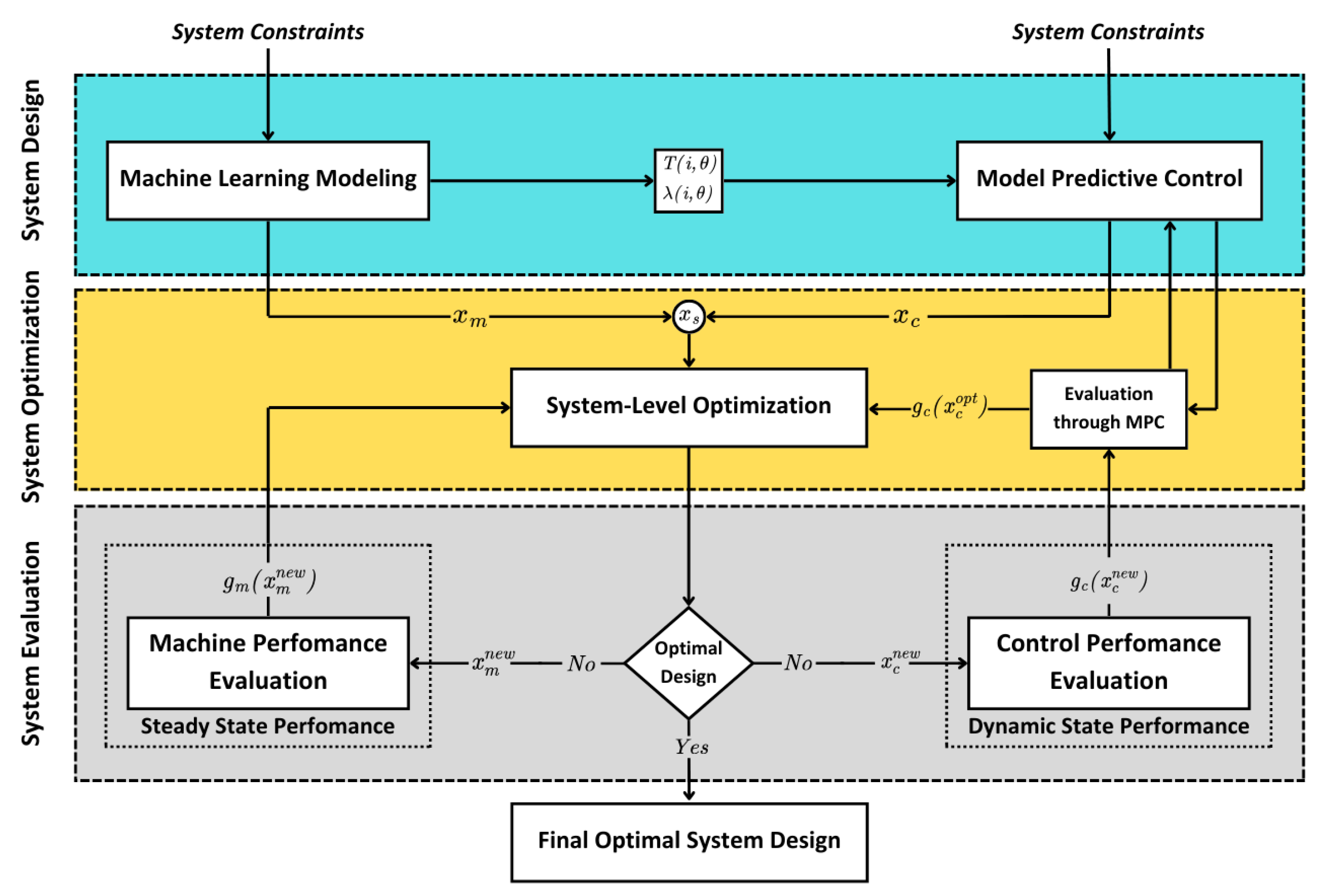
Figure 13.
Implementation of ML-MPC on Multi-Level System-Level Design Optimization.
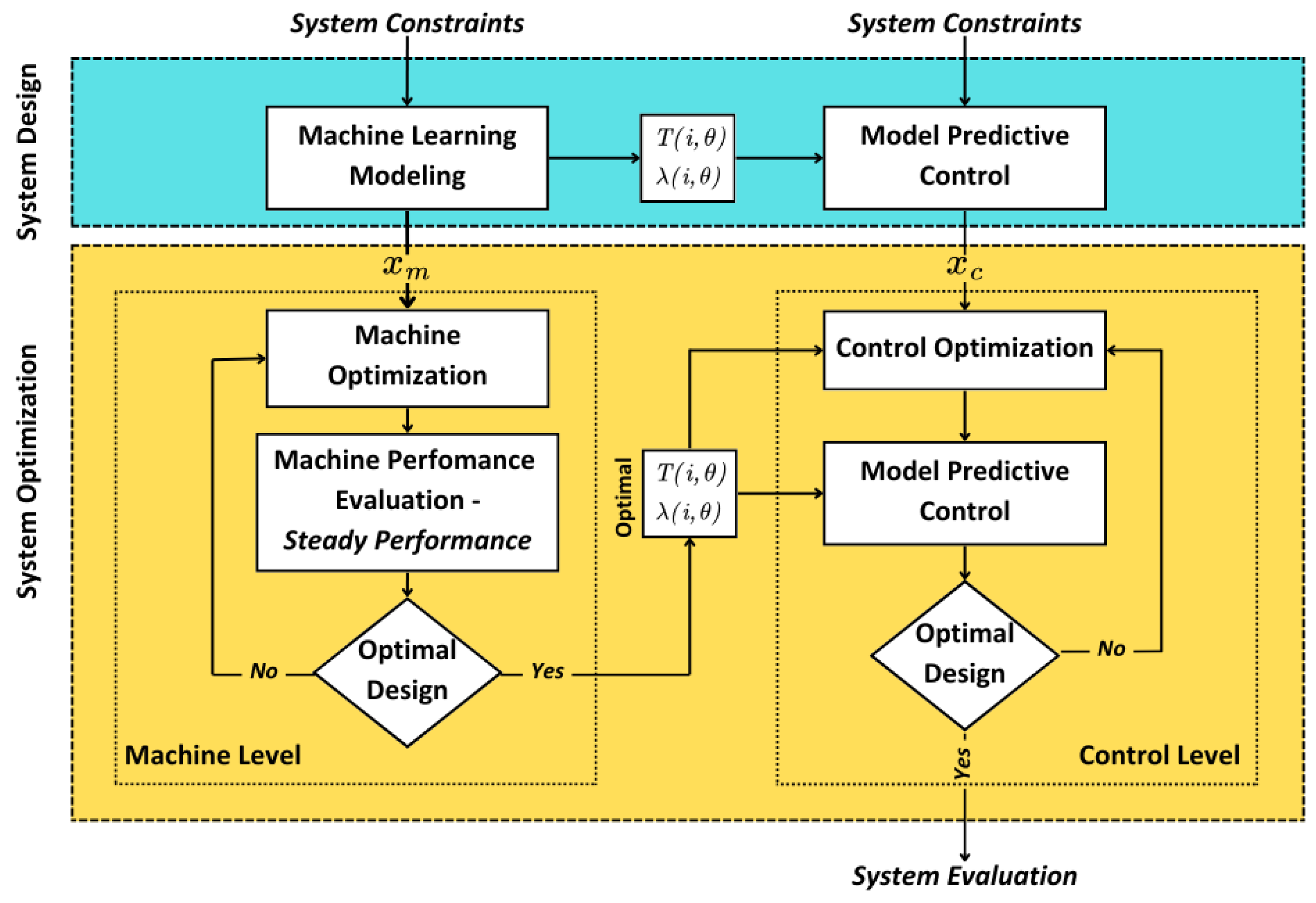
Figure 14.
Deterministic and Robust solutions in optimization problem.
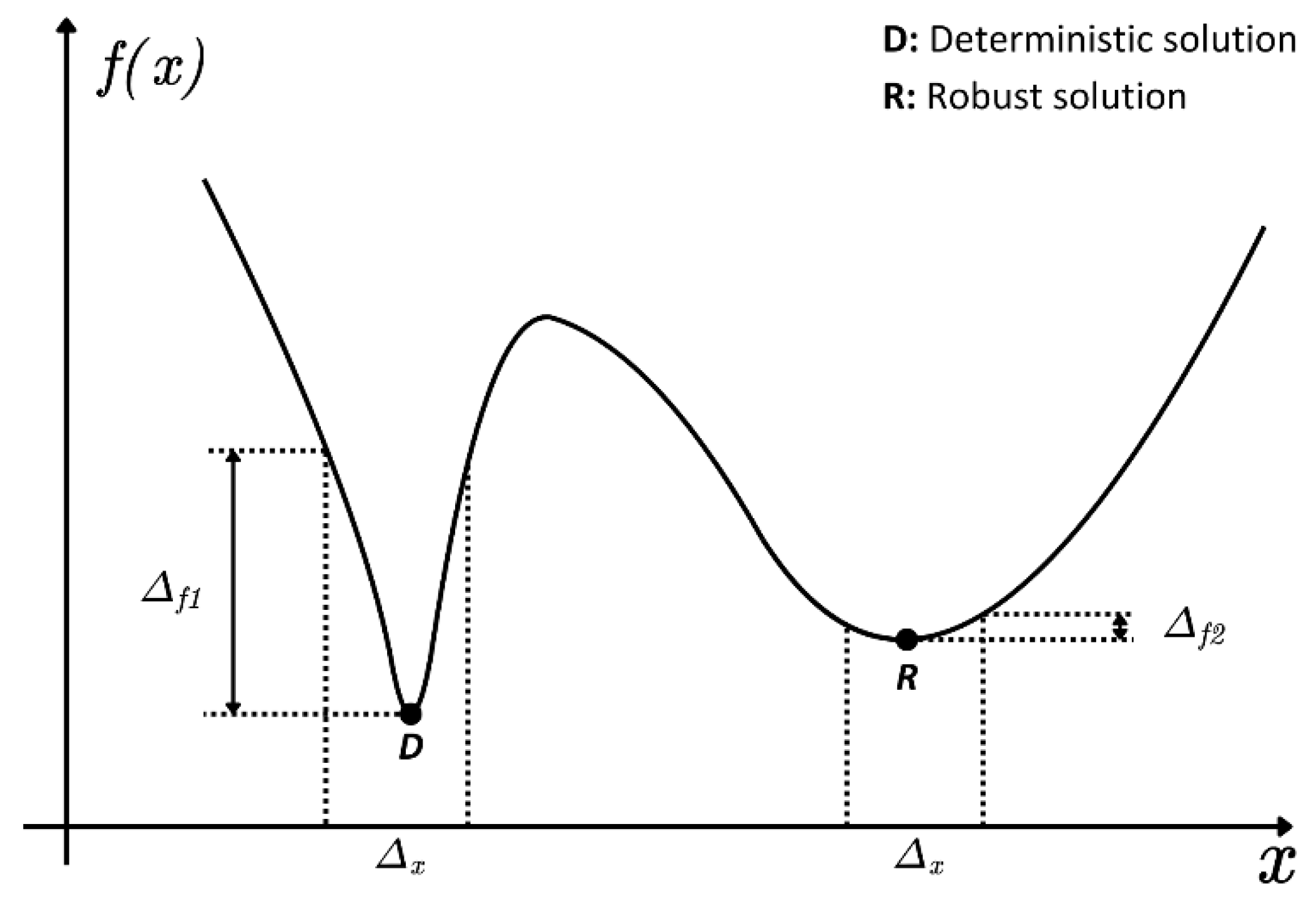

Table 1.
Comparison of surrogate modeling techniques in terms of computational efficiency and accuracy relative to FEM.
Table 1.
Comparison of surrogate modeling techniques in terms of computational efficiency and accuracy relative to FEM.
| Kriging model | RSM | ANN | Models employing SA | Models employing DoE | Models employing SSOM | |
|---|---|---|---|---|---|---|
| Computational time/number of simulations compared to FEM | [30] from 30 min to a few seconds | [43] 559 simulations from 3,000 ones, from 33 hours to roughly 6 | [50] from 900 candidate models to a fraction of them | [54] 33% fewer parameters in simulations | [61] from 15,625 to 25 simulations | [66] from 50,000 to 3,993 simulations (92% reduction) |
| [36] from 100 thousand to 1,125 simulations | [55] from 1-3 mins to 0.5-3 secs | |||||
| [37] from 1,331 to 726 simulations | [62] from 81 to 18 simulations (78% reduction) | |||||
| [38] from 27 million to 1,331 simulations | [56] 90% down in computation time | |||||
| [40] from a few million to a few thousands | ||||||
| Model accuracy compared to FEM | [30] 1-2% discrepancies | [43] almost 100% accuracy | [50] average error 1.5%, maximum error 3% | [54] max 23% overprediction | [61] maximum error 1% | [66] errors well within 1% in the convergence measure |
| [36] decent accuracy | [55] maximum error 2% | |||||
| [37] 1.79% maximum error | [56] maximum error 5% | [62] maximum error 5% | ||||
| [38] average error 1%, maximum error 3.1% |
Table 2.
Summary of references on System-Level Design Optimization of SRMs.
| Ref. | Modeling | Optimization Algorithm | System-Level Algorithm |
Optimization Parameters Machine/Control |
Optimization Goals | Application | ||
| [24] | RSM | FIS - NSGA-III | Single-Level | Geometrical Parameters / θon, θc | Efficiency, Torque Ripple, Power Density | SRG Drives | ||
| [25] | FEM | GA | Candidate Models / θon, θoff | Average Torque, Torque Ripple | Vertical Transportation | |||
| [26] | FEM | PSO | Geometrical Parameters / θon, θoff |
Efficiency, Torque Ripple, Power Density | SRM Drives | |||
| Ref. | Modeling | Optimization Algorithm | System-Level Algorithm | Optimization Parameters Machine/Control |
Optimization Goals | Application | ||
| [27] | Field-Circuit coupled FEM | GA | Single-Level | Geometrical Parameters / θon, θoff |
Efficiency, Mass | Aerospace Applications | ||
| [28,31] | [28] FEM, [31] FEM with SA | [28] NSGA-II, [31] GA | [28] Single-Level, [31] Multi-Level | Average Torque, Torque Ripple, Efficiency | [28] In-Wheel application EV, [31] EV | |||
| [30] | Kriging | NSGA-II | Multi-Level | Average Torque, Torque Density, Losses | EV | |||
| [34] | PR Model | MOGA | Rotor pole shape / θon, θoff |
Average Torque, Torque Ripple | SRM Drives | |||
| [36] | Kriging | NSGA-II | Single-Level | Yoke width ratio / θon, θc |
Average Torque, Torque Ripple, RMS Current | |||
| [37,38,66] | Kriging with SA | [37,38] NSGA-II, [66] SSOM - NSGA-II |
[37] Rotor pole shape, [38,66] Geometrical Parameters / θon, θoff |
Average Torque, Torque Ripple, Losses | ||||
| [39] | Kriging with SA | GRA with TOPSIS | Multi-Level | Geometrical Parameters / θon, θoff |
Average Torque, Torque Ripple, Losses | EV | ||
| [40] | FEM with TLPTM - Kriging with SA | NSGA-II | Single-Level | Average Torque, Torque Ripple, Losses, Temperature Rise | ||||
| [43] | RSM with SA | DE | Torque Ripple, Mass, Copper Losses | In-Wheel application EV | ||||
| [50] | RBFNN with SA | GA, PSO, GRSM | Multi-Level | Candidate Models / θon, θoff | Radial Force Harmonics, Torque Ripple, Average Torque | SRM Drives | ||
| [54] | Analytical Equations with SA | DE | Single-Level | Geometrical Parameters / θon, θoff |
Average Torque, Current Density, Torque Ripple | |||
| [55] | Voltage-fed Analytical Equations and FEM | PSO | Average Torque, Torque Ripple, Efficiency | |||||
| [56], [57] |
FEM with SA | [56] CD-NSGA-II [57] NSGA-II |
[56] Efficiency, Average Torque, [56,57] Torque Ripple |
E-Bikes | ||||
| [61,62] | Taguchi with SA | Taguchi | Average Torque, Torque Ripple, Torque Density | |||||
Disclaimer/Publisher’s Note: The statements, opinions and data contained in all publications are solely those of the individual author(s) and contributor(s) and not of MDPI and/or the editor(s). MDPI and/or the editor(s) disclaim responsibility for any injury to people or property resulting from any ideas, methods, instructions or products referred to in the content. |
© 2025 by the authors. Licensee MDPI, Basel, Switzerland. This article is an open access article distributed under the terms and conditions of the Creative Commons Attribution (CC BY) license (http://creativecommons.org/licenses/by/4.0/).
Copyright: This open access article is published under a Creative Commons CC BY 4.0 license, which permit the free download, distribution, and reuse, provided that the author and preprint are cited in any reuse.


