Submitted:
01 April 2025
Posted:
02 April 2025
You are already at the latest version
Abstract
This study presents a comprehensive analysis of heat transfer processes in double-glazed window systems, employing a approach of experimental measurements and Computational Fluid Dynamics (CFD) simulations, to evaluate the efficacy of shutters in enhancing thermal resistance. The strategic integration of shutters, both internal and external, introduces an additional air cavity, significantly altering the heat transfer dynamics between indoor and outdoor environments. The impact of these configurations on the overall thermal performance of the fenestration system is rigorously quantified through on-site experimental investigations under realistic operational conditions, coupled with numerical solutions of fluid dynamics and energy equations for inter-pane air cavities, and heat conduction equations for solid components. Fourth-kind boundary conditions, incorporating radiative and conductive heat flux contributions from the building's interior, are meticulously applied at solid-gas interfaces. The simulation results demonstrate a substantial 2- to 2.5-fold increase in the thermal resistance of double-glazed units with shutters compared to standard configurations, highlighting their potential as a sustainable material and design strategy for enhancing building energy efficiency. This research contributes to the advancement of sustainable materials for engineering applications by providing insights into the optimization of thermal performance in building envelopes.
Keywords:
double-glazed units
; natural convection
; radiative heat transfer
; thermal resistance
; shutters
; energy efficiency
; sustainable building envelopes
; CFD simulation
; experimental analysis
1. Introduction
The accessibility of window glass for residential and other building construction increased significantly in the late 16th century, leading to its integration into contemporary window sashes [1,2]. Prior to this period, shutters served a multitude of functions now fulfilled by glass, including protection against wind, rain, insects, birds, and intruders. Additionally, shutters were employed for thermal insulation of interior spaces during cold seasons and to mitigate solar radiation ingress during warmer periods.
Glazed windows have since assumed comprehensive protective roles against environmental elements, including thermal insulation. However, fenestration systems remain critical areas of concern in building facades due to substantial specific heat losses in cold climates and excessive heat gains in warm climates. To address these issues, modern fenestration commonly incorporates energy-efficient single, double, and occasionally triple-glazed units. Nevertheless, their thermal resistance remains significantly lower than that of insulated wall elements, underscoring the persistent challenge of enhancing window thermal performance. Research indicates that shutters can substantially reduce heat loss through window assemblies [3,4,5]. A standard double-glazed unit typically exhibits a thermal resistance of approximately Rter=0,35(m2 K/W). The integration of shutters with glazed units can significantly reduce (by 2–3 times) thermal energy loss, particularly at night when solar gains are minimal.
A more precise and comprehensive approach to enhancing window thermal resistance necessitates combined computational and experimental investigations of heat transfer processes through fenestration, analyzing the impact of physical and design factors on heat exchange. These findings are crucial for developing and retrofitting window systems that minimize heat loss and extend operational lifespan without compromising thermal properties. Enhancing window energy efficiency through measures such as shutter implementation can reduce thermal retrofitting costs and improve indoor environmental quality and occupant comfort.
The development of accurate methods for calculating heat transfer through transparent structures is a critical concern, as those currently employed in building thermal physics often rely on parameters that may not fully capture the influence of various factors. These factors include the number of glazing unit chambers, the spacing between glass surfaces, the thermophysical properties of the gaseous medium within these chambers, and the presence of coatings on the glass surfaces designed to reduce radiative heat transfer. When shutters are incorporated, the geometric characteristics of the air cavity between the glazing unit and the shutters must also be considered.
In the studys by [6,7], the focus is on evaluating the thermal resistance of the air cavity specifically between a glazing unit and an external shutter. This works utilizes empirical correlations for the convective heat transfer coefficient, incorporating Rayleigh and Prandtl numbers. The radiative component of heat transfer is calculated using the Stefan-Boltzmann and Kirchhoff laws. However, the conductive component is not considered. The study demonstrates the dependence of the air cavity's thermal resistance on the aspect ratio between the cavity's height (H) and its width (L). Nevertheless, the conclusion regarding the temperature dependence of thermal resistance appears somewhat questionable.
The report [8] presents the results of a study conducted by the Scottish Energy Centre (SEC) at Edinburgh Napier University for the National Trust for Scotland to measure the U-value of two types of glazing insulation: shutters and films. The aim of the study was to determine the benefits of these insulation measures when applied to an existing single glazed window with a binding and box. It was determined that shutters were more effective in improving the thermal insulation properties of existing single glazed windows. Compared to a window without a shutter, the heat transfer resistance of the new design increases by almost 5 times.
The problem of modernising existing window structures in order to increase their heat transfer resistance is addressed in [9,10,11]. Similarly to [9,10] shows that internal panel thermal shutters in the modernisation of existing windows can significantly improve the thermal insulation characteristics of buildings, while maintaining the efficiency of existing glazing in providing natural light. The papers also argues that internal shutters achieve the best thermal performance when air infiltration into the space between the window and the shutter is minimised. This minimises the risk of liquid condensation behind thermal shutters.
The enhancement of thermal resistance in window assemblies through the incorporation of supplementary elements has been extensively investigated [12,13]. These studies share a common methodological approach, employing software tools such as WINDOWS to analyze heat transfer processes between the external environment and the building's interior through window systems equipped with these additional components. In [14], a single-glazed unit with internally installed blinds is examined. The findings reveal that the spacing between the blinds and the glazing significantly impacts the overall heat transfer coefficient (U-value). Considering economic feasibility, the author recommends utilizing double-glazed windows with a 30 mm distance to the blinds. This configuration achieves a U-value of 2.1 W/m2K, corresponding to a thermal resistance (Rterm) of 0.47 m2K/W.
In [15], the applicability of ASHRAE software for simulating heat transfer within complex fenestration systems is examined. This study focuses on the modeling of glazing systems integrated with various shading devices, including shades, blinds, curtains, roller shutters, and insect screens, employing internally mounted blinds as a specific case. The research elucidates inherent limitations within the software, notably a reduction in accuracy when the distance between glazing and shading elements surpasses 10 mm.
Thermal shutters offer a viable solution for significantly reducing heat loss through windows and enhancing the overall energy performance of buildings [16,17,18]. These studies employ computational modeling to investigate the impact of advanced insulation materials, specifically vacuum insulation panels, on improving the thermal characteristics of window assemblies equipped with shutters fabricated from these panels. The results demonstrate a substantial reduction in heat loss through windows when utilizing vacuum insulation panels as internal thermal shutters. Notably, the thermal insulation performance of windows with vacuum insulation panel shutters is shown to be 2.5 times superior to that of the same window without shutters. This improvement is attributed to the relatively large thickness of the vacuum panel (50 mm) and its exceptionally low thermal conductivity (0.005–0.008 W/(m·K)).
A comprehensive review of strategies aimed at enhancing fenestration energy efficiency is presented in [19,20,21,22,23]. These studies systematically evaluate the efficacy of diverse interventions, including curtains, drapes, blinds, screens, and shutters, based on a range of performance metrics. These metrics encompass heat transfer reduction, solar heat gain modulation, daylighting provision, thermal comfort maintenance, condensation risk mitigation, air leakage control, economic feasibility, operational convenience, privacy provision, and aesthetic integration. Utilizing data derived from scholarly literature, manufacturer specifications, and computational tools such as WINDOW and THERM, the review concludes that internal applications of energy efficiency enhancements are predominantly effective in conserving interior thermal energy, while external applications primarily serve to regulate solar radiative influx through building facade apertures.
It is pertinent to note that the majority of prior investigations have predominantly centered on the individual components of window assemblies integrated into building facades. However, the progressive advancement of computational technology has enabled the comprehensive analysis of multifaceted factors and design parameters influencing heat transfer through fenestration systems via Computational Fluid Dynamics (CFD) modeling. This methodology facilitates the numerical solution of equation systems governing fluid dynamics within the air cavities of window assemblies, heat exchange between glazing unit components, and thermal transfer from the window to its ambient environment. Contrary to the assertion in [5], which posits a static air condition within the climatic chamber during single-glazed unit heat transfer experiments, fluid motion in proximity to window assembly components is invariably present. This motion, driven by natural convection, arises from temperature gradients between interior and exterior environments. This observation is corroborated by findings presented in [24,25].
Considering the current state of computational technology, the aforementioned factors can be investigated concurrently through CFD modeling, which numerically solves the equation systems governing fluid dynamics within window assembly air cavities, heat exchange between glazing unit components, and heat transfer from the window to the environment. The fluid motion is primarily driven by natural convection, arising from temperature differentials between the interior and exterior environments.
Shutter designs and materials for their manufacture. Considering the construction of stationary shutters, the following should be distinguished [26]:
- louvred shutters, which are the most common types of shutters; fixed louvres or slats are angled to filter light, provide ventilation and add aesthetic appeal;
- raised panel shutters are stationary shutters that have a classic flat middle part with bevelled edges, which gives the facade rigidity;
- shaker style shutters include a flat component with vertical shallow seams spaced equally apart; this fixed construction can also be known as shaker, country, cottage, frame board and batten or craftsman shutters;
- flat panel shutters are more modern in appearance and are often installed on modern facades to improve the overall aesthetic appearance of the building;
- combined shutters combine the design features and advantages of a louvred shutter and a lift panel;
- board and batten shutters have a simple design and appearance that gives a modern urban building the look of a rural farmhouse;
- bahama shutters are characterized by a design in which each panel is hinged at the top of the window, allowing it to project outward from the bottom; these shutters frequently incorporate multiple horizontal rows of louvers. This architectural feature is predominantly observed in southern regions.
The aforementioned list of shutters primarily encompasses stationary designs, typically installed externally. These stationary shutters are predominantly fabricated from materials such as wood, polyvinyl chloride (PVC), medium-density fiberboard (MDF) composites, vinyl, and other similar substances. In contemporary applications, the term "shutters" also extends to include blinds and roller shutters, or roller blinds. Blinds are primarily utilized for solar radiation control, whereas roller shutters fulfill the comprehensive functions of traditional shutters. The slats or aluminum profiles, which constitute the primary components of roller shutters, are constructed from thin-walled aluminum, often filled with polyurethane foam. Modern external roller shutters represent a more aesthetically pleasing and contemporary alternative to stationary grilles, wooden, and metal shutters. Equipped with user-friendly operating mechanisms, roller shutters can be easily raised, providing occupants with unobstructed views of the external environment at any time.
The primary objective of this study is to comprehensively evaluate and quantify the enhancement of thermal resistance in double-glazed windows through the integration of shutters. This research aims to achieve this by employing a combined methodology of on-site experimental measurements and Computational Fluid Dynamics (CFD) simulations. Specifically, the study seeks to:
- -
- determine the impact of both internal and external shutter placement on the overall heat transfer characteristics of double-glazed window assemblies;
- -
- analyze the fluid dynamics and energy equations within the inter-pane air cavities and the heat conduction within solid components of the window structure under realistic operating conditions;
- -
- quantify the increase in thermal resistance achieved by incorporating shutters, and assess the effectiveness of shutters as a strategy for improving the energy efficiency of windows and building envelopes;
- -
- investigate the influence of various design and physical factors, including the geometric characteristics of the air cavity between the glazing unit and shutters, on the heat transfer processes;
- -
- validate the numerical simulations against experimental data to ensure the accuracy and reliability of the findings;
- -
- provide practical recommendations for the selection and implementation of shutters to optimize thermal performance in both new and retrofitted window systems.
2. Materials and Methods
To examine the intricate heat transfer phenomena occurring within double-glazed windows and integrated blind systems, a comprehensive Computational Fluid Dynamics (CFD) modelling strategy was developed. The overarching aim of this research is to provide a detailed physical understanding of the mechanisms governing heat transfer resistance in these translucent enclosures. Specifically, the methodology involved: formulation of the CFD modelling problem, numerical simulation of airflow and heat transfer and physical substantiation of key factors.
A three-dimensional computational domain, as illustrated in Figure 1, was established for the numerical analyses. The geometric configuration was defined to accurately represent the window structure, including the double-glazed unit and integrated blinds. To provide a clear visualization of the model's internal structure, a cross-sectional plane was defined. This plane, perpendicular to the surfaces of the glass, walls, and blinds, traverses the mid-plane of the insulating glass unit, where the y-coordinate is set to zero.
The geometric model represents a section of an energy-efficient building facade, incorporating a window aperture, as developed at the ITTF of the National Academy of Sciences of Ukraine. The coordinate system origin is positioned at the centroid of the external glass surface (Figure 1). The insulating glass unit frame's three-chamber profile is modelled as a rectangular solid with homogenized material properties, representing PVC, air, and a steel reinforcement bar. The window system features a roller shutter with thin-walled, polyurethane-filled lamellae. Three CFD model variants were generated: external shutter placement at the facade wall level (1), a shutter-free domain (2), and internal shutter placement at the building wall level (3).
2.2. Physical Formulation of the Problem
The physical formulation of the problem concerns the analysis of steady-state thermal transport within a composite system, comprising an indoor air domain maintained at 20 °C, a double-glazed window unit, a three-chamber frame structure, a section of the building facade, and an external ambient air domain at -10 °C. The heat transfer mechanism, driven by the imposed temperature difference, is characterized by the coupled phenomena of convection, conduction, and radiation. Natural convective flows within the air domains result in the formation of hydrodynamic and thermal boundary layers at solid-fluid interfaces. The radiative component of the heat flux accounts for long-wavelength thermal radiation. The momentum and energy transport processes within the system are described by a three-dimensional system of partial differential equations, including the continuity equation, the momentum transport equations (Navier-Stokes), the energy transport equation for the fluid phase, and the Fourier heat conduction equation for the solid phases. The ideal gas equation of state is employed to model the thermodynamic properties of air.
On the solid-air and solid-solid interface surfaces, interface conditions are set that take into account conductive heat exchange between solid surfaces and air, as well as radiative heat exchange between solid surfaces. The above system of equations with limit conditions is solved by numerical method. The method of numerical solution of this problem is discussed in detail in [27,28]. According to the results of the numerical solution of the system of equations, the velocity, pressure and temperature fields in the glass, the air of the window niche and in the gas layers of the insulating glass unit are determined.
2.3. Methodology for Experimental Investigations Under Real-World Meteorological Conditions
Experimental investigations of shutter influence on the thermal resistance of a 4M1i-10-4M1-10-4M1 window assembly with low-emissivity coating were conducted using a multi-layered block of framed panels. These panels consisted of 2.0 mm thick transparent solid polycarbonate and 4.0 mm thick transparent cellular polycarbonate. The panels were installed at varying depths within the window wall opening, both internally and externally. A schematic of the cross-sectional (perpendicular to the facade wall) vertical view of the complete assembly, along with temperature and heat flux sensor locations, is shown in Figure 2.
The experimental procedure involved sequential measurements of various shutter block configurations, with each subsequent measurement incorporating an additional polycarbonate panel. The configurations were as follows: variant 1 – window B (all designations are consistent with Figure 2); variant 2 – window B with shutter C; variant 3 – window B with shutters C and D; variant 4 – window B with shutters C, D, and double-leaf opening shutter E; variant 5 – window B with shutters C, D, E, and F; variant 6 – internal shutter A with window B and shutters C, D, E, and F. Shutters A, C, D, E, and F (A and F being 4.0 mm thick cellular polycarbonate) were installed in a fixed configuration within the opening, with shutter E consisting of two leaves opening outwards.
The polycarbonate panels for shutters C, D, and E were installed with the protective transport films intact. The experimental apparatus utilized a westward-oriented window on the facade of an ITTF experimental passive 'zero-energy' building.
3. Results
3.1. Analysing the Results of Numerical Studies
A comparative study was undertaken to determine the effects of shutters on the heat transfer performance of the fenestration system illustrated in Figure 1, accounting for the influence of adjacent facade components. Analyses were conducted for configurations both with and without shutters, with shutter placement varied between the interior and exterior sides. The resulting velocity and temperature distributions, derived from 3D CFD simulations across vertical planes within the computational domain, are presented in Figure 3 for the three specified scenarios. Furthermore, beyond the standard numerical simulations (V 1, V 3), additional computations were executed for a double-chamber insulating glass unit with the configuration 4M1i-10-4M1-10-4M1 (interior to exterior). This glazing configuration incorporates an i-coating on the inner glass surface, which significantly lowers the surface emissivity to ε=0.2, compared to ε=0.93 for conventional glass. This reduced emissivity effectively mitigates the radiative component of the heat flux emanating from the interior, consequently improving the overall thermal resistance of the window structure.
The airflow visualization presented in Figure 3 reveals that the vertical air velocity profiles within the inter-pane cavities of the double-glazed unit are analogous to those thoroughly documented in [29]. A distinct recirculating flow regime is established within the airspace bounded by the shutters and the double-glazed unit, featuring the development of boundary layers along the respective surfaces. The central portion of this airspace is characterized by a region of stagnant air.
Figure 4a elucidates the temperature distributions across the computational domain's thickness for the three distinct configurations under investigation. To provide a comprehensive understanding of the thermal profiles, temperature data were extracted along a linear trajectory traversing the geometric center of the computational model, extending from the external facade to the interior wall boundary, as depicted in Figure 4b.
The analysis of air circulation velocities within the inter-glass spaces of the insulating glass unit revealed exceptionally low magnitudes (≤ 0.02 m/s). This observation strongly suggests that convective heat transfer plays a negligible role in the overall thermal transport mechanism within these regions. Consequently, the temperature profile across the gas layers of the double-glazed unit manifests a near-linear characteristic (Figure 4a, curve 2), a hallmark signature of a conduction-dominated heat transfer regime. This linearity underscores the dominance of conductive heat transfer over convective contributions within the sealed glass layers.
Furthermore, within the central airspace formed between the shutters and the double-glazed unit, a distinct region of stagnant air characterized by a nearly uniform temperature distribution was observed (Figure 4a, curves 1, 3). This temperature uniformity indicates a lack of significant air movement and, by extension, minimal convective heat transfer within this airspace. The stagnant air effectively acts as an additional insulating layer, contributing to the overall thermal resistance of the system.
The observed temperature profiles, therefore, provide compelling evidence of the dominant role of conduction in heat transfer through the multi-layered glazing system, with minimal contributions from convection, especially within the sealed inter-glass spaces. The stagnant air region between the shutters and the double-glazed unit further enhances the thermal insulation properties of the system, showcasing the importance of air layer configurations in thermal management.
The resulting flow and thermal fields are comparable to those observed in a configuration employing two serially arranged double-glazed units [30], implying that radiative heat transfer is the primary mechanism governing the thermal exchange between the double-glazed unit and the shutters. Figure 5 presents the temperature distribution along vertical lines intersecting the geometric centers of the glass surfaces interfacing with the ambient environment (a) and the room air (b).
The data presented in Figure 5 demonstrate that the implementation of shutters has a profound effect on the temperature distribution profiles across the glass surfaces of the double-glazed unit. Notably, shutters effectively attenuate the temperature gradient across the unit. The average temperature differentials between the external and internal glass surfaces were quantified as follows: ΔT = 5.8 °C for configuration V1, ΔT = 16.5 °C for configuration V2, and ΔT = 7.9 °C for configuration V3. The deployment of external shutters provides a thermal barrier against the exterior environment, resulting in an elevation of temperature on both the external and internal glass surfaces, with both temperatures remaining above zero.
The heat flux magnitude represents a crucial thermophysical parameter for any fenestration system, especially considering the inherent vulnerability of windows as primary conduits for heat loss in building envelopes. Figure 6 and Figure 7 illustrate the heat flux density distributions at the central region of the glass surfaces exposed to the ambient environment. As shown in Figure 6a, the configuration featuring interior shutters (V3) exhibits the lowest heat flux towards the external environment, thereby indicating the most energy-efficient design among the studied cases.
Figure 6b provides a comparative analysis of heat flux density values for configurations V1 and V3, contrasting the results obtained with and without the implementation of an i-coating on the glass surface of the double-glazed unit that is proximate to the interior environment.
It is noteworthy that the application of the i-coating demonstrates a marginal influence on the overall heat loss through the shuttered window assembly. Specifically, for configuration V1, the heat flux density with the i-coating is reduced by approximately 3% on average. For configuration V3, the corresponding reduction is observed to be 14%.
For the unshuttered window assembly depicted in Figure 7, the implementation of an i-coating results in an 11% reduction in heat loss (curve V2i, Figure 7). To provide context, the radiative component of the heat flux density to the ambient environment is presented, revealing that it constitutes over 60% of the total heat loss. The observed oscillations in heat flux density along the vertical line on the external window surface are attributed to the inherent instability of the natural convection boundary layer forming on these surfaces (Figure 8).
An essential metric for assessing the thermal insulation properties of building facade elements, specifically window assemblies, is the thermal resistance. This parameter is quantified through the application of the subsequent computational formula:
Rter = (Tin – Tout)/qout
where Tin represents the temperature of the glass surface interfacing with the indoor environment, Tout denotes the temperature of the glass surface exposed to the outdoor environment, and qout signifies the heat flux density transmitted through the double-glazed unit to the surrounding environment.
Based on the numerical simulations, the thermal resistance was determined for the three considered configurations, including the window assembly with shutters. In the latter case, the exterior shutter surface temperature was used in place of the exterior glass surface temperature in the thermal resistance formula. It is noted that the heat transfer resistance calculations were performed using area-averaged values. Table 1 presents the thermal resistance values for all investigated configurations.
3.2. Results of Experimental Analysis Under Real Meteorological Conditions
The following analysis details the findings of experimental studies performed in authentic meteorological environments, with a particular emphasis on the thermal resistance of diverse window and shutter configurations. Figure 9 provides a visual representation of the experimental setup, featuring a frontal view of the hinged shutter E (Figure 9(a)) and a detailed close-up of the heat flux and temperature sensors affixed to the window assembly (Figure 9 (b)). In the background of (b), sensors of shutter D and the silhouette of shutter C sensors are visible.
A series of graphs depicting experimental data for six distinct window block configurations, incrementally implemented from variant 1 to 6, are presented in Figure 10. Thermal resistance calculations were performed using quasi-steady-state measurements obtained exclusively during nighttime hours, ensuring the absence of insolation and personnel influence. The comprehensive methodology employed for measurement execution and data processing is thoroughly described in [31].
4. Discussion
Contemporary Ukrainian building regulations [32] stipulate a thermal resistance requirement of 0.90 m²K/W for window assemblies. The data presented in Table 2 substantiates that the deployment of four unadorned shutters, equidistantly spaced at approximately 9 cm within the window opening niche, effectively doubles the thermal resistance. This enhancement is achieved through a simplistic and financially prudent methodology. The analysis of the experimental outcomes reveals the following key findings. Shutters demonstrably mitigate building heat losses through facade window niches relative to unshuttered window configurations. The thermal resistance of shuttered systems exhibits a 1.5 to 2-fold augmentation, accompanied by a commensurate reduction in heat flux densities. In all investigated configurations, the inherent thermal resistance of the 4M1-10-4M1-10-4M1 or 4M1i-10-4M1-10-4M1 double-glazed unit remains substantially invariant. The implementation of an i-coating on the glazing substrate precipitates a further amplification of the thermal resistance in shuttered assemblies, culminating in a peak increment of 2 to 2.2 times. The installation of a solitary, stationary shutter panel, fabricated from 2.0 mm thick flat polycarbonate, within the external compartment of the window niche (environmental side) yields an average thermal resistance increment of 15.5 m²K/W.
The maximal increment in thermal resistance is attained when a shutter is deployed within the interior environment, co-planar with the internal wall surface, resulting in an augmentation approaching 50 m²K/W. The enhancement of thermal resistance in window assemblies equipped with shutters, coupled with the corresponding reduction in heat losses, is a direct consequence of the air interlayer formed between the shutters and the glazing. Consequently, the incorporation of shutters, irrespective of their placement, markedly improves the energy performance of the window assembly and the overall building.
5. Conclusions
This study investigated the impact of external shutters on the thermal resistance of window assemblies under real meteorological conditions. Through a combination of numerical simulations and experimental measurements, the research demonstrated the significant potential of shutters to enhance the energy efficiency of buildings. The incorporation of external shutters substantially increased the thermal resistance of window assemblies. Experimental data revealed a 1.5 to 2-fold increase in thermal resistance compared to unshuttered windows, accompanied by a corresponding reduction in heat flux densities. The number and placement of shutters significantly influenced the overall thermal performance. Notably, the introduction of four shutters, strategically positioned within the window opening niche, nearly doubled the thermal resistance. Furthermore, internal placement of the shutter resulted in the highest increment of thermal resistance. The utilization of low-emissivity (i-coating) glass in conjunction with shutters further amplified the thermal resistance, achieving a maximum increase of 2 to 2.2 times. This highlights the effect of combining advanced glazing technologies with passive shading strategies. The improved thermal performance of shuttered window assemblies is attributed to the formation of an insulating air gap between the shutters and the glazing. This air gap effectively reduces conductive and convective heat transfer, thereby enhancing the overall thermal resistance. The findings of this study underscore the practical benefits of implementing external shutters as a cost-effective strategy to improve the energy efficiency of buildings. The straightforward installation and minimal financial investment associated with shutters make them a viable solution for both new and existing constructions.
Author Contributions
Conceptualization, B.B. and V.N.; methodology, A.P.; software, S.G.; validation, A.S., D.D. and H.K.; formal analysis, H.K.; investigation, D.D.; resources, H.K. and A.P.; data curation, D.D.; writing—original draft preparation, V.N.; writing—review and editing, H.K.; visualization, A.P. and H.K.; supervision, H.K.; project administration, H.K.;
Funding
This research received no external funding.
Conflicts of Interest
The authors declare no conflicts of interest.
References
- Insulatingshutters. https://www.designingbuildings.co.uk/wiki/Insulating_shutters.
- Shen, L.; He, B.; Jiao, L.; Song, X.; Zhang, X. Research on the development of main policy instruments for improving building energy-efficiency. J. Clean. Prod. 2016, 112, 1789–1803. [CrossRef]
- Abdullah, A.K.; Darsaleh, A.; Abdelbaqi, S.; Khoukhi, M. Thermal Performance Evaluation of Window Shutters for Residential Buildings: A Case Study of Abu Dhabi, UAE. Energies 2022, 15, 5858. [CrossRef]
- Tiago Silva, Romeu Vicente, Cláudia Amaral, António Figueiredo, Thermal performance of a window shutter containing PCM: Numerical validation and experimental analysis, Applied Energy, Volume 179, 2016, Pages 64-84, . [CrossRef]
- Maria Malvoni, Cristina Baglivo, Paolo Maria Congedo, Domenico Laforgia,CFD modeling to evaluate the thermal performances of window frames in accordance with the ISO 10077, Energy, Volume 111, 2016, Pages 430-438. [CrossRef]
- Ficker T. Heat Losses of Window Compact Shutters. IOP Conf. Series: Materials Science and Engineering 960 (2020) 022021 IOP Publishing. [CrossRef]
- Radl, J., & Kaiser, J. (2019). Benefits of Implementation of Common Data Environment (CDE) into Construction Projects. IOP Conference Series: Materials Science and Engineering, 471. [CrossRef]
- Currie J., Williamson J.B., Stinson J., Jonnard M. Thermal assessment of internal shutters and window film applied to traditional single glazed sash and case windows. Historic Scotland Technical Paper 23. 2014. www.historic-scotland.gov.uk/technicalpapers.
- Hashemi A. and Gage S. (2014). Technical issues that affect the use of retrofit panel thermal shutters in commercial buildings. Building Services Engineering Research and Technology, 35 (1): 6-22. (DOI: 10.1177/0143624412462906).
- M. Che-Pan, E. Simá, A. Ávila-Hernández, J. Uriarte-Flores, R. Vargas-López, Thermal performance of a window shutter with a phase change material as a passive system for buildings in warm and cold climates of México, Energy and Buildings, Volume 281, 2023, 112775, . [CrossRef]
- Rolains Golchimard Elenga, Li Zhu, Steivan Defilla, Performance evaluation of different building envelopes integrated with phase change materials in tropical climates, Energy and Built Environment, Volume 6, Issue 2, 2025, Pages 332-346. [CrossRef]
- Kumar V, Sharda A. An Empirical Study of Thermal Transmittance through Windows with Interior Blinds. J Adv Res Mech Engi Tech 2017; 4(1&2): 10-16.
- Chaoen Li, Hang Yu, Yuan Song, Yin Tang, Pengda Chen, Huixin Hu, Meng Wang, Zhiyuan Liu, Experimental thermal performance of wallboard with hybrid microencapsulated phase change materials for building application, Journal of Building Engineering, Volume 28, 2020, 101051. [CrossRef]
- Foroushani Mohaddes S.S., Wright J.L., Naylor D., Collins M.R. Assessing Convective Heat Transfer Coefficients Associated with Indoor Shading Attachments Using a New Technique Based on Computational Fluid Dynamics. © 2015 ASHRAE (www.ashrae.org). Published in ASHRAE Conference Papers, Winter Conference, Chicago, IL. For personal use only.
- Takada, K., Hayama, H., Mori, T., & Kikuta, K. (2020). Thermal insulated PVC windows for residential buildings: feasibility of insulation performance improvement by various elemental technologies. Journal of Asian Architecture and Building Engineering, 20(3), 340–355. [CrossRef]
- Hashemi A., Alam M., Kenneth Ip. Comparative performance analysis of Vacuum Insulation Panels in thermal window shutters. Technologies and Materials for Renewable Energy, Environment and Sustainability, TMREES18, 19–21 September 2018, Athens, Greece. Energy Procedia 157 (2019) 837–843. This is an open access article under the CC BY-NC-ND license (https://creativecommons.org/licenses/by-nc-nd/4.0/).
- Hashemi A, Gage S. Technical issues that affect the use of retrofit panel thermal shutters in commercial buildings. Building Services Engineering Research & Technology. 2012;35(1):6-22. [CrossRef]
- Ákos Lakatos, Zsolt Kovács, Comparison of thermal insulation performance of vacuum insulation panels with EPS protection layers measured with different methods, Energy and Buildings, Volume 236, 2021, 110771. [CrossRef]
- Hashemi A., Alam M., Mohareb E. Thermal Performance of Vacuum Insulated Window Shutter Systems. ZEMCH, International Conference l Seoul, Korea November 2019.
- Ariosto T., Memari A. M. Evaluation of Residential Window Retrofit Solutions for Energy Efficiency. The Pennsylvania Housing Research Center (PHRC). PHRC Research Series Report No. 111 The Pennsylvania Housing Research Center. December 2013.
- Jonathan Dahl Jørgensen, Jens Henrik Nielsen, Luisa Giuliani, Thermal resistance of framed windows: Experimental study on the influence of frame shading width, Safety Science,Volume 149, 2022, 105683, . [CrossRef]
- Agnieszka A. Lechowska, Jacek A. Schnotale, Giorgio Baldinelli, Window frame thermal transmittance improvements without frame geometry variations: An experimentally validated CFD analysis, Energy and Buildings, Volume 145, 2017, Pages 188-199. [CrossRef]
- Park, S.; Song, S.-Y. Evaluation of Alternatives for Improving the Thermal Resistance of Window Glazing Edges. Energies 2019, 12, 244. [CrossRef]
- Jørgensen, Jonathan Dahl, Jens Henrik Nielsen, and Luisa Giuliani. "Thermal resistance of framed windows: Experimental study on the influence of frame shading width." Safety Science 149 (2022): 105683. [CrossRef]
- Wei, L.; Li, G.; Ruan, S.-T.; Qi, H. Dynamic coupled heat transfer and energy conservation performance of multilayer glazing window filled with phase change material in summer day. J. Energy Storage 2022, 49, 104183. [CrossRef]
- Find the perfect shutters for your home. https://www.shutterland.com/.
- Basok, B.I.; Nakorchevskii, A.I.; Goncharuk, S.M.; Kuzhel, L.N. Experimental Investigations of Heat Transfer Through Multiple Glass Units with Account for the Action of Exterior Factors. J. Eng. Phys. Thermophys. 2017, 90, 88.
- Basok, B.I.; Davydenko, B.V.; Isaev, S.A.; Goncharuk, S.M.; Kuzhel, L.N. NumericalModelingofHeatTransferThrough a Triple-PaneWindow. J. Eng. Phys. Thermophys. 2016, 89, 1277.
- Hanna Koshlak, Borys Basok, Borys Davydenko. HeatTransfer through Double-Chamber Glass Unit with Low-Emission Coating. Energies 2024, 17, 1100. [CrossRef]
- Basok B., Davydenko B., Pavlenko A., Novikov V., Goncharuk S. Heat Transfer Characteristics of Combination of Two Double-chamber Windows. RocznikOchronaŚrodowiska. 2023. Vol. 25. Pp. 289-300.
- Basok B, Novikov V, Pavlenko A, Davydenko B, Koshlak H, Goncharuk S, Lysenko O. CFD Simulation of Heat Transfer Through a Window Frame. Rocznik Ochrona Środowiska. 2024; 26. [CrossRef]
- ISO 10211:2017. Thermal Bridges in Building Construction—Heat Flows and Surface Temperatures—Detailed Calculations; International Standard Organization: Geneva, Switzerland, 2017.
Figure 1.
Representation of the computational model: (a) Three-dimensional geometric domain illustrating the window system, featuring: 1 – double-chamber glass unit 4M1-10-4M1-10-4M1 (1.06×0.642 m), 2 – external air (Tout = -10 °C), 3 – brick wall (0.38 m), 4 – basalt thermal insulation (0.34 m), 5 – internal air (Tin = 20 °C), 6 – three-chamber frame (0.04×0.06 m), 7 – polyurethane foam (0.01 m), 8 – polyurethane shutter (0.01 m), 9 – air layer between glass and shutter; (b) Cross-sectional view of the computational grid, containing in excess of 1025000 cells.
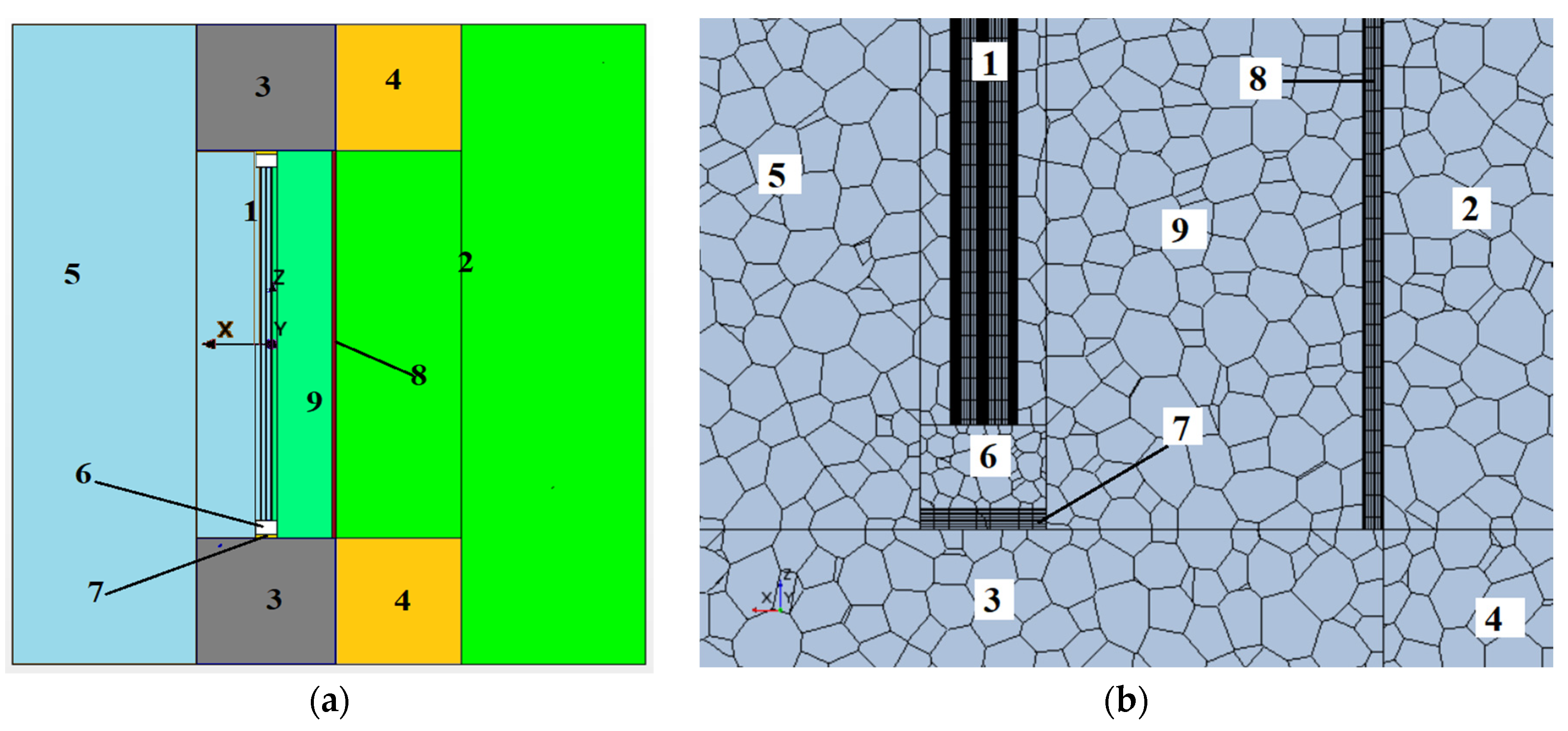
Figure 2.
Schematic diagram of the window block: window opening with dual niches (internal and external) + window + shutter system with sensor locations. Designations: B – double-chamber window, A, C, D, F – stationary shutters, E – double-leaf opening shutter.
Figure 2.
Schematic diagram of the window block: window opening with dual niches (internal and external) + window + shutter system with sensor locations. Designations: B – double-chamber window, A, C, D, F – stationary shutters, E – double-leaf opening shutter.
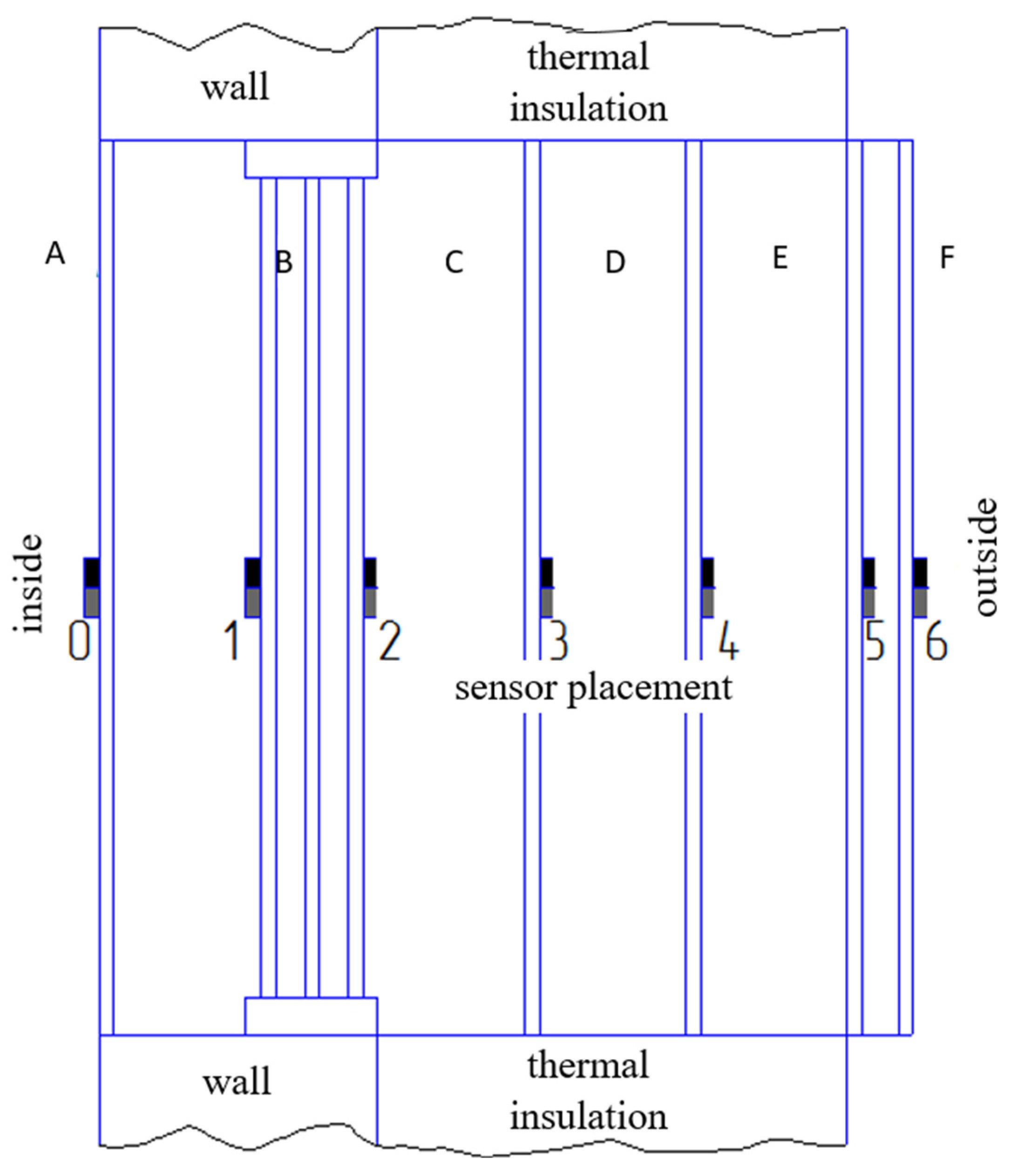
Figure 3.
Numerical results depicting temperature and velocity distributions for the analyzed scenarios: V 1 – exterior shutters integrated at the facade wall plane; V 2 – baseline window configuration without shutters; V 3 – interior shutters situated at the room wall interface.
Figure 3.
Numerical results depicting temperature and velocity distributions for the analyzed scenarios: V 1 – exterior shutters integrated at the facade wall plane; V 2 – baseline window configuration without shutters; V 3 – interior shutters situated at the room wall interface.

Figure 4.
Window assembly temperature profiles: (a) Temperature distributions along the thickness of the window assembly: 1 – configuration with external shutters; 2 – configuration without shutters; 3 – configuration with internal shutters; (b) Spatial location of the line used for temperature profile extraction.

Figure 5.
Temperature distribution along the vertical centerline of glass surfaces: (a) exterior surface, (b) interior surface. V1, V2, and V3 correspond to the modeling scenarios presented in Figure 2; i - cases with an i-coating on the interior glass surface.
Figure 5.
Temperature distribution along the vertical centerline of glass surfaces: (a) exterior surface, (b) interior surface. V1, V2, and V3 correspond to the modeling scenarios presented in Figure 2; i - cases with an i-coating on the interior glass surface.

Figure 6.
Heat flux density at the central region of external glass surfaces: (a) for various window configurations; (b) comparison of heat flux for window assemblies with and without i-coating.
Figure 6.
Heat flux density at the central region of external glass surfaces: (a) for various window configurations; (b) comparison of heat flux for window assemblies with and without i-coating.
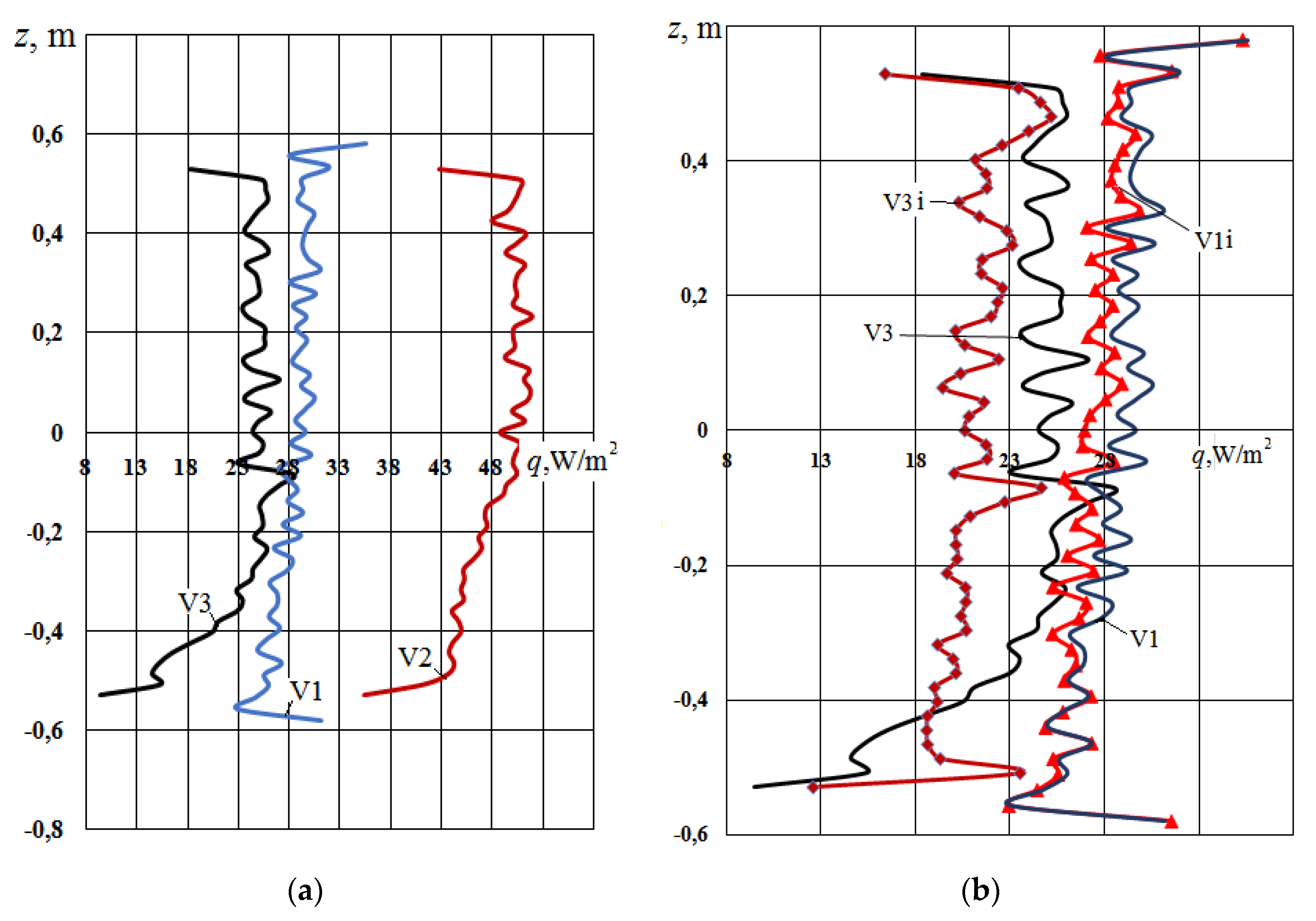
Figure 7.
Heat flux density at the central region of the external surface of the unshuttered window assembly: V2 – heat flux density of a standard double-glazed unit; V2i – double-glazed unit with an i-coating on one glass pane; V2R – radiative heat flux density of the standard double-glazed unit.
Figure 7.
Heat flux density at the central region of the external surface of the unshuttered window assembly: V2 – heat flux density of a standard double-glazed unit; V2i – double-glazed unit with an i-coating on one glass pane; V2R – radiative heat flux density of the standard double-glazed unit.
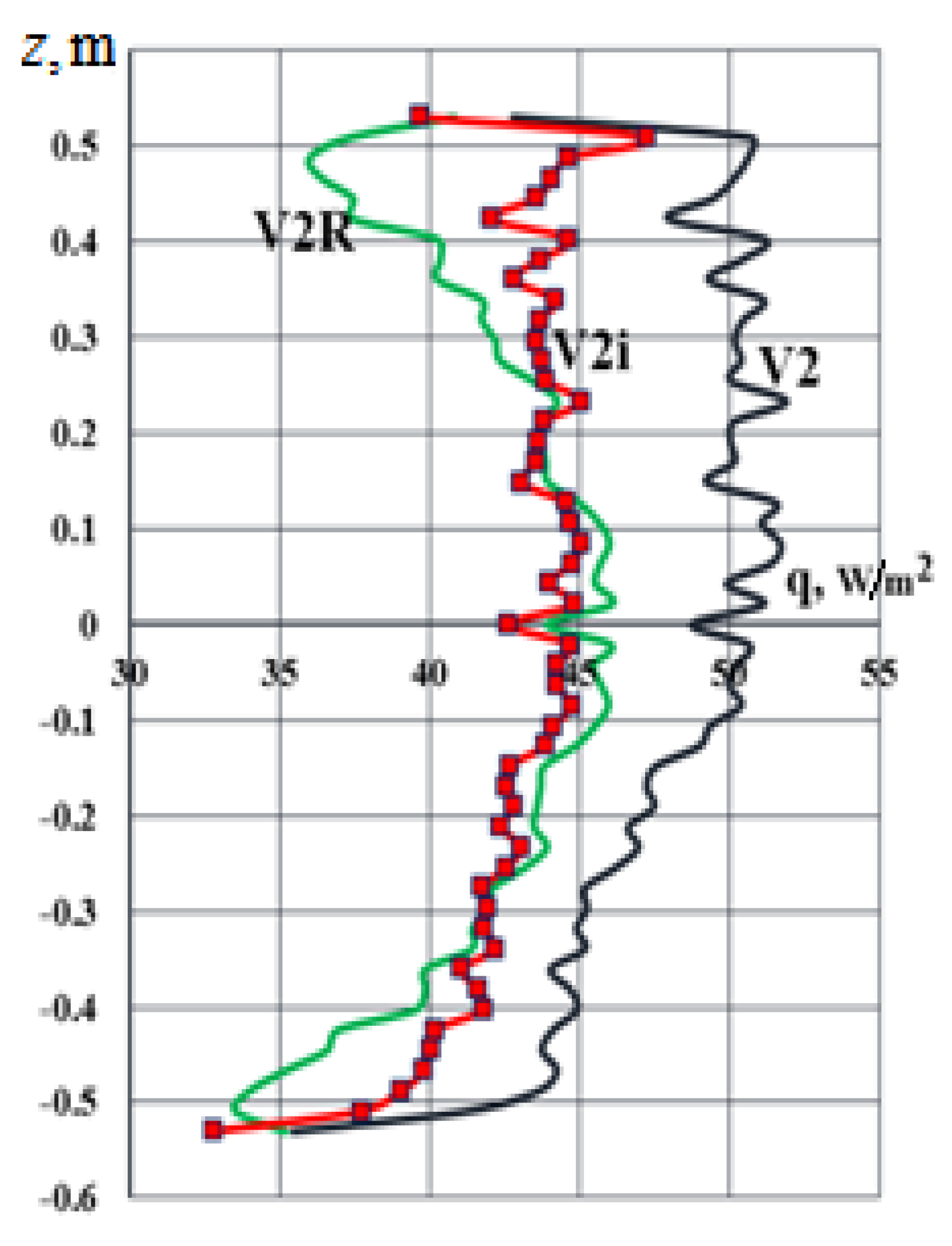
Figure 8.
Air velocity field in the window assembly with external shutters: (a) Unstable boundary layer on air-contacting surfaces; (b) Enlarged detail from Figure 8a.
Figure 8.
Air velocity field in the window assembly with external shutters: (a) Unstable boundary layer on air-contacting surfaces; (b) Enlarged detail from Figure 8a.
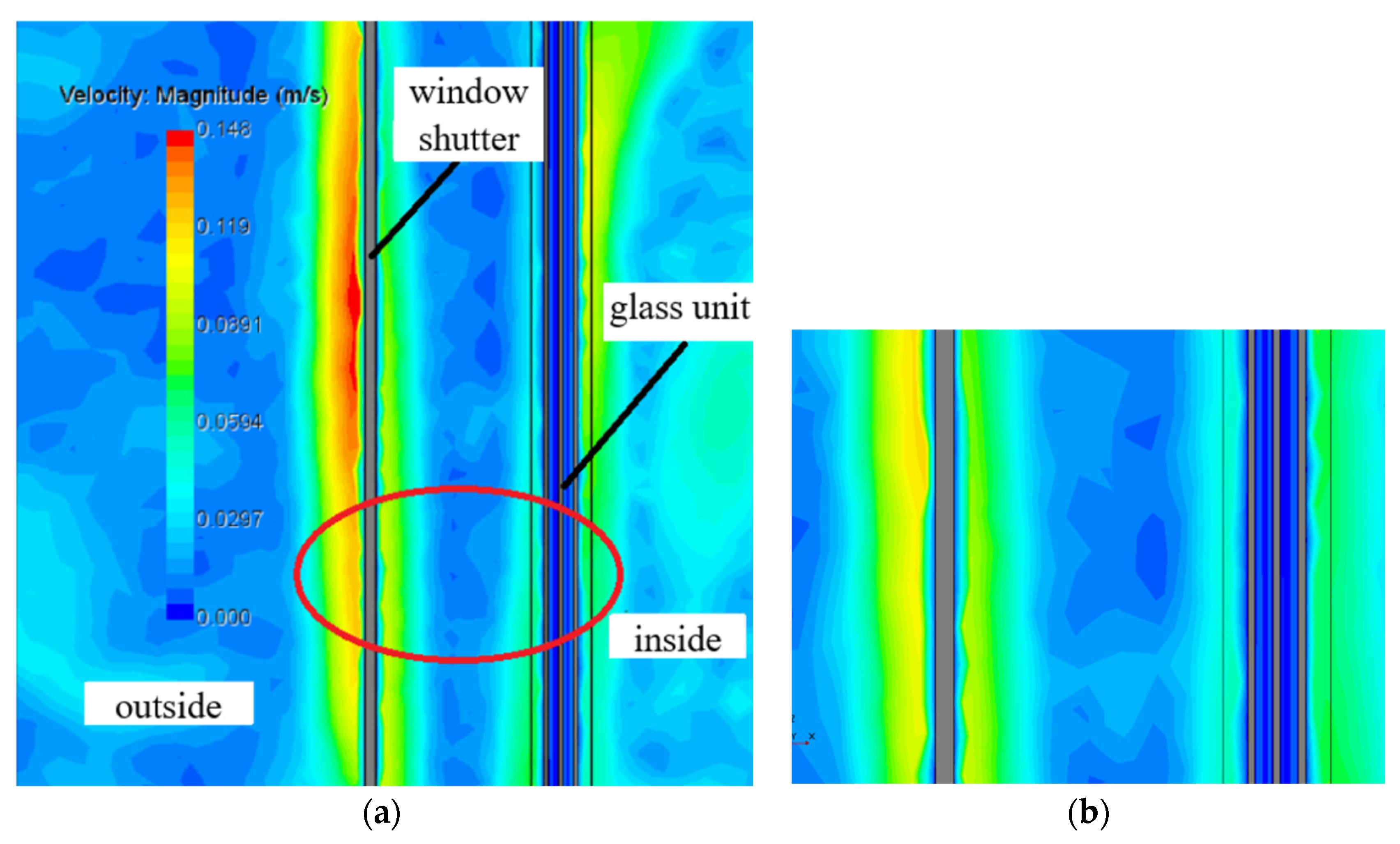
Figure 9.
Photographic view of the window assembly: (a) Frontal view of the hinged shutter E; (b) close-up of heat flux sensors (dark – thermoelectric, ITTF NAS of Ukraine, Ukraine; white – semiconductor (Peltier, denoted as “pel” in Figure 10), China) and a temperature sensor CRT (copper resistance thermometer) affixed with thermal paste.
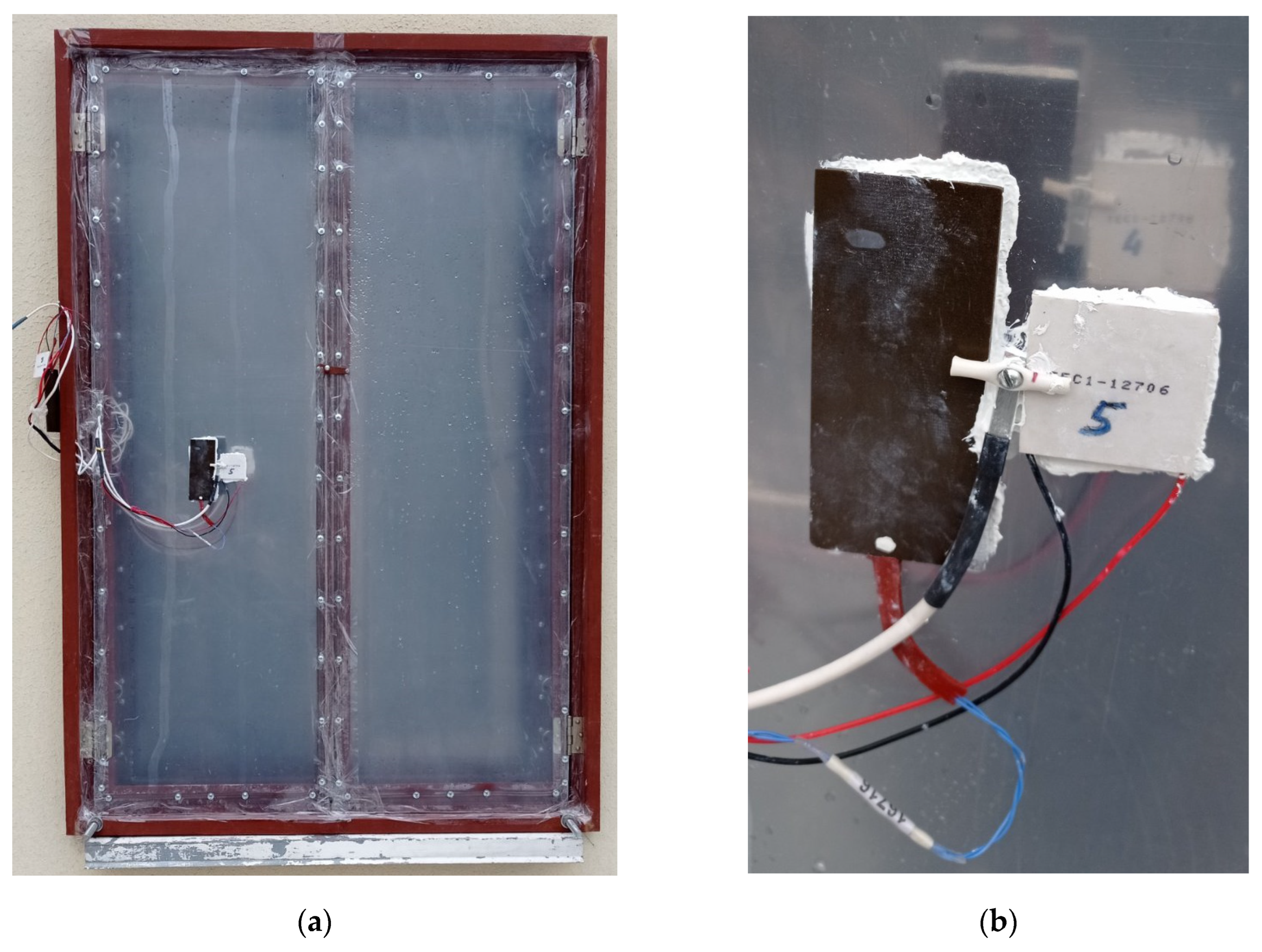
Figure 10.
Experimental data of nighttime temperatures and heat fluxes at key locations within the window block with shutters, for different installation configurations: (a) variant 1; (b), (c) variant 6.
Figure 10.
Experimental data of nighttime temperatures and heat fluxes at key locations within the window block with shutters, for different installation configurations: (a) variant 1; (b), (c) variant 6.
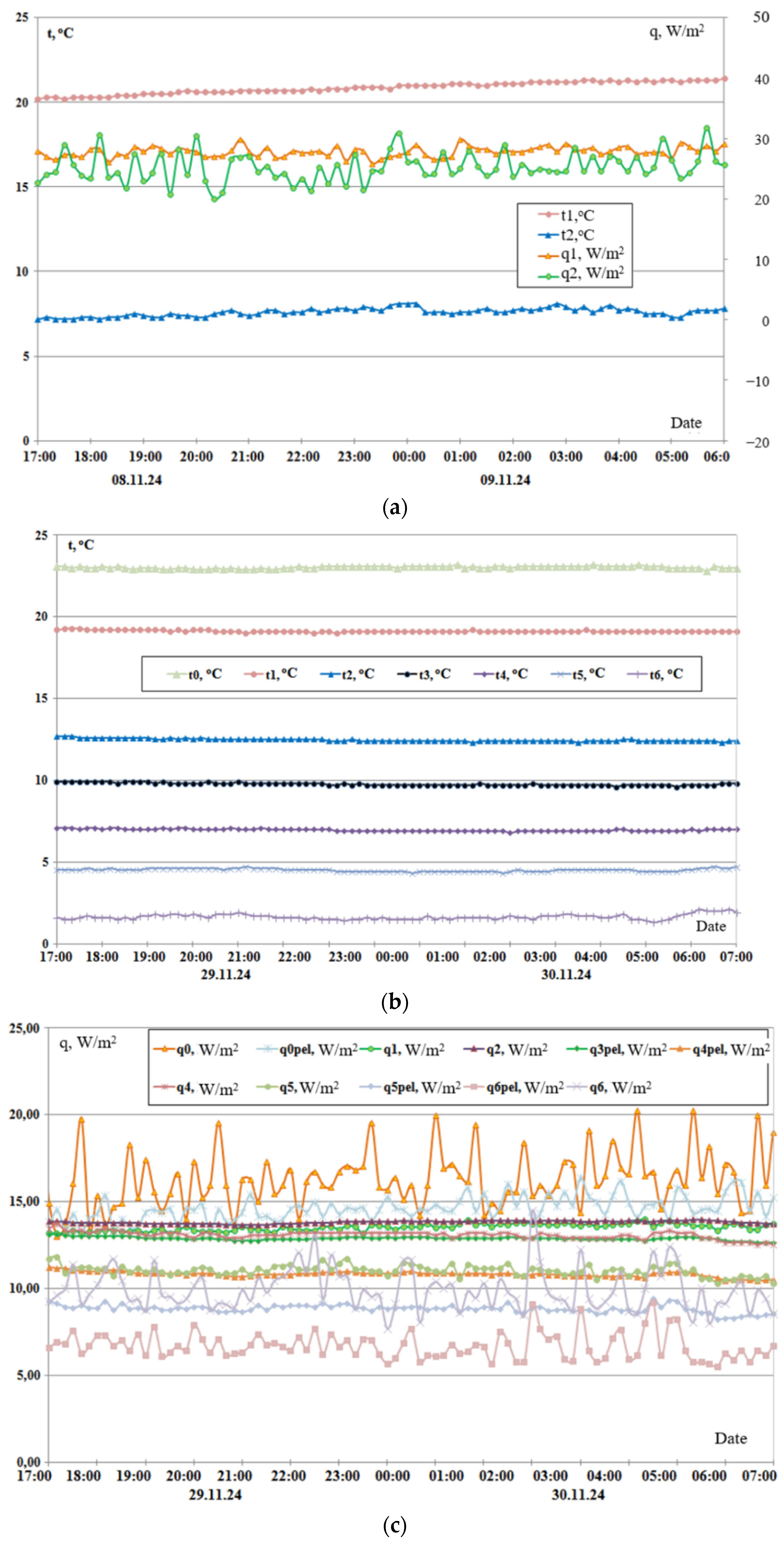

Table 2.
Experimental Thermal Resistance Parameters for the 4M1i-10-4M1-10-4M1 Glazing Unit with Varied Shutter Arrangement.
Table 2.
Experimental Thermal Resistance Parameters for the 4M1i-10-4M1-10-4M1 Glazing Unit with Varied Shutter Arrangement.
| Serial number | Configuration description | Thermal resistance (m²K/W) | Percentage increase in thermal resistance relative to standard window | Increment in thermal resistance relative to preceding configuration (m²K/W) |
|---|---|---|---|---|
| 1 | standard 4M1i-10-4M1-10-4M1 window (DSTU V B2.7-107:2008) | 0.64 | - | - |
| 2 | window only (experimental data: 08-10.11.2024) | 0.63 / 0.64 | - | - |
| 3 | window with one shutter (experimental data: 15-16.11.2024) | 0.80 | 25 | 0.16 |
| 4 | window with two shutters (experimental data: 20-22.11.2024) | 0.99 / 0.97 | 53 | 0.18 |
| 5 | window with three shutters (experimental data: 22-25.11.2024) | 1.09 / 1.11 / 1.13 | 73 | 0.13 |
| 6 | window with four shutters (experimental data: 25-27.11.2024) | 1.27 / 1.25 | 97 | 0.15 |
| 7 | shutter + window with four shutters (experimental data: 25-02.12.2024) |
1.75 / 1.74 / 1.74 / 1.76 | 173 | 0.49 |
Table 1.
Thermal resistance values for window assembly configurations.
| Thermal resistance, (m²K/W) | Var1 | Var2 | Var3 |
|---|---|---|---|
| double-glazed unit (CFD Model) | 0.33 | 0.34 | 0.32 |
| double-glazed unit with shutters (CFD Model) | 0.56 | - | 0.64 |
| double-glazed unit with shutters and i-coating (CFD Model) | 0.62 | - | 0.78 |
| double-glazed unit with i-coating (CFD Model) | 0.43 | 0.48 | 0.43 |
Disclaimer/Publisher’s Note: The statements, opinions and data contained in all publications are solely those of the individual author(s) and contributor(s) and not of MDPI and/or the editor(s). MDPI and/or the editor(s) disclaim responsibility for any injury to people or property resulting from any ideas, methods, instructions or products referred to in the content. |
© 2025 by the authors. Licensee MDPI, Basel, Switzerland. This article is an open access article distributed under the terms and conditions of the Creative Commons Attribution (CC BY) license (http://creativecommons.org/licenses/by/4.0/).
Copyright: This open access article is published under a Creative Commons CC BY 4.0 license, which permit the free download, distribution, and reuse, provided that the author and preprint are cited in any reuse.


