Submitted:
21 September 2024
Posted:
23 September 2024
You are already at the latest version
Abstract
In this paper, we present an improved 100CMM regenerative thermal oxidizer (RTO) designed for low-emission combustion, capable of processing over 95% of volatile organic compound (VOC) gas emissions at generating sites. The existing RTO system features a cylindrical drum structure that cyclically introduces and discharges VOC gas into a rotating disk, achieving excellent energy efficiency with a heat recovery rate exceeding 95%. However, the driving force exerted on the rotating disk in the RTO combustion chamber causes increased wear around the rotating shaft, leading to untreated gas being released through the outlet due to the channeling phenomenon. Additionally, prolonged use can result in operational issues such as rotation stoppages or explosions caused by pollutant discharge, dust accumulation, and thermal expansion at high temperatures of up to 800°C. To address these challenges, we designed an enhanced rotating plate drive unit while ensuring the stable operation of the RTO combustion chamber. Considering that the combustion chamber can reach temperatures of up to 920°C when processing high-concentration VOC gas, the gas burner has been designed with a diameter of 125 mm, and the outlet dimensions are set to 650 mm x 650 mm to effectively discharge high-temperature waste heat. The heat storage material in the combustion chamber is configured with a ceramic block thickness, and the outer diameter and height of the combustion chamber are set at 250 mm, 2,530 mm, and 1,875 mm, respectively, to optimize the gas residence time and the insulation material thickness. Empirical experiments were conducted to analyze changes in VOC removal efficiency, nitrogen oxide emission concentration, and total hydrocarbon (THC) concentration, ultimately evaluating the economic performance of the 100CMM RTO.
Keywords:
100 CMM RTO
; VOCs reduction
; carbon-zero
; combustion & emission
; THC
1. Introduction
Globally, efforts are being made to reduce greenhouse gases and achieve zero carbon emissions in response to global warming. The goal is to keep the increase in global average temperature due to climate change within 2°C above pre-industrial levels, with a long-term target of limiting it to 1.5°C [1]. Industrial emissions of volatile organic compounds (VOCs) must be urgently addressed due to their toxicity and carcinogenicity to humans. Developing efficient and eco-friendly reforming technologies for VOCs is essential but remains a significant challenge [2].
VOCs emitted from chemical plants, metal painting facilities, and petroleum plants contribute to air pollution and pose serious health risks, including toxicity and carcinogenicity. Thus, the development of eco-friendly technologies for their treatment is a critical task [3,4]. Meanwhile, technologies for carbon capture, utilization, and storage (CCUS) have been proposed to address CO₂ emissions from petrochemical and coal-fired power plants [5].
Typically, maintenance activities such as pipe replacement, facility cleaning, residual gas removal, and process improvement are conducted every 4 to 5 years. However, most facilities are outdated, operate with low efficiency, and emit substantial amounts of pollutants, thereby severely impacting the environment. To develop innovative solutions and improve fuel combustion efficiency, previous literature [6] suggested methods to enhance fuel conversion efficiency by heating the substrate during the combustion process and recovering heat from the combustion gas through cooling and steam condensation.
To analyze the reduction in nitrogen oxide (NOₓ) emissions, the design and system were studied in terms of the effects of temperature, oxygen concentration, and secondary combustion air volume in a single burner combustion system [8]. Park, H. M., Yoon, D. H., Jung, H. M., and Jon, D. H. [8] published a study on the development of porous plate scrubbers and simulations of isopropyl alcohol (IPA) treatment efficiency for improved dust collection and deodorization.
One of the environmentally friendly methods for emission reduction involves low-emission waste energy utilization through the combustion of liquid fuel mixed with superheated steam and carbon dioxide in the combustion zone [9]. This approach benefits from the reduction and recycling of CO₂ by utilizing it alongside or in place of steam.
Until now, VOC removal and reduction technologies have included anti-diffusion methods, physical methods, chemical methods, and biological methods [10]. Among chemical methods, combustion has evolved into various approaches, such as direct combustion (thermal oxidation), catalytic oxidation, and regenerative thermal oxidation, which oxidize and decompose VOCs at high temperatures. Despite these advancements, energy costs remain high due to low heat recovery rates. To address this, technologies capable of effectively treating more than 95% of VOCs have been developed, such as heat storage combustion systems and heat storage catalytic combustion systems [11].
Jeon, D. H., and Jung, S. W. [12] studied pretreatment methods for irregular process emissions to enable high-efficiency combustion treatment of VOCs. Park, H-M., Yoon, D-H., and Jeon, D-H. [13] subsequently proposed a method to increase fuel conversion efficiency by heating the substrate during the combustion process and recovering heat from combustion gases through cooling and vapor condensation. Meanwhile, the evolution of heat storage combustion oxidizing agents for VOC treatment has progressed from the first-generation damper method to the third-generation rotary valve method.
To reduce air pollution at VOC production sites, 100CMM regenerative thermal oxidizer (RTO) devices were designed. Heat transfer system specifications and emission concentration measurement techniques were proposed through studies of phase transformations for high-temperature waste heat recovery [14,15,16]. Figure 1 shows the evolution of the heat storage combustion oxidation device.
In this paper, we implement a 100CMM heat storage oxidation device (RTO) for low-emission combustion that can process more than 95% of volatile organic compounds (VOCs) gas generating sites. It compensates for untreated gas emissions due to abrasion and channeling due to the driving force of the disk rotating plate in the combustion chamber, which is pointed out as a disadvantage of the existing RTO.
In addition, when used for a long time, there is a problem that the rotation stops or explodes due to the emission of pollutants due to dust and thermal expansion due to 800°C high temperature. To improve this, we design an improved rotating plate driving unit while maintaining normal operation of the RTO combustion chamber. Considering that the combustion chamber rises to 920°C when high concentration VOC gas is treated, the gas burner is designed to have a diameter of 125 mm, and the outlet is designed to have a size of 650 mm x 650 mm to discharge high-temperature waste heat. At this time, the combustion chamber heat storage material is designed to have a ceramic block thickness, an outer diameter and a height of the combustion chamber at 250 mm, an Ф of 2,530 mm, and 1,875 mm, respectively, in consideration of the treatment gas residence time and the thickness of the insulation material.
2. Implementation of Improved 100 CMM RTO
2.1100. CMM RTO Design
In the existing heat storage-type combustion oxidizer, a rotary distributor in the form of a cylindrical drum with an inlet and an outlet is predominantly used. However, prolonged use of this drum-type rotary distributor can result in operational issues such as rotation stoppage due to high temperatures, thermal expansion, and dust accumulation [4]. Additionally, to minimize friction within the air distribution unit, the air-blocking components in contact with the rotating part are arranged with a 2-3 mm gap. This gap allows VOC gas to enter, mix with the treated exhaust gas, and be released through the final outlet, thereby reducing VOC treatment efficiency. To address this issue, it is crucial to control the gas flow between the rotating and air-blocking parts and to develop a design with superior durability [13,14]. Table 1 presents the specifications of the 100 CMM-class heat storage-type combustion oxidizer.
Table 2 presents the energy balance calculations for the 100CMM-class heat storage-type combustion device material based on the processing gas flow rate and VOC concentration, as outlined in the design criteria in Table 1. The VOC calorific value treatment standard is expressed in terms of the toluene calorific value equivalent.
Although the specified temperature of the combustion chamber varies slightly from country to country, it generally operates within the range of 800 to 950 degrees Celsius, achieving a VOC removal efficiency of 95% or higher using a burner. The thermal efficiency (η) of the combustion chamber is calculated using Equation (1). When the combustion chamber temperature is 800 degrees Celsius, a removal efficiency of 95% or more can be obtained [13].
Here, represents the RTO combustion chamber temperature, represents the stack emission temperature, and represents the inlet temperature of the RTO.
Based on the design data from Table 1 and Table 2, Figure 2 illustrates the 3D model of the RTO, which comprises contaminated gas inlets, purge gas inlets, rotators, rails, rail covers, combustion chambers, heat storage material support structures, and treated gas outlets.
The upper and lower surfaces of the chamber are supported by a rail cover set, which significantly reduces the likelihood of the intermediate plate’s rotation being obstructed by factors such as foreign substances. The system is designed to maintain stable gas inflow and outflow distribution by rotating the intermediate plate. When components related to the upper and lower rails wear out due to prolonged use, the gap between the upper and lower plates can be adjusted using a gap adjustment mechanism consisting of a turnbuckle. This allows for easy maintenance and performance retention even when parts are worn. The intermediate plate and its surrounding configuration are designed as a modular package, facilitating the maintenance and disassembly of the lower plate from the upper plate, which is attached to the lower part of the chamber. Holding mechanisms are installed on both the upper and lower plates to prevent deflection by maintaining a gap between the intermediate plates with repulsive force, thereby extending the lifespan by reducing wear on rail-related components.
Based on Table 1 and Table 2, the specifications of the burner are selected with consideration of energy efficiency. The combustion efficiency within the chamber can be influenced not only by the efficiency of the burner but also by the inconsistent supply of VOC gas from the plant. The role of maintaining the chamber temperature at 800 degrees Celsius and removing more than 95% of harmful gases is supported by supplying LNG gas when the VOC gas supply is insufficient. Although the use of LNG increases operational costs, it is necessary to achieve the goal of harmful gas removal. Future research should focus on maintaining a consistent temperature within the chamber [15].
The RTO combustion chamber utilizes LNG gas for combustion, and the amount of combustion energy required is determined based on the LNG price per cubic meter [13]. If the LNG price is calculated at $700, and the solvent calorific value of 221,540 Kcal/hr from Table 2 is used, the combustion energy amounts to 117,575 Kcal/hr, with a hot bypass leak of 11,758 Kcal/hr. Additionally, the energy loss from the purge and COMB fan is 11,750 Kcal/hr. At high temperatures, the heating energy required is calculated as:
Heating energy = Q×heat×0.15×(complexion room temperature−incoming temperature)× (1−heat recovery rate)×60 min/hr = 17,208 Kcal/hr
Therefore, the total fuel consumption for the RTO is 80,450 Kcal/hr. Table 3 presents the heat recovery energy, the quantity of heat storage material, and the pressure loss in the combustion chamber, based on the data from Table 1 and Table 2. In this setup, the heat loss volume is 40 m³, and the total volume of the heat storage material is 2 m³.
2.2. Improvement of Distributor and Design of Heat Storage Materials
In Figure 2, for the normal operation of the RTO combustion chamber, the gas burner was designed with a diameter of 125 mm, and the outlet was sized at 650 mm x 650 mm to efficiently discharge high-temperature waste heat. The combustion chamber heat storage material is specified as a ceramic block with a thickness of 250 mm. Considering the residence time of the treatment gas and the thickness of the insulation, the combustion chamber was designed with an outer diameter of 2,530 mm and a height of 1,875 mm. Long-term use of the heat storage material may result in damage due to thermal shock and fatigue, necessitating periodic inspection and replacement. Figure 3 illustrates the rotary periphery that supports the disk rotating plate’s movement and the disk that directs the flow of VOC gas.
To address the shortcomings identified in Figure 3, the rotating plate drive is redesigned towards the RTO side, as shown in Figure 4, and its performance is analyzed through gas flow analysis.
Figure 5 illustrates the arrangement design of the heat storage material within the combustion chamber. Although a cylindrical structure is used for the heat storage material filling section, the ceramic filling arrangement has been modified from the existing design to minimize unused areas and reduce the device size. This new arrangement design reduces the device diameter from Φ 2,610 mm to Φ 2,480 mm and improves the number of ceramic fillings by reducing a total of 60 units (5 per zone x 12 zones = 60) compared to the previous method.
Figure 6 is a design diagram of the VOCs gas input unit, purge input unit and output unit in the rotary part located at the bottom of the combustion chamber of Figure 3 and Figure 4, and Table 5 shows the analysis conditions.
In the air pollution process test method, the concentration of the facility inlet gas and exhaust gas is simultaneously measured using the total hydrocarbon (THC) analysis method to calculate the VOC reduction rate, as shown in Equation (3) below.
3. Experimental Results
3.1. The Simulation of RTO and Flowability Analysis
In Figure 5, 3.3 m³/min is considered the air volume that can be processed per ceramic unit, and the number of disks is determined based on the ceramic arrangement table. Although the designed RTO capacity is 100 CMM, the actual experiment simulates an air volume of 120 CMM. The RTO diameter used for this experiment is 2,180 mm, with 240 ceramic units installed. The interrelationship between factors such as treatment air volume, ceramic arrangement length, and RTO diameter is taken into account, and a gas flow analysis within the RTO chamber is conducted through simulations based on criteria step.
Figure 7 shows the temperature distribution within the combustion chamber and the combustion behavior, including the generation of unburned VOC gas, as influenced by the burner’s heat. A jet flow is formed according to the burner’s flame pattern, resulting in a curved shape that indicates temperature non-uniformity. Additionally, the green area at the center of the jet flow represents the section where VOC gas remains unburned.
Figure 8 shows the flowability of gas flows attracting and output from the rotary part according to the simulation of the operation and control characteristics of the combustion chamber based on Figure 6 and Figure 7.
It displays the range from the lowest values, represented in blue, to the highest values, represented in red, according to the units of pressure [Pa], speed [m/s], and concentration [g-mol/kg], respectively. Table 6 presents the values measured after the RTO reaches a stable operating state, as illustrated in Figure 7 and Figure 8.
3.2. VOCs Gas Emission Test Based on Film Coating Device
For field experiments, the concentration of VOC gas emissions generated from the coating film production system is tested. The validity of the experiment is verified through the nationally accredited Korea Testing Laboratory (KTL). Figure 9 shows the gas concentration values emitted from the film drying and printing sections of the coating film production system.
The VOC concentration in the drying section ranged from a maximum of 3,979 ppm to a minimum of 593 ppm, with an average total hydrocarbon (THC) concentration of 2,567 ppm. In the printing section, the concentration ranged from a maximum of 2,170 ppm to a minimum of 686 ppm, with an average THC concentration of 1,260 ppm. Figure 10 shows the construction of a 100 CMM RTO device connected to the system shown in Figure 9. The combustion chamber body with the ceramic array and the burner are connected, and the rotary with fans is installed to introduce exhaust gas from the coating machine. Finally, a monitor with programmable logic controller (PLC) device are incorporated into the setup.
Based on Table 6, the VOC gas entering the RTO device from the plant passes through a layer of ceramic heat storage material, is preheated in the rotary input and chamber, is combusted with a burner, and is then discharged through the stack in that order. During this process, the heat generated in the chamber oxidizes and decomposes the gas at temperatures ranging from 700 to 850°C. The exhaust gas then passes through the heat storage material on the outlet side, storing high-temperature waste heat in the ceramic. Heat storage and dissipation occur alternately at regular intervals according to the operating cycle. At this stage, the heat recovery efficiency exceeds 95%, and the treatment efficiency achieves over 97.898% oxidation and decomposition, resulting in the release of harmless and odorless clean gas at 60°C. Table 7 presents the test results based on the data in Table 6, showing the VOC removal efficiency calculated from THC and the actual nitrogen oxide measurements using Equation (3).
After the combustion chamber operating temperature reaches 800℃, it decreases to 750℃ at 50Hz due to the site exhaust gas blower. At this point, when the burner is activated to restore the temperature to its normal level, the combustion chamber temperature rises and fluctuates between 799℃ and 804℃, with a deviation of approximately 5℃. This fluctuation is caused by the irregular VOC emissions from the plant, which require additional energy to activate the burner in order to maintain the RTO chamber temperature. This factor is crucial in assessing the interoperability and cost-efficiency between the plant and the RTO device. In the RTO simulation, the average concentration of the inlet gas, based on the operating temperature of the combustion chamber, was 6,224 ppm (THC), while the RTO combustion chamber temperature was 815°C. The THC concentration exhaust and combustion chamber temperature fluctuated between a minimum of 808°C and a maximum of 825°C, as shown in Figure 11.
4. Conclusions
In this paper, we present an improved 100CMM heat storage oxidation device (RTO) for low-emission combustion, capable of processing more than 95% of volatile organic compound (VOC) gases at generating sites. The existing RTO system utilizes a cylindrical drum structure that repeatedly introduces and discharges VOC gas to a rotating disk, achieving excellent energy efficiency with a heat recovery rate of over 95%. However, the driving force exerted on the rotating disk in the RTO combustion chamber increases wear around the rotating shaft, leading to the discharge of untreated gas through the outlet due to the channeling phenomenon. Additionally, prolonged use at high temperatures of 800°C can cause operational issues such as rotation stoppages or even explosions due to the accumulation of pollutants, dust, and thermal expansion.
To address these challenges, we designed an improved rotating plate drive unit while ensuring the normal operation of the RTO combustion chamber. Considering that the combustion chamber temperature can rise to 920°C when treating high-concentration VOC gas, the gas burner was designed with a diameter of 125 mm, and the outlet was designed to measure 650 mm x 650 mm to effectively discharge high-temperature waste heat. The heat storage material in the combustion chamber was configured with a ceramic block thickness of 250 mm, and the chamber’s outer diameter and height were set to 2,530 mm and 1,875 mm, respectively, taking into account the gas residence time and the thickness of the insulation material.
Empirical experiments conducted with the RTO system integrated into a film coating plant demonstrated changes in VOC removal efficiency, nitrogen oxide emission concentration, and THC (total hydrocarbon) concentration, achieving a removal efficiency of more than 97.90%.
This study addresses the issues with the 100 CMM RTO design through simulation and optimization based on specified parameters and data. By presenting a method for evaluating economic feasibility through performance assessment of the 100 CMM system, we aim to contribute to future research focused on energy reduction.
Author Contributions
Conceptualization and formal analysis, Park, H.M.; formal analysis & design, Jung, H.M.; methodology and synthesis, Lee, D.H.; simulation & validation, Lim, T.Y.; system management & validation, Park, H.N.; writing—original draft, review and editing, Yoon, D.H.
All authors have read and agreed to the published version of the manuscript.
Funding
This research received external funding.
Institutional Review Board Statement
Not applicable.
Informed Consent Statement
Not applicable.
Acknowledgments
This work was supported by Ministry of Trade, Industry and Energy Republic of Korea grant funded by the Korea Evaluation institute of Industrial Technology (Project No. 20023721).
Conflicts of Interest
The authors declare no conflict of interest. The funders had no role in the research design, data collection, analysis, or interpretation, manuscript preparation, or the decision to publish the results.
References
- Moon, S.H. Non-CO2 Greenhouse Gas Reduction Technology Status, Seminar Material of Korea Institute of Future Technology, 18 June 2021.
- Yoon, J. H. Transboundary Air Pollution and Global Governance: Singapore’s Network Strategy to Tackle the Indonesian Haze, Korean Society for Regional Studies, Republic of Korea, 2016; Vol.34, No.1, pp.51-79. https://www.dbpia.co.kr/Journal/articleDetail?nodeId=NODE08788063.
- Bian, C.; Huang, J.; Zhong, B.; Zheng, Z.; Dang, D.; Okafor, O.C.; Liu, Y.; Wang, T. Autothermal Reforming of Volatile Organic Compounds to Hydrogen-Rich Gas, Molecules, 2023; Vol.28, 752. [CrossRef]
- Lee, H. J.; Chao, M. H.; Ko, D.R. Causative Substance and Time of Mortality Presented to Emergency Department Following Acute Poisoning: 2014-2018 National Emergency Department Information System, Journal of The Korean Society of Clinical Toxicology, 2021; Vol.19 Issue 2, pp.65-71, https://koreascience.kr/article/JAKO20210985834.
- Hasegawa, T. Gas Turbine Combustion and Ammonia Removal Technology of Gasified Fuels, Energies, 2010; Vol. 3, pp.335–449. [CrossRef]
- Hou, S.S.; Chiang, C.Y.; Lin, T.H. Oxy-Fuel Combustion Characteristics of Pulverized Coal under O2/Recirculated Flue Gas Atmospheres, Applied Sciences 2020; Vol.10, pp.13-62. [CrossRef]
- Sung, Y. M.; Kim, S. T.; Jang, B. H.; Oh, C. Y.; Jee, T. Y.; Park, S. I.; Park, K. S.; Chang, S. Y. Nitric Oxide Emission Reduction in Reheating Furnaces through Burner and Furnace Air-Staged Combustions, Energies, 2021; Vol.14, 1599. [CrossRef]
- Park, H. M.; Yoon, D. H.; Jung, H. M.; Jeon, D. H. Development of Porous Plate Scrubbers and Simulation of IPA Treatment Efficiency to Improve Dust Collection and Deodorization, Korea Safety and Culture Research, Republic of Korea, 2021; Vol.13 No.1, pp.339-349. [CrossRef]
- Sadkin, I.; Mukhina, M.; Kopyev, E.; Sharypov, O.; Alekseenko, S. Low-Emission Waste-to-Energy Method of Liquid Fuel Combustion with a Mixture of Superheated Steam and Carbon Dioxide, Energies, 2023; Vol.16, 5745. [CrossRef]
- Choi, B. S.; Yi, J. Simulation and Optimization on the Regenerative Thermal Oxidation of Volatile Organic Compounds, Elsevier, Chemical Engineering Journal, 2000; Vol.76, Issue 2, pp.103-114. [CrossRef]
- Khakimova, L.; Popov, E.; Cheremisin, A. Insights on In Situ Combustion Modeling Based on a Ramped Temperature Oxidation Experiment for Oil Sand Bitumen, Energies, 2023; Vol.16, 6738. [CrossRef]
- Jeon, D.H.; Jeng, S.W. Pre-treatment Method of Irregular Process Emissions for High-Efficiency Combustion Treatment of Volatile Organic Compounds, Autumn Conference of the Korea Gas Association, Republic of Korea, 2021.
- Yoon, D.H.; Han, B. S.; Lim, T.Y.; Yang, E.C. Implementation of 100CMM Thermal Storage Combustion Oxidizer for VOCs Reduction, 2022 International Conference on Control, Automation and Systems, 2022; pp1-25. Available online: https://ieeexplore.ieee.org/xpl/conhome/10003266.
- Park, H. M.; Jung, H. M; Lee, D.H.; Lim, T.Y.; Yoon, D. H. VOCs Oxidation Treatment and Waste Heat Recovery Technology through the Implementation of Heat Storage Type Combustion Oxidation Device, Korean Journal of Safety Culture, 2022; Vol.17, pp.285-298. [CrossRef]
- Park, H.M.; Yoon, D.H.; Jeon, D.H.; Min, H.K. Nitrogen Oxide Reduction Type Regenerative Thermal Oxidation System and Nitrogen Oxide Reduction Method Thereof, United States Patent Application Publication, 2023; No: US 2023/0228205 A1.
- Park, H.M.; Yoon, D.H.; Jeon, D.H.; Min, H.K. Multistage Variable Type Waste Heat Storage and Recovery Apparatus and Method Thereof, United States Patent Application Publication, 2023; No: US 2023/0228500 A1.
- www.ktl.re.kr, Korea Testing Laboratory (KTL), Republic of Korea.
Figure 1.
The evolution of the heat storage combustion oxidation device.
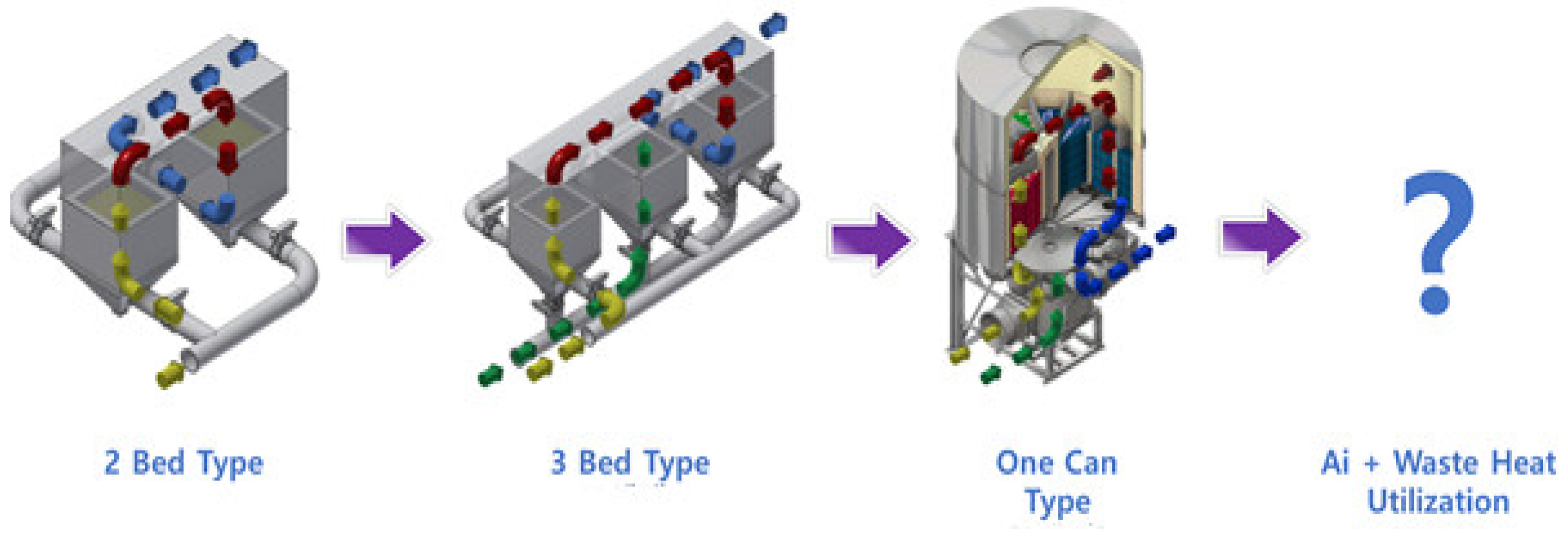
Figure 2.
Configuration of RTO 3D model.
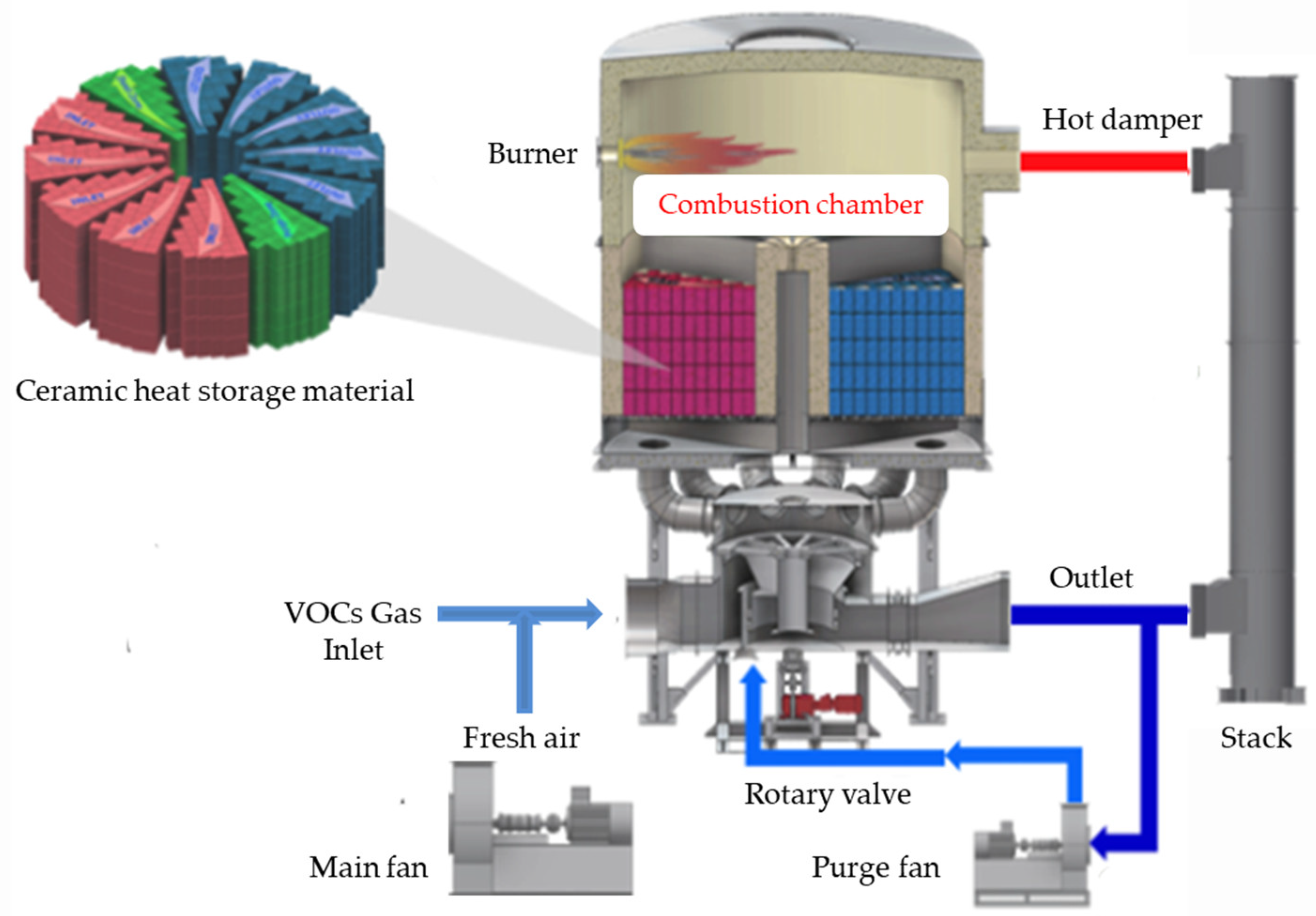
Figure 3.
The rotary periphery and disk rotating plate.
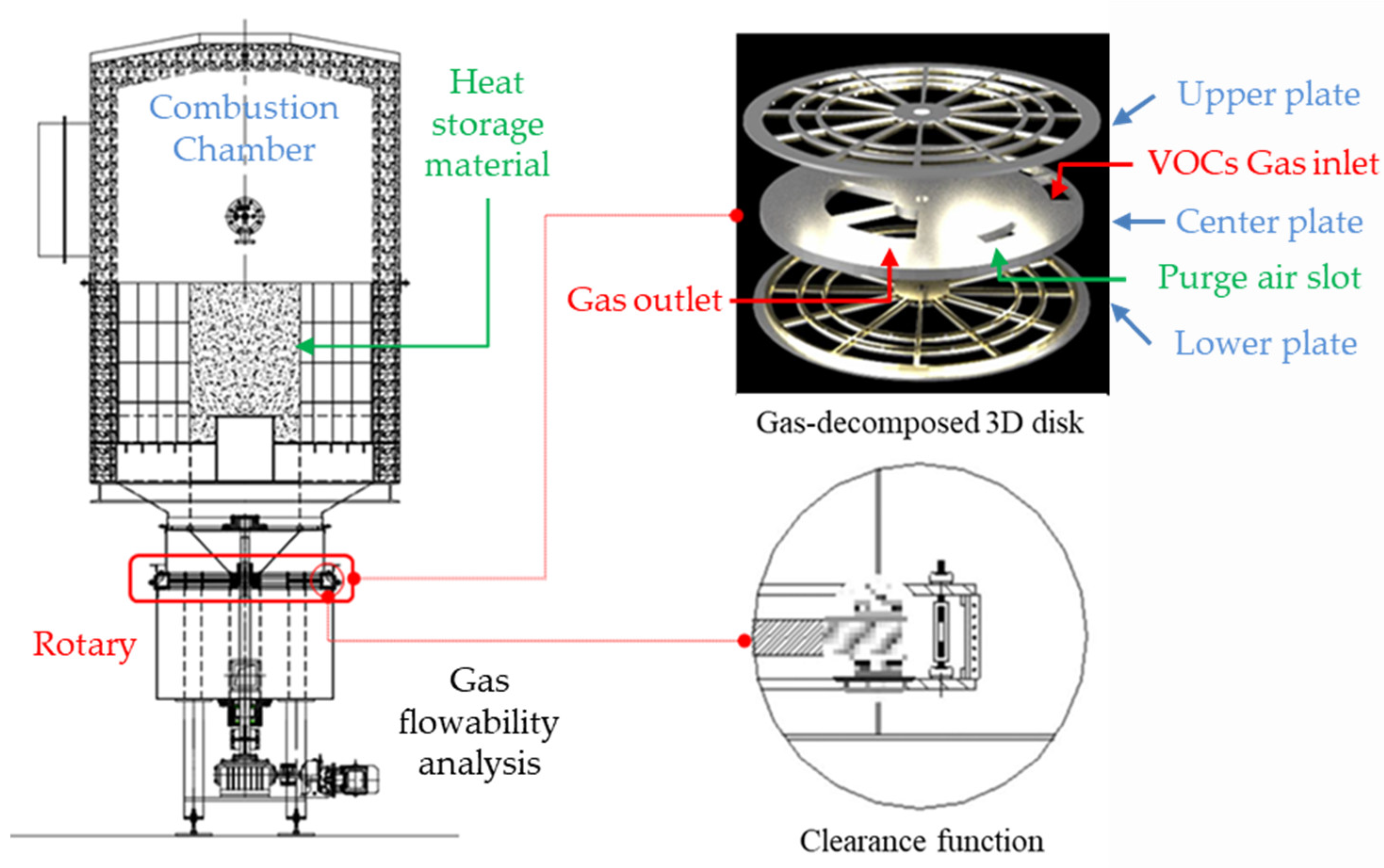
Figure 4.
Improved RTO distributor design and fabrication.
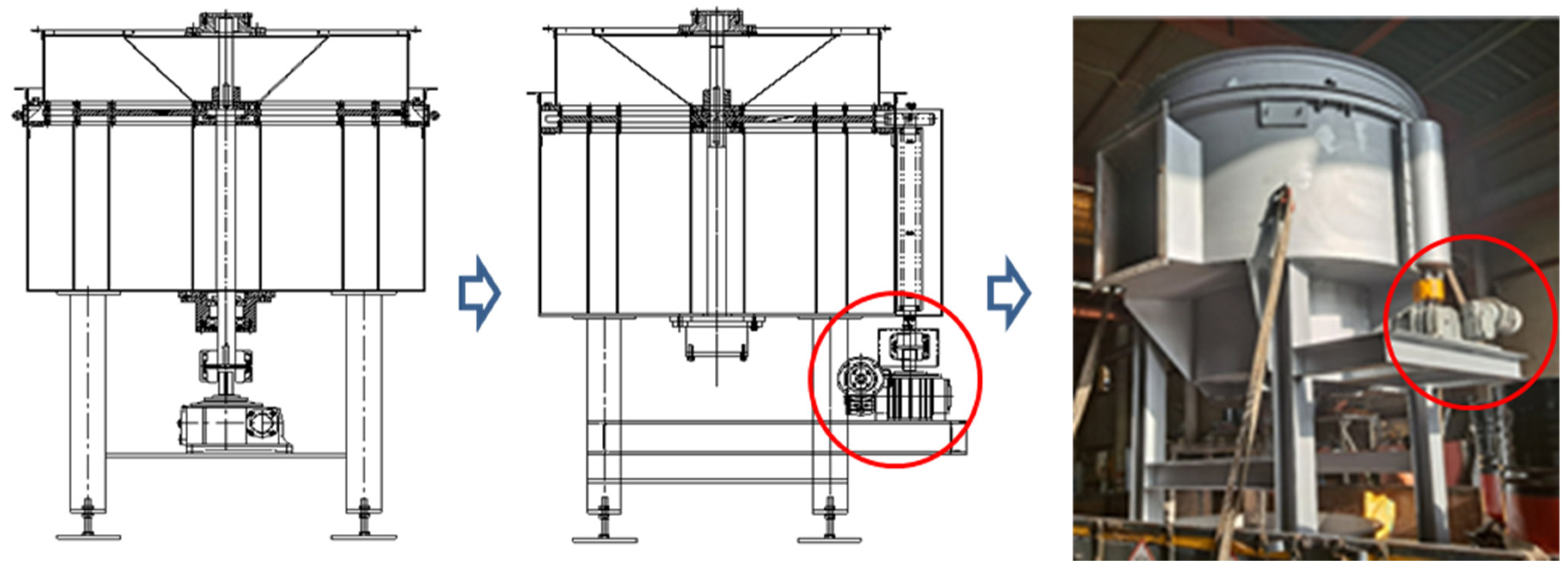
Figure 5.
The heat storage agent arrangement design in chamber.
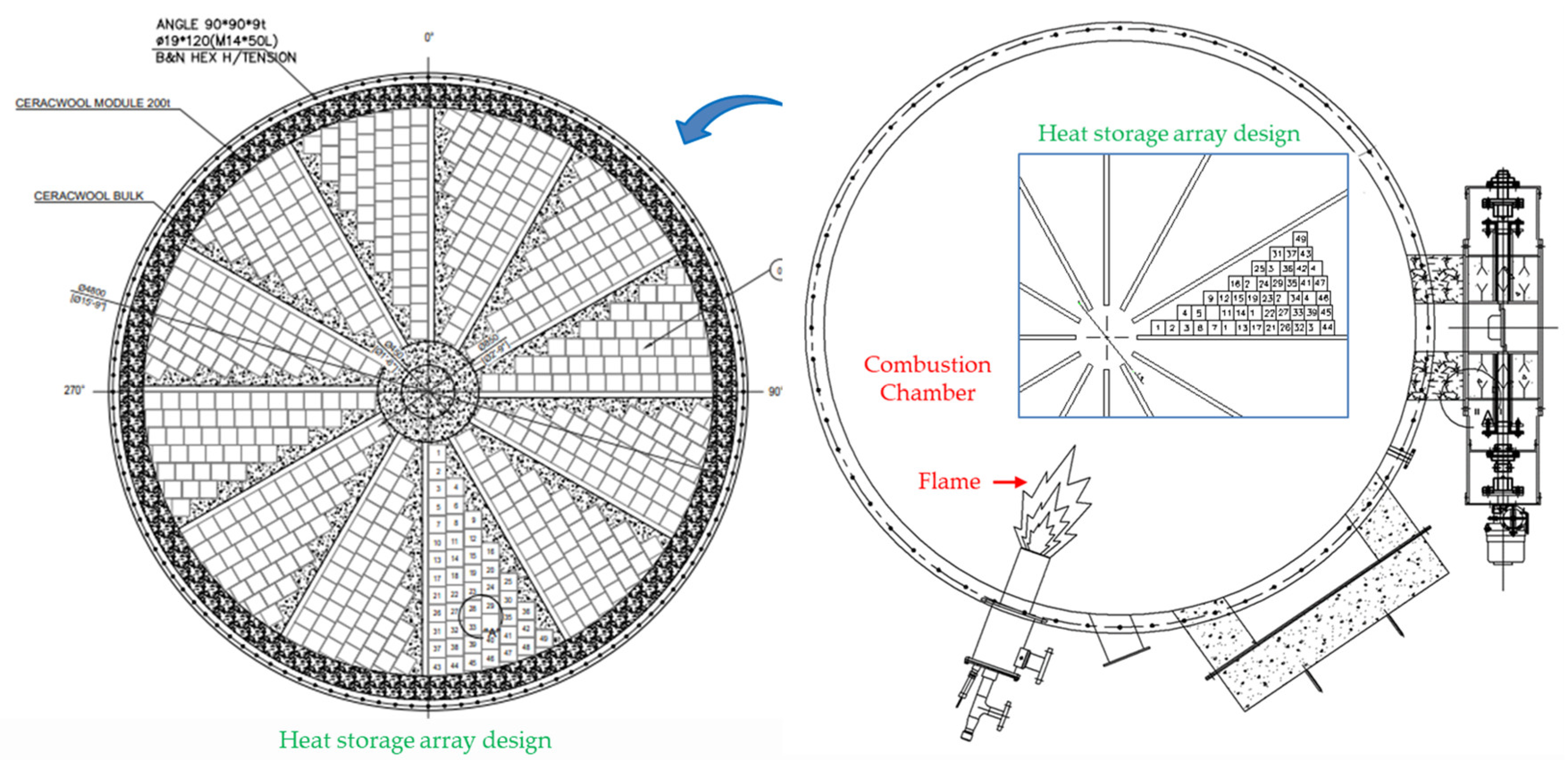
Figure 6.
Design of rotary part.
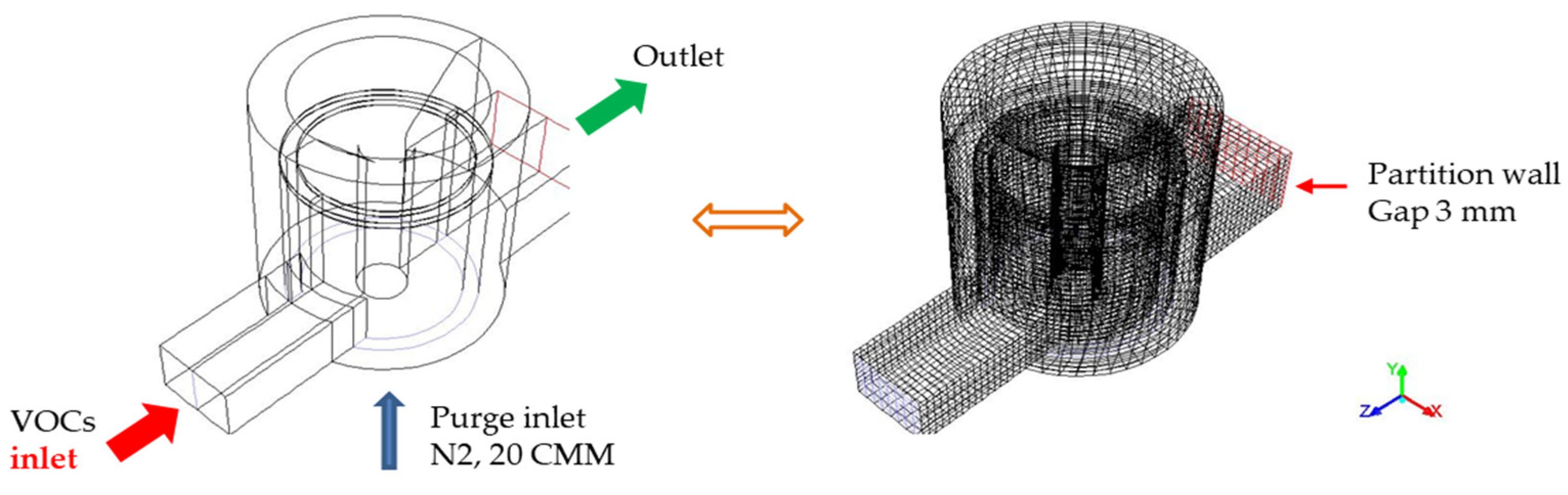
Figure 7.
Jet stream and combustion of VOCs gas.
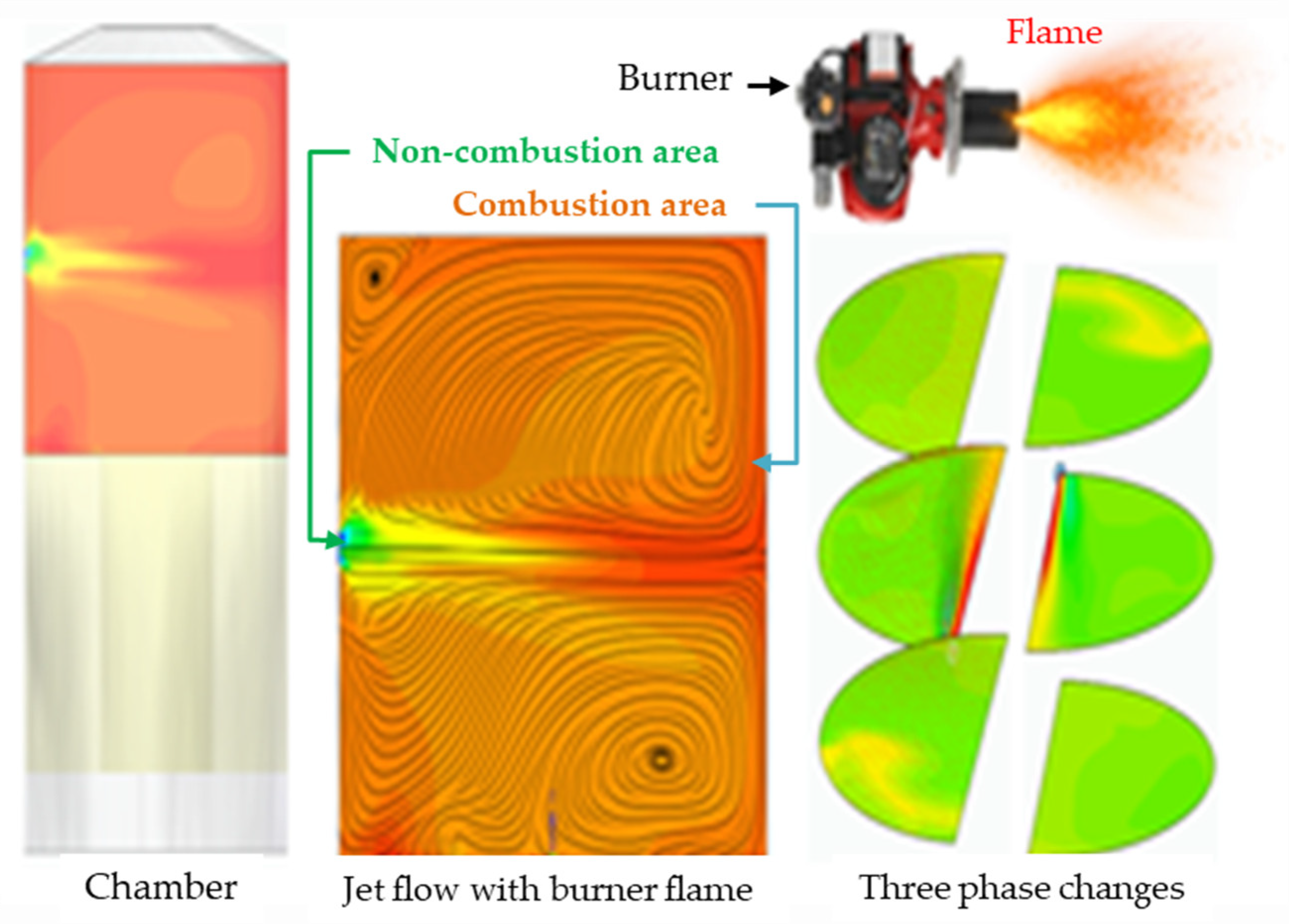
Figure 8.
Flowability analysis of gas flows.
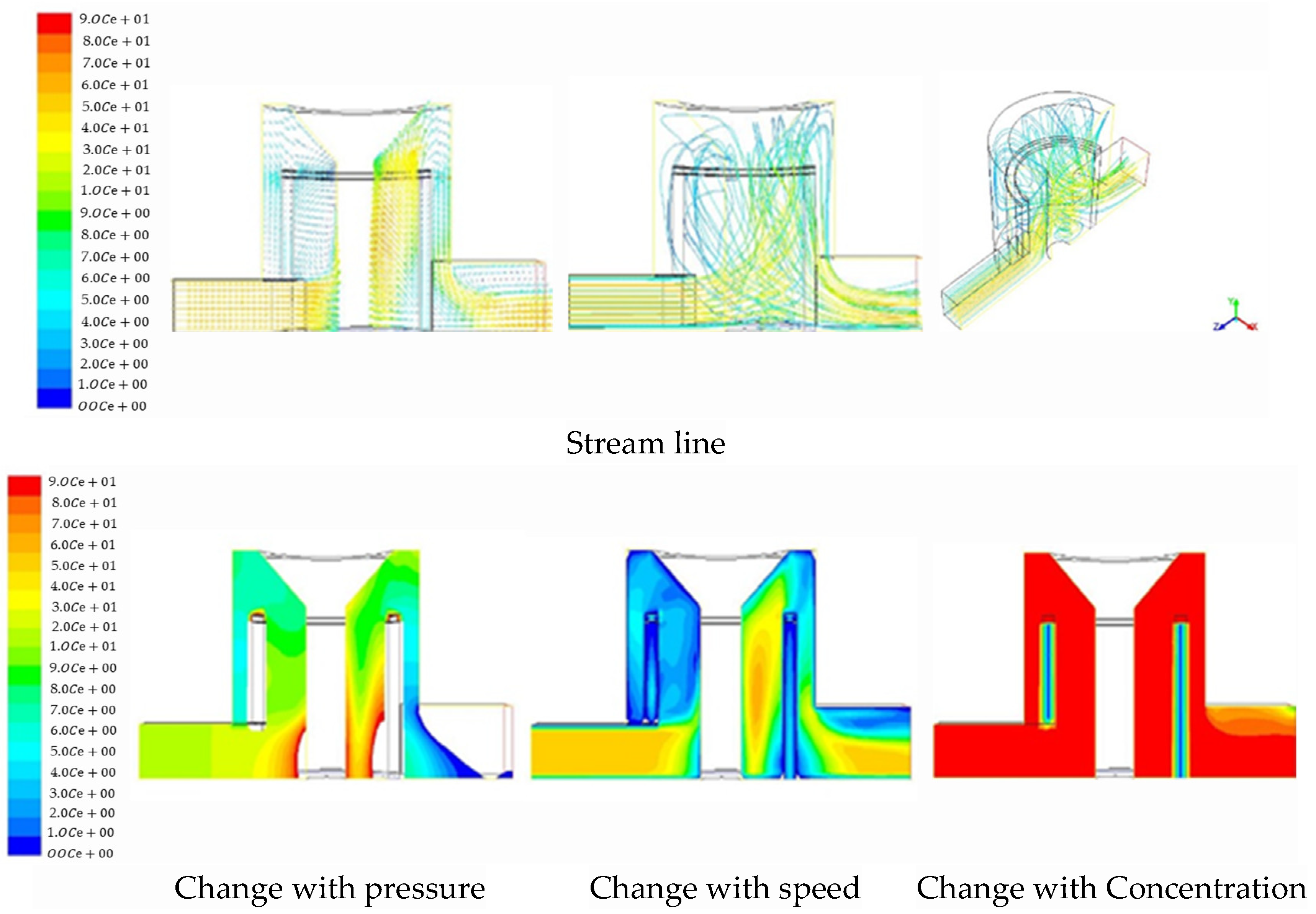
Figure 9.
VOCs concentration discharged from the coating film system.
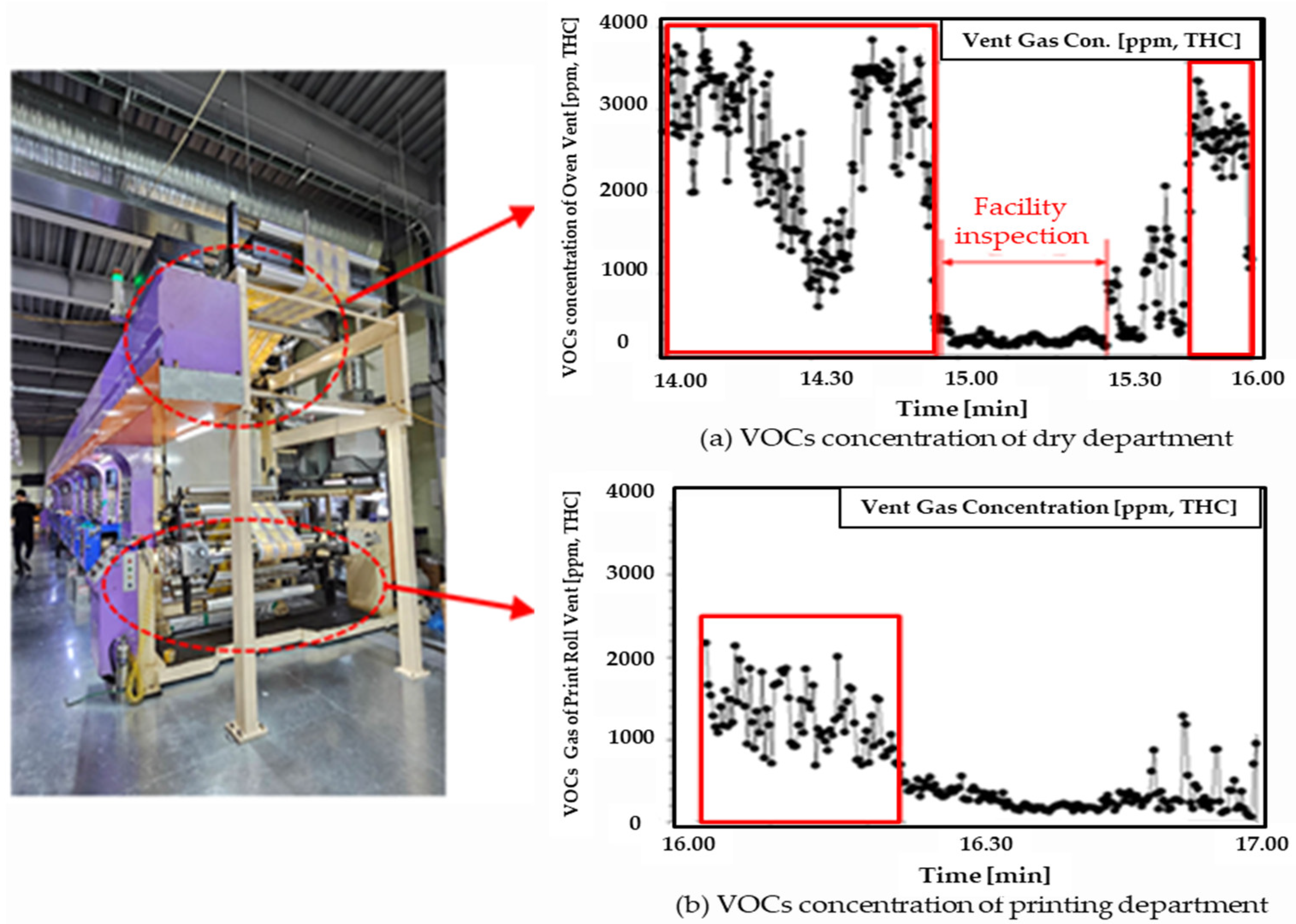
Figure 10.
100 CMM RTO demonstration device.
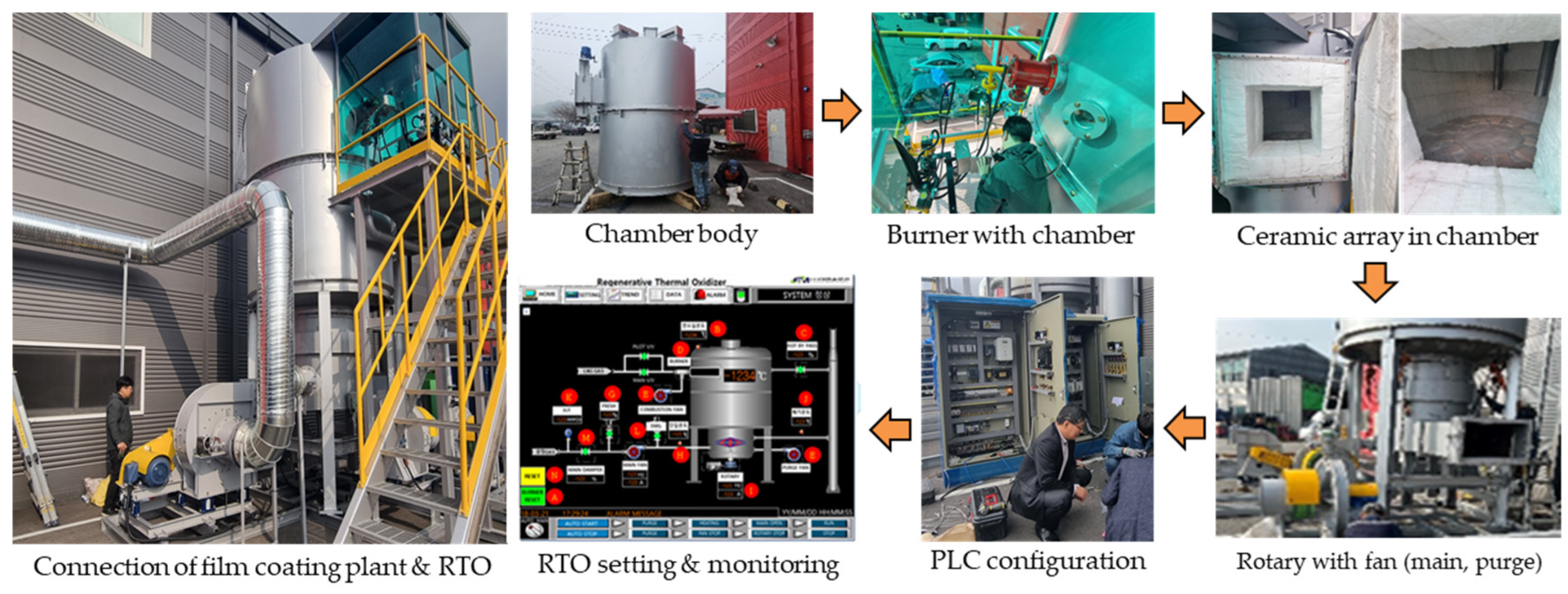
Figure 11.
The THC concentration exhaust and combustion chamber temperature fluctuated.
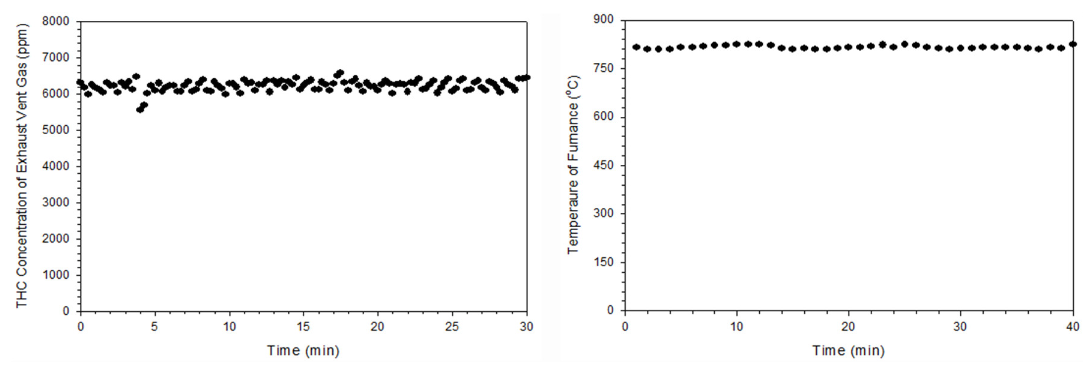

Table 1.
The specifications of a 100 CMM RTO.
| Process | Usage specification | Unit |
|---|---|---|
| Waste GAS volume | 100 | m3/min |
| Exhausted temperature of RTO inlet | 20 | ℃ |
| Substance name to be treated (Based on Toluene calorific value) |
VOCs - 2,000 | ppm |
| FUME (smoke - 4 degrees or higher) | - | |
| Stench (over 4 degrees) | ||
| VOC generation | 43 | kg/hr |
| Utility | LPG, Electric (380V*3Φ*60Hz) | - |
| STACK emission temperature | 60 | ±3℃ less than |
Table 2.
The specification of VOC calorific value.
| VOC | Emission concentration | Emissions | Unit Combustion Heat | The amount of heat burned | Explosion limit |
| ppm | kg/h | kcal/kg | kcal/h | Vol/% | |
| Methacrylic acid | 2,000 | 43 | 5,150 | 221,540 | 0.0 |
Table 3.
Heat storage material design value of combustion chamber.
| Heat storage material items | Configuration material | Design Specifications |
|---|---|---|
| Recovery energy | Heat accumulator passing temperature | 735 ℃ |
| Heat storage material recovery calorific value | 1,911,341 Kcal/hr | |
| Heat storage material | Heat exchange rate | 31,856 Kcal/hr |
| Total area of heat storage material | 2 m3 | |
| Pressure loss | A heat storage material | 100 mmAq |
| Stack | 5 mmAq | |
| Rotary | 3 mmAq | |
| a sudden zoom | 45 mmAq | |
| Etc. | 100 mmAq | |
| Total | 253 mmAq |
Table 4.
Economic production based on monthly maintenance costs.
| Economic items | Monthly maintenance costs |
|---|---|
| Normal heating fuel production | 802,106 kcal/hr ÷ 15,000 kcal/Nm3.LNG x 0.5 hr/day x 3 day/month x 700 $/Nm3.LNG = 56,147 $/month |
| Fuel production per hour | 0 day/month x 30 day/month x 700 /Nm3.LNG Total monthly fuel use cost: 56,147 /month |
| Power Usage | Total 63 kWh x 0.8 x 60 $/kWh x 24 hr/day x 30 day/month = 2,177,280 $/month. Monthly electricity cost: 2,177,280 $/month Monthly RTO Total fuel and power cost: 2,233,427 /month |
Table 5.
The analysis condition of rotary.
| Geometry | Flow rate [m3/min] | Velocity [m/s] | Species [assumption] |
|---|---|---|---|
| Main inlet | 100 | 14 | CO2 |
| Purge inlet | 20 | 4.56 | N2 |
Table 6.
The values measured after the RTO reaches a stable operating state.
| Geometry | Velocity [m/s] | Pressure [mmAq] |
|---|---|---|
| Main inlet | 14 | 24.1 |
| Purge inlet | 4.85 | 3,711,160 |
| Rotary outlet | 7.60 | 0.02 |
Table 7.
VOSs gas test results.
| Sortation | Unit | Inlet | Outlet | VOCs reduction rate (%) |
|---|---|---|---|---|
| Total hydrocarbon (THC) | ppm | 6,221.27 | 155.55 | 97.90 |
| Nitrogen oxide | ppm | - | 2.49 | - |
| Exhaust gas temperature | °C | - | 70.13 | - |
Disclaimer/Publisher’s Note: The statements, opinions and data contained in all publications are solely those of the individual author(s) and contributor(s) and not of MDPI and/or the editor(s). MDPI and/or the editor(s) disclaim responsibility for any injury to people or property resulting from any ideas, methods, instructions or products referred to in the content. |
© 2024 by the authors. Licensee MDPI, Basel, Switzerland. This article is an open access article distributed under the terms and conditions of the Creative Commons Attribution (CC BY) license (http://creativecommons.org/licenses/by/4.0/).
Copyright: This open access article is published under a Creative Commons CC BY 4.0 license, which permit the free download, distribution, and reuse, provided that the author and preprint are cited in any reuse.


