
Submitted:
30 August 2024
Posted:
02 September 2024
You are already at the latest version
Abstract
Since the beginning of the 21th century, infrared Nd:YVO4 pulsed lasers have been widely applied especially in some actual industrial processes. In the working process of a laser-aided etching device, the “match-head” effect must be effectively controlled by suppressing the first giant pulse for a solid-state Q-switched laser. In the process of optimizing the infrared Nd:YVO4 pulsed laser by adjusting the slope parameters of the radio frequency (RF) modulation to suppress the first giant pulse, it has been come across that some abnormal horizontally polarized emission with a very short time appears before the formal vertically polarized emission when the gate signal is artificially started. Actually, abnormal horizontally polarized emission will bring some unexpected machining traces during the production process and even greater dangers. The experimental results show that with the increase of the slope duration of a RF signal, the existence time of abnormal output horizontal polarized light will be shortened, and the horizontal giant pulse and vertical giant pulse are well suppressed. When the slope duration is greater than 0.18 ms both horizontal and vertical giant pulses will disappear. The horizontal polarized light can be thoroughly suppressed when the slope duration is greater than 13.7 ms. Compared with the method of adding polarizer to eliminate abnormal output horizontal polarized light, this method does not add elements in the laser, ensuring that the laser volume is relatively small, and does not affect the quality of the normal output laser. The research conclusion is thought to be of great practical significance especially for processing transparent materials.
Keywords:
Nd:YVO4 pulsed lasers
; “match-head” effect
; Giant pulse suppression
; Abnormal horizontally polarized emission
; Slope duration of RF signals
1. Introduction
In recent years, the technology and corresponding industry have been developed rapidly. The near-infrared pulsed laser generated from Nd:YVO4 media has been being used in the field of laser processing for a long time. In order to improve the output quality of a 1342 nm Nd:YVO4 pulse laser and avoid the unexpected marks produced during the laser processing, it is often necessary to suppress the giant pulse of a Q-switched laser at the beginning of gate signal working [1]. Actually, the traditional first-pulse suppression methods include reducing the peak power of optical pulses by decreasing the pulse width of the modulated signal or changing the pump threshold to make the optical pulse width increase and the peak power decrease [2]. Generally, the conversional methods for the first pulse suppression have high complexity and poor stability. Furthermore, some researchers have found that the polarization status of a Nd:YVO4 pulse laser is often very complicated at the work beginning of a gate signal. It means that, except the first-pulse suppression, investigating the polarized directions of a Nd:YVO4 pulsed laser is extremely essential at the period when gate signals begin to work.
In this paper, we focus on studying the relationship between the slope duration of a RF signal of an acousto-optical (AO) Q-switch [3] and the abnormal output horizontal polarized light as well as the first giant pulses. Through the experiments, we finally found that both the abnormal output horizontal polarized light and the giant pulse can be effectively suppressed by extending the slope duration of a RF signal. This study provides a protocol for guaranteeing the quality and safety of our Nd:YVO4 laser for on-line industrial processing. The conclusions in this paper are thought to be valuable for the design of other types of solid-state lasers.
2. Theoretical Analyss
A LD end-pumped AO Q-switched laser was used in this experiment. Nd:YVO4 is the normal gain medium of a 1342 nm near-infrared laser, which is a kind of tetragonal crystal with the zircon structure, belonging to a uniaxial crystal system. Nd3+ in the crystal has low point group symmetry and high ion oscillation intensity. The YVO4 substrate sensitizes Nd3+ and improves the absorption capacity of activated ions. The crystal has the characteristics of the wide absorption bandwidth, large excited cross-sectional area, large absorption coefficient, and polarization output. In addition, the wide absorption bandwidth of Nd:YVO4 crystal [4] is easily matched with the pumping wavelength of LDs, which catches the satisfactory pump efficiency.
2.1. Kinetic Principles of Nd:YVO4
The strongest absorption wavelength of Nd:YVO4 is located at 808 nm and the absorption width is about 20 nm. The wavelength of LD emission is adjusted to 808 nm to make it consistent with the strongest absorption peak of Nd:YVO4 crystal. The energy level structure of Nd:YVO4 crystal is shown in Figure 1 By using a 808 nm LD pump source, the electrons from the ground state can be stimulated to the 4F5/2 level. Since the lifetime of the upper level is very short, the particles will choose the relaxation process without any radiative emission to reach the metastable 4F3/2 level. The four emission spectral lines of Nd:YVO4 are shown in Figure 1 The infrared laser corresponding to the emission spectral lines of 4F3/2—>4I13/2 is selected for obtaining the 1342 nm radiation in this experiment.
The axial structure of the Nd:YVO4 crystal in our experiment is shown in Figure 2 The crystal was cut along the a-axis, and the excited cross-section area of Nd:YVO4 crystal in the direction of the c-axis is about ten times as great as that of the a-axis [5]. Therefore, in the stable pulse oscillation process, the output are vertically polarized lasers at 1342 nm in most cases. However, the giant pulses and abnormal horizontal polarized lasers were also observed before the desired vertical polarized lasers output for processing applications due to the particularity of the wavelength of 1342 nm.
2.2. Solution of Rate Equations of a Q-switched Laser
Bragg diffraction reflects the main working principle for an AO Q-switch. The laser beam passing through the ultrasonic field in the AO medium is deflected out of the resonant cavity, thus increasing the loss of the resonant cavity. So, the Q value dramatically decreases and the laser oscillation cannot be formed at that time. After the number of particles in the upper level of the working substance continuously accumulates to the maximum, if one removes the ultrasonic field in the AO medium as fast as possible, and the loss in the cavity instantly decreases and the Q value increases. Laser oscillation can be quickly established and a 1342 nm laser is therefore outputted [6].
The number of photons in the cavity, , varies with the inversion particle number, , as expressed by
Where Nth is the number of particles at the lasing threshold. By integrating , we can obtain
Where is the initial photon number in the cavity and is the number of particles initially reversed, respectively. As when Q value changes by step, then
The above formula indicates that the number of photons in the cavity, , varies with the inversion particle number reversed by the working substance. When the initial inversion particle number equals the threshold inversion particle number , the number of photons in the cavity reaches the maximum as given by
When the number of photons in the cavity reaches the maximum , the power of the giant pulse output by the output coupler (OC) reaches the maximum value, as expressed by
Where is the Planck’s constant, is the laser oscillation frequency, and is the attenuation rate of laser energy per unit time of the OC, respectively. The so-called “soft start” of a RF signal can increase the time of stabilization at the minimum value in the resonator, so as to suppress the abnormal output of the laser.
3. Experimental Process and Results
3.1. Experimental Facility
In this experiment, a LD end-pumped 1342 nm acousto-optic Q (AOQ)-switched [7] Nd:YVO4 laser was constructed as shown in Figure 3 The beam propagation factor M2 of the LD pump source is 7.76 and its operating temperature is about 21℃. The coupling system consists of two focal lenses. The diameter and length of Nd:YVO4 are 3 mm and 6 mm with the doping concentration of 0.6 at%, respectively. Note that there is no undoped part attached at the end of the Nd:YVO4 crystal and the end surface of the Nd:YVO4 crystal has 2° inclination. The diameter of the pump spot is about 850 μm [8].
A V-type cavity is chosen as the resonator, which includes a planar-convex rear mirror (RM), a flat output coupler (OC), and a tilted flat mirror [9]. The total length of the oscillator is about 127 mm. The RM curvature radius and OC reflectance are200 mm and 95%, respectively. The outputted 1342 nm pulsed laser is reflected through two aluminum mirrors and then passes through a calcite polarizer. The reason for not using dielectric-coated mirrors is their features of polarized selection. The p-polarized light is received by a semiconductor-based detector. The experiment was carried out at the ambient temperature of 22℃.
The schematics of a gate signal and a RF signal are shown in Figure 4 In order to obtain the high-quality practical laser output, the giant pulse component in laser emission must be suppressed by using the procedure called as “Soft Starting”. As shown in the figure, the RF signal exhibits the right-oriented triangle feature. In this experiment, we tried to find whether the giant pulse of an outputted 1342 nm laser and abnormal horizontal polarization emission can be suppressed or not by adjusting the slope duration of a RF signal [10].
3.2. Experimental Results
The laser output was realized by using the experimental optical system. The authors found that there were abnormal horizontal polarized light output and giant pulse output before the expected vertical polarized light output after the gate was opened. The traditional method of eliminating horizontal polarized light is adding a vertical polarizer in the laser optical route to filter out the abnormal horizontal polarized light. In this paper, the authors proposed an approach to suppress the output of horizontal polarized light and giant pulse by adjusting the slope duration of RF signal. Comparing with the method of adding a polarizer, any elements are not added in the optical path in this study, ensuring that the laser system is relatively simple and the quality of the normal output laser is not affected. The inhibitory effects of the slope duration of RF signals on the generation of giant pulses [11] and lasing emission along horizontal polarization directions will be introduced in the consequent sub-sections.
3.2.1. Suppression of Giant Pulses in the Vertical Polarization Direction
A vertical polarizer was added into the optical route to explore the relationship between the slope duration of RF signals and the generation of giant pulses [12,13,14]. As shown in Figure 5 and Figure 6, when the slope duration was adjusted to as small as 5 μs, a serious “giant pulse” can be observed along the vertical polarization direction when the RF gate signal began to work. When the slope duration was stretched to 16 μs, the giant pulse in the vertical polarization direction disappeared, but an obvious vertically-polarized “first pulse” can still be seen. When the slope duration was increased larger than 28 μs, even a small first pulse along the vertical polarization direction cannot be found anymore. The results show that the giant pulse in the vertical polarization direction can be effectively suppressed by adopting the suitable RF duration.
3.2.2. Suppression of Abnormal Output Light in the Horizontal Polarization Direction
A horizontal polarizer was added into the experimental device to explore the relationship between the slope duration of RF signals and the abnormal horizontal polarized light as well as the giant pulse. The experimental results are shown in Figure 7, with increase of the slope duration [15], the giant pulse in the horizontal direction decreases dramatically. The giant pulse in the horizontal polarization direction almost disappears when the slope duration is greater than 0.18 ms.
The experimental results show that when the slope duration gradually increases, the lasing span of abnormal output horizontal polarized light decreases. When the slope duration was adjusted from 5 and 28 μs, the abnormal output horizontal polarized light kept alive; when the slope duration was greater than 2 ms, the abnormal output horizontal polarized light decreased to a very small level; when the slope duration was equal to 5 ms, the abnormal output horizontal polarized light became almost zero. When the slope duration was greater than 13.7 ms, the abnormal output horizontal polarized light can be effectively suppressed, and the experimental results are shown in Figure 7 and Figure 8.
4. Analyses and Discussions
By carrying out the theoretical analyses and verification, we have found the cause of abnormal output horizontally polarized emission. In this study, the wavelength of the pump light matches the absorption peak of the working medium well, so that the absorbed power of the pump diode lasers is somewhat large [16]. About 20% of the energy is thought to be deposited in the Nd:YVO4 crystal, which forms an uneven distribution of heat in the Nd:YVO4 crystal [17]. Generally, the heat dissipation of the crystal surface is fast, but the heat dissipation effect inside the crystal is poor. A obvious temperature gradient forms in the crystal cross-section [18], which leads to the variation of the refractive index of the Nd:YVO4 crystal [19], resulting in the thermally-induced lens effect of the crystal. Such an effect of crystal can affect the laser conversion efficiency, cavity stability, and laser beam quality.
According to the theoretical model for describing the solid-state laser thermally-induced lens proposed in relevant literatures, it can be seen that under the action of pumping light, the working solid-state medium is equivalent to a thermal lens with the focal length of F.F changes with the pump light power P, and the following formula is expressed to calculate the focal length of a thermal lens:
where is the thermal conductivity, is the optical waist, is the refractive index change rate with temperature, is the absorption coefficient of the pump light, is the length of Nd:YVO4 crystal, is the pump power, is the conversion coefficient of the pump power into heat, respectively. According to Formula (6), the parameter values in the thermal lens formula are shown in Table 1, and the relationship between the focal length of a thermal lens in the cavity and the pump power can be obtained as shown in Figure 9:
In Figure 9, it can be seen that the thermal lens effect is weak and the focal length of a thermal lens is large when the pump power is relatively small. With the increase of the pump power, the thermal effect is enhanced, and the focal length of the thermal lens is rapidly reduced. When the high power reaches more than 10 W [20], the focal length of a thermal lens changes relatively slowly with the pump power. According to the current research on the output characteristics of a high-power pumped Nd:YVO4 solid-state laser, Comparing with high low-power pumped Nd:YVO4 solid-state laser, we found that the thermal lens effect [21] of our high-power pumped Nd:YVO4 solid-state laser has a greater thermal influence on the laser output.
The existence of thermal lens effect seriously influences the stability of a resonator and output characteristics of the laser because of the thermally-induced lens. When the thermal lens effect of the working medium becomes serious, the resonator will be in the unstable region, and the laser oscillation might not be formed in the oscillator. According to the above explanation, it is better explained that the thermal lens effect of the working medium is intense when the slope duration of the RF signal is relatively small. At this time, the resonator is in an unstable region and cannot produce the expected vertical polarized light output. As the slope duration of the RF signal increases, the thermal lens effect of the working medium decreases. The resonator is in a stable region, thus producing the desired vertical polarized light output.
In this study, an ABCD-matrix methodology [22] has been applied to investigate the relationship between the radius of a fundamental beam at the RM and the focal length of a thermally-induced lens of our Nd:YVO4 crystal [23].
The parameters in Figure 10 and Eqs. (7) (8) (9) are explained as follows: is the distance between the RM and the bending mirror; is the distance between the bending mirror and the Nd:YVO4 crystal; is the distance between the focal point of pump light and the right end of the Nd:YVO4 crystal; is the focal length of the thermally-induced lens; is the length of the Nd:YVO4 crystal; is the distance between the Nd:YVO4 crystal and the AOQ; is the distance between the AOQ and the OC; is the radius of curvature of the RM; is the radius of curvature of the OC; is the length of the AOQ; is the refractive index of AOQ; is the refractive index of air; is the radius of curvature of the bending mirror; is the radius of a fundamental beam at RM. From the above formulas, the relationship between the radius of a fundamental beam at RM and the focal length of the thermal lens is shown in Figure 11.
The verification results are shown in Figure 11, when the focal length of a thermally-induced lens is less than 26 mm, the laser oscillation cannot be formed in the resonator. It is proved that, since the excited cross-section area of the Nd:YVO4 crystal in the direction of the c-axis is about ten times that of the a-axis, the thermally-induced lens effect in the vertical direction is much severe than that in the horizontal direction, and the focal length of a thermally-induced lens is thought to be less than 26 mm for the vertical polarization. Therefore, there is no vertical polarized light output in the initial operation of the laser just after the gate-signal is opened. As the thermally-induced lens effect in the horizontal polarization direction is weak, the focal length of a thermally-induced lens should be much greater than 26 mm in the horizontal direction. Therefore, the abnormal horizontal polarized light will be produced at the work beginning of gate signals from the artificial control. Until the temperature gradient in the working medium decreases and the thermally-induced lens effect weakens, the vertical polarized emission will start and win the competition with the abnormal horizontal polarized light mode afterwards. After the vertical polarized oscillation is formed, the abnormal output horizontal polarized light can be effectively suppressed. Such theoretical analyses and verification can be used to explain the reason of abnormal horizontal polarized light when the gate signals are working.
5. Conclusions
After sorting out the experimental data, we find that with the increase of the slope duration of RF signals, the oscillation time of abnormal output horizontal polarized light is gradually shortened. In this process, when the slope duration is equal to 16 μs, the giant pulse along the vertical direction disappears firstly. When the slope duration is equal to 0.18 ms, the giant pulse polarization along the horizontal direction is effectively suppressed. When the slope duration continues to increase to 5 ms, the abnormal horizontal polarized light output becomes very weak. When the slope duration is greater than 13.7 ms, the abnormal output horizontal polarized light can be effectively suppressed [24], and the results are diagramed in Figure 12.
In this study, we find that not only a giant pulse appears in both the vertical and the horizontal directions when the gate signal is artificially started, but also some abnormal horizontally polarized emission outputs with a short duration caused by the thermally-induced lens effect. Through the theoretical analyses and corresponding experimental verification, we carefully investigated the relationship between the slope duration of a RF signal and the generation of the horizontal polarized light as well as the giant pulses. With increase of the slope duration, the giant pulse gradually disappears and the duration of horizontally polarized emission gradually decreases. When the slope duration is greater than 0.18 ms, both the horizontal giant pulse and the vertical giant pulse will disappear. When the slope duration is greater than 13.7 ms, the abnormal output horizontally polarized emission can be effectively suppressed.
Compared with the traditional solution of adding horizontal polarizers to an optical system to eliminate abnormal horizontally polarized light, the effective approach proposed by the authors is adjusting the slope duration of RF signals to suppress both the abnormal horizontal polarized light and the giant pulses. In such a scheme, it is unnecessary to increase any optical elements. The optical system can be constructed in a small volume, and the power and other performances of the outputted vertically-polarized light will not be effected anymore. The results introduced in this paper is thought to be beneficial to improve the accuracy of the laser processing.
Funding
This research was funded by the National Natural Science Foundation of China (Grant No. 11964037) and the National Key Research and Development Program of China (No.2021YFA0718803).
Conflicts of Interest
The authors declare no conflicts of interest.
References
- Jabczynski J, Zendzian W, Kwiatkowski J. Q-switched mode-locking with acousto-optic modulator in a diode pumped Nd:YVO4 laser[J]. Optics Express, 2006, 14(6):2184-90.
- Chen Q, et al. Automatic first pulse suppression technique for laser marking machine [J]. Piezoelectricity and Acoustooptic, 2012, 34(4):3.
- Barmenkoy Yuri O, et al. Pulsed regimes of erbium-doped fiber Laser Q-switched using acousto-optical modulator. IEEE Journal of Selected Topics in Quantum Electronics, 2014, 20(5):337-344. [CrossRef]
- Chen H, Wu E, Zeng H P. Comparison between a-cut and off-axially cut Nd:YVO4 lasers passively Q-switched with a Cr4+:YAG crystal. Optics Communications, 2004, 230(1-3):175-180.
- Fields R A, Birnbaum M, Fincher C L. Highly efficient Nd:YVO4 diode-laser end-pumped laser[J]. Applied Physics Letters, 1987, 51(23):1885-1886. [CrossRef]
- Ma C Q, et al. Study on the relationship between leakage characteristics and RF power of acousto-optic Q switch [J]. Laser Technology, 2021, 45(3):5.
- Lei X Y, Christoph Wieschendorf, HAO Lu, et al. Compact actively Q-switched laser for sensing applications. Measurement, 2021,173.
- A Donin, V.I., Yakovin, D.V. & Yakovin, М.D. Effective selection of the TEM00-mode in a powerful Nd:YVO4-laser with the 808 nm diode pumping. Russ Phys J 56, 2014, 1213–1218.
- Wei Y, et al. Equivalent cavity analysis of laser V cavity [J]. Journal of Hunan Institute of Science and Technology: Natural. Science Edition, 2017, 30(2):4.
- Li Q, et al. Pulsed Nd:YAG laser modulated by acousto-optic Q switch [J]. Photoelectron Laser, 2003.
- Vladimir A. Berenberg, Miguel A. Cervantes, and Vladimir S. Terpugov. Control of giant pulse duration in neodymium mini lasers with controllable cavity length and pulsed pumping. Appl. Opt.45, 2006, 4972-4976.
- A.P. Korobeynikova, I.A. Shaikin, A.A. Shaykin, I.V. Koryukin and E.A. Khazanov. Generation of double giant pulses in actively Q-switched lasers. Quantum Electronics, 2018, 48(4).
- Wi Hsiao Hua, Liu Jer Liang, Yeh Tsung Che. Spontaneous generation of giant pulses in a diode-pumped Nd:YVO4 laser. Opt. Express, 2005, 13:3174-3178.
- A. Poyé, S. Hulin, M. Bailly Grandvaux, et al. Physics of giant electromagnetic pulse generation in short-pulse laser experiments. Phys. Rev. E 97, 2018.
- Voronov, A.A., Kozlovskii, V.I., Korostelin, Y.V., et al. Passive Q-switching of the diode-pumped Er:YAG laser cavity with the Q-switch based on the Fe2+:ZnSe crystal. Bull. Lebedev Phys. Inst. 37, 2010, 169–172. [CrossRef]
- Du C L, et al. Diode-end-pumped actively and passively Q-switched Nd:GdVO4 lasers at 1.34μm. Solid State Lasers XV: Technology and Devices School of Engineering, Technology, Shenzhen University, Shenzhen, 518060, China, 2006.
- Yang Z Q. Research and application of time-varying thermal effect in end-pumped solid-state laser [D]. Xidian University, 2021.
- Li J, Fu D L, Wang Y Z, et al. Influence of thermal lens effect on output characteristics of high power LD pumped Nd:YVO4 laser [J]. Journal of Shandong Normal University (Natural Science Edition), 2003, 018(004):31-33.
- Zhuo Z, Li T, Li X M, Yang H Z. Investigation of Nd:YVO4/YVO4 composite crystal and its laser performance pumped by a fiber coupled diode laser. Optics Communications, 2007, 274(001):176-181. [CrossRef]
- Liu W L, Tan S Y, Wang B G, et al. Thermal lensing effect reduction on high-power multi-mode diode lasers. IEEE Photonics Technology Letters, 2023, 35(12):660-663. [CrossRef]
- L. Singh, A. Srivastava and A. J. Sarkate, Thermal gradient effect on focus shift of laser & infrared optical assembly & thermal lensing by Nd-YAG laser rod in laser assembly of Optical Detection & Ranging System of Fighter Aircraft. 2017 4th IEEE Uttar Pradesh Section International Conference on Electrical, Computer and Electronics (UPCON), Mathura, India, 2017, 27-32.
- Yin J L, Liu C Y, Yang Y Y, Liu J, Fan G H. Effective ABCD formulation of the propagation of the atom laser[J]. Acta Physica Sinica, 2004, 53(2):356-361.
- Song Y R, et al. Q-switched mode-locking laser using ABCD matices in temporal domain [J]. Acta Photonica Sinica, 2003,32(002):162-165.
- V Kh Bagdasarov, N N Denisov, A A Malyutin and I A Chigaev. Pulse synchronisation in passively Q-switched lasers emitting at 1.053 and 1.064 μm. Quantum Electronics, 2009, 39(10).
Figure 1.
Energy level structure of Nd:YVO4 crystal (v: the energy of each sub-level; fi: the proportion of the sub-level in the main level).
Figure 1.
Energy level structure of Nd:YVO4 crystal (v: the energy of each sub-level; fi: the proportion of the sub-level in the main level).
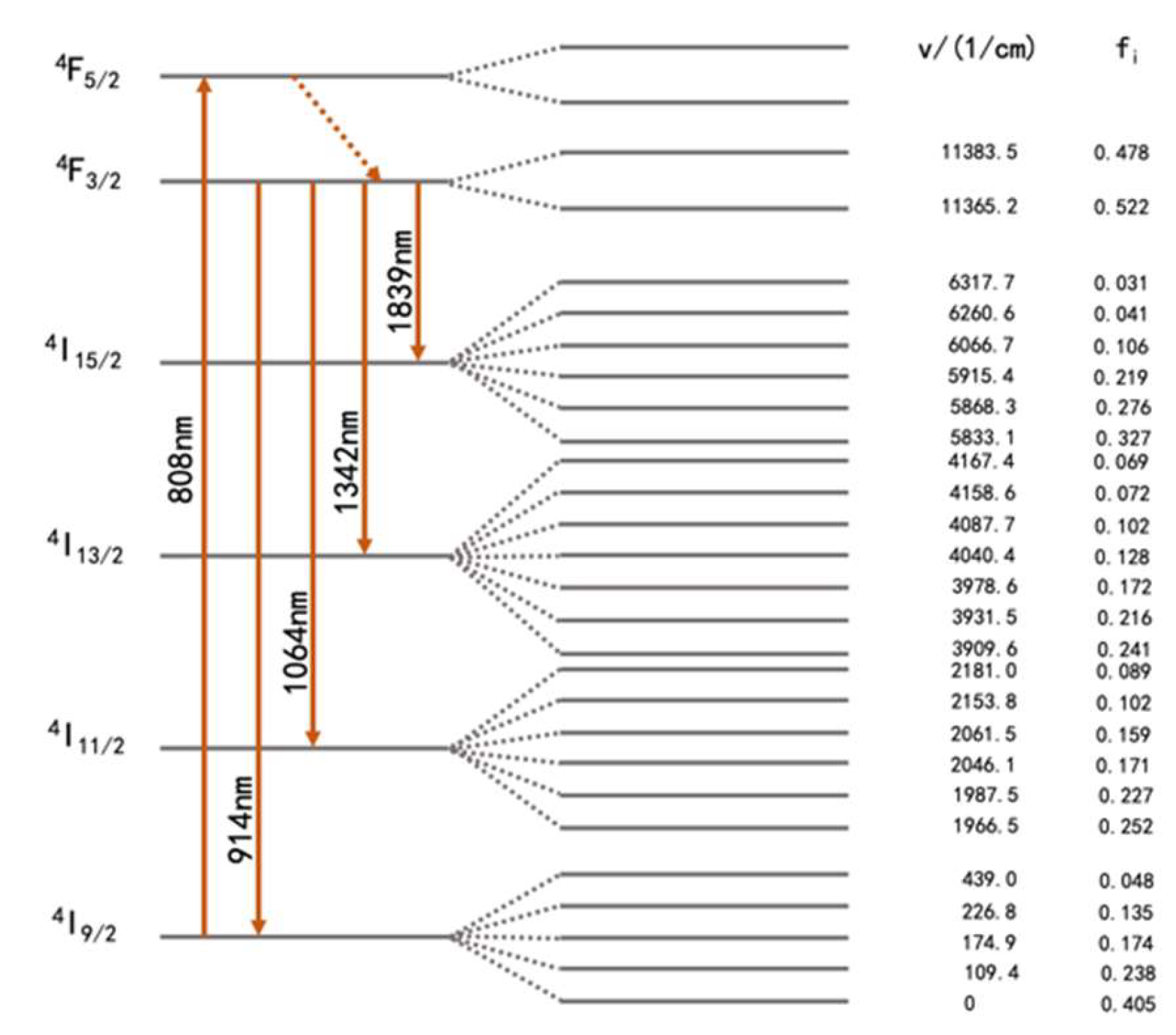
Figure 2.
Axial structure of the Nd:YVO4 crystal in our study.
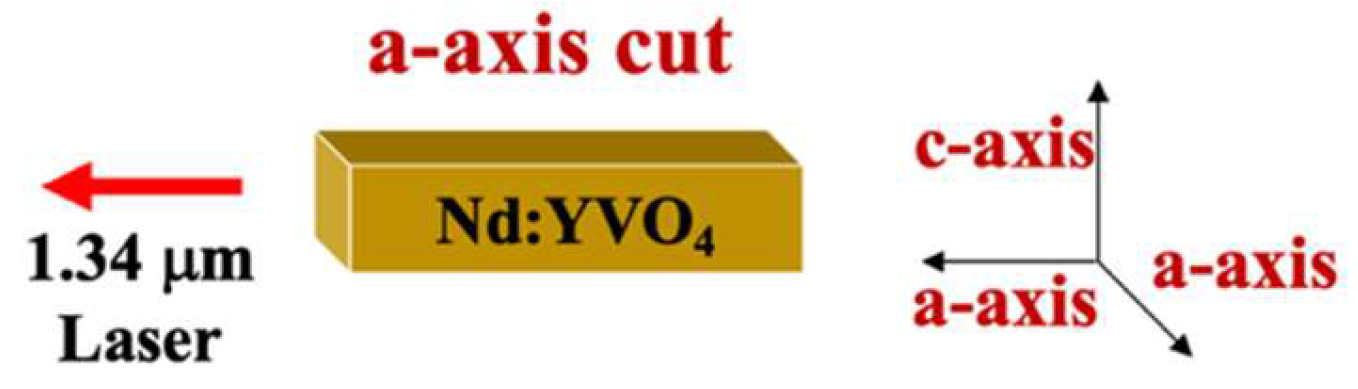
Figure 3.
Schematic illustration of the experimental setup.
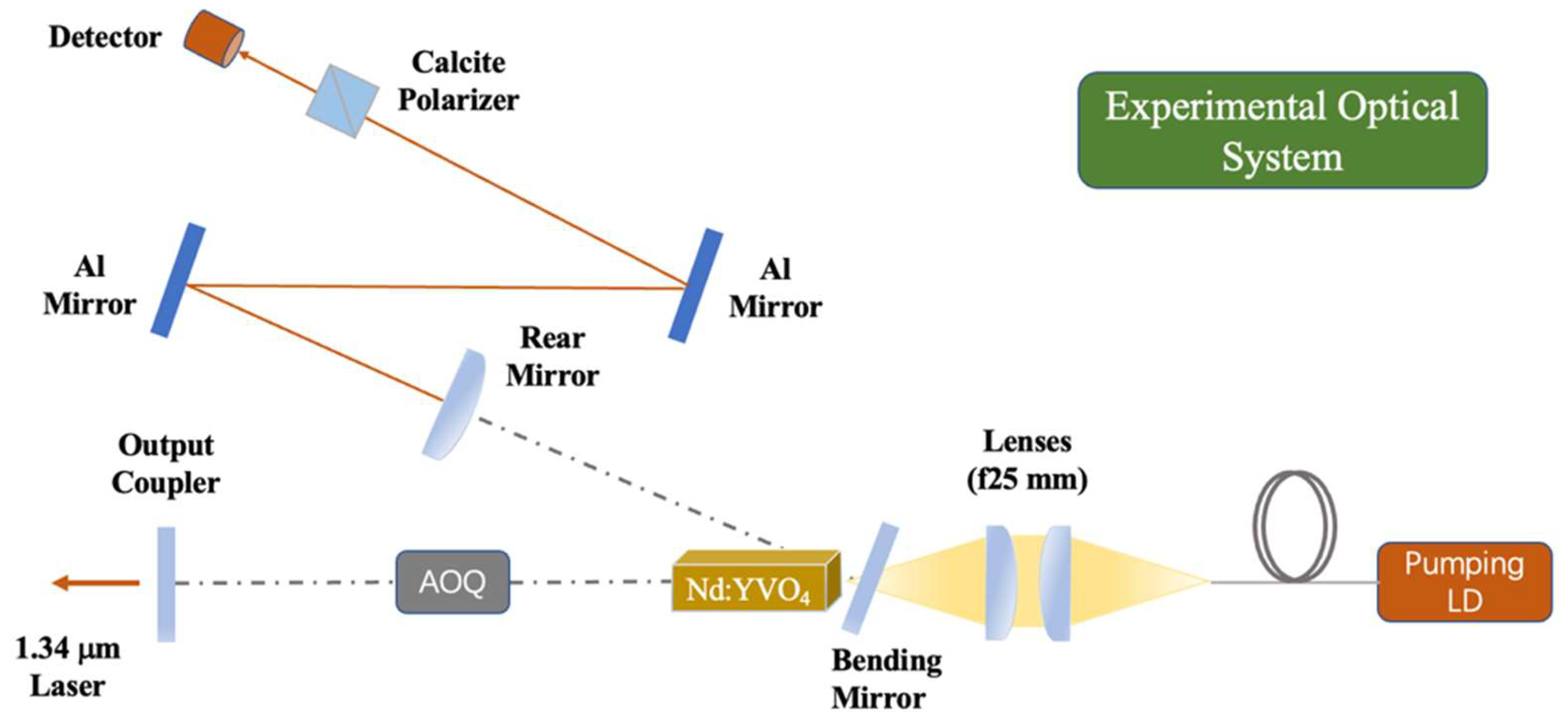
Figure 4.
Gate signal and RF signal in our experiment.
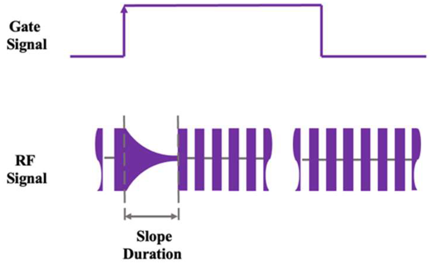
Figure 5.
(a) When slope duration=5.0 μs, a vertical polarizer is added to the output end of the laser. (b) Adjust slope duration to 16.0 μs. (c) Adjust slope duration to 28.0 μs. (d) Adjust slope duration to 100.0 μs. (e) Adjust slope duration to 0.18 ms (f) Adjust slope duration to 0.75 ms.
Figure 5.
(a) When slope duration=5.0 μs, a vertical polarizer is added to the output end of the laser. (b) Adjust slope duration to 16.0 μs. (c) Adjust slope duration to 28.0 μs. (d) Adjust slope duration to 100.0 μs. (e) Adjust slope duration to 0.18 ms (f) Adjust slope duration to 0.75 ms.
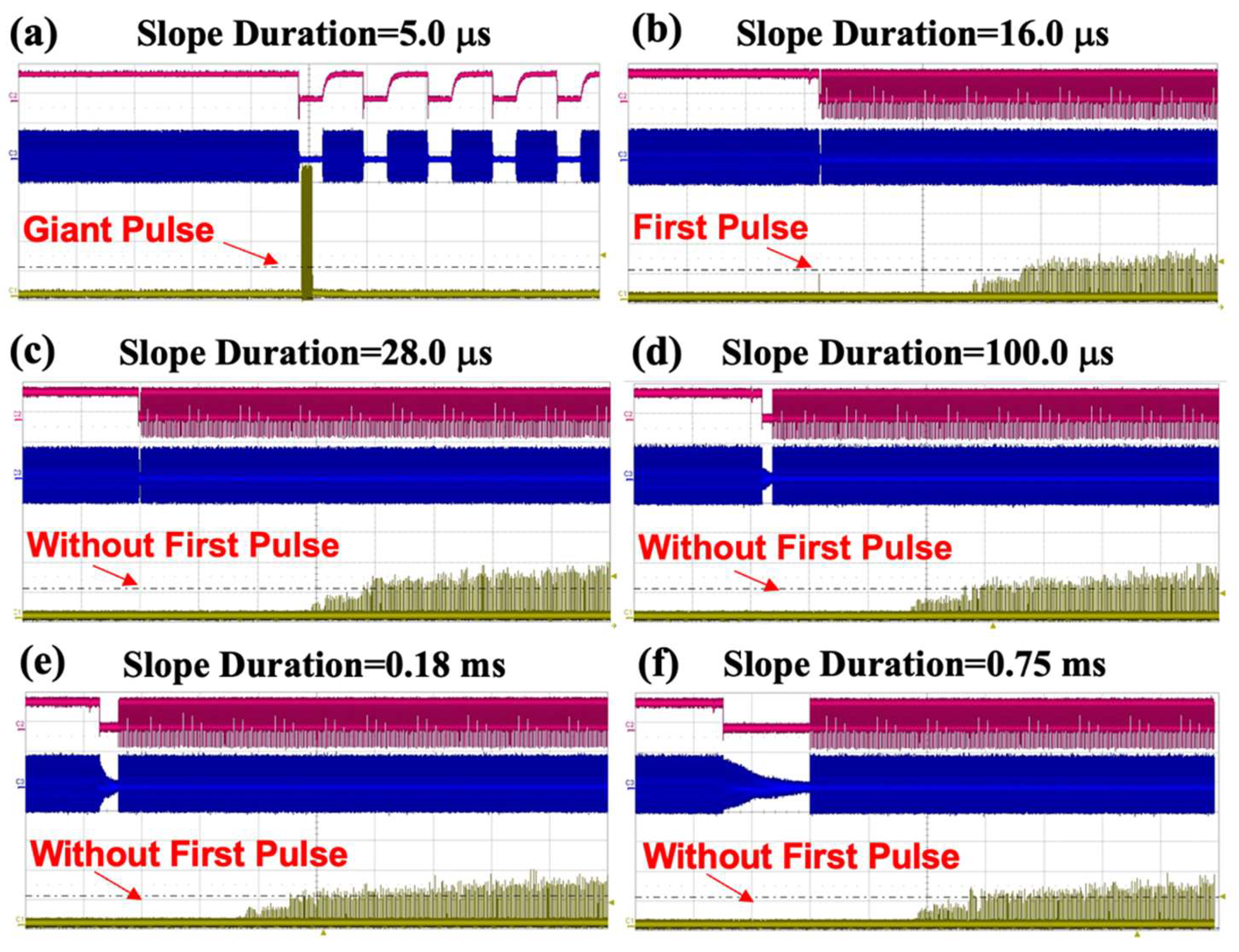
Figure 6.
Slope duration of RF signals versus the giant pulse intensity along the vertical polarized direction.
Figure 6.
Slope duration of RF signals versus the giant pulse intensity along the vertical polarized direction.
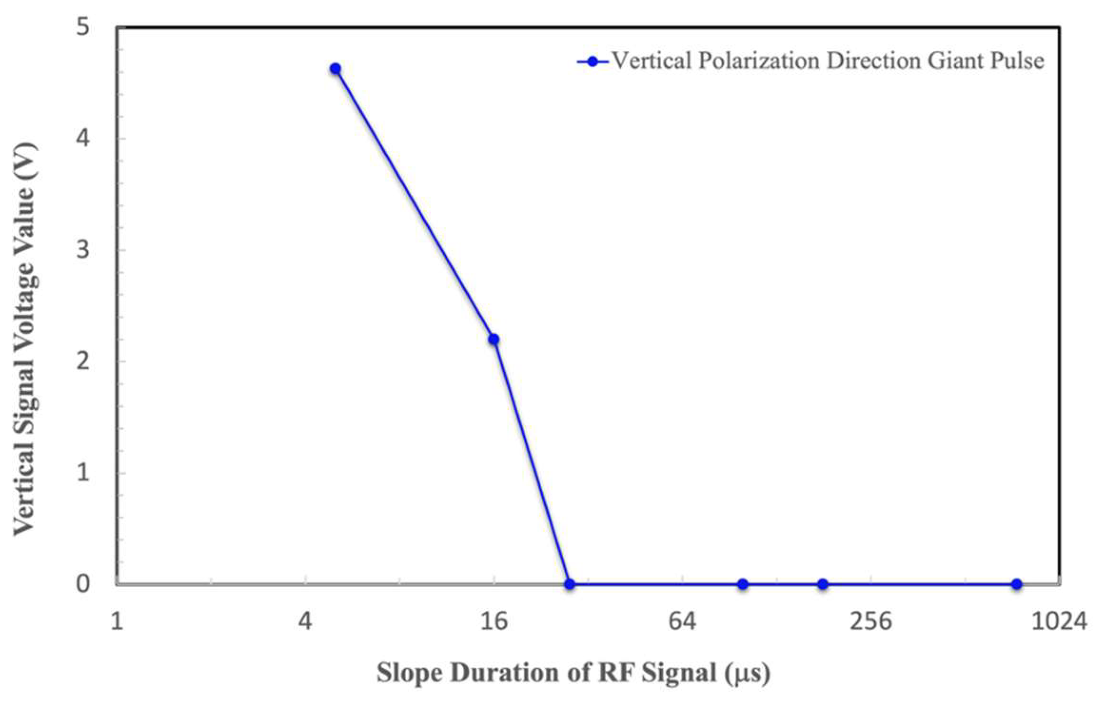
Figure 7.
(a) When slope duration=5.0 μs, a horizontal polarizer is added to the output end of the laser. (b) Adjust slope duration to 28.0 μs. (c) Adjust slope duration to 0.18 ms. (d) Adjust slope duration to 2.0 ms. (e) Adjust slope duration to 5.0 ms. (f) Adjust slope duration to 13.7 ms. (e)(f) are 5 times magnification.
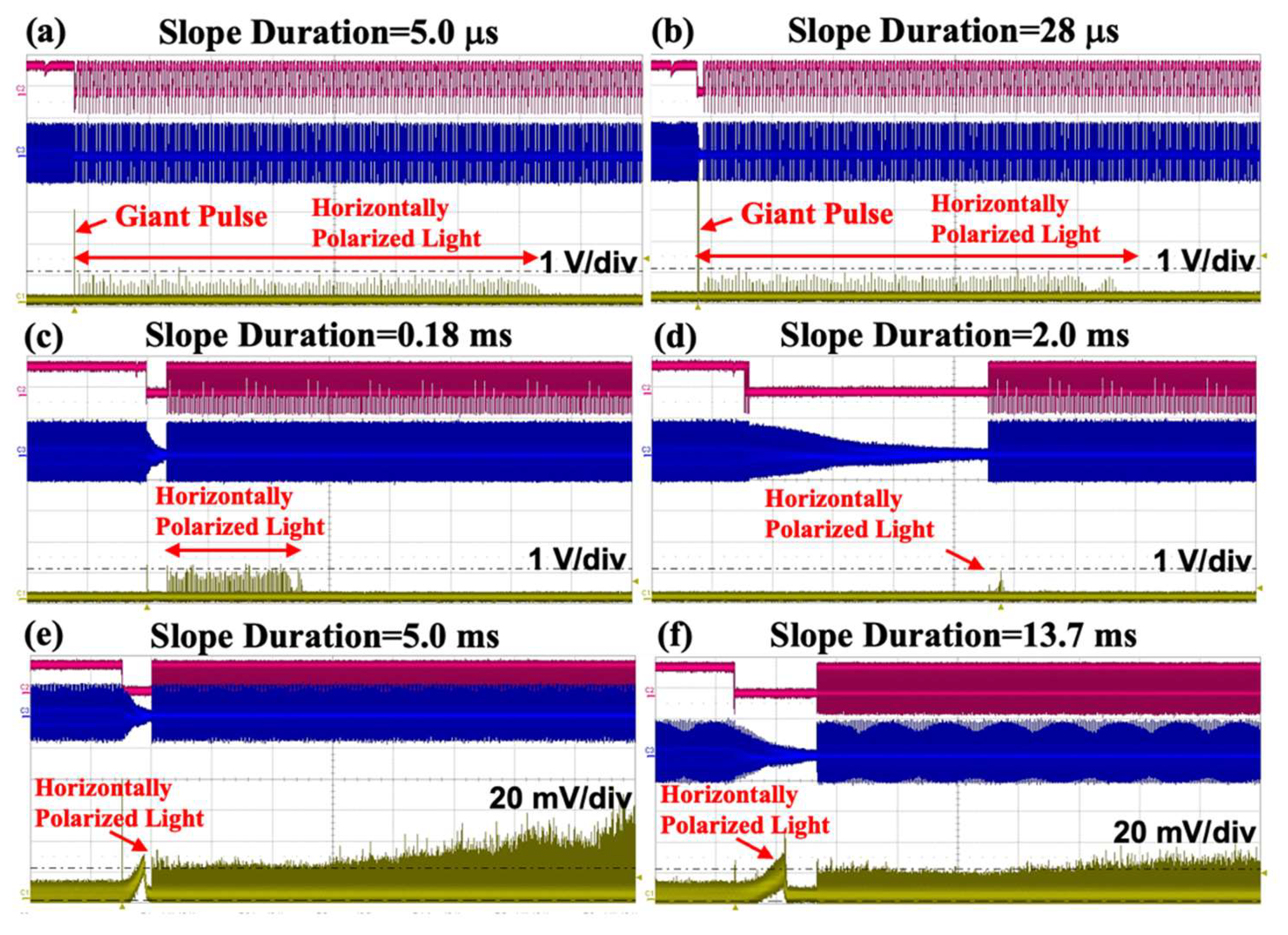
Figure 8.
Giant pulse and the abnormal output lasing emission along the horizontal polarized direction versus the slope duration of RF signals.
Figure 8.
Giant pulse and the abnormal output lasing emission along the horizontal polarized direction versus the slope duration of RF signals.
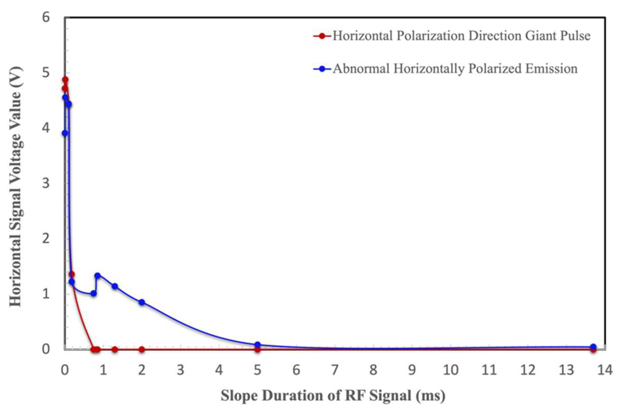
Figure 9.
Relationship between focal length of thermal lens and average pump power.
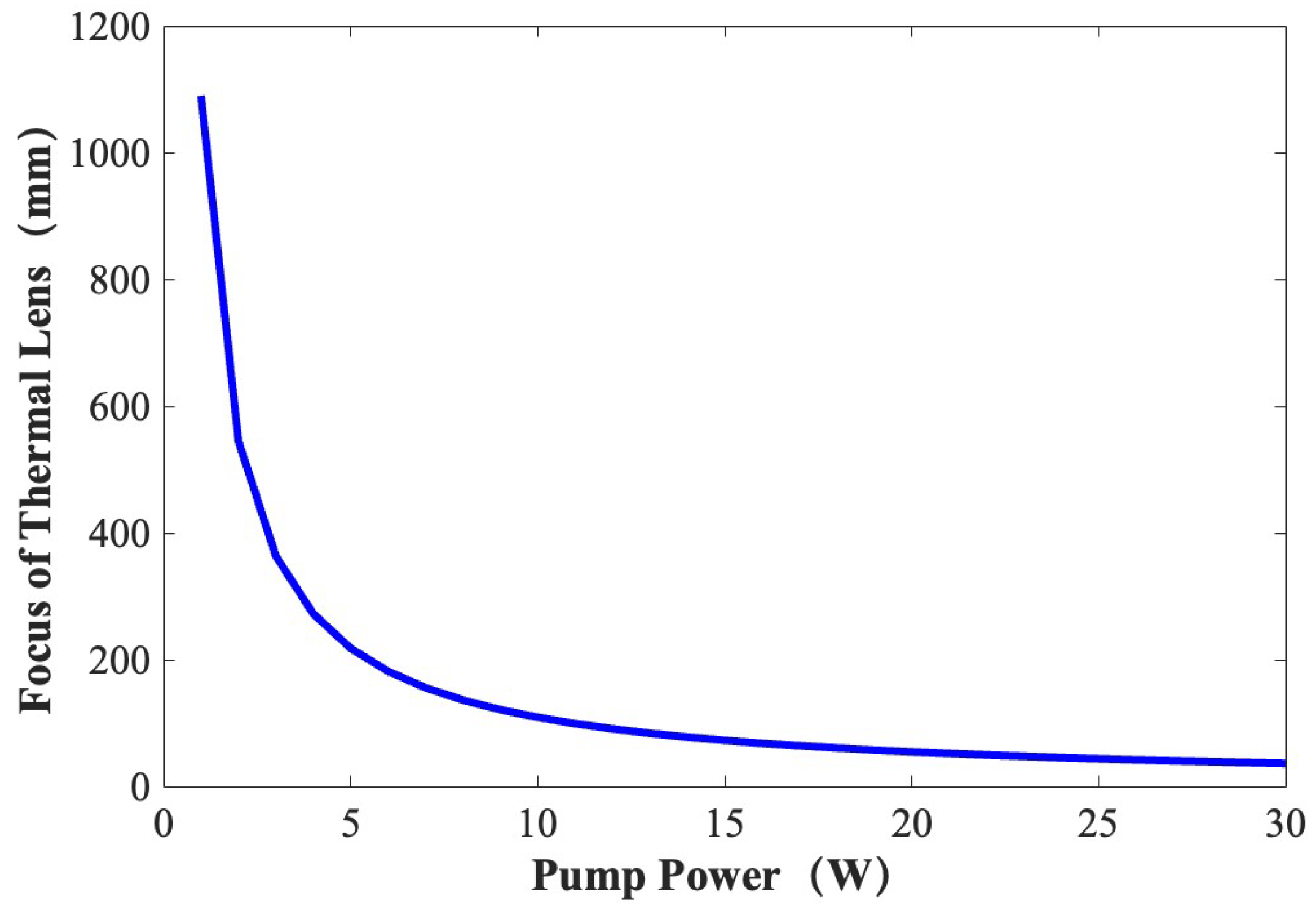
Figure 10.
Schematic diagram of a Nd:YVO4 laser resonator.
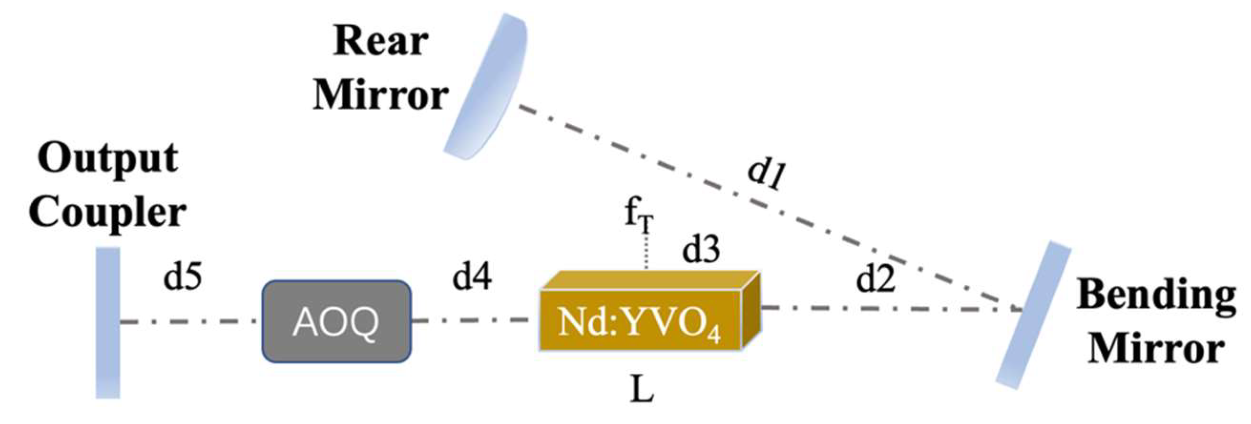
Figure 11.
Radius of a fundamental beam at the RM versus the focal length of a thermally-induced lens of the Nd:YVO4 crystal in our study.
Figure 11.
Radius of a fundamental beam at the RM versus the focal length of a thermally-induced lens of the Nd:YVO4 crystal in our study.
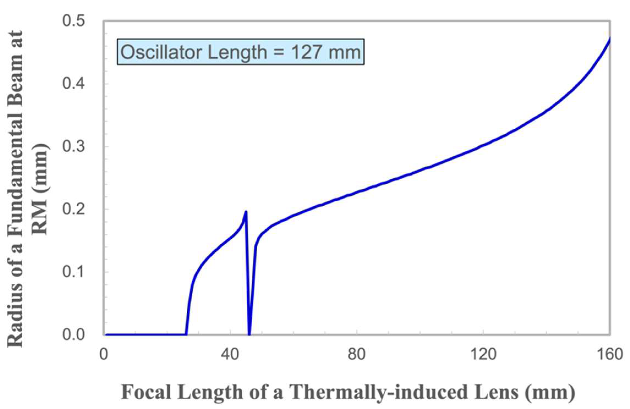
Figure 12.
Relationship between the slope duration of the RF signal and the generation of the giant pulse and horizontally polarized emission.
Figure 12.
Relationship between the slope duration of the RF signal and the generation of the giant pulse and horizontally polarized emission.
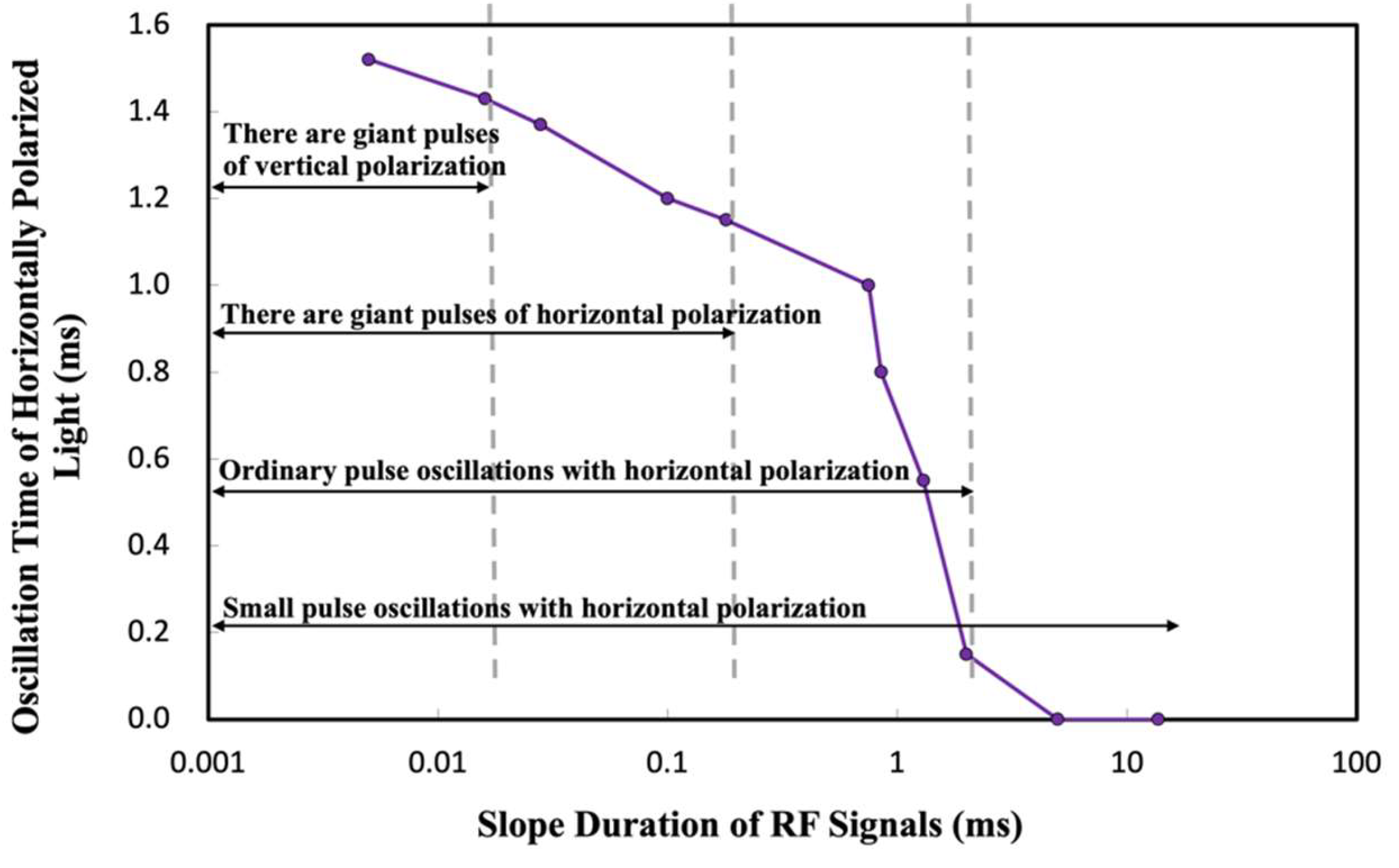

Table 1.
Parameter Values in the Thermal Lens Formula.
| 5.4*10^-3 (W/cm*K) | 300*10^-3 (mm) | 4.67*10^-6 (1/K) | 1.48 (1/mm) | 10 (mm) | 0.3 |
Disclaimer/Publisher’s Note: The statements, opinions and data contained in all publications are solely those of the individual author(s) and contributor(s) and not of MDPI and/or the editor(s). MDPI and/or the editor(s) disclaim responsibility for any injury to people or property resulting from any ideas, methods, instructions or products referred to in the content. |
© 2024 by the authors. Licensee MDPI, Basel, Switzerland. This article is an open access article distributed under the terms and conditions of the Creative Commons Attribution (CC BY) license (http://creativecommons.org/licenses/by/4.0/).
Copyright: This open access article is published under a Creative Commons CC BY 4.0 license, which permit the free download, distribution, and reuse, provided that the author and preprint are cited in any reuse.


