Submitted:
04 July 2024
Posted:
05 July 2024
You are already at the latest version
Abstract
In this letter, we propose a pattern-diversity antenna with different radiation patterns at two different frequency bands (f1 and f2) (f1: broadside radiation pattern, f2: conical radiation pattern). The proposed structure consists of a central circular antenna and two annular ring antennas; each of the three antennas has individual ports. Two of the ports exhibit orthogonal broadside radiation patterns; the other two ports exhibit orthogonal conical radiation patterns. Thus, they have polarization diversity characteristics. To improve isolation between ports, the inner part of the annular ring antennas is shorted via array, and the outermost port is positioned orthogonal to the other ports. Using this configuration, the isolation between ports was measured as -26.7 dB and -30.1 dB at the two frequency bands, respectively. Experimental results based on the fabricated prototype show that the proposed antenna achieves -10 dB bandwidths of 240 MHz (5.71~5.95 GHz) and 210 MHz (7.69~7.9 GHz) at f1 and f2, respectively.
Keywords:
High isolation
; Pattern-diversity antenna
; Polarization diversity
1. Introduction
Dual-Band antennas enable simultaneous use of two communication links with a single antenna. Additionally, when applied to GPS systems, dual-band technology can provide improved accuracy compared to using a single frequency. By incorporating additional frequency bands, dual-band antennas can enhance data quality and connection success rates, overcoming the limitations of using a single frequency band [1].
There are two main methods for implementing dual-band antennas. One approach involves positioning two or more independent antennas closely together to create a dual-band antenna [2,3] another method is to use a single antenna [4,5,6,7]. The former method of placing multiple independent antennas adjacent to each other is becoming less popular due to the relatively large size. Dual-band antennas with a single resonator use substrate-integrated waveguide (SIW) technology [4,5] or using diplexing methods [6,7]. These methods share the same structure and can be seamlessly integrated into a common design. However, the frequency ratio is small.
A radiation pattern indicates the directionality and strength of the signal being transmitted. Antennas have their own unique radiation patterns; a radiation pattern is selected based on the usage requirements. Radiation pattern diversity is a key technology in systems such as multiple-input–multiple-output (MIMO) antennas. Using different radiation patterns, we can increase data transmission rates, mitigate interference, and minimize the impact of multipath effects [8].
Many studies have implemented radiation-pattern diversity. A single port can be used to obtain different radiation patterns at multiple frequency bands. This has been achieved using antennas based on artificial magnetic conductors (AMCs) [9] or applying spiral inverted-F antennas [10]. Multiple ports at specific frequencies can be used to achieve different radiation patterns. Given isolation between ports, methods that arrange ports vertically [12] or use annular ring antennas with shorted inner parts have been used [13]. Furthermore, combination of inductive loaded patches and annular ring antennas has been used to diversify radiation patterns and polarization [14]. Multiple ports at different frequency bands can be used to obtain different radiation patterns. This can be achieved by aligning the centers of circular antennas and annular ring antennas [15]. In another method, a sequentially rotated microstrip feed is used for the high band and four open-ended slots are used for an omni-directional pattern in the low band [16]. Shielded mushroom structures in artificial transmission lines (ATLs) have been used to implement dual-band triple-mode antennas [17].
In this research, we achieved dual-band characteristics using a circular antenna and an annular ring antenna with its inner part shorted via an array. We obtained two different radiation patterns at two frequency bands and simultaneously obtained identical but orthogonal radiation patterns at the same frequency band. In Table I, we compare the performance of the proposed antenna with previously published dual-band microstrip antennas. The presented metrics are simulation results obtained using HFSS. The measured data were obtained through experiments conducted with fabricated prototypes.

Table 1.
Comparison with previous dual-feed dual-cp antennas.
| Ref. | Freq. [GHz] |
BW [%] | Size | # of port |
Iso. [dB] |
Pattern |
|---|---|---|---|---|---|---|
| [2] | 5.8/ 30 | 3.1/ 8.1 17/ 6.3 |
1.90 1.90 0.020 | 2 | O/ B | |
| [4] | 5.2/ 5.8 | 6/ 3.4 | 1.50 1.30 0.038 | 2 | B/ B | |
| [5] | 8.3/ 10.5 | 1.9/ 2.7 | 0.88 0.72 0.040 | 2 | B/ B | |
| [6] | 2.5/ 5.3 | 4.5/ 5.5 | 0.57 0.57 0.010 | 2 | B/ B | |
| [7] | 2.5/ 5.5 | 1.3/ 3 | 0.20 0.10 0.014 | 2 | O/ O | |
| [9] | 1.4/ 1.6 | 2/ 1 | 0.57 0.57 0.030 | 1 | X | O/ B |
| [10] | 2.5/ 5.8 | 4/ 3.4 | 0.30 0.30 0.080 | 1 | X | O/ B |
| [12] | 3.5 | 1.4 | 0.35 0.35 0.035 | 3 | O/ B/ B | |
| [13] | 5.8 | 2.5 | 0.96 0.96 0.030 | 2 | O / B | |
| [15] | 2.4/ 5.8 | 0.9/ 2 2/ 1.8 |
0.28 0.28 0.012 | 2 | O/ B | |
| [16] | 2.5/ 5.9 | 8.1/ 10.3 | 0.40 0.40 0.035 | 2 | O/ B | |
| [18] | 2.5/ 3.5 | 1/ 1.6 6.7/ 1.2 |
0.90 0.90 0.060 | 2 | B/ O | |
| This work | 5.9/ 7.9 | 3.6/ 3.6 1.5/ 2.1 |
0.49 0.49 0.030 | 3 | B/O |
2. Antenna Configuration
Figure 1 shows the configuration of the proposed antenna. The substrate used in the design is RO4003C with a thickness of 1.58 mm, a dielectric constant of 3.55, and a loss tangent of 0.0027. The proposed antenna consists of one circular antenna and two annular ring antennas shorted via an array. The radii of the vias located inside are 0.27 mm; the radii of the vias located outside are 0.6 mm. The outermost ring antenna (Antenna I), has outer and inner radii denoted as r1 and r2, respectively. Antenna II is positioned with outer and inner radii denoted as r3 and r4, respectively. In the center, there is a circular antenna with a radius of r5 (Antenna III). The ground radius is set to r0. The positions of the ports are determined by d1, d2, and d3.
Antennas 2 and 3 are positioned inside the ring structure of Antenna I, allowing the antennas to achieve different radiation patterns (broadside radiation pattern and conical radiation pattern) at two different frequency bands without increasing the size of the antenna. To enhance isolation between ports, vias are incorporated into the structure; Antenna I has 30 vias and Antenna II has 60 vias. Antennas 1 and 3 form a broadside radiation pattern at 5.93 GHz in the TM11 mode; Antennas 1 and 2 form a conical radiation pattern at 7.92 GHz in the TM41 and TM21 modes, respectively. Port 1 is positioned orthogonal to Ports 2 and 3 for good isolation. Furthermore, the vias located on the outer side improve the isolation characteristics between antennas.
The resonant frequencies of the TM modes of the proposed antennas can be determined using (1) [19,20].
In this equation, nm is related to the TMnm mode; c represents the speed of light, and εr denotes the dielectric constant of the substrate. ae denotes the effective radius, which can be obtained using (2). Xnm is the root of (3); its values are X11=1.8412, X21=1.3406, and X41=2.5876 [21].
In (2), a represents the radius for a circular antenna and the inner radius for a ring antenna; h denotes the height of the substrate. Equation (3) is derived from the boundary conditions of the cavity mode for these antennas. Here, g is the ratio of the outer radius to the inner radius, and Jn and Nn denote the nth order Bessel functions of the first and second kind, respectively, where the prime notation indicates the first derivative.
3. Parameter Study
A. Isolation Based on Port Positions
Figure 2(a) shows the antenna configurations corresponding to different port positions. Antenna I shows three ports aligned in a straight line. Antenna II shows a 90° rotation of port 2. Antenna III shows a 90° rotation of port 1. Antenna IV shows a 90° rotation of ports 1 and 2. The antenna parameters except for the port positions are set as follows. The antenna dimensions are: . The radius of the via for Antenna I is 0.6 mm, and for Antenna II is 0.27 mm. The positions of the three ports in the proposed structure are set as follows: . Figure 2(b) presents the simulation results for isolation as the antenna ports are rotated by 90°. Figure 2(c) and 2(d) show the simulation results for isolation at frequencies of 5.93 GHz and 7.92 GHz, respectively. From the simulation results, when port 1 and port 3 are perpendicular to each other, the isolation characteristics are good.
In Figure 2(c), the isolation between port 1 and port 3 of each model at the 5.9 GHz band is -13 dB (Antennas I and II, where the two ports are horizontal). In comparison, Antennas III and IV, where the two ports are perpendicular, show an improved isolation of approximately -30 dB. Port 2 does not significantly influence the isolation characteristics based on its position relative to the other two ports. In Figure 2(d), comparing the S21 at 7.92 GHz, all three antenna models exhibit isolation values of approximately -30 dB. Based on these results, Antenna III was selected to enhance the isolation characteristics between the antenna ports.
B. Effect of Number of Vias
According to [22], adjusting the number of vias in the antenna can control the resonant frequencies corresponding to each TM mode and can adjust the bandwidth or separate the bands.
Figure 3(a) shows the simulation results with different reflection coefficients based on the number of vias located on Antenna I to observe the change in the angle between the vias. The angle between the vias was set to 5°, 12°, and 15°; all other antenna parameters were kept constant. From Figure 3, there is not a significant difference in performance based on the number of vias in S33. However, for S11, as the angle between the vias increases (with fewer vias), the resonant frequency decreases, indicated by the green diamonds in Figure 3(a). With an angle of 12°, there is a wider bandwidth below -10 dB than with angles of 5° and 15°. For S22, it is also evident that a 12° angle provides the widest bandwidth below -10 dB. Based on these results, the angle between the vias was set to 12°.
C. Effect of Antenna Size
Figure 4 shows the simulation results for reflection coefficients and isolation characteristics with different lengths r1. The length of r1 was increased from 21 mm in 0.5-mm increments; all other antenna parameters were kept constant. In Figure 4(a), it is observed that there is no significant performance difference in S22 with changes in the size of r1. However, for S11, as r1 increases (as the size of Antenna I increases), the resonant frequency decreases, as indicated by the green diamonds in Figure 4(a). For S33, there is no bandwidth below -10 dB with a size of 21 mm; with a size of 22 mm, the bandwidth is much narrower than with a size of 21.5 mm. Based on these results, the radius r1 of Antenna I was set to 21.5 mm.
Figure 5 shows the simulation results for reflection coefficients and isolation characteristics with different values of r3. The length of r3 was increased from 13.8 mm in 0.1-mm increments; all other antenna parameters were kept constant. In Figure 5(a), it is observed that r3 does not have a significant effect on S11 and S33. However, for S22, as r3 increases (as the size of Antenna II increases), the resonant frequency decreases, indicated by the green diamonds in Figure 5(a). Based on these results, the radius r3 was set to 13.97 mm and the isolation values for each operating band were all below -20 dB.
Figure 6 shows the simulation results for reflection coefficients and isolation characteristics with different values of r5. r5 was increased from 7.25 mm in 0.2-mm increments; all other antenna parameters were kept constant. In Figure 6(a), it is observed that there is no significant performance difference in S22 with changes in the size of r5. Although there are some variations in the resonant frequency and reflection coefficient values for S11, they are not significant. However, for S33, as r5 increases, the resonant frequency decreases, indicated by the green diamonds in Figure 6(a). Additionally, the bandwidth below -10 dB was widest when the size was 7.45 mm. Based on these results, the radius r3 was set to 13.9 mm. At this size, the isolation values for each operating band were all below -20 dB.
4. Simulated and Measured Results
Figure 7 shows a photograph of the proposed antenna, fabricated using the optimized parameters. Figure 8 compares the simulated and measured reflection coefficients and isolation characteristics of the proposed antenna. The bandwidth of -10 dB for the two frequency bands is shown in Figure 8(a). For f1, the common bandwidth between port 1 and port 3 is from 5.71–5.95 GHz, resulting in a bandwidth of 210 MHz. Figure 8(b) shows the isolation characteristics for the ports at each resonant frequency. The isolation between port 1 and port 2 is approximately -35.5 dB. The measured results also confirm good isolation between the ports. The resonant frequencies were shifted approximately 150 MHz lower than the simulated results. This discrepancy was caused by slight variations in the patch antenna dimensions during fabrication.
Figure 9 shows the electric field formed on the antenna surface as RF power is applied to different ports at resonant frequencies. The regions closer to red indicate stronger electric fields; regions closer to blue indicate weaker fields. Figure 9(a) shows the simulation results for the E-field when RF power is applied to port 1 at 5.93 GHz. The electric field along the horizontal axis where port 3 is located becomes null, indicating that the ports do not influence each other. Similarly, Figure 9(b) shows the simulation results when power is applied to port 3 at 5.93 GHz. The electric field along the vertical axis where port 1 is located becomes null, indicating no influence between the ports. As shown in Figure 9(c) and 9(d), the electric field is very weak at ports other than the one where power is applied, indicating no influence. Based on the simulation results, it can be concluded that the proposed antenna exhibits excellent isolation characteristics.
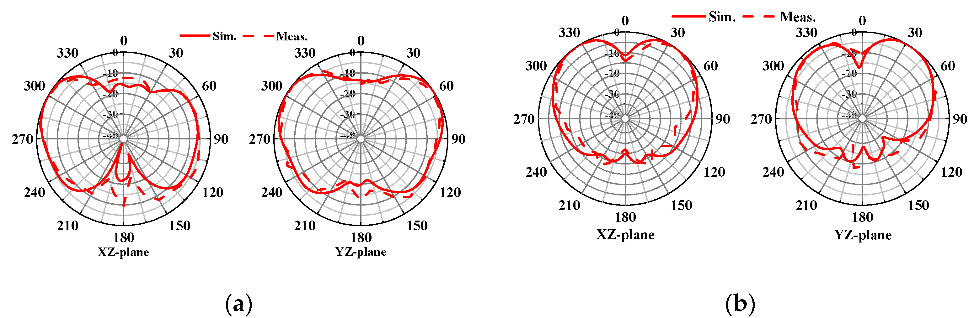
Figure 10 compares the measured radiation patterns of the proposed antenna with the simulated results. In Figure 10(a) and 10(b), at 5.93 GHz, broadside patterns are formed at ports 1 and 3, with energy radiated in the +z-axis direction. At 7.92 GHz, conical patterns are formed at ports 1 and 2, as shown in Figure 11(a) and 11(b). The measured results closely match the simulated values, indicating similar characteristics. The measured antenna gains are approximately 8.2 dBi for port 1 and 8.8 dBi for port 3 at 5.93 GHz. At 7.92 GHz, the gains are approximately 4.9 dBi for port 1 and 6.9 dBi for port 2.
5. Conclusions
In this letter, we propose an antenna with both pattern and polarization diversity. We implement a pattern-diversity antenna with different radiation patterns in two different frequency bands. The proposed antenna consisted of one circular antenna and two ring antennas with the inner section shorted via an array. Each antenna used a feeding method using probes. To improve isolation between ports, each port was designed to be orthogonal. As a result, the isolation between ports was -26.7 dB and -30.1 dB at the two frequency bands, respectively. Based on its excellent isolation characteristics, the proposed antenna exhibits broadside radiation pattern characteristics at f1 and conical radiation pattern characteristics at f2, perpendicular to each other. Thus, we believe that the proposed antenna has potential for multi-band mobile communication applications.
References
- Nandigama, S.V.; Kunooru, B.; Ramakrishna, D.; Pandharipande, V.M. Pattern similarity and gain enhancement of dual-band antenna using an ENZ metamaterial. Journal of Electromagnetic Engineering and Science 2023, 23, 461–469. [Google Scholar] [CrossRef]
- Xiang, B.J.; Zheng, S.Y.; Wong, H.; Pan, Y.M.; Wang, K.X.; Xia, M.H. A flexible dual-band antenna with large frequency ratio and different radiation properties over the two bands. IEEE Transactions on Antennas and Propagation 2018, 66, 657–667. [Google Scholar] [CrossRef]
- Guo, Y.Q.; Pan, Y.M.; Zheng, S.Y.; Lu, K. A singly-fed dual-band microstrip antenna for microwave and millimeter-wave applications in 5G wireless communication. IEEE Transactions on Vehicular Technology 2021, 70, 5419–5430. [Google Scholar] [CrossRef]
- Chaturvedi, D.; Kumar, A.; Raghavan, S. A nested SIW cavity-backing antenna for Wi-Fi/ISM band applications. IEEE Transactions on Antennas and Propagation 2019, 67, 2775–2780. [Google Scholar] [CrossRef]
- Nandi, S.; Mohan, A. An SIW cavity-backed self-diplexing antenna. IEEE Antennas and Wireless Propagation Letters 2017, 16, 2708–2711. [Google Scholar] [CrossRef]
- Lee, Y.-J.; Tarng, J.-H.; Chung, S.-J. A filtering diplexing antenna for dual-band operation with similar radiation patterns and low cross-polarization levels. IEEE Antennas and Wireless Propagation Letters 2017, 16, 58–61. [Google Scholar] [CrossRef]
- Lu, Y.-C.; Lin, Y.-C. A mode-based design method for dual-band and self-diplexing antennas using double T-stubs loaded aperture. IEEE Transactions on Antennas and Propagation 2012, 60, 5596–5603. [Google Scholar] [CrossRef]
- Sharawi, M.S. Printed multi-band MIMO antenna systems and their performance metrics [wireless corner]. IEEE Antennas and Propagation Magazine 2013, 55, 218–232. [Google Scholar] [CrossRef]
- Lin, J.; Qian, Z.; Cao, W.; Shi, S.; Wang, Q.; Zhong, W. A low-profile dual-band dual-mode and dual-polarized antenna based on AMC. IEEE Antennas and Wireless Propagation Letters 2017, 16, 2473–2476. [Google Scholar] [CrossRef]
- Zhang, X.Y.; Wong, H.; Mo, T.; Cao, Y.F. Dual-band dual-mode button antenna for on-body and off-body communications. IEEE Transactions on Biomedical Circuits and System 2017, 11, 933–941. [Google Scholar] [CrossRef] [PubMed]
- Zhang, T.; Hong, W.; Zhang, Y.; Wu, K. Design and analysis of SIW cavity backed dual-band antennas with a dual-mode triangular-ring slot. IEEE Transactions on Antennas and Propagation 2014, 62, 5007–5016. [Google Scholar] [CrossRef]
- Piao, D.; Wang, Y. Tripolarized MIMO antenna using a compact single-layer microstrip patch. IEEE Transactions on Antennas and Propagation 2019, 67, 1937–1940. [Google Scholar] [CrossRef]
- Mirhadi, S. Single-layer, dual-port, and dual-mode antenna with high isolation for WBAN Communications. IEEE Antennas and Wireless Propagation Letters 2022, 21, 531–535. [Google Scholar] [CrossRef]
- Yan, S.; Vandenbosch, G.A.E. Wearable antenna with tripolarization capability. 2017 International Workshop on Antenna Technology: Small Antennas, Innovative Structures, and Applications (iWAT), Athens, Greece, 2017, pp. 129–131.
- Liu, Z.G.; Guo, Y.X. Dual band low profile antenna for body centric communications. IEEE Transactions on Antennas and Propagation 2013, 61, 2282–2285. [Google Scholar] [CrossRef]
- Mao, C.-X.; Werner, D.H.; Zhang, Y.; Zhang, X.-Y. Compact dual-band dual-mode antenna with omni-/unidirectional radiation characteristics. IEEE Antennas and Wireless Propagation Letters 2019, 18, 2657–2660. [Google Scholar] [CrossRef]
- Zhang, K.; Jiang, Z.H.; Yue, T.; Zhang, Y.; Hong, W.; Werner, D.H. A compact dual-band triple-mode antenna with pattern and polarization diversities enabled by shielded mushroom structures. IEEE Transactions on Antennas and Propagation 2021, 69, 6229–6243. [Google Scholar] [CrossRef]
- Yan, S.; Zhang, J.; Hu, X.; Vandenbosch, G.A.E. Dual-band CRLH-TL based patch antenna with pattern diversity. 2017 11th European Conference on Antennas and Propagation (EUCAP), Paris, France, 2017, pp. 2956–2959.
- Kaur, I.; et al. Annular ring ultra wideband antenna integrated with metallic via array for IoT applications. IEEE Access 2022, 10, 73446–73457. [Google Scholar] [CrossRef]
- Kapusuz, K.Y.; Lemey, S.; Petrocchi, A.; Demeester, P.; Schreurs, D.; Rogier, H. Polarization reconfigurable air-filled substrate integrated waveguide cavity-backed slot antenna. IEEE Access 2019, 7, 102628–102643. [Google Scholar] [CrossRef]
- Garg, R.; Bhartia, P.; Ittipiboon, A. Microstrip antenna design handbook; Artech house: Boston (Mass.), 2001; pp. 317–324. [Google Scholar]
- Liu, J.; Xue, Q.; Wong, H.; Lai, H.W.; Long, Y. Design and analysis of a low-profile and broadband microstrip monopolar patch antenna. IEEE Transactions on Antennas and Propagation 2013, 61, 11–18. [Google Scholar] [CrossRef]
Figure 1.
Geometry of the proposed antenna.
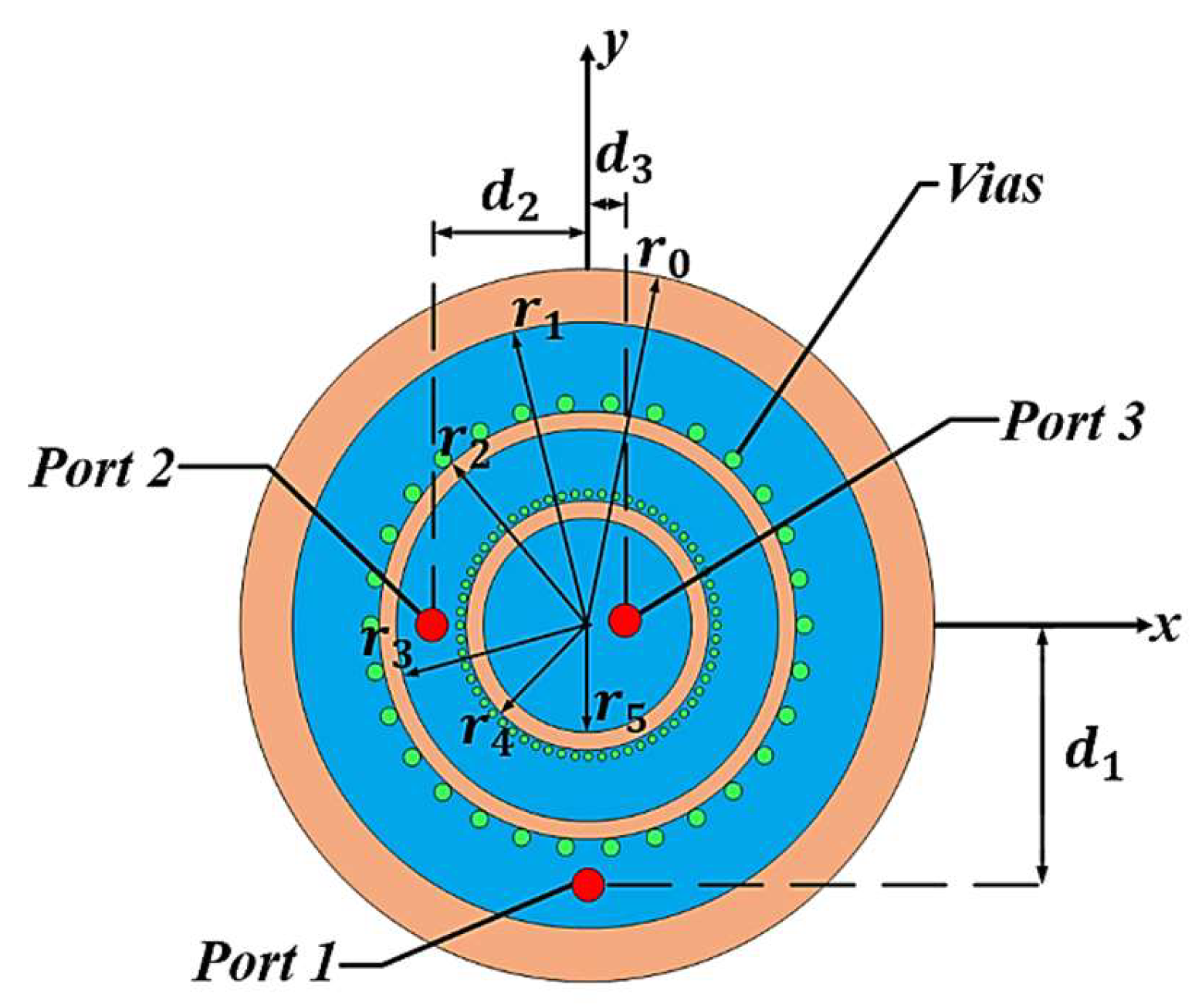
Figure 2.
E-field distribution: (a) at 5.93 GHz_port1; (b) at 7.92 GHz_port1; (c) at 5.93 GHz_port3; (d) at 7.92 GHz_port2. .
Figure 2.
E-field distribution: (a) at 5.93 GHz_port1; (b) at 7.92 GHz_port1; (c) at 5.93 GHz_port3; (d) at 7.92 GHz_port2. .
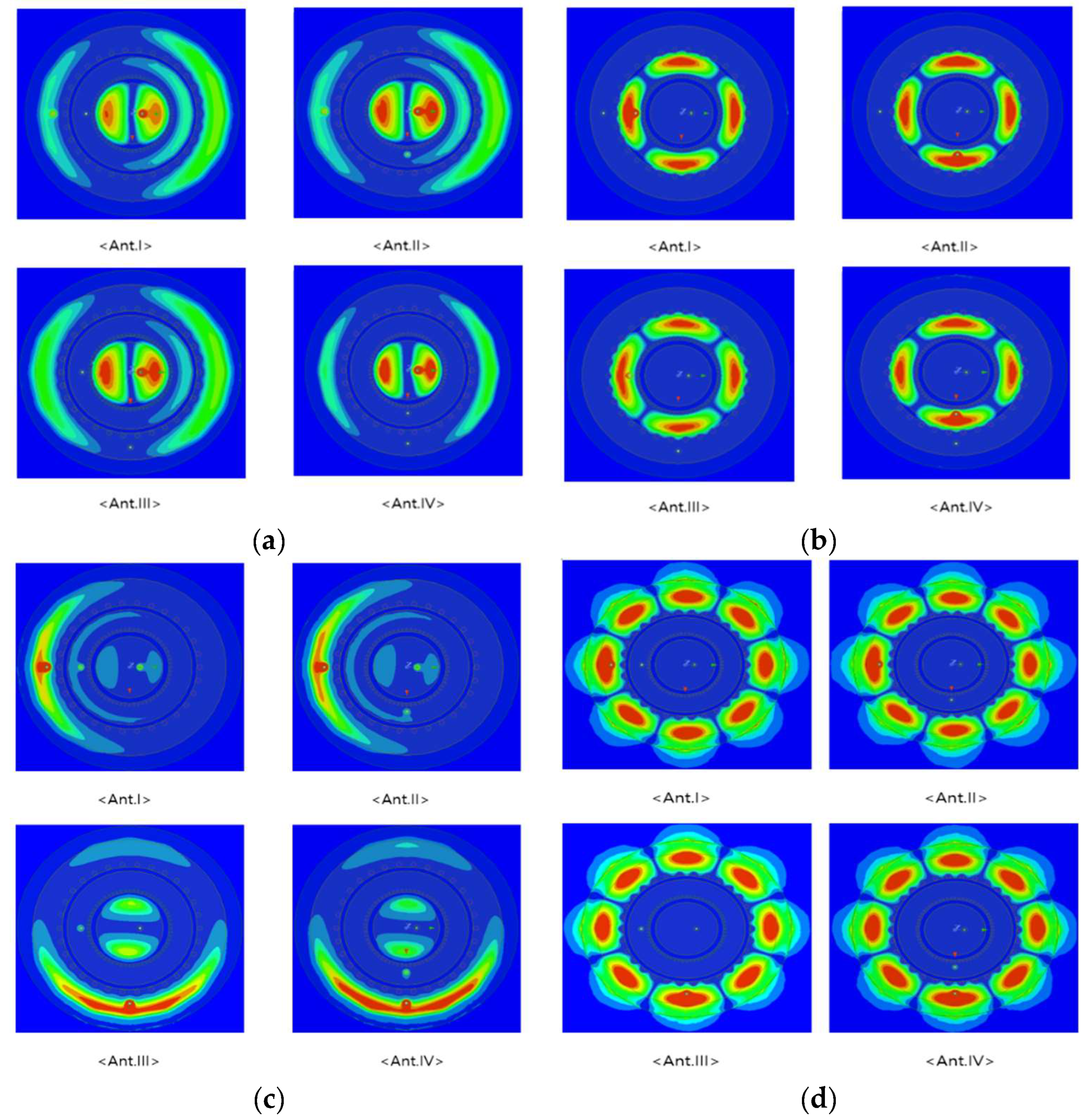
Figure 3.
Simulated antenna performance with different angels(θ) between the vias: (a) Reflection Coefficient; (b) Isolation.
Figure 3.
Simulated antenna performance with different angels(θ) between the vias: (a) Reflection Coefficient; (b) Isolation.
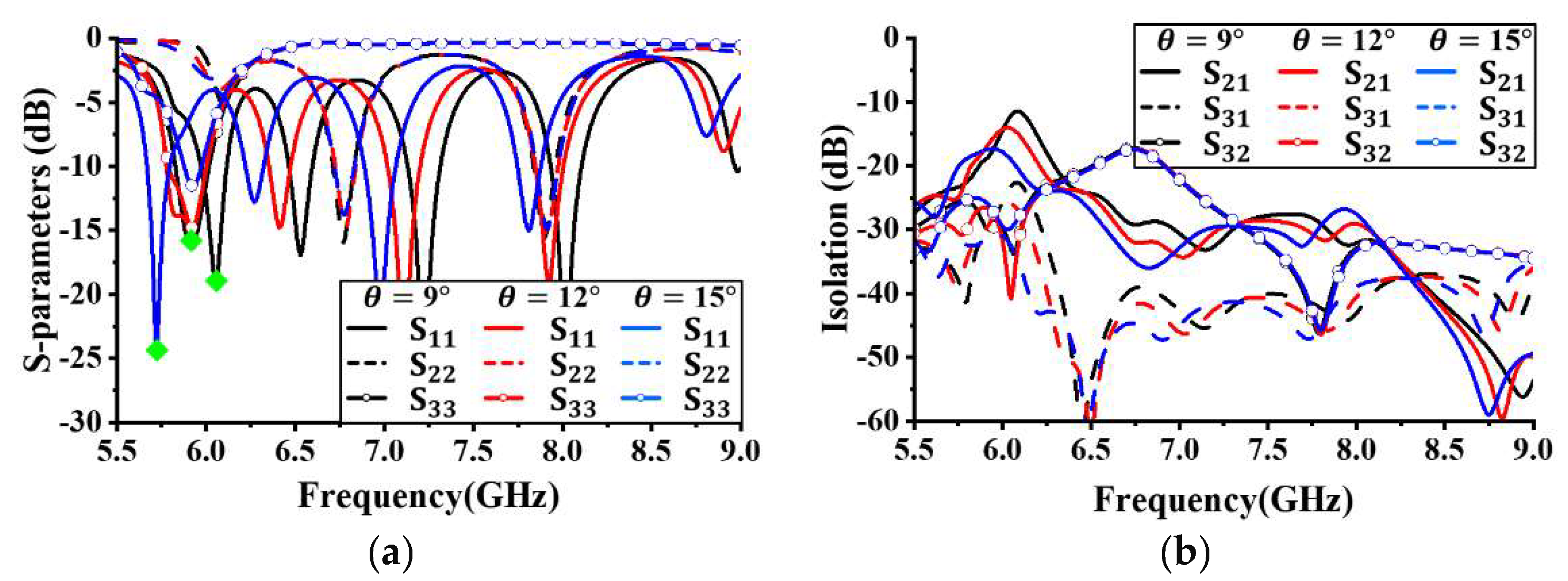
Figure 4.
Simulated antenna performance with different radius r1: (a) Reflection coefficient; (b) Isolation.
Figure 4.
Simulated antenna performance with different radius r1: (a) Reflection coefficient; (b) Isolation.
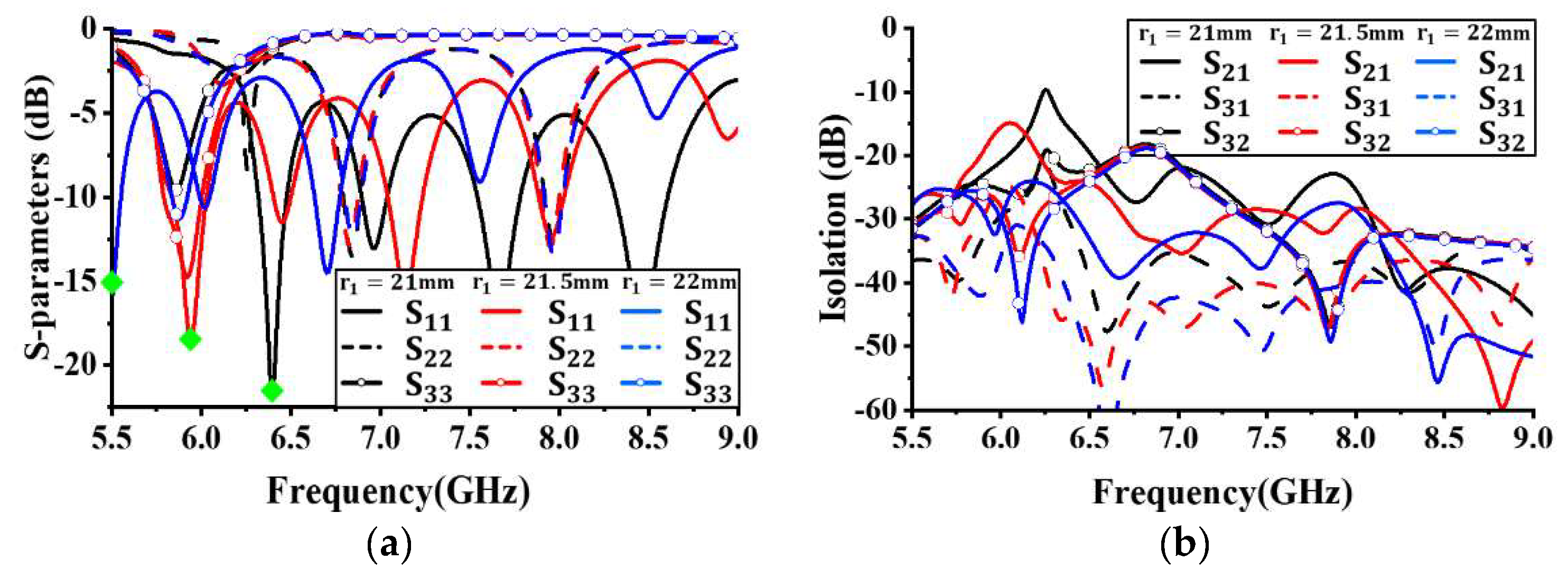
Figure 5.
Simulated antenna performance with different radius r3: (a) Reflection coefficient; (b) Isolation.
Figure 5.
Simulated antenna performance with different radius r3: (a) Reflection coefficient; (b) Isolation.
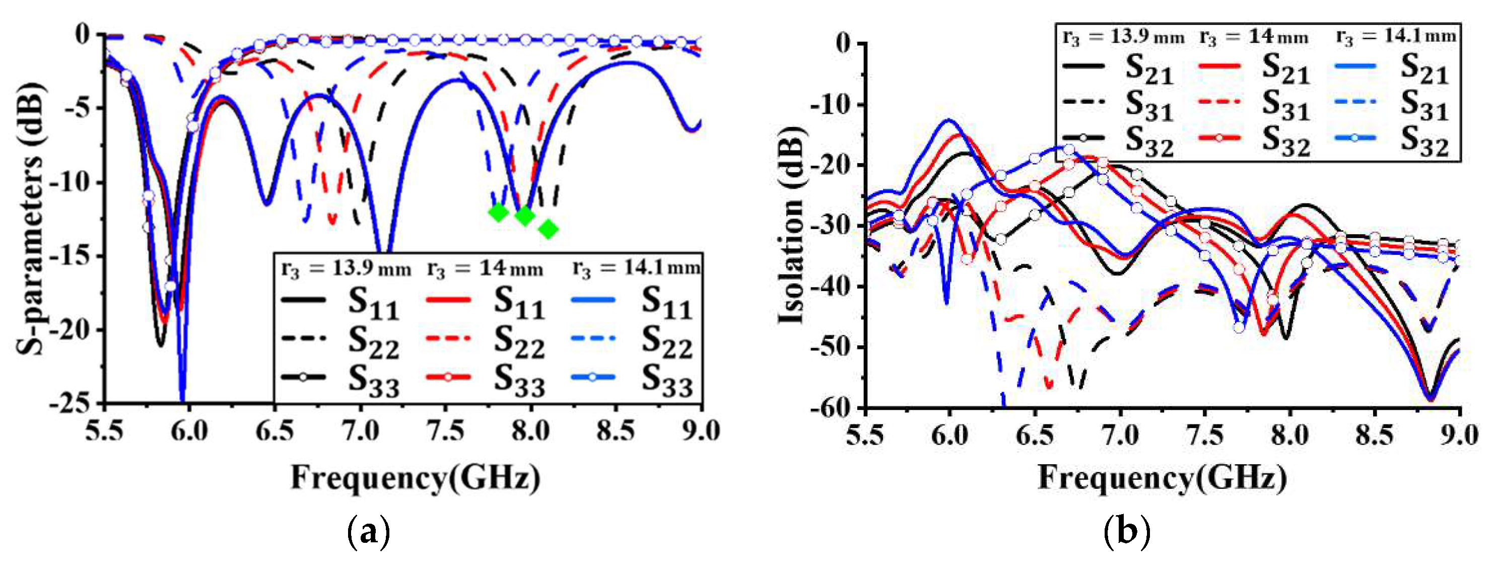
Figure 6.
Simulated antenna performance with different radius r5: (a) Reflection coefficient; (b) Isolation.
Figure 6.
Simulated antenna performance with different radius r5: (a) Reflection coefficient; (b) Isolation.
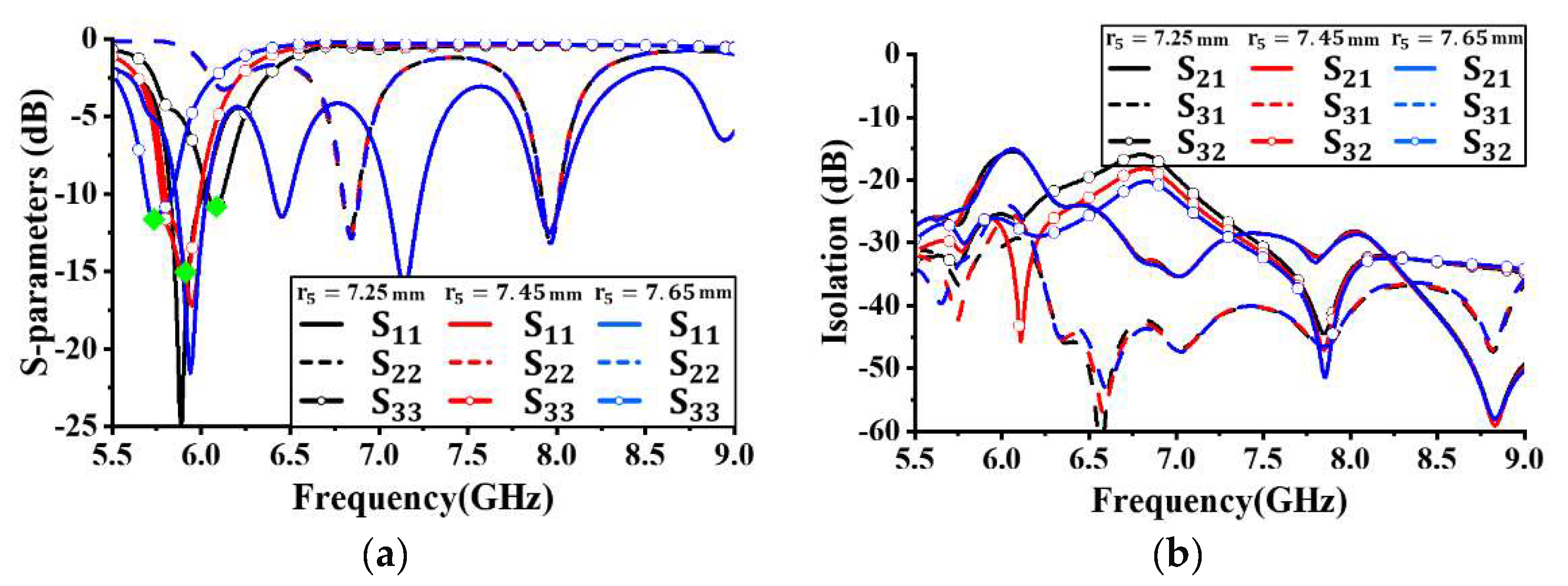
Figure 7.
Prototype of the proposed antenna: (a) Top layer; (b)Bottom layer.
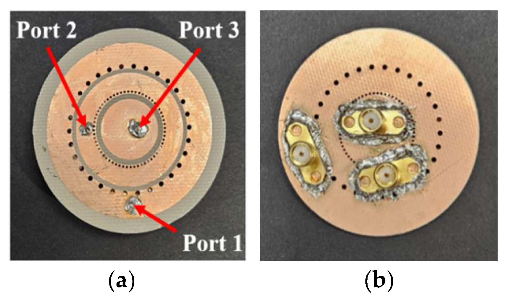
Figure 8.
Simulated and measured results: (a) Reflection coefficient; (b) Isolation.
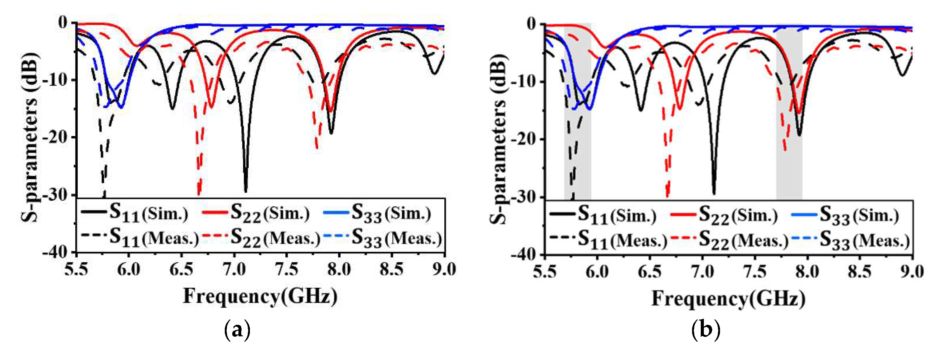
Figure 9.
Simulated E-field distribution: (a) 5.93 GHz @ port 1; (b) 5.93 GHz @ port 3; (c) 7.92 GHz @ port 1; (d) 7.92 GHz @ port 2.
Figure 9.
Simulated E-field distribution: (a) 5.93 GHz @ port 1; (b) 5.93 GHz @ port 3; (c) 7.92 GHz @ port 1; (d) 7.92 GHz @ port 2.
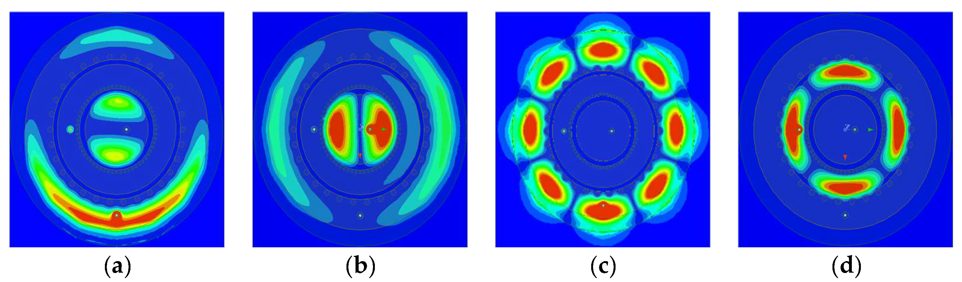
Figure 10.
Normalized radiation pattern at 5.93 GHz: (a) port 1; (b) port 3.
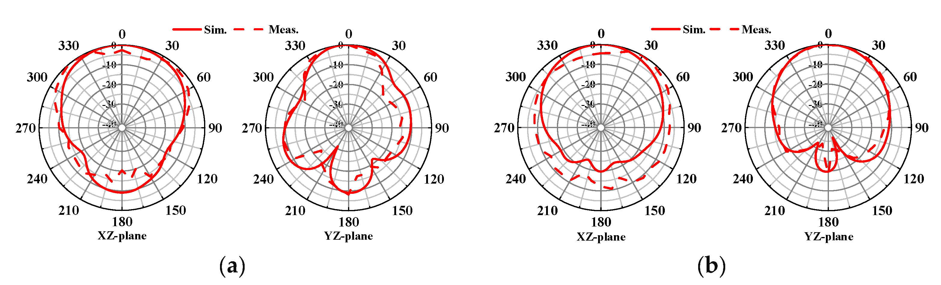
Figure 11.
Normalized radiation pattern at 7.92 GHz: (a) port 1; (b) port 2.
Disclaimer/Publisher’s Note: The statements, opinions and data contained in all publications are solely those of the individual author(s) and contributor(s) and not of MDPI and/or the editor(s). MDPI and/or the editor(s) disclaim responsibility for any injury to people or property resulting from any ideas, methods, instructions or products referred to in the content. |
© 2024 by the authors. Licensee MDPI, Basel, Switzerland. This article is an open access article distributed under the terms and conditions of the Creative Commons Attribution (CC BY) license (http://creativecommons.org/licenses/by/4.0/).
Copyright: This open access article is published under a Creative Commons CC BY 4.0 license, which permit the free download, distribution, and reuse, provided that the author and preprint are cited in any reuse.


