Submitted:
16 May 2024
Posted:
17 May 2024
You are already at the latest version
Abstract
With challenged early detection came the collapse of a school roof, initiating a storm of public mistrust and hundreds of schools under investigation in the United Kingdom. The culprit is a poorly understood material heavily used in the 1950s to mid-1990s, reinforced autoclaved aerated concrete (RAAC). As a lightweight material with excellent insulation, RAAC was mainly used in roof and floor panels in many parts of the world. However, RAAC has a comparatively weak compressive strength, poor reinforcement anchorage, and high permeability and susceptibility to creep. The uniqueness of RAAC properties is exacerbated by poor manufacturing, negligent construction and maintenance as well as structural deviations from original design intent. Current guidance lacks in specifying RAAC management strategies beyond recommendations for periodic surveying. This paper delivers a state-of-the-art review of the material properties and structural performance of RAAC to recommend improved measures characterised by non-destructive testing methods and digital asset management. The reviewed literature targets understanding the influence of variable environmental exposure conditions, reinforcement condition, operational loading variations, structural deficiencies, and ageing, to predict their effect on the mechanism of RAAC failure. The established risk factors of RAAC are examined to inform of feasible response strategies against specific issues encountered in affected RAAC structures such as inadequate bearings, compromised transverse reinforcement, and environmental conditions.
Keywords:
reinforced autoclaved aerated concrete
; digital asset management
; structural assessment
; retrofitting
1. Introduction
In the 1950s-1990s, reinforced autoclaved aerated concrete (RAAC) was heavily used in the UK as a lightweight construction material suitable for mass production in prefabricated roof, floor and wall components. In 2018, the collapse of a school roof made of RAAC panels initiated a blanket effect necessitating the inspection of the safety of all RAAC buildings in the UK. The safety concerns regarding RAAC performance originated in 1996 when the Building Research Establishment (BRE) noted that RAAC panels are reaching their end of service life with demonstrations of structural degradations. The BRE demonstrated this with in the publication of information paper IP 10/96 (1996) [1] showing the results of a series of tests on panels constructed in the years 1991 and 1995. These tests mainly involved material analysis, as well as cyclic loading and strength testing to understand the failure mechanism of panels with the typical reinforcement arrangements depicted in Figure 1.
In principle, the manufacture of RAAC imposes certain phenomena not common to standard concrete. For instance, the BRE cites the shadow effect as an attribute of RAAC panels. The shadow effect is defined as a feature specific to RAAC components developed during the AAC foaming process where voids are created near reinforcement bars; hence, it is believed that the shadow effect may be minimised by using smaller rebar diameters. However, a counter complication may arise whereby the larger AAC matrix predominantly absorbs the corrosion products and hence limits any visible cracking on the panel, contributing to the observed sudden shear collapse effect. The most common failure mechanisms are summarised in relation to their causes and possible control measures in Table 1.
An elaboration on the stage by which the most common degradation mechanisms appear is displayed in a Venn diagram in Figure 2. This aims to highlight the relevant RAAC development, i.e.: during design, manufacture, and construction. In establishing this information, newly built RAAC structures may be better equipped to control a predicted defect.
As the manufacturer of problematic RAAC panels is not certainly identifiably, current surveying trends may also infer correlations between different panels in relation to shared mechanisms hinting at shared manufacturing origins.
2. RAAC Properties
In principle, it is necessary to establish the differences between standard concrete and autoclaved aerated concrete (AAC) or aircrete to reflect the distinctive properties and structural behaviour. AAC is a lightweight siliceous material consisting of an aerated cellular structure produced from a reaction between calcareous and siliceous materials bonded by calcium silicate hydrates. The mixed slurry is poured into a steel mould before autoclave curing precedes binder setting for the RAAC to be ready for application. RAAC is therefore a lightweight porous material with excellent insulation capacity but suffers a low alkalinity and hence poor reinforcement bond in comparison with standard concrete [2-4]. Due to its high deformability afforded by the low density lending to reduced inertial forces, RAAC is proven to have excellent seismic capacity with its low stiffness producing high ductility, and subsequent ductile failure in exposure to dynamic loads [2]. A summary of the typical mechanical property ranges of RAAC panels is displayed in Table 2.
As an aerated mixture with high porosity, the moisture content of RAAC is highly critical whereby reduced moisture leads to improved mechanical properties [2], hence, the cellular microstructure is extremely vulnerable to degradation in humid or wet environments. The moisture content has been observed to affect the elastic modulus whereby reaching saturation can lead to a decrease of up to 20% in the elastic modulus of AAC [2]. Although AAC is highly water absorbent, in cases of poor rebar anchorage, penetrated water may circumvent the cementitious matrix and directly instigate corrosion. AAC also has a poor alkalinity and subsequent bond characteristics, therefore, the steel reinforcement is often coated with bitumen or cementitious latex to enhance its anchorage. However, according to the BRE, there have been cases of poor anchorage between the rebar and the coating material. In acknowledgment of poor bond characteristics, transverse anchorage reinforcement is welded to the longitudinal rebars at the end near the supports to control deflections arising from slippage. In the event of rebar corrosion, the typical outward expansion of concrete may not be observed in RAAC given the poor anchorage, making a collapse imminent with no signs of cracking or spalling. This phenomenon is especially prevalent where transverse reinforcement is lacking in RAAC panels. In the 1995 series of BRE tests on RAAC panels, it has been established that, by default, operational loads are carried by the reaction forces, and in the event of excessive deflections where rebar slippage may occur, the role of transverse rebars is mobilised to carry the ultimate load. In the second series of the BRE 1995 tests, this mechanism was depicted in Figure 3 where high deflections were concentrated in lacking transverse reinforcement at the end supports.
This mechanism explains the coupled importance of securing adequate bond strength in combination with transverse anchorage reinforcement in RAAC panels.
3. RAAC Approach
In Europe, the specific composition of the mixtures employed by individual producers is unique in used materials and manufacturing procedures [4]. Similarly, the exact material composition of the problematic RAAC panels is not entirely discernible. In response to the 2018 collapse incident, the Institution of Structural Engineers (IStructE) in the UK has produced a guidance detailing the identification, inspection, retrofitting, and management of RAAC structures [5]. This document serves as the rulebook for intervention measures to control the RAAC crisis. As will be detailed herein, the current RAAC intervention protocol may be best described as a reactive approach whereby risk conditions are assessed periodically in anticipation of poorly controlled deterioration.
3.1. Structural Assessment
According to the RAAC identification guidance produced by the Department for Education (DfE), the typical RAAC panel consists of distinguishing features such as being 600mm wide with lengths up to 6m and a chamfer to each end. Once RAAC is confirmed present, a structural assessment ensues to determine the risk category to which a given panel conforms. The risk categories are divided as high-risk necessitating immediate remediation, medium risk necessitating annual surveying, and low risk requiring periodic surveying every 5 years. The only condition that is considered an exception that may raise a panel’s risk level lies in whether water damage is suspected. Water ingress has been documented to greatly reduce the mechanical properties of AAC while contributing to corrosion and debonding, hence the classification of water damage as a high-risk event. In most applications, RAAC panels are laid flat in roofs which dramatically increases the probability of assuming water exposure and hence all associated pernicious effects. Nonetheless, the subsequent recommendation for immediate remediation hints at the need to classify water related degradation accurately to ascertain that it has occurred to a quantifiable degree.
The main issues encountered in RAAC panels may be divided into two categories: panel defects, and reinforcement defects. Panel defects are mostly screened with NDT methods targeting issues such as cracking, spalling, waterproof membrane damage, and high deflections. Reinforcement defects are assessed with a combination of NDT methods and destructive testing to confirm the availability of transverse reinforcement, and adequate end bearing conditions. A summary of the currently identified risk factors targeted in inspections is displayed in Table 3.
According to the IStructE guidance, the failure mode associated with missing transverse reinforcement is presently a subject of academic research. In an experiment conducted to study the post-elastic response of aircrete and explore parameters for estimating deflection [4]. The failure at ultimate load was reported to occur primarily at the side of deficient anchorage bars. In the 1995 series of laboratory studies conducted by the BRE, the deflection observed in relation to maximum load sustained by a given RAAC panel takes the shape of a beam nonuniformly loaded at one end. For simplicity, the failure mode may be described with first principles where the deflection is concentrated in the edge due to lacks in adequate bearing length and transverse reinforcement. This may be an important observation in relation to the assessment stage where a RAAC panel may be sagging on one end to produce a gap with the adjacent panel. Although this deflection (greater than 20mm) is considered a critical risk, it is not clearly attributed to any given phenomenon. In the BRE tests series, near support deflections were attributed to the location and condition of transverse rebar. Given the insight derivable from such studies, it is imperative that other independent case studies are reviewed to identify possibly overlooked defects as shown in Table 4.
3.1.1. Surveying
The fragile nature of RAAC entails a non-intrusive inspection survey whereby the previously outlined concerns can be assessed safely. By default, NDT takes precedence in screening for lacking transverse reinforcement or in evaluating deflection in RAAC panels. The reinforcement condition is tested for availability of transverse reinforcement by utilising covermeters and radar scanning to ensure longitudinal rebar continuity over end bearings. However, there are limitations associated with the reliability of these methods with variables such as panel thickness interfering with scanning. Moreover, as seen in Table 2, in a case study of RAAC roof panels built in the early 1970s, visible longitudinal bars were observed near supports which led to the incorrect assumption that more bars existed sufficiently throughout the panel’s span [4]. This is an especially crucial observation given that the IStructE guidelines mainly concern the inspection of end bearings and subsequent transverse reinforcement without sufficient regard to midspan rebar continuity. As such, drilling is also used to ascertain bearing length and reinforcement conditions. Naturally, such intrusive surveys may compromise the fragile structural integrity of RAAC panels. Additionally, intrusive surveys increase the risk of encountering the well-documented presence of asbestos within RAAC panels or surface coverings [6].
In assessing deflection, the IStuctE guidance recommends that at least 10% of panels are selected strategically as representative samples according to their location and condition. A laser level is utilised to record panel deflection values to either recommend remediation or serve as baseline measurements for future investigations. A summary of the surveying process is demonstrated in Figure 4. Evidently, this process is cost, time, and labour heavy with considerable allowance for human error.
In surveying for signs of water damage, cracks are the main target of observations. However, there is no specific method adopted for assessing water damage. In the 1981 case study of roof panels, the effects of water damage may be further explored to inform of possible signs to target in inspection. At first, panel deflection was recorded at supports and assumed to be a byproduct of water damage caused by the roof membrane stretching at supports. It was then inferred that thermal stresses and water evaporation cycles may have contributed to the excessive deflection. As such, it may be reasonable to especially suspect water damage as a byproduct of deflections occurring at the edges of panel spans owing to the effect of stressed roof membranes. Similarly, the water ponding has been found to induce a creep effect on aircrete slabs [4]. In essence, the current procedures of structural assessment and retrofitting of RAAC structures utilises exaggerated remediation measures where water damage is suspected. The manual inspection methods are challenged by the varied properties of RAAC and its differential deterioration mechanisms depending on factors such as method of manufacture, environment, geometry, and age. In exacerbation, the poor maintenance of RAAC may be a direct consequence of lacking integrated survey data.
3.2.. Management
The challenged management of RAAC structures is a testament to the importance of the digitalisation of the construction sector. The role of digitalisation in the survey and management of RAAC has been severely lacking as evident by the emphasis on manual inspection methods in the latest guidance [5]. In a recent attempt at digitising RAAC inspections, researchers at the University of Loughborough have developed a digital tool capable of identifying the presence and nature of cracks in images of RAAC panels [7]. This method is reliant on a systematic approach of photographing the RAAC panels in order to efficiently track the development of identified cracks, hence increasing the predictability of RAAC behaviour for improved management. Nonetheless, this digital tool is not advised to be used in replacement of any manual inspection methods due to the wide variability and perceived novelty of RAAC conditions. The contribution of this digital tool remains relatively minimal in relation to the properties of RAAC and its ability to degrade significantly without presenting any noticeable cracking. This has been demonstrated in the BRE study of RAAC panels constructed in 1995 where no significant cracking was observed under any load or environmental exposure testing [8]. In essence, the poorly understood properties of RAAC challenges the effectiveness of integrating digital solutions. In the IStuctE guidance [5], it is suggested that a monitoring plan is strategised to manage RAAC conditions.
3.2.1. Residual Risk
The current risk categorisation system may be overly simplifying the complexity of the material and composite behaviour, especially since it has been observed that panels do not act uniformly as one structural entity. In addressing this, IStructE guideline advises that while all panels must be visually assessed, no less than 10% of total panels are to be assessed for deflection. However, this attempt at a holistic understanding of may remain insufficient to determine overall safety. In respect to the challenging inspection and classification of RAAC panel safety, there may be residual risk in a falsely classified panel. According to the latest published data by the DfE, there is a total of 214 schools with confirmed RAAC [9]. The DfE specifies 18 classrooms per school in average [10], with the average classroom size being 70m2. In a total of 214 schools, this translates to approximately 215,712 RAAC panels currently present in UK schools with potential for spontaneous collapse. This risk may be higher in larger buildings where occupation is perennial unlike schools, hence adding to the likelihood and magnitude of risks associated with RAAC failures.
4. Digitalised RAAC Approach
In current RAAC surveying processes, a major gap exists in the effective utilisation of appropriate NDT methods. As a porous material with a non-solid matrix, RAAC is not typically inspected with NDT methods standard to traditional concrete. This is the gap presently filled with invasive drilling and coring of RAAC panels for reinforcement condition testing and material analysis. In acknowledgement of risks associated with inspection and management limitations, the DfE has recently approved funding for the rebuilding and repurposing of RAAC affected buildings as a standard response instead of opting for remedial maintenance efforts [11]. Given the large economic commitment, it may be argued that other approaches aimed at long-term understanding of RAAC performance pose as an equally worthwhile investment.
At present, technology centres and independent R&D companies are in the process of revolutionising the RAAC crisis management. Namely, the Manufacturing Technology Centre (MTC) is pioneering the use of NDT methods such as imaging technology utilising x-ray backscatter (XBT) and x-ray computed tomography (XCT) in the inspection of panels for reinforcement condition [12]. Meanwhile, a software development approach pioneered by Everyware and funded by the Engineering and Physical Sciences Research Council in the UK relies on DAM concepts utilising sensors equipped with Internet of Things (IoT) capacity [13]. This may be especially useful when utilised to target specific deterioration factors. For instance, a IoT enabled hygrometer can inform key personnel of high or fluctuating humidity environments to circumvent its negative effects on the mechanical properties of RAAC structures [4].
The challenge in current efforts is in the segregation of research whereby NDT methods are developed to be prototyped separately from the DAM schemes. An improved framework characterised by NDT in the inspection and surveying may entail using imaging technology (i.e.: XBT and XCT) to capture a panel’s reinforcement without the need for destructive drilling whereby covermeters or radar scanning remain inconclusive. The field application of XCT as an NDT method for porous concrete has proven successful in evaluating the degree of clogging in porous concrete [14]. Where no high-risk conditions are established, risk mitigations may be mobilised before implementing a monitoring strategy for medium and low risk RAAC structures. The workflow of this monitoring scheme is demonstrated in Figure 5 whereby an autonomous system is looped to produce a holistic understanding of a RAAC structure’s condition.
In the event of high-risk conditions, the panel may then be repaired or replaced as adopted in current practices. The replaced panel may be transferred for additional testing whereby other standardised NDT methods such as ultrasonic pulse velocity (UPV), may be studied for validity of use in surveying existing RAAC panels. In a study exploring the effects of reinforcement on UPV readings, it is established that readings can be made reliable in low-density concretes by utilising a correction factor accounting for the rebar effect [15]. Other interesting NDT methods to explore include infrared thermography aimed at assessing moisture or thermal anomalies within RAAC panels. This can significantly impact the current risk category classification system whereby water damage may be ascertained, eliminating unnecessary remediation. This approach will also contribute to the continuing understanding of enhancing the lifecycle of existing RAAC panels, eliminating unsustainably defaulting to renovations.
There are immediate and long-term advantages in utilising an autonomous monitoring scheme. The current cycle of periodic allocation of time, cost, and labour resources for manual inspection is partially encouraged by the DfE funding for a blanket solution of complete renovation. In adopting a manufacture-led approach, this cycle may be replaced with consistent inspection and specific remediation targets. In the end of service life of a panel whereby replacement has been deemed necessary, the established knowledge of RAAC behaviour through monitoring can also facilitate greater reuse potential. It has been documented that 10% of AAC can be used as partial replacement of fine aggregate to reduce the density and enhance the compressive strength of concrete [16]. However, recycle and reuse of AAC is a scarce topic in existing literature.
4.1. Remediation
Given that RAAC has been widely misused in the 1950s-1990s, the newly established standards for RAAC BS EN 12602 and reinforcement optimisation to BS EN 990 promote best practice for reliable design and manufacture to realise the material’s structural potential. This may support remediation efforts whereby optimised RAAC panels may be prototyped for retrofit purposes capable of addressing the risk conditions reliably identified in monitor schemes. For instance, in roof construction of RAAC panels, builders apply the bituminous roof membranes and painting of soffit immediately after manufacture, hence trapping the moisture in panel and affecting the elastic modulus [4]. In future construction, improved RAAC lifecycles can be attained by accommodating technology such as water barrier impregnation produced specifically for a porous concrete matrix [17]. In renovation efforts, MTC recommends the utilisation of technology such as products platforms whereby common elements may be used across newly built RAAC structure to enable the use of a renovation kit of parts in future defect remediation [12]. In addition, it may be worth exploring the potential of embedding sensors in newly built RAAC panels to enable a quantifiable comparison between existing and new RAAC structures, hence further bolstering the agenda of DAM towards informed intervention measures.
5. Conclusion and Future Directions
The early construction practises of RAAC structures have witnessed engineering and manufacturing negligence which has led to exceptionally compromised lifecycle performances. This highlights the timely importance and criticality of careful inspection and retrofitting procedures. In contrast to the current guidance of RAAC surveying where invasive inspections are suggested, this paper has proposed a novel framework inspired by the known properties and common defects of RAAC panels. This framework is primarily a preventative approach transforming the reactive approach of current guidance. It is characterised by its reliance on digitisation and automation of surveying practises ascribing to DAM processes. In support of this, a literature review was conducted to observe existing case studies to address possibly overlooked RAAC defects A quantitative evaluation of the feasibility of this approach remains necessary in order to propose a deployable prototype that monitors for specific degradation mechanisms and environmental conditions for wider adoption.
Future research may aim to fulfil the wide scarcity of literature on RAAC properties and behaviour as a structural material. The utilisation of NDT methods in porous concrete structures is a challenge due to the peculiarity of a majorly non-solid matrix inhibiting accuracy as found in standard concrete. As such, it is recommended that any replaced RAAC structures is utilised for testing in controlled conditions to establish the reliability of NDT methods for future field surveying.
Author Contributions
Conceptualization, D.A. and L.D.S..; methodology, D.A.; validation, D.A. and L.D.S.; formal analysis, D.A.; investigation, D.A.; resources, D.A. and L.D.S.; data curation, D.A. and L.D.S.; writing—original draft preparation, D.A.; writing—review and editing, D.A., and L.D.S.; visualization, D.A.; supervision, L.D.S.; project administration, L.D.S.; funding acquisition, L.D.S. All authors have read and agreed to the published version of the manuscript.
Funding
This research received no external funding.
Data Availability Statement
Not applicable.
Conflicts of Interest
The authors declare no conflicts of interest.
References
- www.thenbs.com. (1996). Information Paper 10/96 Reinforced autoclaved aerated concrete planks designed before 1980, BRE - Publication Index | NBS. [online] Available at: https://www.thenbs.com/PublicationIndex/documents/details?Pub=BRE&DocID=98696 [Accessed 20 Mar. 2024].
- www.thenbs.com. (2002). Report BR 445 Reinforced autoclaved aerated concrete panels: review of behaviour and developments in assessment and design, BRE - Publication Index | NBS. [online] Available at: https://www.thenbs.com/PublicationIndex/documents/details?Pub=BRE&DocID=260492.
- Tanner, J., Varela, J., Brightman, M., Cancino, U., Argudo, J. and Klingner, R. (2016). Seismic performance and design of autoclaved aerated concrete (aac) structural systems. In: 13th World Conference on Earthquake Engineering. [online] Vancouver, B.C., Canada. Available at: https://www.iitk.ac.in/nicee/wcee/article/13_541.pdf.
- Campbell, P. (2001). Learning from construction failures: applied forensic engineering. New York: Wiley, pp.206–226.
- Istructe.org. (2023). Reinforced Autoclaved Aerated Concrete (RAAC) Investigation and Assessment – Further Guidance - The Institution of Structural Engineers. [online] Available at: https://www.istructe.org/resources/guidance/reinforced-autoclaved-aerated-concrete-(raac)-inve/.
- Health and Safety Executive HSE Books. (n.d.). Available at: https://www.hse.gov.uk/pubns/priced/hsg264.pdf.
- Loughborough University. (2023). Loughborough researchers behind ‘first of its kind’ AI tool that aims to cut time needed to survey and maintain RAAC. [online] Available at: https://www.lboro.ac.uk/news-events/news/2023/october/new-ai-tool-to-survey-raac.
- Matthews, S., Narayanan, N. and Goodier, A. (2002). IP 7/02 Reinforced autoclaved aerated concrete panels: test results, assessment and design, BRE - Publication Index | NBS. [online] www.thenbs.com. Available at: https://www.thenbs.com/PublicationIndex/documents/details?Pub=BRE&DocID=257354.
- Department for Education (2023). UK Government Web Archive. [online] webarchive.nationalarchives.gov.uk. Available at: https://webarchive.nationalarchives.gov.uk/ukgwa/20231030194200/https://www.gov.uk/government/publications/reinforced-autoclaved-aerated-concrete-raac-management-information.
- Area guidelines for mainstream schools Building Bulletin 103. (2014). Available at: https://assets.publishing.service.gov.uk/media/5f23ec238fa8f57acac33720/BB103_Area_Guidelines_for_Mainstream_Schools.pdf.
- Department for Education (2024). Government confirms plans to permanently remove RAAC from all schools and colleges in England. [online] GOV.UK. Available at: https://www.gov.uk/government/news/government-confirms-plans-to-permanently-remove-raac-from-all-schools-and-colleges-in-england.
- Written evidence submitted by the Manufacturing Technology Centre (MTC). (2022). Available at: https://committees.parliament.uk/writtenevidence/122316/pdf/.
- C-DICE. (2024). Industrial Secondment: Reinforced Autoclaved Aerated Concrete (RAAC) monitoring. [online] Available at: https://www.cdice.ac.uk/news/everyware.
- Manahiloh, K.N., Muhunthan, B., Kayhanian, M. and Gebremariam, S.Y. (2012). X-Ray Computed Tomography and Nondestructive Evaluation of Clogging in Porous Concrete Field Samples. Journal of Materials in Civil Engineering, 24(8), pp.1103–1109. [CrossRef]
- Fodil, N., Chemrouk, M. and Ammar, A. (2019). The influence of steel reinforcement on ultrasonic pulse velocity measurements in concrete of different strength ranges. IOP Conference Series: Materials Science and Engineering, 603, p.022049. [CrossRef]
- Alik, A. and Majid, M. (2023). View of Physical and Mechanical Properties of Autoclaved Aerated Concrete (AAC) as Partial Fine Aggregate in Concrete. [online] publisher.uthm.edu.my. Available at: https://publisher.uthm.edu.my/periodicals/index.php/rtcebe/article/view/5745/3487.
- Holman, H. (2023). Mitigation through impregnation – solving the ongoing RAAC issue. [online] Nano-Care. Available at: https://www.nano-care.co.uk/2023/09/mitigation-through-impregnation-solving-the-ongoing-raac-issue/.
Figure 1.
Typical profile of RAAC panel [1].
Figure 1.
Typical profile of RAAC panel [1].
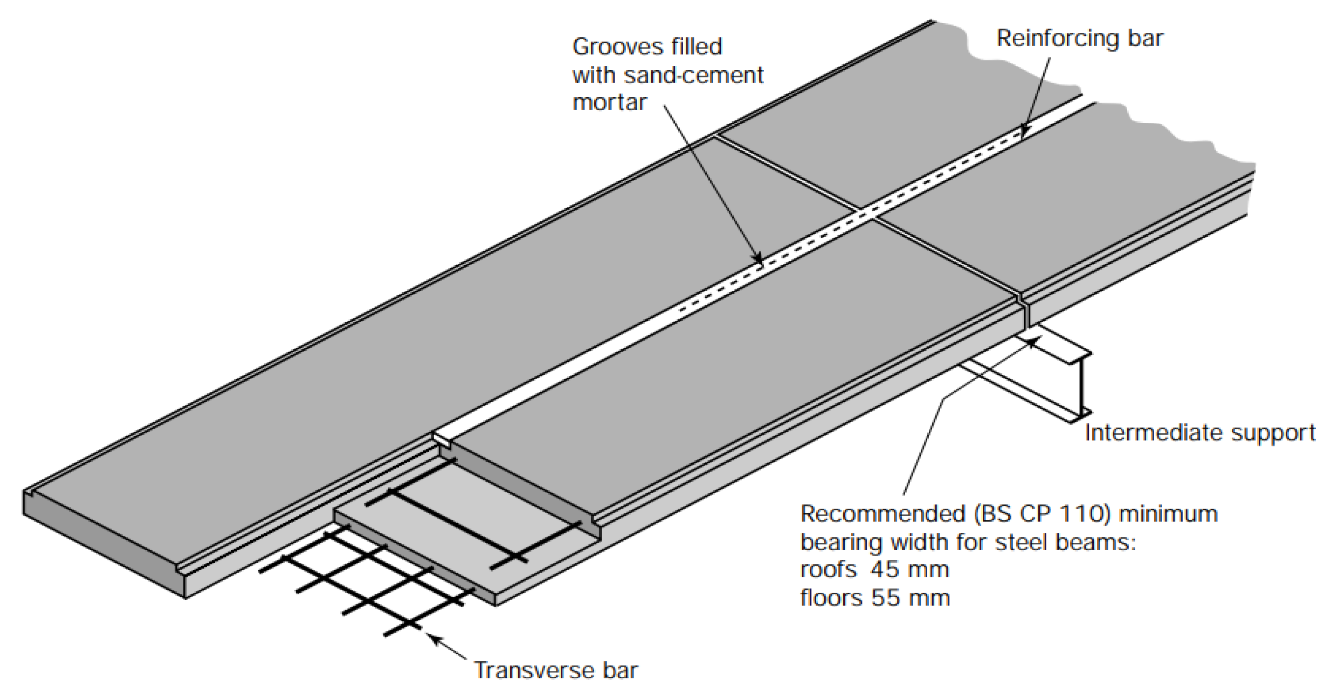
Figure 2.
Venn diagram of stages in which common RAAC defects originate.
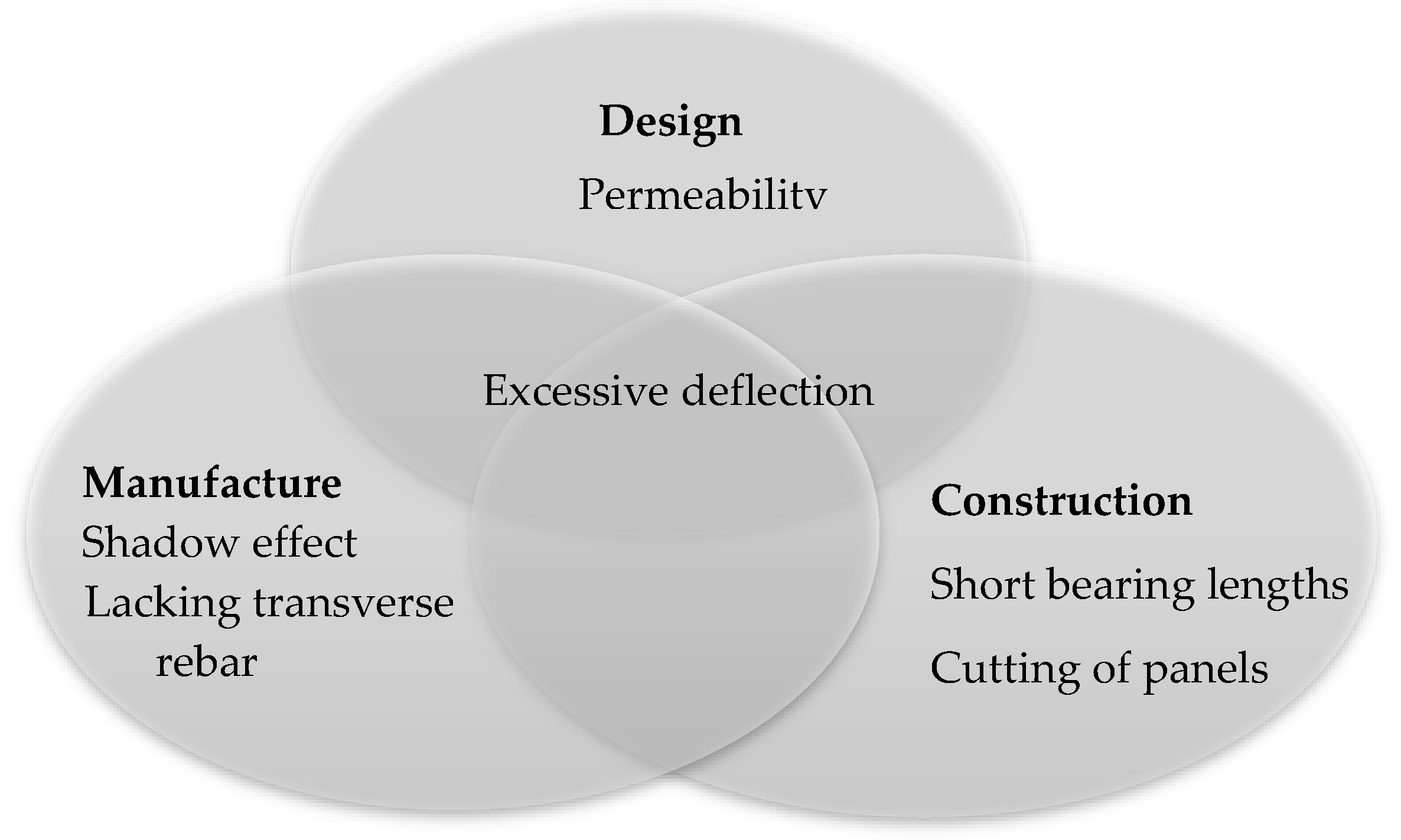
Figure 3.
Deflection of RAAC panels at ultimate load in second series of 1995 tests [2].
Figure 3.
Deflection of RAAC panels at ultimate load in second series of 1995 tests [2].
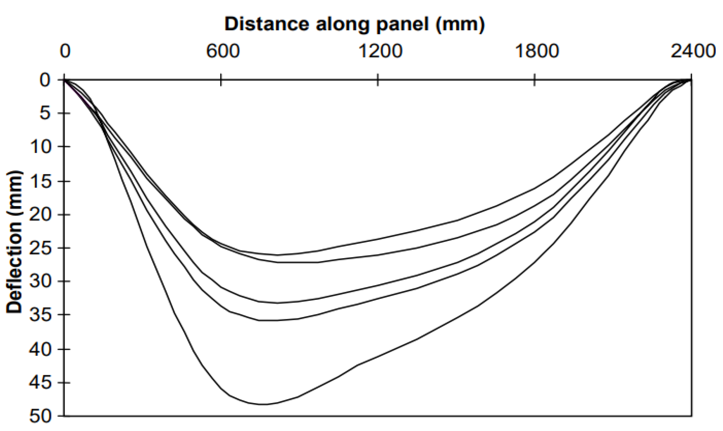
Figure 4.
Current RAAC inspection, remediation, and management practices.
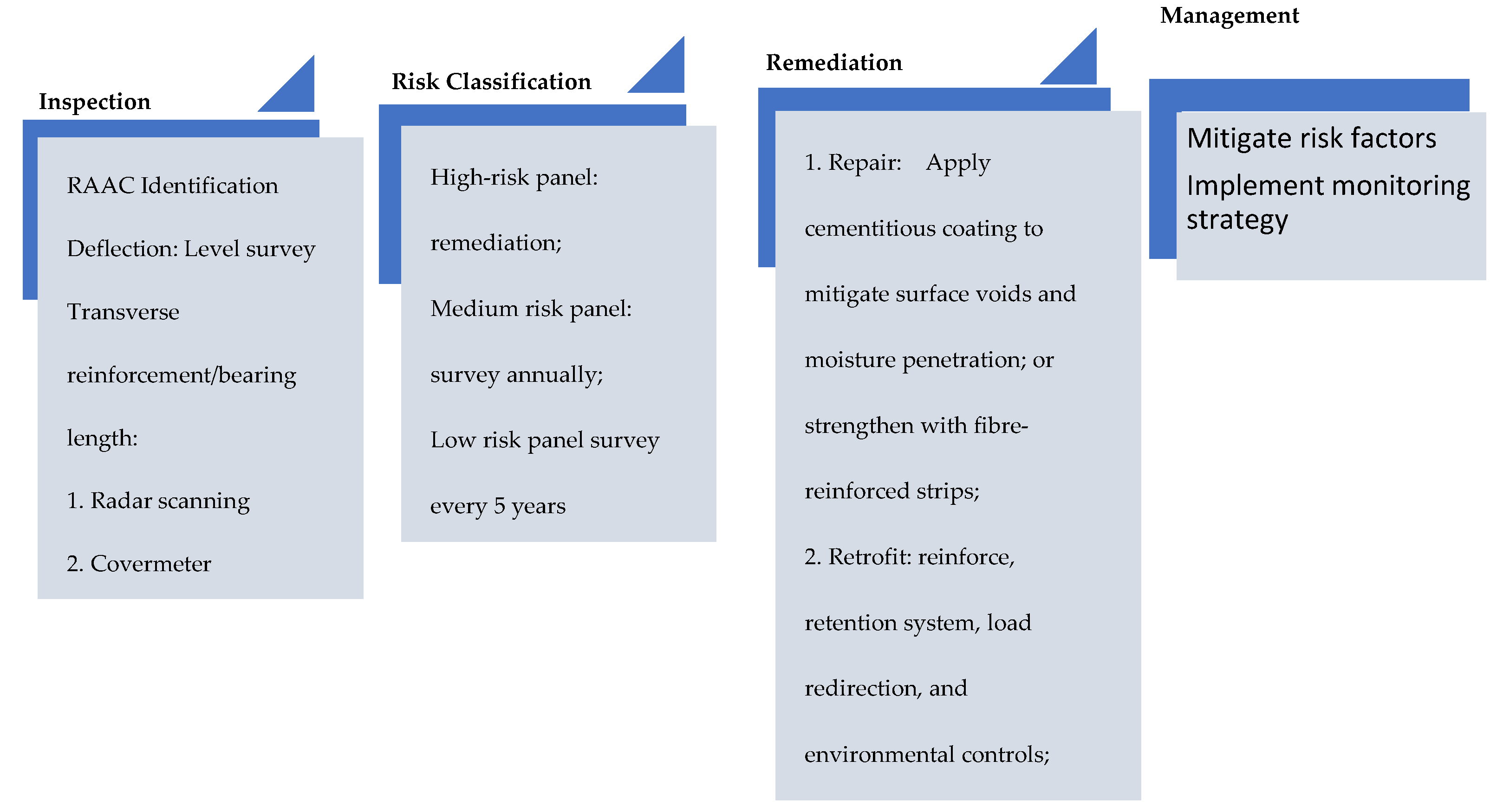
Figure 5.
Automated RAAC inspection and management process.
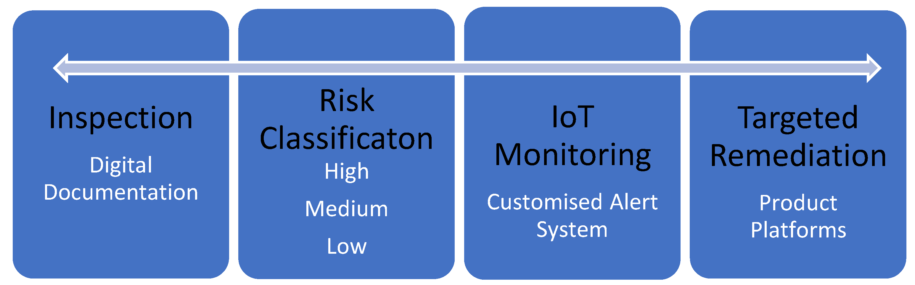

Table 1.
Common failure mechanisms associated with RAAC panels [2].
Table 1.
Common failure mechanisms associated with RAAC panels [2].
| Degradation | Cause | Control |
|---|---|---|
| Shadow effect | AAC foaming process | Smaller diameter rebar |
| Rebar corrosion | High moisture content Rebar coating debonding |
Protective waterproof membrane |
| Excessive deflection | Poor reinforcement anchorage Thermal cycling Moisture movement |
Ensure sufficient bearing length |
Table 2.
Typical value ranges of mechanical properties of RAAC panels.
| Property | Range | Reference |
|---|---|---|
| Compressive strength (N/mm2) | 2 – 5 | [5] |
| Flexural strength (N/mm2) | 0.55 – 1.54 | [4] |
| Elastic modulus (kN/mm2) | 0.50 – 3.30 | [2] |
Table 3.
IStructE guidance on high-risk conditions under water damage [5].
Table 3.
IStructE guidance on high-risk conditions under water damage [5].
| Risk Condition | Observation |
|---|---|
| Lack of transverse reinforcement | Peculiar panel geometry indicating cutting or modification |
| Hangers supporting panels | |
| Bearing length less than 75mm | |
| Deflection | Adjacent panels gap greater than 20mm |
| High span/depth deflections | |
| Panel cracking or spalling | Major cracking or spalling |
| Minor cracking or spalling within 500mm of supports |
Table 4.
UK case studies and experiments on RAAC structures [4].
Table 4.
UK case studies and experiments on RAAC structures [4].
| Study | Observation |
|---|---|
| 1970s steel frame portal shed with RAAC roof panels | Inadequate tension reinforcement with diameter less than 6mm |
| Visible perimeter longitudinal bars | |
| High span to depth ratio (S/D = 26) | |
| 1976 residential building with RAAC panels | Failure of longitudinal joints between slabs |
| Large variation in cracking and deflection despite adequate performance tests of AAC properties | |
| Irreversible moisture movement resulting in reduced elastic modulus and shorter slab | |
| 1981 complex with RAAC roof panels | Insufficient cross-bars |
| High moisture content (greater than 7%) | |
| Corrosion of unprotected reinforcement leading to rebar diameter reduction | |
| High span to depth ratio (S/D = 30) leading to excessive deflection | |
| Roof membrane stretching at supports and allowing water ponding | |
| Damp roof soffits indicative of water damage | |
| 1991 & 1995 BRE experiments | Deflection and transverse cracking at soffit taken as evidence of long-term slippage between AAC and rebar as well as localised corrosion |
Disclaimer/Publisher’s Note: The statements, opinions and data contained in all publications are solely those of the individual author(s) and contributor(s) and not of MDPI and/or the editor(s). MDPI and/or the editor(s) disclaim responsibility for any injury to people or property resulting from any ideas, methods, instructions or products referred to in the content. |
© 2024 by the authors. Licensee MDPI, Basel, Switzerland. This article is an open access article distributed under the terms and conditions of the Creative Commons Attribution (CC BY) license (http://creativecommons.org/licenses/by/4.0/).
Copyright: This open access article is published under a Creative Commons CC BY 4.0 license, which permit the free download, distribution, and reuse, provided that the author and preprint are cited in any reuse.


