
Submitted:
15 May 2024
Posted:
16 May 2024
You are already at the latest version
Abstract
Although the spanwise periodicity within the gap between two tandem circular cylinders has been observed by some researchers, there is a lack of systematic study on the properties of this pe-riodicity. For the spanwise periodicity within the gap, this study aims to ascertain its characteris-tics, its influences on the flow field, and its variation trend with increasing spacing ratio. By nu-merically simulating the flow around two tandem circular cylinders with a diameter ratio of d/D=0.6 and seventeen spacing ratios (L/D=1.00~6.00) at Re=3900, this study shows four flow re-gimes: Reattachment Flow (L/D=1.00~3.15), Bi-stable Flow (L/D=3.24), Intermittent Lock-in Co-shedding (L/D= 3.30~3.50) and Subharmonic Lock-in Co-shedding (L/D=4.00~6.00). Further, de-pending on the spanwise periodicity length of the time-averaged flow structures (i.e. Pz) within the gap, Reattachment Flow is, for the first time, subdivided into three new sub-flow regimes: Small-scale Periodic Reattachment (L/D=1.00~1.50, Pz/D=(0, 4]), Large-scale Periodic Reattachment (L/D=2.00~2.25, Pz/D>4) and Non-periodic Reattachment (L/D=2.50~3.15, no spanwise periodicity). The formation mechanisms are elaborated by analyzing the combined effect of both the L/D value and the spanwise-averaged time-averaged reattachment angle of the downstream cylinder. Moreover, this study proves that the newly-defined Small-scale Periodic Reattachment and Large-scale Periodic Reattachment are responsible for the pronounced asymmetry of the flow along the transverse direction within the gap. In addition, detailed flow properties and statistical pa-rameters are provided for each flow regime, such as velocity, vorticity, force coefficient, separa-tion/reattachment angle, Strouhal number and Q-criterion.
Keywords:
Spanwise periodicity
; Small-scale periodic reattachment
; Large-scale periodic reattachment
; Non-periodic reattachment
; Bi-stable flow
; Co-shedding flow
1. Introduction
Despite the simplicity of the geometry, the flow around cylindrical structures is of fundamental significance and involves complex flow mechanisms, including vortex shedding/ impingement/ interaction, shear layer separation/reattachment, transition from steady to unsteady state, transition from two-dimensional (2D) to three-dimensional (3D) state, fluid-structure interaction and flow-induced noise/vibration [1,2,3,4,5]. Abundant studies have been conducted to elucidate the flow around circular or square cylinders, due to their extensive engineering applications [6,7,8,9,10]. Especially, two tandem circular cylinders have attracted considerable attention in recent decades [11,12,13,14,15].
The flow around two tandem circular cylinders is influenced by the Reynolds number (Re), the spacing ratio (L/D, where L is the center-to-center distance between two cylinders and D is the cylinder diameter), the turbulence intensity of the approaching flow, the boundary condition, the blockage ratio and the cylinder aspect ratio [16,17,18]. No consensus has been reached about the classification of flow patterns, being ascribed to diverse influencing factors and different classification standards. On one hand, experimental studies categorized flow pattern with the aid of various flow visualization techniques, such as surface oil-flow visualization, soap film visualization, laser-induced fluorescence and smoke-wire flow visualization [19,20]. On the other hand, numerical studies defined diverse flow regimes by various physical quantities, such as vorticity, velocity, Q-criterion, λ2-criterion, force coefficient, Strouhal number and streamlines [21,22,23].
The flow around two tandem circular cylinders with equal diameters is classified into Single Body Flow (i.e. proximity flow, extended-body flow or overshoot flow), Reattachment Flow, Bi-stable Flow and Co-shedding Flow (i.e. binary-vortex flow) [24,25]. Particularly, Zdravkovich [26] found that, when 1.2≤L/D≤4.0, the shear layers might reattach on the downstream cylinder in three different manners, namely alternate reattachment, quasi-steady reattachment and intermittent reattachment. Alam et al. [27] and Alam [28] provided four types of reattachment flow, namely the reverse-flow reattachment, the front-side reattachment, the front reattachment and the rear-side reattachment. Zhou and Alam [12] pointed out that about 50% of previous investigations were conducted at Re=1×10⁴~ 3.5×10⁵, but approximate 20% at Re=1×10³~1×10⁴ and only 3% at Re>3.5×10⁵. Rastan and Alam [29] indicated that Single Body Flow (SB) was absent for Re≥2×10⁴, a hysteresis zone (HS) was observed within Re=50~500, and Bi-Stable Flow (BS) was acquired at Re≥1000, being distinguished by spontaneous intermittent switches between the alternate reattachment flow (AR) and the co-shedding flow (CS) at a fixed Re and L/D.
Only few investigations were devoted to clarifying the flow around two different-sized tandem circular cylinders. Alam and Zhou [30] analyzed the wake of two tandem circular cylinders with d/D=0.24~1.0 and L’/d=5.5 at Re=2.72×10⁴, where d was the upstream-cylinder (UC) diameter, D was the downstream-cylinder (DC) diameter, and L’ was the distance from the UC center to the forward stagnation point of the DC. Co-shedding Flow was subdivided into Intermittent Lock-in (d/D≥0.4) and No Lock-in (d/D=0.24). Zafar and Alam [31] found that, when 0.3≤d/D≤1.0 (Co-shedding Flow), the DC wake featured a primary vortex street followed by a secondary vortex street, having a frequency 1.73 times smaller than the primary frequency. Shan [32] classified Co-shedding Flow into prime vortex shedding (PVS) mode, two-layer vortex shedding (TVS) mode and secondary vortex shedding (SVS) mode. Wang et al. [33] categorized Co-shedding Flow into Lock-in (L’/d≥3.0 at d/D=1.0; L’/d≥3.5 at d/D=0.8), Subharmonic Lock-in (L’/d≥3.5 at d/D=0.6) and No Lock-in (L’/d≥4.5 at d/D=0.4; L’/d≥7.0 at d/D=0.2). Alam et al. [34] investigated two tandem cylinders with d/D=0.25~1.0 and L’/d=5.5~20 at Re=0.8×10⁴~2.42×10⁴. Five flow regimes were identified, namely Reattachment Flow, Lock-in, Intermittent Lock-in, Subharmonic Lock-in and No Lock-in. Mahir and Altaç [35] observed four flow patterns, including over-shoot, symmetric-reattachment, front-side reattachment and co-shedding, for d/D=0.3~2.0 and G/D= 0.5~4.0 at Re=100~200, where G was the gap distance. Gao et al. [36] displayed that, for d/D=2/3 and L/D=1.8~3.8 at Re=200, the flow was characterized by a bi-stability phenomenon, and co-shedding might occur depending on the initial perturbation.
Special attention should be paid to the spanwise periodicity of the flow field between two tandem circular cylinders. Carmo and Meneghini [22] revealed that, for d/D=1.0 and L/D=1.5~5.0 at Re=270, the spanwise periodicity was very evident for both the gap region and the DC downstream with respect to the instantaneous x-vorticity or z-vorticity iso-surfaces. Papaioannou et al. [37] disclosed that the case of d/D=1.0 and L/D=2.0 at Re=500 belonged to Reattachment Flow, and obvious spanwise periodicity was observed for both the gap region and the DC downstream in terms of the instantaneous vorticity field. Hu et al. [38] showed that, for d/D=1 and L/D=1.5~2.5 at Re=2.8×10⁵~ 7.0×10⁵, whether for Reattachment Flow (L/D=1.5) or for Co-shedding Flow (L/D=2.5), both the instantaneous velocity contours at different Z planes and the instantaneous vorticity contours in the Y=0 plane demonstrated the evident spanwise periodicity. Deng et al. [39] examined the spatial evolution of vortices in the wake of two tandem circular cylinders with d/D=1 and L/D=1.5~8.0 at Re=220, and verified the existence of the spanwise periodicity in terms of both instantaneous streamlines and instantaneous vorticity contours.
For the flow around two tandem circular cylinders with a diameter ratio of d/D=0.6 at Re=3900, this study is dedicated to systematically analyzing the spanwise periodicity within the gap (including its own characteristics, its influences on the flow field and its variation trend with increasing spacing ratio), and further defining different flow regimes. In order to acquire the precise flow field, the large eddy simulation (LES) technique is employed to deal with the turbulence, and the local dynamic k-equation subgrid-scale (LDKSGS) model is utilized to obtain the subgrid-scale eddy viscosity [40,41]. In this study, seventeen spacing ratios (i.e. L/D=1.00, 1.10, 1.15, 1.20, 1.25, 1.50, 2.00, 2.25, 2.50, 3.00, 3.15, 3.24, 3.30, 3.50, 4.00, 5.00 and 6.00) are considered in an effort to adequately capture various flow regimes and detailedly illustrate the transition process among them. Flow properties and statistical parameters are presented for each flow regime, such as velocity/vorticity contours, force coefficient, reattachment/separation angle, Strouhal number, wavelet scalogram, Q-criterion iso-surface and the spanwise periodicity length.
2. Materials and Methods
2.1. Governing Equations
This study solves the turbulence by using the LES technique. By assuming the commute between the filtering operation and the differentiation operation, the filtered incompressible continuity and momentum equations can be derived as [40]:
where (i=1, 2 and 3) are the filtered velocity components in the streamwise (X axis), transverse (Y axis) and spanwise (Z axis) directions, respectively, represents the filtered kinematic pressure (i.e. pressure divided by fluid density), ν denotes the Newtonian-fluid kinematic viscosity, t symbolizes the time, =-is the subgrid-scale (SGS) stress tensor, and the overbar signifies the space filtering operation. Besides the geometrical parameters (e.g. d/D, L/D and H/D), the flow around two tandem circular cylinders is only governed by the dimensionless Reynolds number (Re=D/ν, where is the time-averaged velocity of the approaching flow and D is the cylinder diameter). In other words, by controlling the value of Re, the present numerical results are suitable for all Newtonian fluids, such as water and low-velocity gas. In this study, the large-scale eddies are directly resolved with the aid of Equation 1 and Equation 2, while the small-scale eddies are incorporated into the term and are dealt with the SGS turbulence model (employing the Boussinesq hypothesis), as described by Equation 3 and Equation 4.
where is the resolved strain rate tensor and is the SGS eddy viscosity, which is calculated through the LDKSGS model in this study.
where is the grid filter size, and the SGS kinetic energy is obtained by solving its transport equation. The simple top-hat filter method is used here, and the maxDeltaRatio coefficient is set as 1.1. For the two model constants, the officially recommended values of Ck=0.094 and Cε=1.048 are utilized in this study [41].
2.2. Boundary Conditions
Four kinds of boundary conditions are involved in this study:
(1) Inlet: A fixed uniform velocity is prescribed (=1 m/s, ==0 m/s), and the zero-gradient condition is applied for the pressure field (=0). The turbulent intensity (I) is set as 0.5%, and hence the turbulent kinetic energy (k) is fixed as 3.75×10⁻⁵ m2/s2.
(2) Outlet: For the velocity field, the convective outflow boundary condition is adopted [42,43]: , where denotes all the three velocity components, and uc is the convective velocity at the outlet. For the pressure field, the homogeneous Dirichlet condition (=0 Pa) is exerted at the outlet. For the turbulent kinetic energy, the zero-gradient condition (=0) is used.
(3) Cylinder surfaces: No-slip impermeable boundary condition is prescribed for the velocity field (===0 m/s), the zero-gradient condition is employed for the pressure field (=0), and the kLowReWallFunction is adopted for the turbulent kinetic energy.
(4) Top, bottom, front and back boundaries: The symmetric boundary condition is utilized, which means that the normal gradient of all variables is equal to zero (i.e. =====0).
2.3. Numerical Scheme
The Pressure Implicit with Splitting of Operators (PISO) algorithm is employed to deal with the pressure-velocity decoupling, the MUSCL scheme is chosen to discretize the convection term, the Gauss linear scheme is employed to discretize both the diffusion term and the pressure gradient term, and the Euler implicit scheme is adopted for the temporal discretization. For details of these numerical algorithms, readers can refer to the references [44,45]. The preconditioned conjugate gradient (PCG) method, combined with the diagonal incomplete Cholesky (DIC) preconditioner, is applied to solve the pressure matrix up to an accuracy of 10-6 at each time step. The preconditioned biconjugate gradient (PBCG) method, combined with the diagonal incomplete LU (DILU) preconditioner, is used to solve the velocity/scalar matrix up to an accuracy of 10-7 at each time step.
2.4. Validation Case
In order to validate the accuracy of the present numerical model, the flow around a single cylinder at Re=3900 is simulated and compared with the previous results. The circular cylinder, with a diameter of D=1m and a height of H=4D, is vertically mounted between the top and bottom planes (Figure 1(a)). The (streamwise) length, (transverse) width and (spanwise) height of the computational domain are L=30D, B=20D and H=4D, respectively. The junction section between the cylinder and the bottom plane is centered at the origin of the Cartesian coordinate system, the inlet plane is located at 10D upstream of the cylinder, and the outlet plane is situated at 20D downstream of the cylinder. Table 1 manifests that the validation case consists of 5.74 million grid points, being clustered near the cylinder surface. The node number along the cylinder circumference (NC) is set as 280, and the near-wall grid size δ (i.e. the distance between the first-cell centroid and the cylinder surface) is equal to 0.002D, ensuring that the non-dimensional wall distance is less than 1.0. Besides, NLu is the node number along Lu (the distance between the inlet plane and the UC center), NLd is the node number along Ld (the distance between the DC center and the outlet plane), and NZ denotes the node number (i.e. prismatic layers) along the cylinder height (H). By performing the sensitivity analysis of the spanwise height, numerous previous studies concluded that H=πD or 4D was adequate for precisely simulating this kind of flow field at Re=3900 [40,41,49,50,52,54,56,58]. Jiang and Cheng [55] found that H/D=3 was appropriate at Re=2500~3900, while H/D=6 was preferred at Re=400~2000. In fact, under this scenario at Re=3900, doubling the H value (from πD to 2πD or from 4D to 8D, while preserving the spanwise grid resolution) only marginally affected the flow characteristics [41,49,56]. As described by Introduction and Table 2, abundant studies were devoted to ascertaining the flow characteristics around either a single circular cylinder or two equal-sized tandem circular cylinders in the subcritical range Re=300~2.2×10⁵, but very few investigations were carried out to study the flow characteristics around two different-sized tandem circular cylinders. Therefore, this study aims to narrow this research gap, and systematically investigates the flow properties around two different-sized tandem circular cylinders with a moderate diameter ratio of d/D=0.6 at Re=3900. A grid independence study was performed to guarantee sufficient grid resolution, however only the details of the employed medium mesh are presented here for brevity. In addition, the time step value (∆t) is fixed at 0.002s, which can guarantee that the maximum Courant-Friedrichs-Lewy (CFL) number is around 0.5.
Table 2 proves that the present numerical results are overall consistent with the experimental or numerical data in the literature, in terms of the Strouhal number St=, the spanwise-averaged time-averaged drag coefficient , the spanwise-averaged fluctuating lift coefficient , the spanwise-averaged time-averaged base pressure coefficient , the normalized spanwise-averaged time-averaged recirculation length Lr/D, the spanwise-averaged time-averaged separation angle and the normalized spanwise-averaged time-averaged minimum streamwise velocity along the Y=0 line , where D is the cylinder diameter, H is the cylinder height, ρ is the fluid density, is the time-averaged velocity of the approaching flow, denotes the time-averaged drag force in the streamwise direction, indicates the spanwise-averaged time-averaged pressure at the backside center of the cylinder surface (i.e. the azimuth angle from the front stagnation point (θ) is equal to 180°), is the time-averaged pressure of the approaching flow, fs is the dominant frequency of the spanwise-averaged instantaneous lift coefficient, N is the sampling number, symbolizes the time series of the spanwise-averaged instantaneous lift coefficient, and signifies the spanwise-averaged time-averaged lift coefficient. Besides, the spanwise-averaged time-averaged separation angle () is defined as the turning point between the positive and negative values of the normalized spanwise-averaged time-averaged wall shear stress along the cylinder surface.
When it comes to the normalized spanwise-averaged time-averaged pressure coefficient () along the cylinder surface, the normalized spanwise-averaged time-averaged streamwise velocity (=) along the Y=0 line in the wake, and the values of and = (the normalized spanwise-averaged fluctuating streamwise velocity) at three cross-sections (i.e. X/D=1.06, 1.54 and 2.02), Figure 1(b, c) and Figure 2 demonstrate that the present numerical results overall agree well with the results reported by Zhou et al. [40], Lourenco and Shih [46], Norberg [47], Ma et al. [48], Kravchenko and Moin [49] and Parnaudeau et al. [50]. During the nondimensionalization process, indicates the spanwise-averaged time-averaged pressure along the cylinder surface, is the time-averaged pressure of the approaching flow, is the time-averaged velocity of the approaching flow, is the spanwise-averaged time-averaged streamwise velocity and is the spanwise-averaged fluctuating streamwise velocity.
2.5. Research Scope
In order to systematically analyze the spanwise periodicity of the time-averaged flow structure within the gap, seventeen research cases are simulated for two tandem circular cylinders with d/D=0.6 at Re=3900, namely L/D=1.00, 1.10, 1.15, 1.20, 1.25, 1.50, 2.00, 2.25, 2.50, 3.00, 3.15, 3.24, 3.30, 3.50, 4.00, 5.00 and 6.00. As shown by Table 1 and Figure 3, the spanwise height is selected as H=8D for L/D=1.00~2.50, because the spanwise periodicity length (Pz) lies in the range of (1.06~5.73)D for these spacing ratios. However, H=4D is adopted for L/D=3.00~6.00 due to the fact that the possible spanwise periodicity length is only about (2.14~2.32)D under this condition. The total grid points of each case fall within the scope of 8.81×10⁶~17.49×10⁶, and the grid points are clustered within the gap and near the cylinder surface. With respect to δ/D, NLu, NLd and the boundary conditions, all the seventeen research cases have the similar characteristics as the validation test. Moreover, NL (the node number along the distance between two cylinder centers), the time step ∆t and the computational domain are also provided in Table 1. All the simulations are first run over 500s (i.e. approximate 100 vortex-shedding cycles) to reach the fully-developed wake, and then the flow fields are averaged for another 1000s (i.e. about 200 vortex-shedding cycles) to yield statistically independent time-averaged results.
3. Results and Discussion
3.1. Flow Pattern and Statistical Parameter
Different flow regimes are identified by examining the instantaneous spanwise vorticity () contours in the mid-height plane (Z=H/2), the time-averaged spanwise vorticity () contours in the transverse plane, the time-averaged Q-criterion iso-surfaces within the gap, and the Strouhal number of the UC (Std) and the DC (StD). Table 3 proves that six flow patterns can be defined in this study, namely Small-scale Periodic Reattachment Flow (L/D=1.00~1.50), Large-scale Periodic Reattachment Flow (L/D=2.00~2.25), Non-periodic Reattachment Flow (L/D=2.50~3.15), Bi-stable Flow (L/D=3.24), Intermittent Lock-in Co-shedding Flow (L/D=3.30~3.50) and Subharmonic Lock-in Co-shedding Flow (L/D=4.00~6.00).
Table 3 reveals that, in terms of Std, StD, , , , and , an abrupt increase or decrease can be always observed in the vicinity of Bi-stable Flow (L/D=3.24), being consistent with the previous observations [25,27,32,35,37]. With regard to Large-scale Periodic Reattachment Flow (L/D=2.00~2.25) and Non-periodic Reattachment Flow (L/D=2.50~ 3.15), no dominant Strouhal number is recognized for the UC, the reason of which will be given out in the following sub-sections. When it comes to L/D=3.30~6.00 (Co-shedding Flow), there are two dominant Strouhal numbers for the DC (i.e. the relatively larger =0.300~0.334 and the relatively smaller =0.167~0.169). In this study, the separation or reattachment angle is defined as the turning point between the positive and negative values of the normalized spanwise-averaged time-averaged wall shear stress along the cylinder surface, being similar to Hu et al. [7] and Zhou et al. [40]. Table 3 manifests that only exists at L/D=1.00~3.24, lying in the range of 51.45°~60.46°. In the vicinity of Bi-stable Flow (L/D=3.24), a sharp increase from 86.03° to 91.00° can be detected for , but, on the contrary, a sudden decline from 107.54° to 97.97° is captured for .
3.2. Small-scale Periodic Reattachment Flow (L/D=1.00~1.50)
With the aid of the instantaneous spanwise vorticity () contours in the mid-height plane (Z=H/2), Figure 4(a, d, g, j, m, p) indicates that, when L/D=1.00~1.50, the UC shear layers continuously reattach on two sides of the DC, and meanwhile a recirculating flow prevails within the gap region. Obviously, this flow pattern belongs to Reattachment Flow in the literature. Furthermore, concerning the time-averaged spanwise vorticity () contours and the time-averaged streamwise velocity (Umean) contours in the transverse plane within the gap, small-scale spanwise-periodic time-averaged flow structures (Pz/D=1.06~ 3.74) can be observed (Figure 4(b, e, h, k, n, q) and Figure 5(a, c, e, g, i, k)). This is the reason why this flow pattern is named as Small-scale Periodic Reattachment Flow. It should be noted that Single Body Flow can not be identified here for two tandem circular cylinders with d/D=0.6 at Re=3900, in accordance with Wang et al. [33].
The 3D time-averaged vortical structures within the gap are displayed by means of the time-averaged Q-criterion iso-surfaces (Qmean). As expected, Figure 4(c, f, i, l, o, r) manifests that distinct spanwise-periodic 3D time-averaged vortical structures can be recognized for L/D=1.00~1.50. The strength of 3D time-averaged vortical structures continuously enhances with the increase of L/D, and hence Qmean=0.01, 0.05 and 0.10 are selected for L/D=1.00~1.20, 1.25 and 1.50, respectively. Besides, Figure 5(b, d, f, h, j, l) proves that, with regard to Small-scale Periodic Reattachment Flow (L/D=1.00~1.50), the two cylinders have the same dominant Strouhal number when implementing the Fast Fourier Transform of the spanwise-averaged instantaneous lift coefficient (i.e. ==0.257, ==0.262, ==0.263, ==0.264, ==0.266 and ==0.263), being consistent with Liu [18] and Gao et al. [36]. Table 3 and Figure 4(a, d, g, j, m, p) reveal that, under the circumstance of L/D=1.00~1.50, the spanwise-averaged time-averaged reattachment angle of the DC is relatively large (=57.86°~60.46°), and therefore only a small part of shear-layer vortices, shedding from two sides of the UC, are drawn into the gap region after impinging onto two sides of the DC. Due to the combined effect of both the limited amount of vortices within the gap region and the stabilization action caused by small L/D values, small-scale spanwise-periodic time-averaged flow structures (Pz/D=(0, 4]) are generated between two cylinders, which is actually the formation mechanism of Small-scale Periodic Reattachment Flow (L/D=1.00~1.50).
3.3. Large-scale Periodic Reattachment Flow (L/D=2.00~2.25)
Figure 6(a, d) shows that, when L/D=2.00 and 2.25, the UC shear layers still constantly reattach on the DC, and an unsteady recirculating flow occurs within the gap. Moreover, Figure 6(b, e), Figure 6(c, f) and Figure 7(a, c) confirm that large-scale spanwise-periodic time-averaged flow structures (Pz/D=4.90~5.73) can be captured from the time-averaged spanwise vorticity () contours and the time-averaged streamwise velocity (Umean) contours in the transverse plane, as well as the time-averaged Q-criterion iso-surfaces (Qmean=0.10) within the gap. Therefore, this flow pattern is called as Large-scale Periodic Reattachment Flow in this study. Figure 7(b, d) reveals that, when L/D=2.00 and 2.25, the DC possesses one dominant Strouhal number (i.e. =0.244 and =0.230), which results from its alternately shedding Karman vortex street in the wake, but the UC has no dominant Strouhal number. One reason is that no vortex shedding occurs from the UC (Figure 6(a, d)), and the other reason is that the feedback effect of the DC vortex shedding on the UC is negligible due to relatively larger L/D values. In fact, both Small-scale Periodic Reattachment Flow (L/D=1.00~1.50) and Large-scale Periodic Reattachment Flow (L/D=2.00~ 2.25) share some similarity with Reverse-Flow Reattachment proposed by Alam [28] and Zhou et al. [40], considering that for these flow regimes a part of the reattached shear layers is towards upstream after impinging onto the DC and the reverse flow can extend up to the backside of the UC. Nevertheless, in this study (unequal diameter case), the two shear layers simultaneously reattach on the two sides of the DC (Figure 4(a, d, g, j, m, p) and Figure 6(a, d)), but, in Alam [28] and Zhou et al. [40] (equal diameter case), the two shear layers alternately reattach on the two sides of the DC.
Table 3 and Figure 6 (a, d) disclose that, when L/D=2.00~2.25, the spanwise-averaged time-averaged reattachment angle of the DC is =53.97°~55.04°, being smaller than =57.86°~60.46° of Small-scale Periodic Reattachment Flow. Consequently, relative to L/D= 1.00~1.50, more shear-layer vortices, shedding from the two sides of the UC, are drawn into the gap at L/D=2.00~2.25. Meanwhile, the spacing ratio of L/D=2.00~2.25 is still small enough to provide the stabilization action necessary for the embroiled shear-layer vortices within the gap to produce the large-scale spanwise-periodic time-averaged flow structures (Pz/D>4), which is the formation mechanism of Large-scale Periodic Reattachment Flow (L/D= 2.00~2.25). In terms of the time-averaged streamlines, the time-averaged streamwise/ vertical velocity contours and the time-averaged spanwise vorticity contours, a pronounced asymmetry was detected in horizontal X-Y planes by Khorrami et al. [59] for Reattachment Flow (d/D=1.0 and L/D=1.435), but no clear explanation for its occurrence was given out. From Figure 4~Figure 7, it can be deduced that, in terms of the time-averaged spanwise vorticity contours, the time-averaged streamwise velocity contours and the time-averaged Q-criterion iso-surfaces, a remarkable asymmetry along the transverse direction (Y axis) exists in horizontal X-Y planes within the gap for L/D=1.00~2.25, which means that both Small-scale Periodic Reattachment Flow and Large-scale Periodic Reattachment Flow are responsible for the aforementioned asymmetry. For example, Figure 8(a, b, c, d, e, f) illustrates that the time-averaged streamwise velocity (Umean) contours are asymmetric at different heights for L/D=1.50 and 2.00, despite that the spanwise-averaged time-averaged streamwise velocity () contours are symmetric (Figure 8(g, h)).
3.4. Non-periodic Reattachment Flow (L/D=2.50~3.15)
Figure 9(a, d, g) proves that, when L/D=2.50~3.15, the UC shear layers also simultaneously reattach on the two sides of the DC. Under this condition, the reverse flow within the gap fails to reach the backside of the UC, behaving like the Reverse-Flow No Reattachment observed by Zhou et al. [40]. Figure 9(b, e, h), Figure 9(c, f, i) and Figure 10(a, c, e) demonstrate that no obvious spanwise-periodic time-averaged flow structures can be recognized for L/D=2.50~3.15, in terms of the time-averaged spanwise vorticity () contours, the time-averaged streamwise velocity (Umean) contours and the time-averaged Q-criterion iso-surfaces of (Qmean=0.10) within the gap. Therefore, this flow pattern is defined as Non-periodic Reattachment Flow in this study. Furthermore, Figure 10(b, d, f) makes it clear that, only one dominant Strouhal number is observed for the DC (=0.213, =0.196 and =0.196), but no dominant Strouhal number is discerned for the UC, being identical to both Large-scale Periodic Reattachment Flow (L/D=2.00~2.25) in this study and the steady reattachment regime reported by Alam et al. [27]. Table 3 and Figure 9(a, d, g) manifest that, when L/D=2.50~3.15, the spanwise-averaged time-averaged reattachment angle of the DC is =52.54°~53.74°, being smaller than =53.97°~55.04° of Large-scale Periodic Reattachment Flow and =57.86°~60.46° of Small-scale Periodic Reattachment Flow. Consequently, relative to L/D=1.00~2.25, more shear-layer vortices, shedding from the two sides of the UC, are drawn into the gap at L/D=2.50~3.15. Meanwhile, the spacing ratio of L/D=2.50~3.15 is too large to provide the stabilization action necessary for the embroiled shear-layer vortices to generate the spanwise-periodic time-averaged flow structures within the gap, which is the formation mechanism of Non-periodic Reattachment Flow.
3.5. Bi-stable Flow (L/D=3.24)
This study reconfirms the occurrence of the well-known Bi-stable Flow at the transition from Reattachment Flow to Co-shedding Flow [25,60]. Figure 11 verifies the co-existence of two flow states at a given configuration, namely the reattachment pattern (Figure 11(c, d)) and the transitional pattern (Figure 11(a, b)), switching intermittently from one to another. Bi-stable Flow defined in this study is different from that reported by Gao et al. [36] and Carmo et al. [61]. As stated by Rastan and Alam [29], the latter is actually the hysteresis (HS) phenomenon in the literature [19,62,63]. Figure 11(e, f, g) shows that, being identical to Non-periodic Reattachment Flow (L/D=2.50~3.15), no obvious spanwise-periodic time-averaged flow structures are detected for Bi-stable Flow (L/D=3.24), in terms of the time-averaged spanwise vorticity () contours, the time-averaged streamwise velocity (Umean) contours, and the time-averaged Q-criterion iso-surfaces (Qmean=0.10) within the gap. Besides, no dominant St is perceived for the UC and only one dominant St is recognized for the DC (=0.193, Figure 11(h)) for L/D=3.24 when implementing the Fast Fourier Transform of the spanwise-averaged instantaneous lift coefficient, having similar characteristic as Non-periodic Reattachment Flow (L/D=2.50~3.15, Figure 10(b, d, f)) and Large-scale Periodic Reattachment Flow (L/D=2.00~2.25, Figure 7(b, d)). For Bi-stable Flow, the reattachment pattern is predominant, but the transitional pattern is intermittent and relatively weak, being consistent with the results of Kitagawa and Ohta [6] and Alam et al. [64]. Figure 11(i, j) presents that, when performing the continuous wavelet analysis of the spanwise-averaged instantaneous lift coefficient, an intermittent and relatively weak St (==0.246) is clearly visible for both cylinders, which corresponds to the transitional pattern of Bi-stable Flow. In addition, the present critical spacing ratio (L/D)c is equal to 3.24, being close to the value in the literature [6,7,21,23,25,27,33,37,60,65].
3.6. Co-shedding Flow (L/D=3.30~6.00)
Figure 12(a, d, g, j, m) illustrates that antisymmetric Karman vortex shedding mode is captured both within the gap and behind the DC for L/D=3.30~6.00, which means the occurrence of Co-shedding Flow. Moreover, Figure 12(b, e, h, k, n), Figure 12(c, f, i, l, o) and Figure 13(a, c, e, g, i) indicate that the spanwise-periodic time-averaged flow structures (Pz/D=2.14~2.32) can be observed with the aid of the time-averaged spanwise vorticity () contours, the time-averaged streamwise velocity (Umean) contours and the time-averaged Q-criterion iso-surfaces (Qmean=0.10) within the gap. Alam and Zhou [30], Wang et al. [33] and Alam et al. [34] subdivided Co-shedding Flow into lock-in, intermittent lock-in, subharmonic lock-in and no lock-in, depending on the values of Re, d/D and L/D. Figure 13(b, d) manifests that, for L/D=3.30 and 3.50, there is only one dominant Strouhal number for the UC (i.e. =0.300 and =0.308, respectively), being attributed to the UC vortex-shedding. However, two dominant Strouhal numbers are visible for the DC (i.e. ==0.300 & =0.168 at L/D=3.30; ==0.308 & =0.169 at L/D=3.50). Obviously, and are generated by the influence of the UC vortex-shedding, but and are caused by the DC vortex-shedding. Considering that =, ≠(0.48~0.52), = and ≠(0.48~0.52), this flow regime belongs to Intermittent Lock-in Co-shedding, which was also observed by Alam et al. [34] (please see the first row of Figure 6(a, d) in their article).
Figure 13(f, h, j) demonstrates that, for L/D=4.00, 5.00 and 6.00, one dominant Strouhal number of the DC is equal to that of the UC (i.e. ==0.319, ==0.330 and ==0.334, respectively), and the other dominant Strouhal number of the DC is nearly half that of the UC (i.e. =(0.48~0.52)=0.167, =(0.48~0.52) =0.168 and =(0.48~0.52)=0.167, respectively, lying within the uncertainty due to the frequency resolution in power spectral density). Therefore, this flow regime belongs to Subharmonic Lock-in Co-shedding, being in accordance with the results of Alam et al. [34]. In fact, Figure 12(b, e, h, k, n), Figure 12(c, f, i, l, o) and Figure 13(a, c, e, g, i) prove that both Intermittent Lock-in Co-shedding (L/D=3.30~3.50) and Subharmonic Lock-in Co-shedding (L/D=4.00~6.00) have the similar spanwise-periodic length (Pz/D=2.14~2.32) for the time-averaged flow structures within the gap, and the strength of the spanwise periodicity continuously decreases with the increase of L/D.
4. Conclusions
Flows around two different-sized tandem circular cylinders with d/D=0.6 are systematically studied at seventeen spacing ratios (L/D=1.00, 1.10, 1.15, 1.20, 1.25, 1.50, 2.00, 2.25, 2.50, 3.00, 3.15, 3.24, 3.30, 3.50, 4.00, 5.00 and 6.00) at Re=3900. The analysis focuses on the flow regimes and the spanwise periodicity of the time-averaged flow structures within the gap. The main conclusions include the following:
Based on the systematic analysis on both the spanwise periodicity length within the gap and the Strouhal number, the flow is innovatively divided into six regimes, namely Small-scale Periodic Reattachment Flow (L/D=1.00~1.50, Pz/D=(0, 4] within the gap), Large-scale Periodic Reattachment Flow (L/D=2.00~2.25, Pz/D>4 within the gap), Non-periodic Reattachment Flow (L/D=2.50~3.15, no spanwise periodicity within the gap), Bi-stable Flow (L/D=3.24, no spanwise periodicity within the gap), Intermittent Lock-in Co-shedding (L/D=3.30~3.50, ≠(0.48~0.52), Pz/D=2.14~2.32 within the gap) and Subharmonic Lock-in Co-shedding (L/D=4.00~6.00, =(0.48~0.52), Pz/D=2.14~2.32 within the gap). The occurrence of the spanwise periodicity within the gap at small spacing ratios (L/D=1.00~2.25) is in accordance with Carmo and Meneghini [22], Papaioannou et al. [37], Hu et al. [38], Deng et al. [39] and Carmo et al. [63]. The present classification of Co-shedding Flow into Intermittent Lock-in Co-shedding and Subharmonic Lock-in Co-shedding agrees with Alam and Zhou [30], Wang et al. [33] and Alam et al. [34]. Moreover, the formation mechanisms of the aforementioned three reattachment sub-flow regimes are related to both the L/D value (determining the strength of the stabilization action necessary for the generation of the spanwise-periodic time-averaged flow structures within the gap) and the spanwise-averaged time-averaged reattachment angle of the DC (, deciding the amount of the UC shear-layer vortices drawn into the gap).
For Bi-stable Flow, the present critical spacing ratio (L/D)c is equal to 3.24, the reattachment pattern is predominant and the transitional pattern is secondary, conforming to the results in [6,7,21,23,25,27,33,37,60,65]. Although no dominant Strouhal number is detected for the UC and only one dominant Strouhal number is recognized for the DC (=0.193) when implementing the Fast Fourier Transform, an intermittent and relatively weak Strouhal number (==0.246) is clearly visible for both cylinders when performing the continuous wavelet analysis, which corresponds to the frequency of the transitional pattern in Bi-stable Flow. Additionally, with regard to Reattachment Flow, a pronounced asymmetry along the transverse direction is observed within the gap in this study, being consistent with the observation of Khorrami et al. [59]. This study makes it clear that both Small-scale Periodic Reattachment Flow (L/D=1.00~1.50) and Large-scale Periodic Reattachment Flow (L/D=2.00~2.25) are essentially responsible for this asymmetry.
The Strouhal number sensitivity with increasing Reynolds number has been extensively studied for the flow around a single circular cylinder or two equal-sized tandem circular cylinders. For a single circular cylinder, the validation case in this study manifests that St=0.210 at Re=3900. Actually, under this condition, the St value does not experience a drastic change and approximately falls within 0.17~0.21 in the subcritical range Re=300~ 2.2×10⁵ [53,57,66,67]. For two equal-sized tandem circular cylinders, the St value depends on both the spacing ratio and the Reynolds number, is relatively more sensitive to Re, and roughly falls within 0.12~0.30 in the subcritical range Re=300~2.2×10⁵ [21,28,68,69,70]. To the authors' knowledge, so far no systematic study has been conducted to summarize the St sensitivity with the increase of Re for two different-sized tandem circular cylinders, which may be due to the fact that under this circumstance the St value suffers the combined influence of the spacing ratio, the diameter ratio and the Reynolds number. Under the background of two different-sized tandem circular cylinders, future studies should systematically investigate the sensitivity of various flow characteristics (especially the spanwise periodicity within the gap) with the variation of Reynolds number and cylinder aspect ratio, and further survey the potential effects of the cylinder surface roughness.
Author Contributions
Conceptualization, D.Z. and Y.L.; methodology, D.Z., J.D. and D.L.; software, D.Z. and J.X.; validation, D.Z. and J.X.; formal analysis, D.Z. and Y.L.; investigation, D.Z. and J.X.; resources, D.Z., D.L. and J.D.; data curation, D.Z., Y.L. and J.X.; writing-original draft preparation, D.Z.; writing-review and editing, D.L., J.D. and Y.L.; visualization, D.Z. and J.X.; supervision, D.L., J.D. and Y.L.; project administration, D.Z. and Y.L.; funding acquisition, D.Z., D.L., J.D. and Y.L.. All authors have read and agreed to the published version of the manuscript.
Funding
This research was funded by National Natural Science Foundation of China (51909024, 51939007 and 52179060), State Key Laboratory of Hydraulics and Mountain River Engineering (SKHL2019), and Cambridge Tsinghua Joint Research Initiative Fund.
Institutional Review Board Statement
Not applicable.
Informed Consent Statement
Not applicable.
Data Availability Statement
The data that support the findings of this study are available from the corresponding author upon reasonable request.
Acknowledgments
The computing resources from the Lingyun Supercomputing Center in Dalian University of Technology are highly acknowledged.
Conflicts of Interest
The authors declare no conflicts of interest.
References
- Li, D.; Yang, Q.; Ma, X.; Dai, G.; Free surface characteristics of flow around two side-by-side circular cylinders. J. Mar. Sci. Eng., 2018, 6(3), 75. [CrossRef]
- Wang, W.; Mao, Z.; Tian, W.; Zhang, T.; Numerical investigation on vortex-induced vibration suppression of a circular cylinder with axial-slats. J. Mar. Sci. Eng., 2019, 7(12), 454. [CrossRef]
- Jamain, J.; Touboul, J.; Rey, V.; Belibassakis, K.; Porosity Effects on the Dispersion Relation of Water Waves through Dense Array of Vertical Cylinders. J. Mar. Sci. Eng., 2020, 8(12), 960. [CrossRef]
- Wu, J.; Liu, Y.; Zhang, D.; Cao, Z.; Guo, Z.; Numerical investigation of vortex shedding from a 5:1 rectangular cylinder at different angles of attack. J. Mar. Sci. Eng., 2022, 10(12), 1913. [CrossRef]
- Abucide-Armas, A.; Portal-Porras, K.; Fernandez-Gamiz, U.; Zulueta, E.; Teso-Fz-Betoño, A.; Convolutional Neural Network Predictions for Unsteady Reynolds-Averaged Navier–Stokes-Based Numerical Simulations. J. Mar. Sci. Eng., 2023, 11(2), 239. [CrossRef]
- Kitagawa, T.; Ohta, H.; Numerical investigation on flow around circular cylinders in tandem arrangement at a subcritical Reynolds number. J. Fluids Struct., 2008, 24(5), 680-699. [CrossRef]
- Hu, X.; Zhang, X.; You, Y.; On the flow around two circular cylinders in tandem arrangement at high Reynolds numbers. Ocean Eng., 2019, 189, 106301. [CrossRef]
- Gao, Y.; Yang, S.; Wang, L.; Huan, C.; Zhang, J.; Numerical Investigation on Vortex-Induced Vibrations of Two Cylinders with Unequal Diameters. J. Mar. Sci. Eng., 2023, 11(2), 377. [CrossRef]
- Yao, J.; Zhen, X.; Huang, Y.; Wang, W.; Numerical investigation on hydrodynamic characteristics of immersed buoyant platform. J. Mar. Sci. Eng., 2021, 9(2), 168. [CrossRef]
- Sadri, M.; Kadivar, E.; El Moctar, O.; Numerical Simulation of Cavitation Control around a Circular Cylinder Using Porous Surface by Volume Penalized Method. J. Mar. Sci. Eng., 2024, 12(3), 423. [CrossRef]
- Mahir, N.; Rockwell, D.; Vortex formation from a forced system of two cylinders. Part I: Tandem arrangement. J. Fluids Struct., 1996, 10(5), 473-489. [CrossRef]
- Zhou, Y.; Alam, M.M.; Wake of two interacting circular cylinders: A review. Int. J. Heat Fluid Flow, 2016, 62, 510-537. [CrossRef]
- Wang, L.; Alam, M.M.; Zhou, Y.; Drag reduction of circular cylinder using linear and sawtooth plasma actuators. Phys. Fluids, 2021, 33(12), 124105. [CrossRef]
- Nazvanova, A.; Yin, G.; Ong, M.C.; Numerical Investigation of Flow around Two Tandem Cylinders in the Upper Transition Reynolds Number Regime Using Modal Analysis. J. Mar. Sci. Eng., 2022, 10(10), 1501. [CrossRef]
- Chao, H.; Luo, Z.; Yang, T.; Dong, G.; Study of Hydrokinetic Energy Harvesting of Two Tandem Three Rigidly Connected Cylinder Oscillators Driven by Fluid-Induced Vibration. J. Mar. Sci. Eng., 2024, 12(3), 515. [CrossRef]
- Crowdy, D.G.; Uniform flow past a periodic array of cylinders. Eur. J. Mech. B-Fluids, 2016, 56, 120-129. [CrossRef]
- Sun, H.; Ma, C.; Kim, E.S.; Nowakowski, G.; Mauer, E.; Bernitsas, M.M.; Flow-induced vibration of tandem circular cylinders with selective roughness: Effect of spacing, damping and stiffness. Eur. J. Mech. B-Fluids, 2019, 74, 219-241. [CrossRef]
- Liu, M.M.; The predominant frequency for viscous flow past two tandem circular cylinders of different diameters at low Reynolds number. Proc. Inst. Mech. Eng. Part M- J. Eng. Marit. Environ., 2020, 234(2), 534-546. [CrossRef]
- Tasaka, Y.; Kon, S.; Schouveiler, L.; Le Gal, P.; Hysteretic mode exchange in the wake of two circular cylinders in tandem. Phys. Fluids, 2006, 18(8), 084104. [CrossRef]
- Zhang, X.F.; Yang, J.C.; Ni, M.J.; Zhang, N.M.; Yu, X.G.; Experimental and numerical studies on the three-dimensional flow around single and two tandem circular cylinders in a duct. Phys. Fluids, 2022, 34(3), 033610. [CrossRef]
- Xu, G.; Zhou, Y.; Strouhal numbers in the wake of two inline cylinders. Exp. Fluids, 2004, 37, 248-256. [CrossRef]
- Carmo, B.S.; Meneghini, J.R.; Numerical investigation of the flow around two circular cylinders in tandem. J. Fluids Struct., 2006, 22(6-7), 979-988. [CrossRef]
- Vu, H.C.; Ahn, J.; Hwang, J.H.; Numerical simulation of flow past two circular cylinders in tandem and side-by-side arrangement at low Reynolds numbers. KSCE J. Civ. Eng., 2016, 20, 1594-1604. [CrossRef]
- Uzun, A.; Hussaini, M.Y.; An application of delayed detached eddy simulation to tandem cylinder flow field prediction. Comput. Fluids, 2012, 60, 71-85. [CrossRef]
- Grioni, M.; Elaskar, S.A.; Mirasso, A.E.; A numerical study of the flow interference between two circular cylinders in tandem by scale-adaptive simulation model. J. Appl. Fluid Mech., 2020, 13(1), 169-183. [CrossRef]
- Zdravkovich, M.M.; The effects of interference between circular cylinders in cross flow. J. Fluids Struct., 1987, 1(2), 239-261. [CrossRef]
- Alam, M.M.; Moriya, M.; Takai, K.; Sakamoto, H.; Fluctuating fluid forces acting on two circular cylinders in a tandem arrangement at a subcritical Reynolds number. J. Wind Eng. Ind. Aerodyn., 2003, 91(1-2), 139-154. [CrossRef]
- Alam, M.M.; The aerodynamics of a cylinder submerged in the wake of another. J. Fluids Struct., 2014, 51, 393-400. [CrossRef]
- Rastan, M.R.; Alam, M.M.; Transition of wake flows past two circular or square cylinders in tandem. Phys. Fluids, 2021, 33(8), 081705. [CrossRef]
- Alam, M.M.; Zhou, Y.; Strouhal numbers, forces and flow structures around two tandem cylinders of different diameters. J. Fluids Struct., 2008, 24(4), 505-526. [CrossRef]
- Zafar, F.; Alam, M.M.; A low Reynolds number flow and heat transfer topology of a cylinder in a wake. Phys. Fluids, 2018, 30(8), 083603. [CrossRef]
- Shan, X.; Effect of an upstream cylinder on the wake dynamics of two tandem cylinders with different diameters at low Reynolds numbers. Phys. Fluids, 2021, 33(8), 083605. [CrossRef]
- Wang, L.; Alam, M.M.; Zhou, Y.; Two tandem cylinders of different diameters in cross-flow: Effect of an upstream cylinder on wake dynamics. J. Fluid Mech., 2018, 836, 5-42. [CrossRef]
- Alam, M.M.; Elhimer, M.; Wang, L.; Jacono, D.L.; Wong, C.W.; Vortex shedding from tandem cylinders. Exp. Fluids, 2018, 59(3), 60. [CrossRef]
- Mahir, N.; Altaç, Z.; Numerical investigation of flow and heat transfer characteristics of two tandem circular cylinders of different diameters. Heat Transf. Eng., 2017, 38(16), 1367-1381. [CrossRef]
- Gao, Y.; Etienne, S.; Yu, D.; Wang, X.; Tan, S.; Bi-stable flow around tandem cylinders of different diameters at low Reynolds number. Fluid Dyn. Res., 2011, 43(5), 055506. [CrossRef]
- Papaioannou, G.V.; Yue, D.K.; Triantafyllou, M.S.; Karniadakis, G.E.; Three-dimensionality effects in flow around two tandem cylinders. J. Fluid Mech., 2006, 558, 387-413. [CrossRef]
- Hu, H.X.; Liu, C.B.; Hu, H.Z.; Zheng, Y.G.; Three-dimensional numerical simulation of the flow around two cylinders at supercritical Reynolds number. Fluid Dyn. Res., 2013, 45(5), 055504. [CrossRef]
- Deng, J.; Ren, A.L.; Zou, J.F.; Shao, X.M.; Three-dimensional flow around two circular cylinders in tandem arrangement. Fluid Dyn. Res., 2006, 38(6), 386. [CrossRef]
- Zhou, Q.; Alam, M.M.; Cao, S.; Liao, H.; Li, M.; Numerical study of wake and aerodynamic forces on two tandem circular cylinders at Re=103. Phys. Fluids, 2019, 31(4), 045103. [CrossRef]
- Tian, G.; Xiao, Z.; New insight on large-eddy simulation of flow past a circular cylinder at subcritical Reynolds number 3900. AIP Adv., 2020, 10(8), 085321. [CrossRef]
- Zhang, D.; Cheng, L.; An, H.; Draper, S.; Flow around a surface-mounted finite circular cylinder completely submerged within the bottom boundary layer. Eur. J. Mech. B-Fluids, 2021, 86, 169-197. [CrossRef]
- Zhang, D.; Cheng, L.; An, H.; Zhao, M.; Direct numerical simulation of flow around a surface-mounted finite square cylinder at low Reynolds numbers. Phys. Fluids, 2017, 29(4), 045101. [CrossRef]
- Zhang, D.; Jiang, C.; Liang, D.; Cheng, L.; A review on TVD schemes and a refined flux-limiter for steady-state calculations. J. Comput. Phys., 2015, 302, 114-154. [CrossRef]
- Zhang, D.; Jiang, C.; Cheng, L.; Liang, D.; A refined r-factor algorithm for TVD schemes on arbitrary unstructured meshes. Int. J. Numer. Methods Fluids, 2016, 80(2), 105-139. [CrossRef]
- Lourenco, L.M.; Shih, C.; Characteristics of the plane turbulent near wake of a circular cylinder. A Particle Image Velocimetry Study, 1993.
- Norberg, C.; An experimental investigation of the flow around a circular cylinder: Influence of aspect ratio. J. Fluid Mech., 1994, 258, 287-316. [CrossRef]
- Ma, X.; Karamanos, G.S.; Karniadakis, G.E.; Dynamics and low-dimensionality of a turbulent near wake. J. Fluid Mech., 2000, 410, 29-65. [CrossRef]
- Kravchenko, A.G.; Moin, P.; Numerical studies of flow over a circular cylinder at ReD=3900. Phys. Fluids, 2000, 12(2), 403-417. [CrossRef]
- Parnaudeau, P.; Carlier, J.; Heitz, D.; Lamballais, E.; Experimental and numerical studies of the flow over a circular cylinder at Reynolds number 3900. Phys. Fluids, 2008, 20(8), 085101. [CrossRef]
- Meyer, M.; Hickel, S.; Adams, N.A.; Assessment of implicit large-eddy simulation with a conservative immersed interface method for turbulent cylinder flow. Int. J. Heat Fluid Flow, 2010, 31(3), 368-377. [CrossRef]
- Young, M.E.; Ooi, A.; Comparative assessment of LES and URANS for flow over a cylinder at a Reynolds number of 3900. 16th Australasian Fluid Mechanics Conference, Australia, 2007, 1063-1070.
- Dong, S.; Karniadakis, G.E.; Ekmekci, A.; Rockwell, D.; A combined direct numerical simulation–particle image velocimetry study of the turbulent near wake. J. Fluid Mech., 2006, 569, 185-207. [CrossRef]
- Rajani, B.N.; Kandasamy, A.; Majumdar, S.; LES of flow past circular cylinder at Re= 3900. J. Appl. Fluid Mech., 2016, 9(3), 1421-1435. [CrossRef]
- Jiang, H.; Cheng, L.; Large-eddy simulation of flow past a circular cylinder for Reynolds numbers 400 to 3900. Phys. Fluids, 2021, 33(3), 034119. [CrossRef]
- Lysenko, D.A.; Ertesvåg, I.S.; Rian, K.E.; Large-eddy simulation of the flow over a circular cylinder at Reynolds number 3900 using the OpenFOAM toolbox. Flow Turbul. Combust., 2012, 89, 491-518. [CrossRef]
- Wornom, S.; Ouvrard, H.; Salvetti, M.V.; Koobus, B.; Dervieux, A.; Variational multiscale large-eddy simulations of the flow past a circular cylinder: Reynolds number effects. Comput. Fluids, 2011, 47(1), 44-50. [CrossRef]
- Franke, J.; Frank, W.; Large eddy simulation of the flow past a circular cylinder at ReD=3900. J. Wind Eng. Ind. Aerodyn., 2002, 90(10), 1191-1206. [CrossRef]
- Khorrami, M.R.; Choudhari, M.M.; Lockard, D.P.; Jenkins, L.N.; McGinley, C.B.; Unsteady flowfield around tandem cylinders as prototype component interaction in airframe noise. AIAA J., 2007, 45(8), 1930-1941. [CrossRef]
- Gopalan, H.; Jaiman, R.; Numerical study of the flow interference between tandem cylinders employing non-linear hybrid URANS–LES methods. J. Wind Eng. Ind. Aerodyn., 2015, 142, 111-129. [CrossRef]
- Carmo, B.S.; Meneghini, J.R.; Sherwin, S.J.; Possible states in the flow around two circular cylinders in tandem with separations in the vicinity of the drag inversion spacing. Phys. Fluids, 2010, 22(5), 054101. [CrossRef]
- Jester, W.; Kallinderis, Y.; Numerical study of incompressible flow about fixed cylinder pairs. J. Fluids Struct., 2003, 17(4), 561-577. [CrossRef]
- Carmo, B.S.; Meneghini, J.R.; Sherwin, S.J.; Secondary instabilities in the flow around two circular cylinders in tandem. J. Fluid Mech., 2010, 644, 395-431. [CrossRef]
- Alam, M.M.; Rastan, M.R.; Wang, L.; Zhou, Y.; Flows around two nonparallel tandem circular cylinders. J. Wind Eng. Ind. Aerodyn., 2022, 220, 104870. [CrossRef]
- Mahir, N.; Altaç, Z.; Numerical investigation of convective heat transfer in unsteady flow past two cylinders in tandem arrangements. Int. J. Heat Fluid Flow, 2008, 29(5), 1309-1318. [CrossRef]
- Williamson, C.H.; Brown, G. L.; A series in 1/√ Re to represent the Strouhal–Reynolds number relationship of the cylinder wake. J. Fluids Struct., 1998, 12(8), 1073-1085. [CrossRef]
- Norberg, C.; Flow around a circular cylinder: Aspects of fluctuating lift. J. Fluids Struct., 2001, 15(3-4), 459-469. [CrossRef]
- Ljungkrona, L.; Sundén, B.; Flow visualization and surface pressure measurement on two tubes in an inline arrangement. Exp. Therm. Fluid Sci., 1993, 6(1), 15-27. [CrossRef]
- Igarashi, T.; Characteristics of the flow around two circular cylinders arranged in tandem: 1st report. Bulletin of JSME, 1981, 24(188), 323-331. [CrossRef]
- Igarashi, T.; Characteristics of the flow around two circular cylinders arranged in tandem: 2nd report, unique phenomenon at small spacing. Bulletin of JSME, 1984, 27(233), 2380-2387. [CrossRef]
Figure 1.
(a) Configuration of the validation case, (b) Comparison of the spanwise-averaged time-averaged pressure coefficient along the cylinder surface, and (c) Comparison of the normalized spanwise-averaged time-averaged streamwise velocity along the Y=0 line.
Figure 1.
(a) Configuration of the validation case, (b) Comparison of the spanwise-averaged time-averaged pressure coefficient along the cylinder surface, and (c) Comparison of the normalized spanwise-averaged time-averaged streamwise velocity along the Y=0 line.
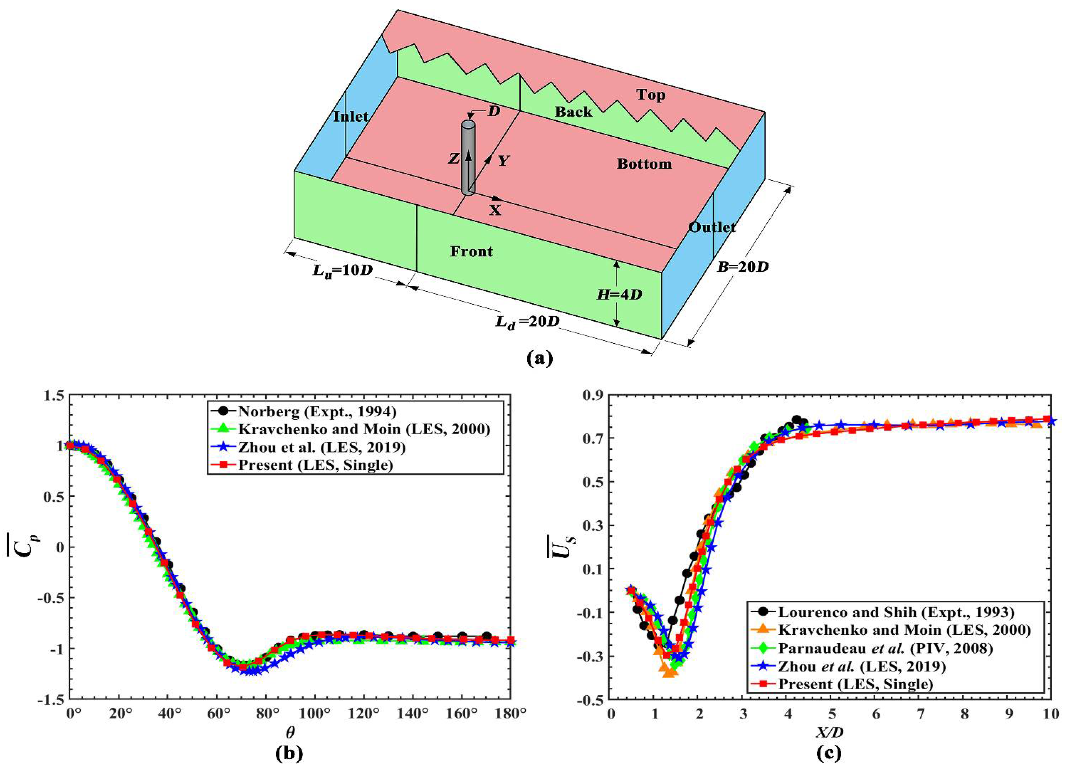
Figure 2.
(a, c, e) Comparison of the normalized spanwise-averaged time-averaged streamwise velocity, and (b, d, f) Comparison of the normalized spanwise-averaged fluctuating streamwise velocity at three cross-sections.
Figure 2.
(a, c, e) Comparison of the normalized spanwise-averaged time-averaged streamwise velocity, and (b, d, f) Comparison of the normalized spanwise-averaged fluctuating streamwise velocity at three cross-sections.
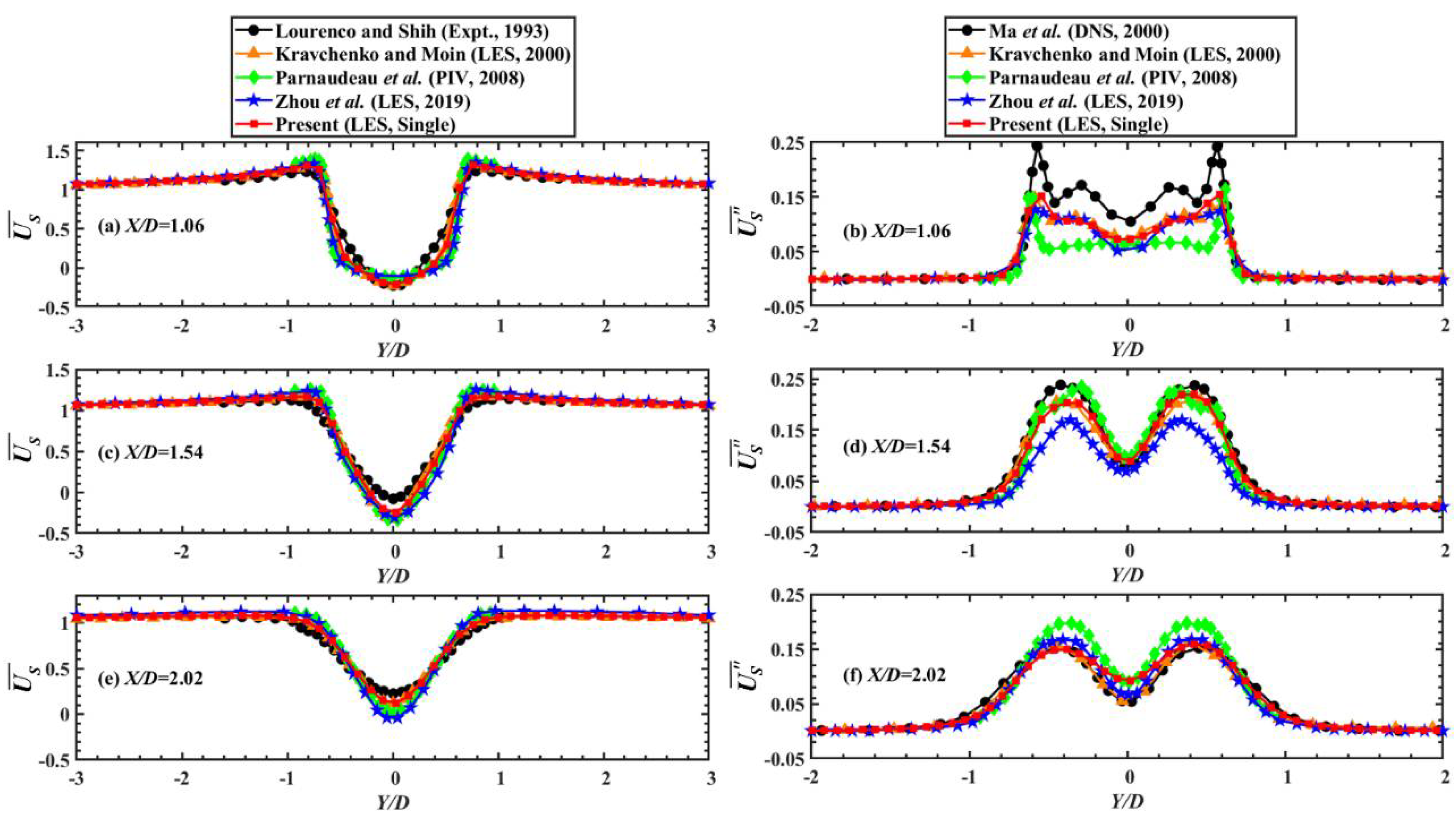
Figure 3.
(a) The 3D computational domain, (b) The 2D computational grids in the X-Y plane, and (c) Close-up view around two tandem circular cylinders for different research cases.
Figure 3.
(a) The 3D computational domain, (b) The 2D computational grids in the X-Y plane, and (c) Close-up view around two tandem circular cylinders for different research cases.
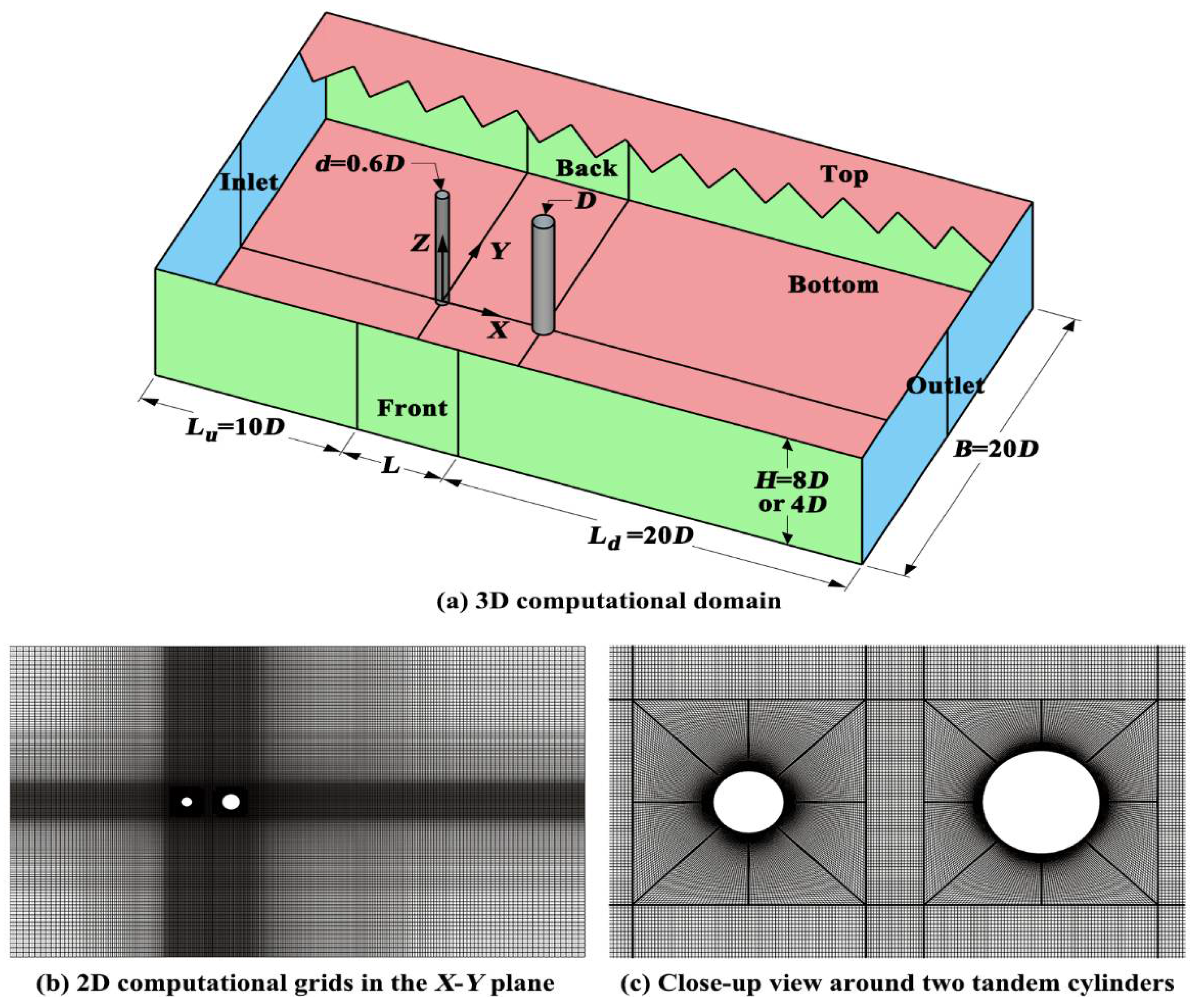
Figure 4.
Small-scale Periodic Reattachment Flow (L/D=1.00~1.50): (a, d, g, j, m, p) The instantaneous spanwise vorticity () contours in the mid-height plane, (b, e, h, k, n, q) The time-averaged spanwise vorticity () contours in the transverse plane, and (c, f, i, l, o, r) The time-averaged Q-criterion iso-surfaces within the gap.
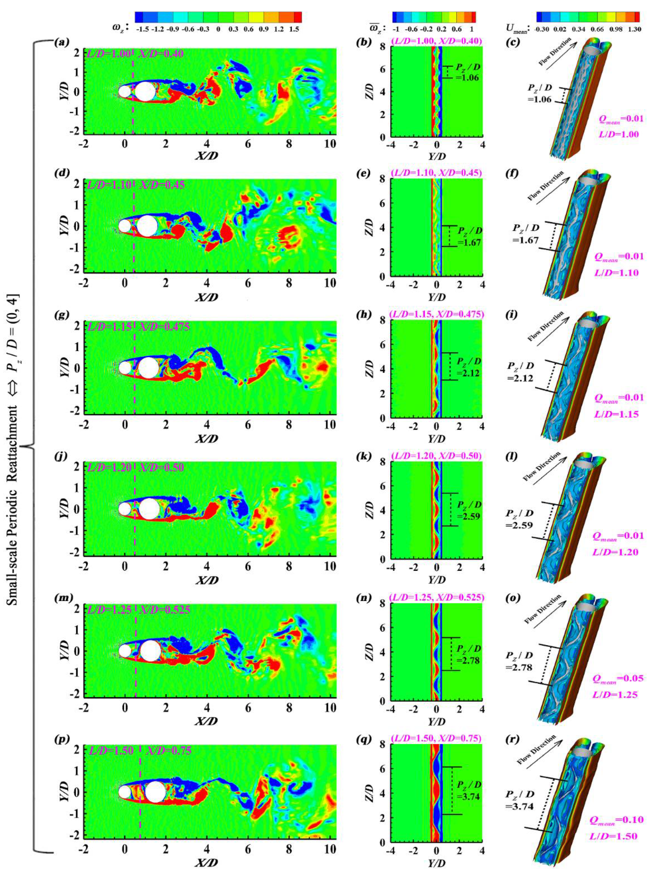
Figure 5.
Small-scale Periodic Reattachment Flow (L/D=1.00~1.50): (a, c, e, g, i, k) The time-averaged streamwise velocity (Umean) contours in the transverse plane, and (b,d, f, h, j, l) St based on the spanwise-averaged instantaneous lift coefficient.
Figure 5.
Small-scale Periodic Reattachment Flow (L/D=1.00~1.50): (a, c, e, g, i, k) The time-averaged streamwise velocity (Umean) contours in the transverse plane, and (b,d, f, h, j, l) St based on the spanwise-averaged instantaneous lift coefficient.
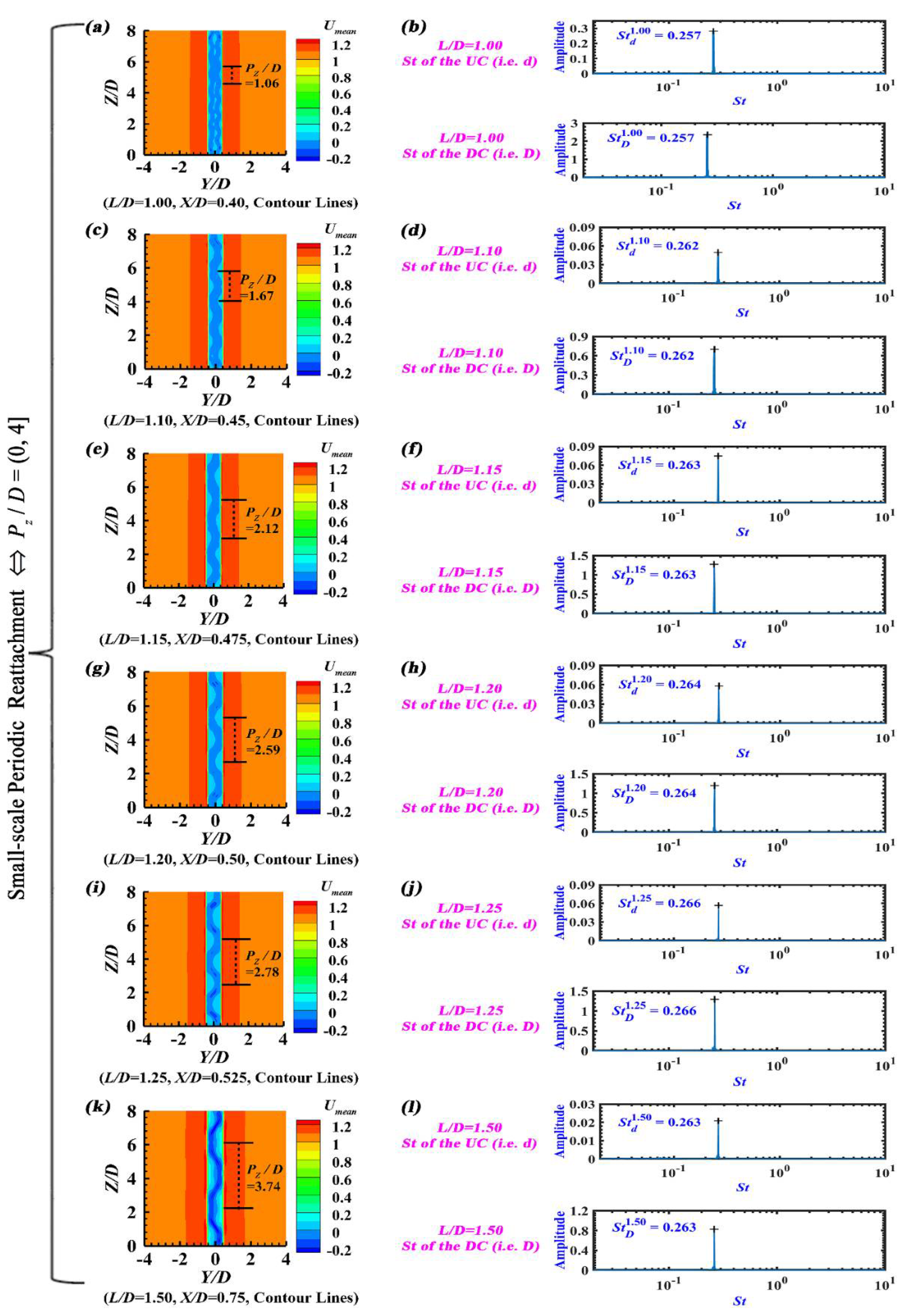
Figure 6.
Large-scale Periodic Reattachment Flow (L/D=2.00~2.25): (a, d) The instantaneous spanwise vorticity () contours in the mid-height plane, (b, e) The time-averaged spanwise vorticity () contours in the transverse plane, and (c, f) The time-averaged Q-criterion iso-surfaces within the gap.
Figure 6.
Large-scale Periodic Reattachment Flow (L/D=2.00~2.25): (a, d) The instantaneous spanwise vorticity () contours in the mid-height plane, (b, e) The time-averaged spanwise vorticity () contours in the transverse plane, and (c, f) The time-averaged Q-criterion iso-surfaces within the gap.
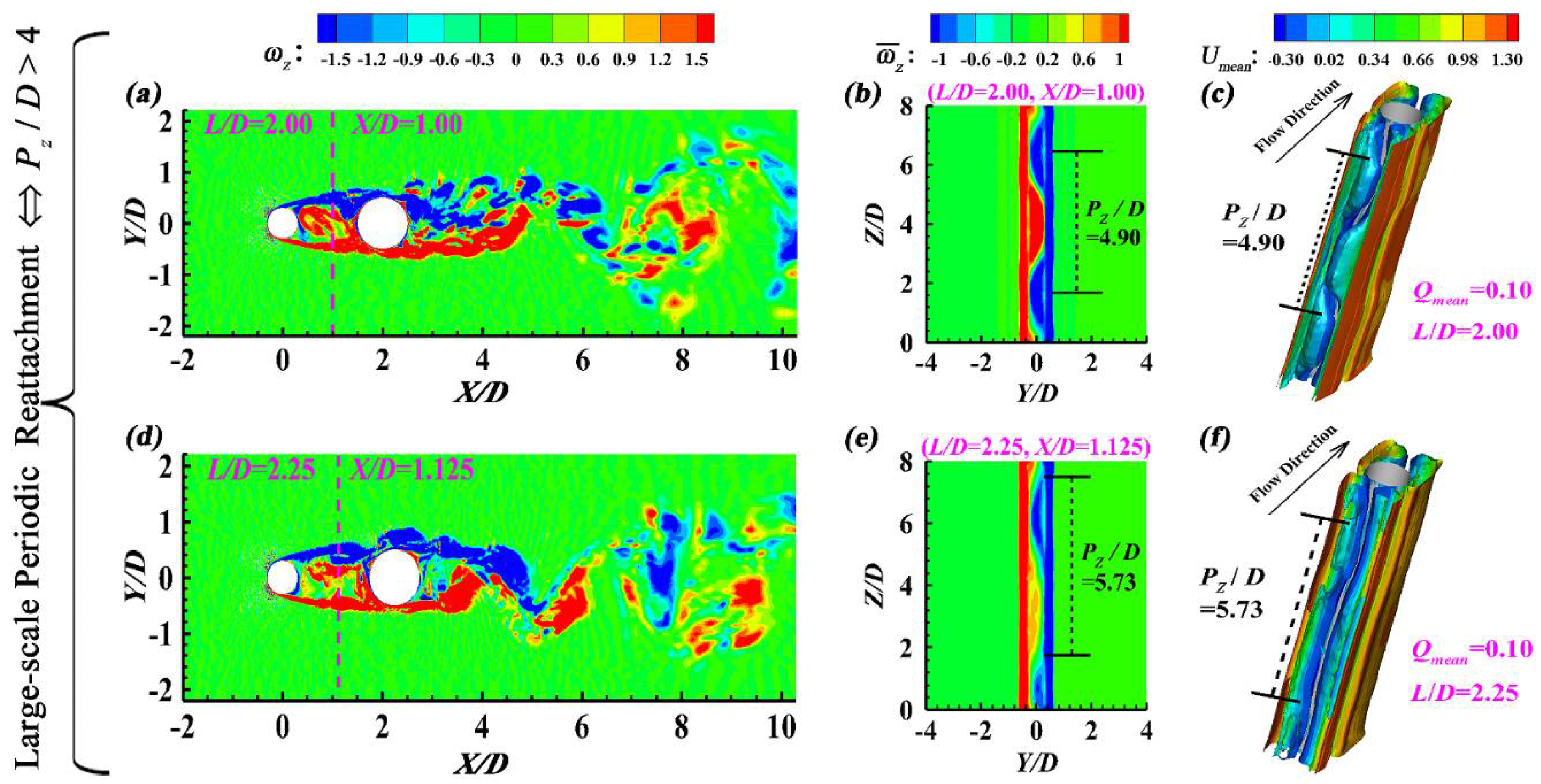
Figure 7.
Large-scale Periodic Reattachment Flow (L/D=2.00~2.25): (a, c) The time-averaged streamwise velocity (Umean) contours in the transverse plane, and (b, d) St based on the spanwise-averaged instantaneous lift coefficient.
Figure 7.
Large-scale Periodic Reattachment Flow (L/D=2.00~2.25): (a, c) The time-averaged streamwise velocity (Umean) contours in the transverse plane, and (b, d) St based on the spanwise-averaged instantaneous lift coefficient.
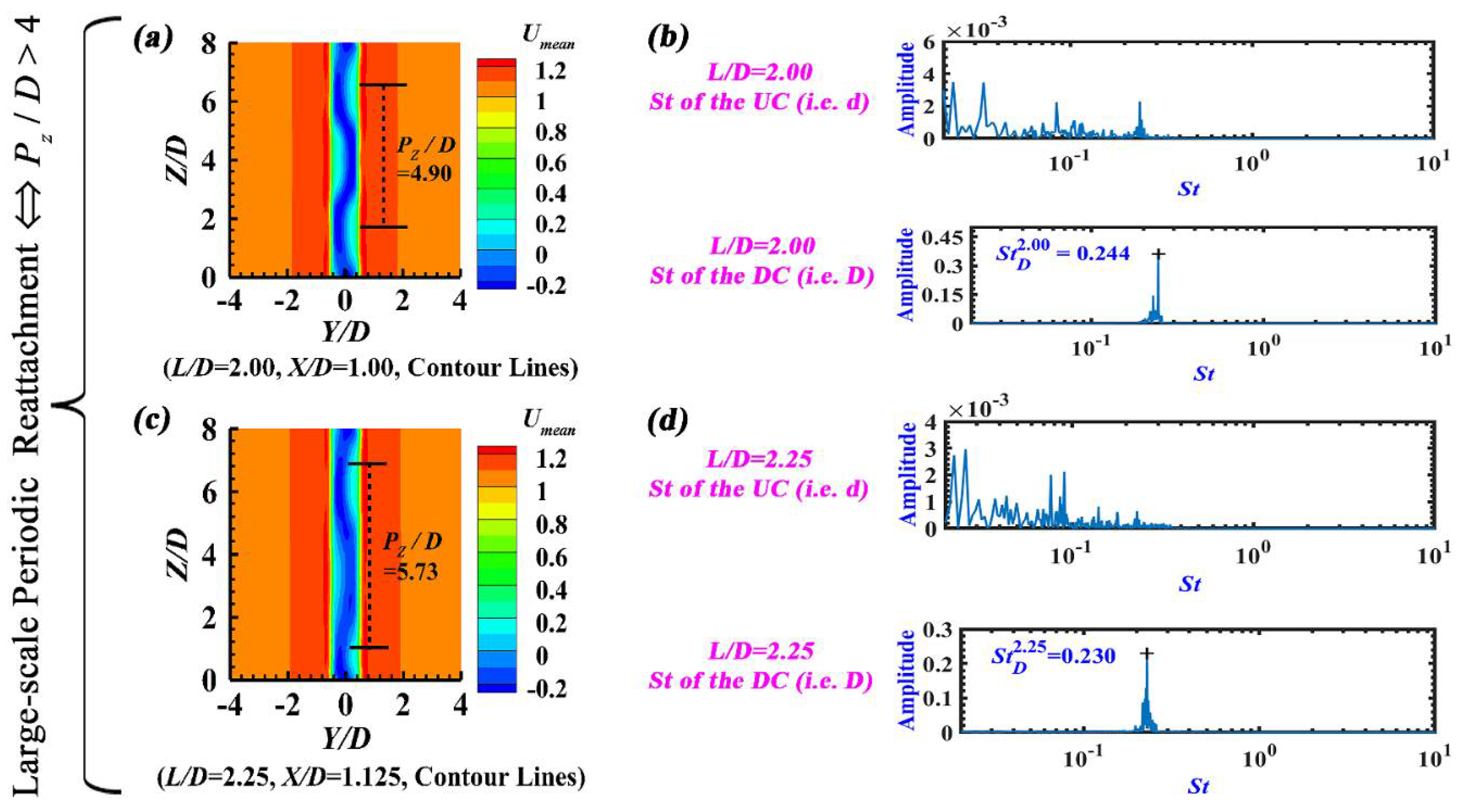
Figure 8.
The asymmetry in horizontal planes for L/D=1.50 & 2.00: (a, b, c, d, e, f) The time-averaged streamwise velocity contours at different heights, and (g, h) The spanwise-averaged time-averaged streamwise velocity contours.
Figure 8.
The asymmetry in horizontal planes for L/D=1.50 & 2.00: (a, b, c, d, e, f) The time-averaged streamwise velocity contours at different heights, and (g, h) The spanwise-averaged time-averaged streamwise velocity contours.
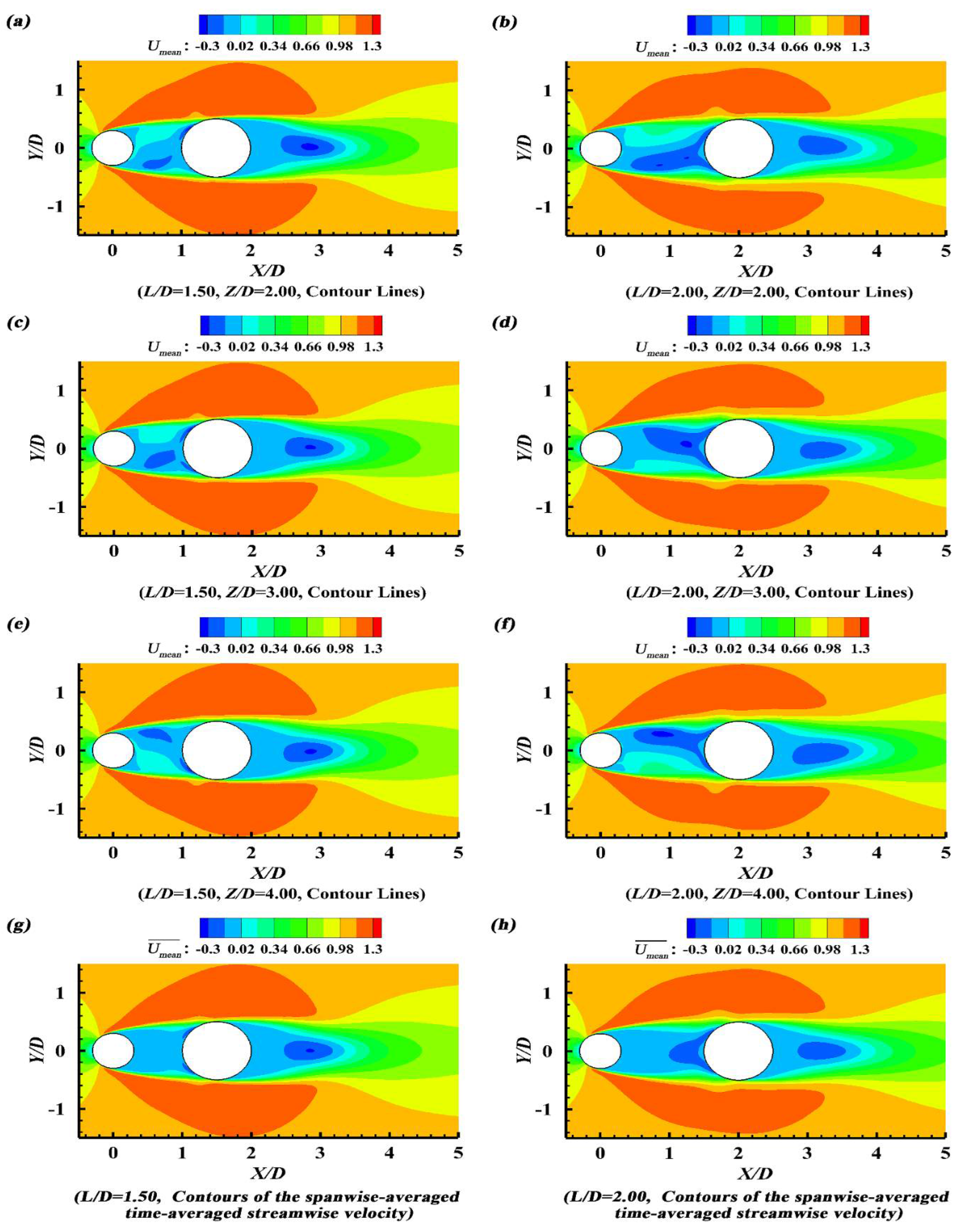
Figure 9.
Non-periodic Reattachment Flow (L/D=2.50~3.15): (a, d, g) The instantaneous spanwise vorticity () contours in the mid-height plane, (b, e, h) The time-averaged spanwise vorticity () contours in the transverse plane, and (c, f, i) The time-averaged Q-criterion iso-surfaces within the gap.
Figure 9.
Non-periodic Reattachment Flow (L/D=2.50~3.15): (a, d, g) The instantaneous spanwise vorticity () contours in the mid-height plane, (b, e, h) The time-averaged spanwise vorticity () contours in the transverse plane, and (c, f, i) The time-averaged Q-criterion iso-surfaces within the gap.
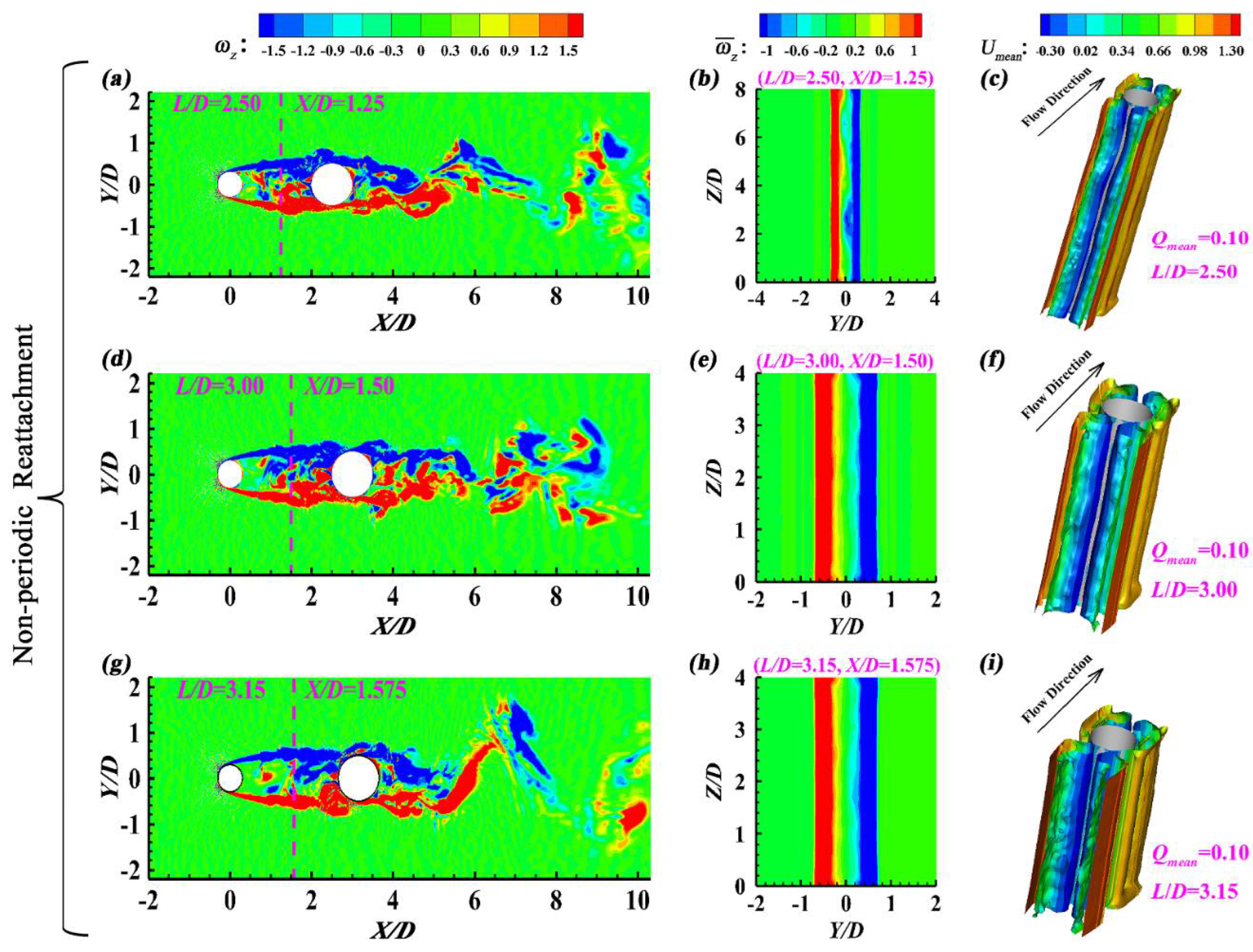
Figure 10.
Non-periodic Reattachment Flow (L/D=2.50~3.15): (a, c, e) The time-averaged streamwise velocity (Umean) contours in the transverse plane, and (b, d, f) St based on the spanwise-averaged instantaneous lift coefficient.
Figure 10.
Non-periodic Reattachment Flow (L/D=2.50~3.15): (a, c, e) The time-averaged streamwise velocity (Umean) contours in the transverse plane, and (b, d, f) St based on the spanwise-averaged instantaneous lift coefficient.
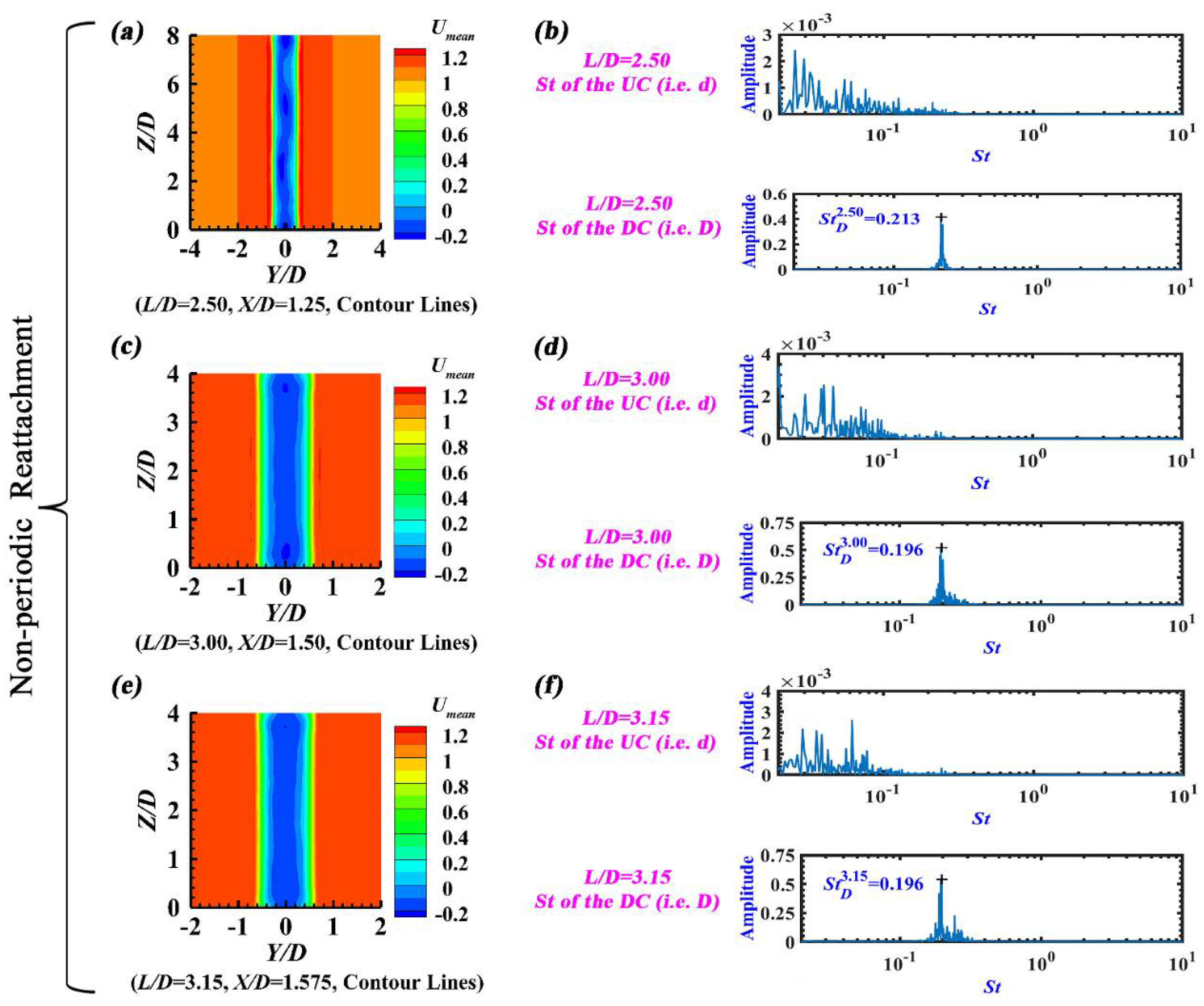
Figure 11.
Bi-stable Flow (L/D=3.24): (a, b, c, d) The instantaneous spanwise vorticity contours in the mid-height plane, (e) The time-averaged spanwise vorticity contours in the transverse plane, (f) The time-averaged Q-criterion iso-surfaces, (g) The time-averaged streamwise velocity contours in the transverse plane, (h) St obtained by Fast Fourier Transform, and (i, j) The wavelet scalogram of the spanwise-averaged instantaneous lift coefficient.
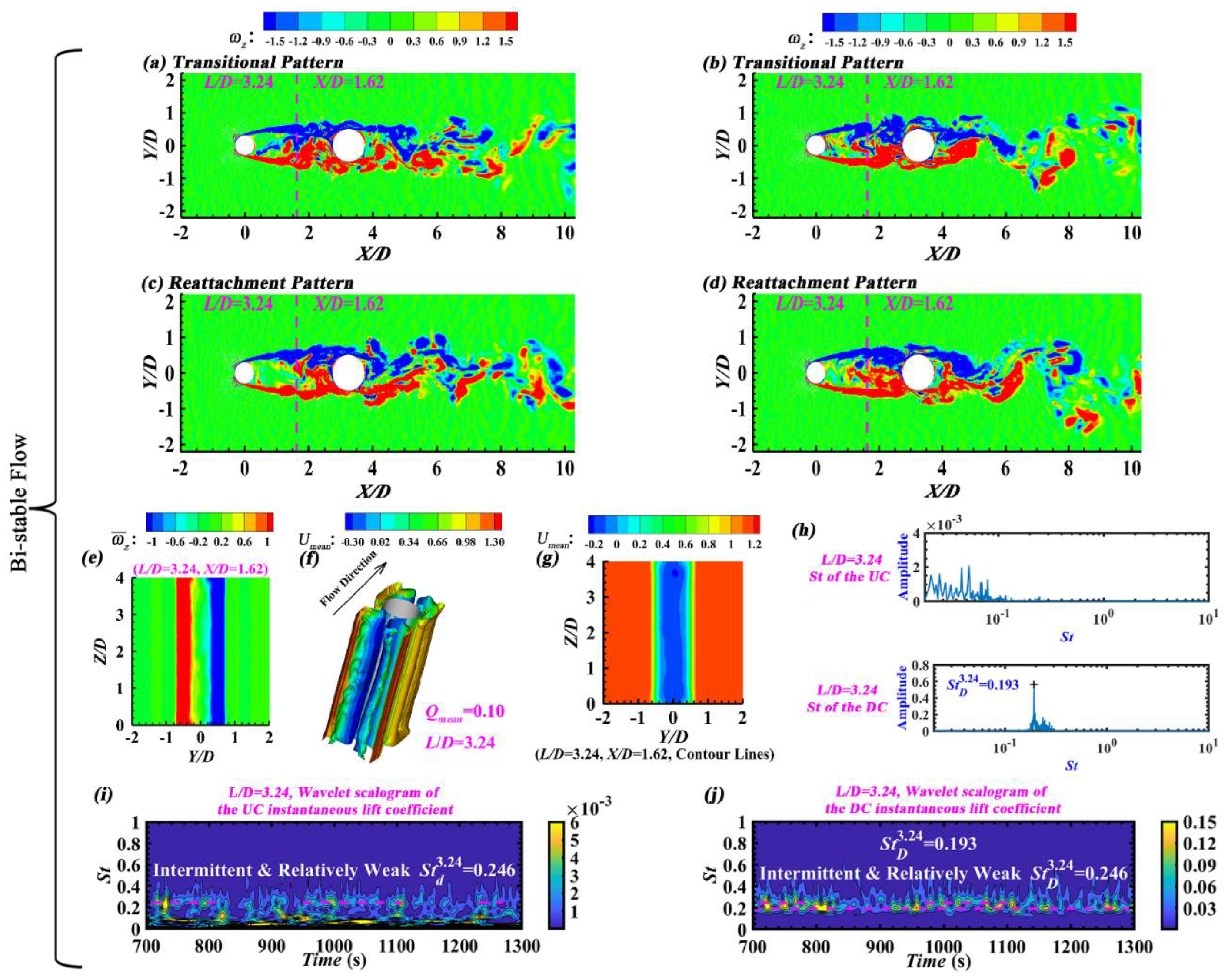
Figure 12.
Co-shedding Flow (L/D=3.30~6.00): (a, d, g, j, m) The instantaneous spanwise vorticity () contours in the mid-height plane, (b, e, h, k, n) The time-averaged spanwise vorticity () contours in the transverse plane, and (c, f, i, l, o) The time-averaged Q-criterion iso-surfaces within the gap.
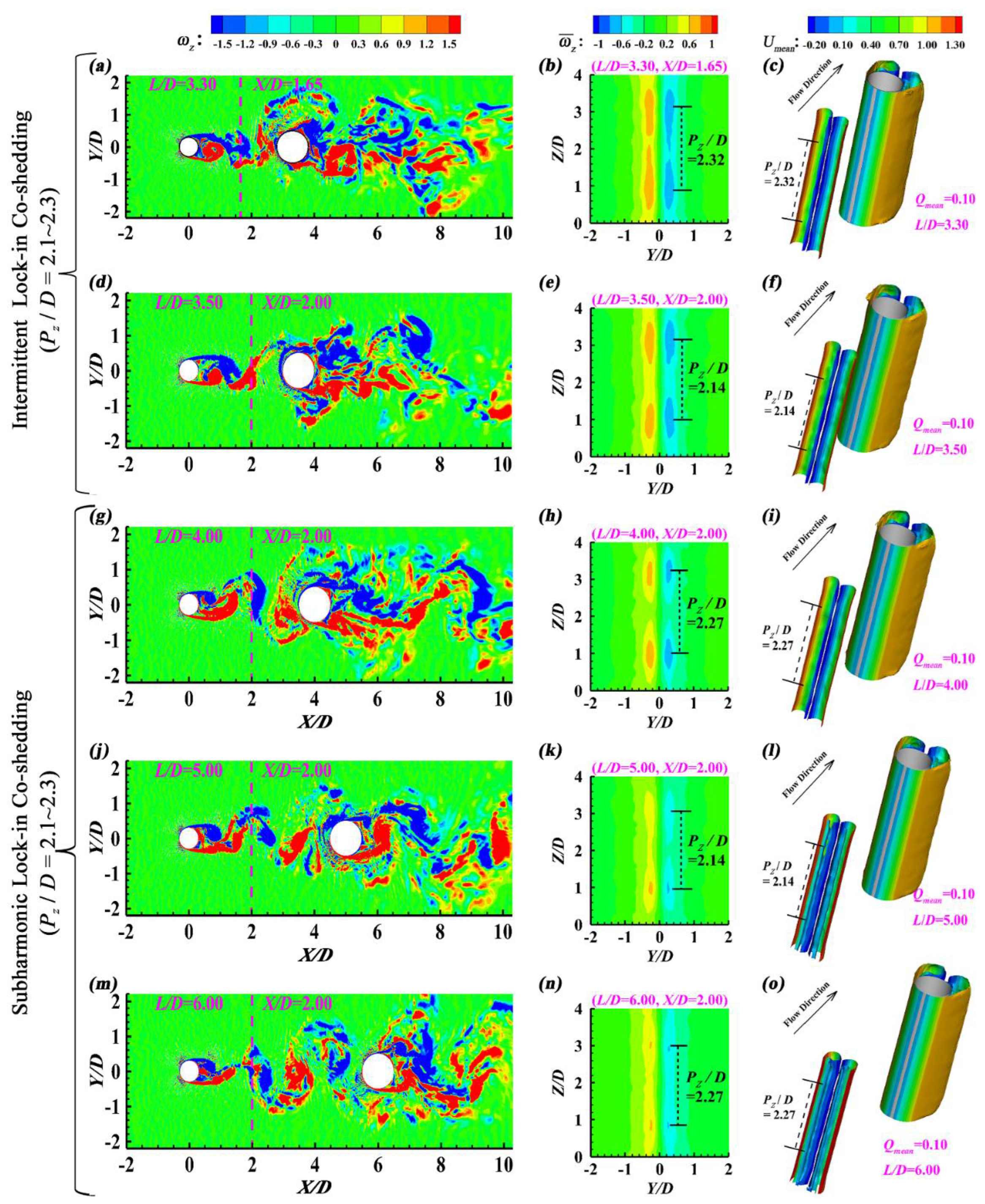
Figure 13.
Co-shedding Flow (L/D=3.30~6.00): (a, c, e, g, i) The time-averaged streamwise velocity (Umean) contours in the transverse plane, and (b, d, f, h, j) St based on the spanwise-averaged instantaneous lift coefficient.
Figure 13.
Co-shedding Flow (L/D=3.30~6.00): (a, c, e, g, i) The time-averaged streamwise velocity (Umean) contours in the transverse plane, and (b, d, f, h, j) St based on the spanwise-averaged instantaneous lift coefficient.
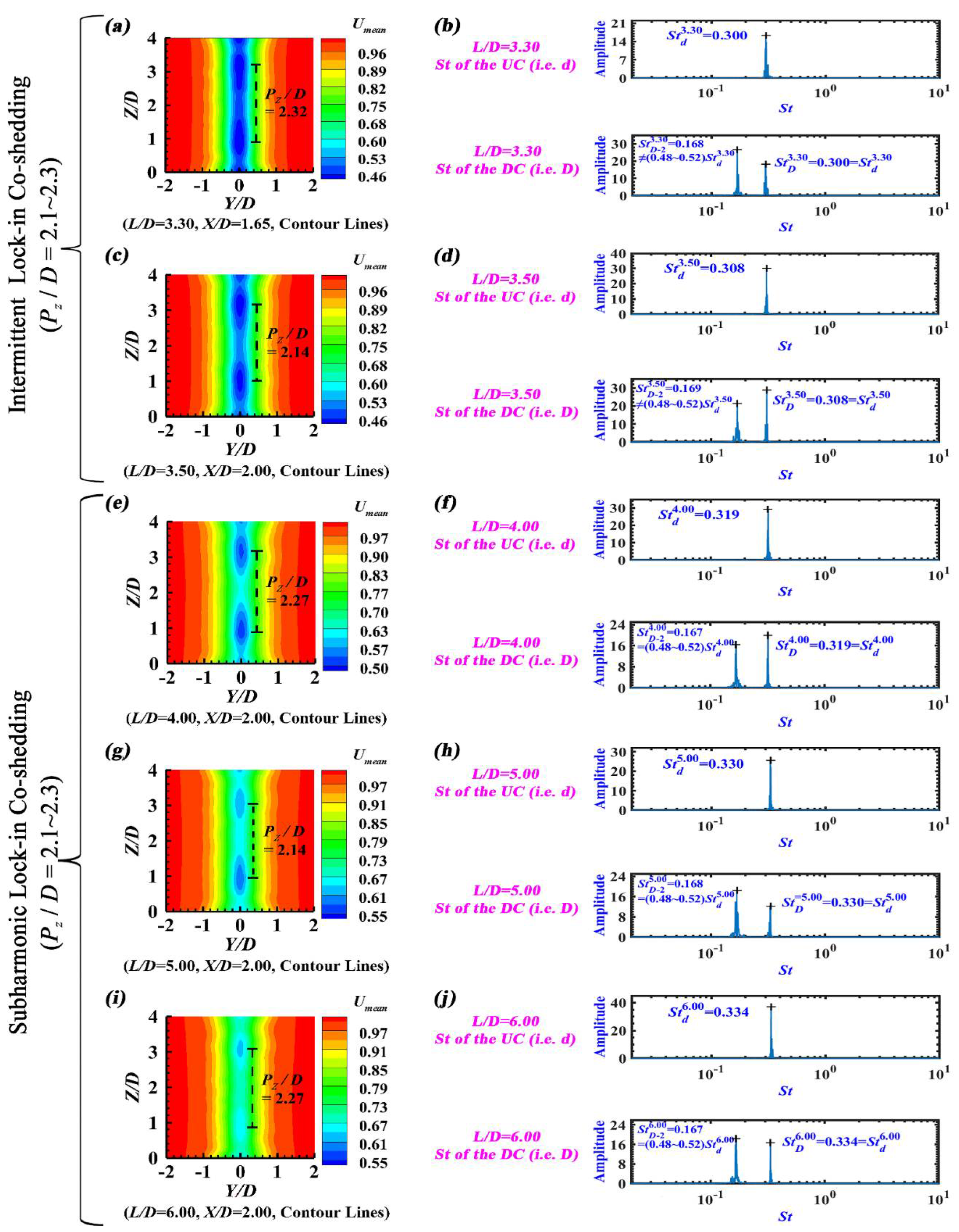

Table 1.
Computational grid characteristics of both the validation case and the seventeen research cases.
Table 1.
Computational grid characteristics of both the validation case and the seventeen research cases.
| Case | Computational domain | Time step ∆t (s) | δ/D | NC | NLu | NL | NLd | NZ | Total node number (✕106) |
| Single Cylinder | 30.00D×20D×4D | 0.0020 | 0.002 | 280 | 113 | / | 230 | 61 | 5.74 |
| L/D=1.00 | 31.00D×20D×8D | 0.0015 | 0.002 | 280 | 134 | 98 | 230 | 121 | 15.45 |
| L/D=1.10 | 31.10D×20D×8D | 0.0015 | 0.002 | 280 | 134 | 106 | 230 | 121 | 17.16 |
| L/D=1.15 | 31.15D×20D×8D | 0.0015 | 0.002 | 280 | 134 | 106 | 230 | 121 | 17.16 |
| L/D=1.20 | 31.20D×20D×8D | 0.0015 | 0.002 | 280 | 134 | 112 | 230 | 121 | 17.45 |
| L/D=1.25 | 31.25D×20D×8D | 0.0015 | 0.002 | 280 | 134 | 112 | 230 | 121 | 17.45 |
| L/D=1.50 | 31.50D×20D×8D | 0.0015 | 0.002 | 280 | 136 | 131 | 230 | 121 | 17.49 |
| L/D=2.00 | 32.00D×20D×8D | 0.0015 | 0.002 | 280 | 113 | 186 | 230 | 121 | 16.03 |
| L/D=2.25 | 32.25D×20D×8D | 0.0015 | 0.002 | 280 | 113 | 208 | 230 | 121 | 16.69 |
| L/D=2.50 | 32.50D×20D×8D | 0.0015 | 0.002 | 280 | 113 | 217 | 230 | 121 | 16.93 |
| L/D=3.00 | 33.00D×20D×4D | 0.0015 | 0.002 | 280 | 113 | 237 | 230 | 61 | 8.81 |
| L/D=3.15 | 33.15D×20D×4D | 0.0015 | 0.002 | 280 | 113 | 244 | 230 | 61 | 8.90 |
| L/D=3.24 | 33.24D×20D×4D | 0.0015 | 0.002 | 280 | 113 | 248 | 230 | 61 | 8.96 |
| L/D=3.30 | 33.30D×20D×4D | 0.0015 | 0.002 | 280 | 113 | 249 | 230 | 61 | 8.97 |
| L/D=3.50 | 33.50D×20D×4D | 0.0015 | 0.002 | 280 | 113 | 255 | 230 | 61 | 9.05 |
| L/D=4.00 | 34.00D×20D×4D | 0.0015 | 0.002 | 280 | 113 | 272 | 230 | 61 | 9.28 |
| L/D=5.00 | 35.00D×20D×4D | 0.0015 | 0.002 | 280 | 113 | 307 | 230 | 61 | 9.75 |
| L/D=6.00 | 36.00D×20D×4D | 0.0015 | 0.002 | 280 | 113 | 342 | 230 | 61 | 10.23 |
Table 2.
Comparison of the Strouhal number (St) based on the spanwise-averaged instantaneous lift coefficient, the spanwise-averaged time-averaged drag coefficient (), the spanwise-averaged fluctuating lift coefficient (), the spanwise-averaged time-averaged base pressure coefficient (), the normalized spanwise-averaged time-averaged recirculation length (Lr/D), the spanwise-averaged time-averaged separation angle () and the normalized spanwise-averaged time-averaged minimum streamwise velocity () along the Y=0 line for the validation case.
| Case | Re | St | Lr/D | |||||
| Present (LES) | 3900 | 0.210 | 1.030 | 0.170 | -0.917 | 1.374 | 87.25° | -0.299 |
| Zhou et al. [40] (LES) | 3900 | 0.217 | 1.000 | / | -0.890 | 1.550 | / | / |
| Tian and Xiao [41] (LES) | 3900 | / | 1.040 | 0.170 | -0.890 | 1.400 | 87.0° | / |
| Kravchenko and Moin [49] (LES) | 3900 | 0.210 | 1.040 | / | -0.940 | 1.350 | 88.0° | -0.370 |
| Parnaudeau et al. [50] (Expt.) | 3900 | 0.208 | / | / | / | 1.510 | / | -0.340 |
| Meyer et al. [51] (LES) | 3900 | 0.210 | 1.050 | / | -0.920 | 1.380 | 88.0° | / |
| Young and Ooi [52] (LES) | 3900 | 0.212 | 1.030 | 0.177 | -0.908 | / | / | / |
| Dong et al. [53] (Expt.) | 4000 | / | / | / | / | 1.470 | / | -0.252 |
| Dong et al. [53] (DNS) | 3900 | 0.208 | / | / | -0.930 | 1.360 | / | -0.291 |
| Rajani et al. [54] (LES, SSM) | 3900 | 0.214 | 1.050 | / | -0.928 | 1.211 | 87.5° | -0.270 |
| Rajani et al. [54] (LES, DSM) | 3900 | 0.210 | 1.010 | / | -0.900 | 1.198 | 87.5° | -0.280 |
| Jiang and Cheng [55] (LES) | 3900 | 0.212 | 0.994 | 0.161 | -0.893 | 1.444 | / | / |
| Lysenko et al. [56] (LES, SMAG) | 3900 | 0.190 | 1.180 | 0.440 | -0.800 | 0.900 | 89.0° | -0.260 |
| Lysenko et al. [56] (LES, TKE) | 3900 | 0.209 | 0.970 | 0.090 | -0.910 | 1.670 | 88.0° | -0.270 |
| Wornom et al. [57] (LES) | 3900 | 0.210 | 0.990 | 0.108 | -0.880 | 1.450 | 89.0° | / |
| Franke and Frank [58] (LES) | 3900 | 0.209 | 0.978 | / | -0.850 | 1.640 | 88.2° | / |
Table 3.
Classification of flow regimes, and comparison of the spanwise periodicity length (Pz/D) within the gap, the Strouhal number (Std or StD) based on the spanwise-averaged instantaneous lift coefficient, the spanwise-averaged time-averaged drag coefficient ( or ), the spanwise-averaged time-averaged separation angle ( or ) and the spanwise-averaged time-averaged reattachment angle of the DC () for all the seventeen research cases.
| Flow Regime | Case | Pz/D | Std | StD | |||||
| Small-scale Periodic Reattachment | L/D=1.00 | 1.06 | 0.257 | 0.257 | 0.751 | 0.237 | 86.10° | 57.86° | 98.55° |
| L/D=1.10 | 1.67 | 0.262 | 0.262 | 0.757 | 0.201 | 86.21° | 60.05° | 98.93° | |
| L/D=1.15 | 2.12 | 0.263 | 0.263 | 0.762 | 0.186 | 86.24° | 60.15° | 100.08° | |
| L/D=1.20 | 2.59 | 0.264 | 0.264 | 0.765 | 0.173 | 86.25° | 60.30° | 100.26° | |
| L/D=1.25 | 2.78 | 0.266 | 0.266 | 0.766 | 0.156 | 86.26° | 60.46° | 100.40° | |
| L/D=1.50 | 3.74 | 0.263 | 0.263 | 0.777 | 0.129 | 86.26° | 59.01° | 101.92° | |
| Large-scale Periodic Reattachment | L/D=2.00 | 4.90 | / | 0.244 | 0.759 | 0.136 | 86.14° | 55.04° | 104.31° |
| L/D=2.25 | 5.73 | / | 0.230 | 0.748 | 0.134 | 86.11° | 53.97° | 105.15° | |
| Non-periodic Reattachment | L/D=2.50 | / | / | 0.213 | 0.738 | 0.146 | 86.08° | 53.74° | 105.46° |
| L/D=3.00 | / | / | 0.196 | 0.724 | 0.170 | 86.05° | 52.78° | 106.91° | |
| L/D=3.15 | / | / | 0.196 | 0.721 | 0.186 | 86.04° | 52.54° | 107.51° | |
| Bi-stable Flow | L/D=3.24 | / | / (0.246)a |
0.193 (0.246)b |
0.719 | 0.188 | 86.03° | 51.45° | 107.54° |
|
Intermittent Lock-in Co-shedding |
L/D=3.30 | 2.32 | 0.300 | 0.300 & 0.168 |
1.048 | 0.698 | 91.00° | / | 97.97° |
| L/D=3.50 | 2.14 | 0.308 | 0.308 & 0.169 |
1.050 | 0.702 | 91.00° | / | 97.76° | |
|
Subharmonic Lock-in Co-shedding |
L/D=4.00 | 2.27 | 0.319 | 0.319 & 0.167 |
1.098 | 0.707 | 91.23° | / | 96.49° |
| L/D=5.00 | 2.14 | 0.330 | 0.330 & 0.168 |
1.104 | 0.764 | 91.21° | / | 96.29° | |
| L/D=6.00 | 2.27 | 0.334 | 0.334 & 0.167 |
1.115 | 0.787 | 91.22° | / | 96.11° |
a, b) For L/D=3.24, when implementing the Fast Fourier Transform of the spanwise-averaged instantaneous lift coefficient, no dominant St is observed for the UC, and only one dominant St is recognized for the DC (i.e. StD=0.193, Figure 11(h)). However, an intermittent and relatively weak St (i.e. Std=StD=0.246) is visible for both cylinders in the wavelet scalogram (Figure 11(i, j)), corresponding to the transitional pattern of Bi-stable Flow.
Disclaimer/Publisher’s Note: The statements, opinions and data contained in all publications are solely those of the individual author(s) and contributor(s) and not of MDPI and/or the editor(s). MDPI and/or the editor(s) disclaim responsibility for any injury to people or property resulting from any ideas, methods, instructions or products referred to in the content. |
© 2024 by the authors. Licensee MDPI, Basel, Switzerland. This article is an open access article distributed under the terms and conditions of the Creative Commons Attribution (CC BY) license (http://creativecommons.org/licenses/by/4.0/).
Copyright: This open access article is published under a Creative Commons CC BY 4.0 license, which permit the free download, distribution, and reuse, provided that the author and preprint are cited in any reuse.


