Submitted:
12 March 2024
Posted:
26 March 2024
You are already at the latest version
Abstract
Keywords:
1. Introduction
2. AR-HCF Is Designed to Transmit 2.79 μm Band Laser
3. Parameter Optimization
3.1. Effect of Capillary Wall Thickness on AR-HCF Transmission Characteristics
3.2. Influence of Capillary Inner Diameter on AR-HCF Transmission Characteristics
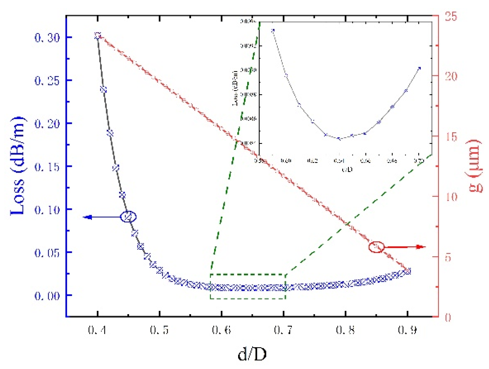
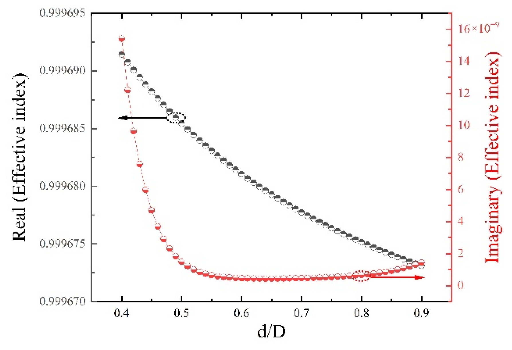
3.3. Influence of Fiber Core Diameter on AR-HCF Transmission Characteristics
4. Results and Discussion
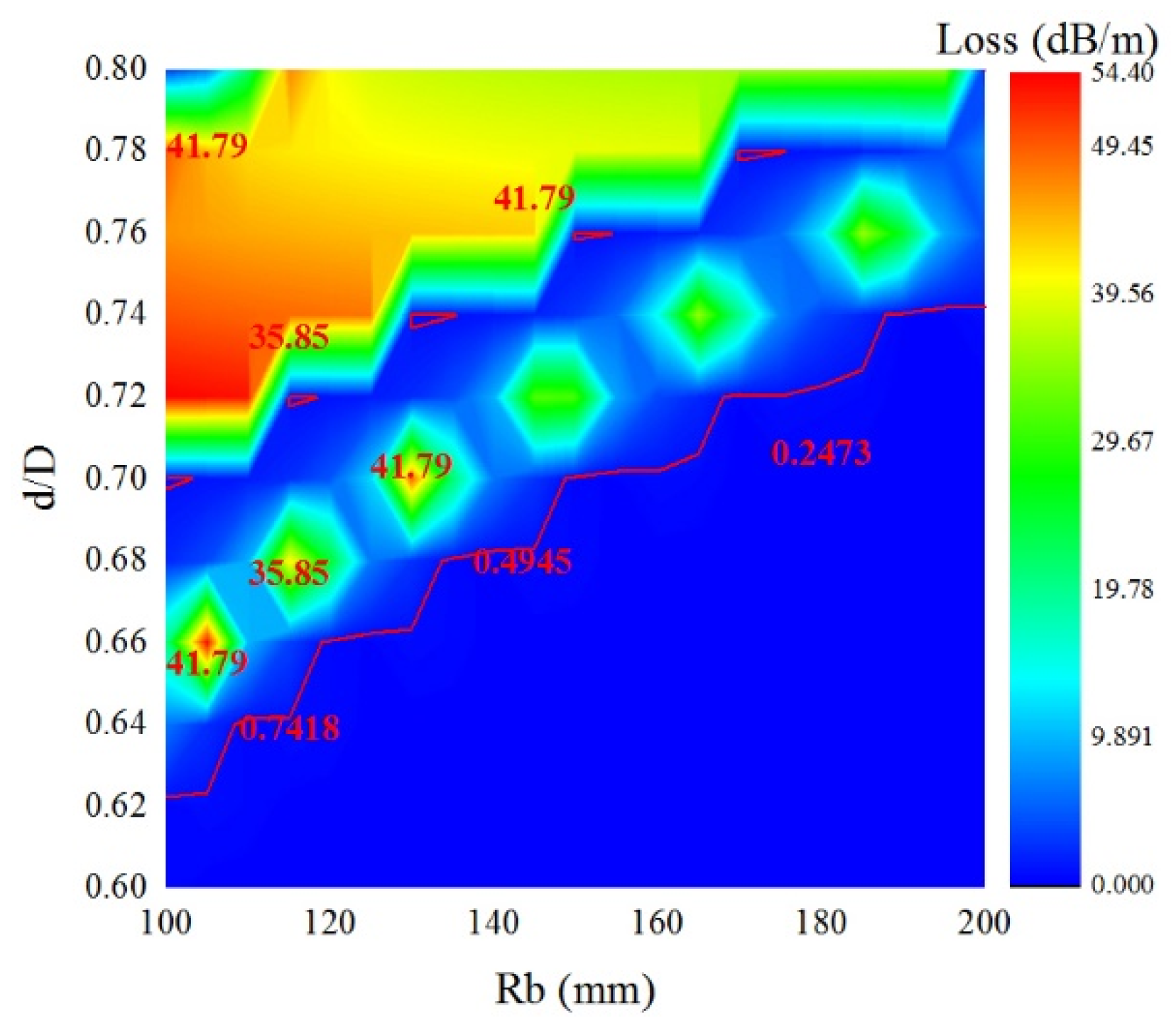
4.1. Influence of Inner Diameter of Casing on Bending Loss
4.2. Influence of Capillary Gap on Bending Loss
5. Conclusions
Author Contributions
Funding
Institutional Review Board Statement
Informed Consent Statement
Data Availability Statement
Conflicts of Interest
References
- Zheng, d., X.; Ling, L., J.; Ting, Q., C.; Hai, h., J. 100 Hz repetition-rate 2.794 μm Cr,Er:YSGG passively Q-switched laser with Fe2+:ZnSe saturable absorber. Infrared Physics and Technology 2022, 122, 104087.
- Guo, B.; Xiao, Q. L.; Wang, S. H. 2D layered materials: synthesis, nonlinear optical properties, and device applications. Laser and Photonics Reviews 2019, 13, 1800327. [Google Scholar] [CrossRef]
- N. J. Scott; R. A. Barton; A. L. Casperson, A.; T., K.; Levin, D. Tran; N. M. Fried. Mid-IR germanium oxide fibers for contact erbium laser tissue ablation in endoscopic surgery. IEEE J. Sel. Top. Quantum Electron. 2007, 13, 1709–1714. [CrossRef]
- N. M. Fried; Y. B. Yang; C. A. Chaney; D. Fried. Transmission of Q-switched Er :YSGG (λ=2.79 µm) and Er: YAG (λ=2.94 µm) laser radiation through germanium oxide and sapphire optical fibers at high pulse energies. Lasers Med. Sci. 2004, 19, 155–160. [CrossRef] [PubMed]
- Andrey, D. P.; Alexander S., B.; Alexey, F. K.; Victor, G. P.; Sergei L., S. ; E. M. D. Demonstration of a waveguide regime for a silica hollow - core micro-structured optical fiber with a negative curvature of the core boundary in the spectral region > 3.5 μm. Opt. Express 2011, 19, 1441–1448. [Google Scholar]
- Md. Selim, Habib; Ole, Bang; and Morten, Bache. Low-loss single-mode hollow-core fiber with anisotropic anti-resonant elements. Opt. Express 2016, 24, 8429–8436. [CrossRef] [PubMed]
- J. B.; S. E. B.; Thomas, S.; Anders B. Analysis of air-guiding photonic bandgap fibers. Opt. Lett. 2000, 25, 96–98. [CrossRef] [PubMed]
- G. J. Pearce; J. M. Pottage; D. M. Bird; P. J. Roberts; J. C. Knight; and P. St.J. Russell. Hollow-core PCF for guidance in the mid to far infra-red. Opt. Express 2005, 13, 6937–6946. [CrossRef]
- Jonathan, Hu; Curtis, R. M. Leakage loss and bandgap analysis in air-core photonic band gap fiber for nonsilica glasses. Opt. Express 2007, 15, 339–349. [CrossRef]
- Shuai, G.; Xin, W.; Hao, Q. J.; Zhen, X.; Shu, Q. L. Single-mode bend-resistant hollow-core fiber with multi-size anti-resonant elements. Infrared Physics and Technology 2022, 123, 104159. [Google Scholar]
- Liang, L.; Guan, J.; Zhu, X.; Wang, Y.; Wu, D.; Yu, F.; Han, Y. Delivery of Nearly Diffraction-Limited Picosecond Laser Pulses in the Air-Filled Anti-Resonant Hollow-Core Fiber at 1 μm Wavelength. Photonics 2023, 10, 416. [Google Scholar] [CrossRef]
- Xing, t. Z.; Xuan, R. W.; Xiaobo, L.; Jie, L.; Lei, Z.; Peng, L.; Jing l., X.; Wen b., M.; Shu t., W. 5-tube hollow-core anti-resonant fiber with ultralow loss and single mode. Optics Communications 2021, 501, 127347. [Google Scholar]
- Hua, B. L.; Yu, W.; Yan, Z.; Zu, G. G.; Zhang, W. Y.; Qiang, L.; Si, L.; Jie, S.; Don G., H.; Daru, C. Low bending loss few-mode hollow-core anti-resonant fiber with glass-sheet conjoined nested tubes. Opt. Express 2022, 30, 21833–21842. [Google Scholar]
- Urich; R. R. J. Maier; Fei, Y.; J. C. Knight; D. P. Hand; J. D. Shephard. Flexible delivery of Er: YAG radiation at 2.94 µm with negative curvature silica glass fibers: a new solution for minimally invasive surgical procedures. Biomed. Opt. Express 2013, 4, 193–205. [CrossRef]
- Fei, Y.; William J., Wadsworth; Jonathan, C. Knight. Low loss silica hollow core fibers for 3-4 μm spectral region. Opt. Express 2012, 20, 11153–11158. [Google Scholar]
- Walter, Belardi; Jonathan, C. Knight. Hollow anti resonant fibers with low bending loss. Opt. Express 2014, 22, 10091–10096.
- Mariusz, K.; Dominik, D. ; Amar, Nath, G.; Grzegorz, S.; Dariusz, P.; Guillaume, H.; Thibaut, S.; and R. B. Nested capillary anti-resonant silica fiber with mid-infrared transmission and low bending sensitivity at 4000 nm. Opt. Lett. 2019, 44, 4395–4398. [Google Scholar]
- L. Vincetti and V. Setti. Extra loss due to Fano resonances in inhibited coupling fibers based on a lattice of tubes. Opt. Express 2012, 20, 14350–14361. [Google Scholar] [CrossRef] [PubMed]
- Santos, D. F. ; G. A.; Baptista, J. M. SPR. Microstructured D-Type Optical Fiber Sensor Configuration for Refractive Index Measurement. Sensors Journal IEEE 2015, 15, 5472–5477. [Google Scholar] [CrossRef]
- N. M. L.; A. K. A.; C. Headley; B. J. E. Anti-resonant reflecting photonic crystal optical waveguides. Opt. Lett. 2002, 27, 1592–1594. [CrossRef]
- Shi, B. Y.; Shu, Q. L.; Wan, Z.; Zheng, G. L. Single-polarization single-mode double-ring hollow-core anti-resonant fiber. Opt. Express 2018, 26, 31160–31171. [Google Scholar]
- Da, K. W.; Fei, Y.; Mei, S. L. Understanding the material loss of anti-resonant hollow-core fibers. Opt. Express 2020, 28, 11840–11851. [Google Scholar]
- C., F.; B., F.; Roberts, P. J. Generation; Photonic. Guidance of Multi-Octave Optical-Frequency Combs. Science 2007, 318, 1118–1121. [Google Scholar]
- Francesco, Poletti. Nested anti-resonant nodeless hollow core fiber. Opt. Express 2014, 22, 23807–23828. [CrossRef]
- M. S. Habib; O. Bang; M. Bache. Low-Loss Hollow-Core Anti-Resonant Fibers With Semi-Circular Nested Tubes. IEEE Journal of Selected Topics in Quantum Electronics 2016, 22, 156–161. [Google Scholar] [CrossRef]


Disclaimer/Publisher’s Note: The statements, opinions and data contained in all publications are solely those of the individual author(s) and contributor(s) and not of MDPI and/or the editor(s). MDPI and/or the editor(s) disclaim responsibility for any injury to people or property resulting from any ideas, methods, instructions or products referred to in the content. |
© 2024 by the authors. Licensee MDPI, Basel, Switzerland. This article is an open access article distributed under the terms and conditions of the Creative Commons Attribution (CC BY) license (http://creativecommons.org/licenses/by/4.0/).


