Preprint
Article

Research on the Effect of Carbon Dioxide Miscible Fracturing Huff and Puff in Enhancing Oil Recovery

Altmetrics

Downloads

79

Views

25

Comments

0

A peer-reviewed article of this preprint also exists.

This version is not peer-reviewed

Submitted:

12 March 2024

Posted:

12 March 2024

You are already at the latest version

Alerts
Abstract
Carbon dioxide (CO2)miscible fracturing huff and puff technology plays a pivotal role in enhancing the recovery rate of crude oil, particularly in reservoirs with challenging physical properties, strong water sensitivity, high injection pressure, and complex water injection dynamics. In this study, the oil-increasing mechanism and huff and puff effect of CO2 miscible fracturing fluid are investigated through a comprehensive experimental approach. Specifically, experiments on PVT gas injection expansion, minimum miscible pressure, and CO2 miscible fracturing huff and puff are conducted on the G fault block reservoir in J Oilfield. The findings demonstrate that injecting CO2 into reservoirs leads to oil volume expansion, viscosity reduction, and saturation pressure increase. Additionally, the inclusion of solubilizers and viscosity reducers further enhances the efficiency of crude oil extraction. Solubilizers not only improve oil recovery but also reduce the minimum miscible pressure required for effective CO2 dispersion. Furthermore, the shut-in time, permeability, and huff and puff method all have considerable impacts on huff and puff recovery rate. This study offers valuable technical insights, supporting the application of CO2 miscible fracturing huff and puff technology to enhance oil recovery in low-permeability reservoirs.
Keywords: 
Subject: Engineering  -   Energy and Fuel Technology

1. Introduction

With the exploration and development of oil and gas resources, unconventional oil and gas resources such as low permeability and tightness have become the focus of attention. Low-permeability reservoirs have poor physical properties, tiny pore throats, and severe heterogeneity; water injection is often used in development. High injection pressure, difficulty in water injection, and inability to effectively replenish formation energy result in poor water flooding development outcomes [1]. To enhance the trapped oil production post water/gas injection along with curbing the greenhouse gas emissions encountered by countries, the CO2-EOR method has emerged as a sustainable solution to tackle this situation. It has been shown to lower oil and gas interfacial tension, decrease crude oil viscosity, increase volume, enhance fluidity, alter rock wettability, and enhance oil recovery by injecting CO2 into the reservoir [2,3,4,5]. CO2 is typically injected into the reservoir under miscible situations [6], immiscible front displacement after water flooding [7], water alternating gas(WAG) displacement [8], and CO2 dissolved in brine flooding [9]. In comparison to other hydrocarbon gas injections, the oil recovery values are much better in the CO2 miscible method [10]. Hao et al. [11] inferred that under certain conditions, CO2 and crude oil can be miscible, thereby reducing the viscosity of the formation fluids and enhancing their flow capacity. The oil displacement efficiency of CO2 miscible flooding is affected by many factors. Moghadasi R. et al. [12] inferred that the displacement efficiency during miscible CO2 flooding is also influenced by the mechanisms of oil swelling, the difference in density and viscosity of the displaced and displacing fluids, relative permeabilities, wetting behavior of reservoir rocks, change in injection period with alteration in injection and production rates.
Recently, the huff-n-puff CO2 injection technique has evolved as an efficient means of exploring these unconventional reserves [13,14]. Li et al. [15] conducted PVT experiments to study the changes in crude oil gas-oil ratio, saturation pressure, and crude oil viscosity under different CO2 amounts, and conducted a tight sandstone core CO2 miscible oil displacement experiment. They observed when the CO2 composition was raised from 38.94 mol% to 60 mol%, with GOR changed to 149.5 cm3/cm3 from 59 cm3/cm3, and saturation pressure varied to 8.44MPa from 4.97MPa, consequently, at reservoir temperature, a reduction in the viscosity of dead oil from 10% to 16%, which achieved the highest recovery values for the case with pre-water flooding + CO2 tertiary flooding with CO2 core soaking. But still low oil recovery factors are reported. The oil recovery is largely influenced by the operating parameters, such as the cycle of huff and puff, soaking time, pressure, etc.
Fracturing with CO2 is a rising non-aqueous fracturing technique, which has been widely used in unconventional reservoirs. CO2 has the ability to break rock to form complex fracture networks. Compared with hydraulic fracturing, injecting CO2 can enter tiny pore throats that are difficult for water-based fracturing fluids to enter, significantly improving core permeability. At the same time, it can be miscible with the formation of crude oil, improving the properties of crude oil. Based on this, CO2 miscible fracturing huff and puff technology was proposed. This technology uses high-pressure pump trucks to inject CO2 and chemical agents into the formation. It plays the role of chemical agents in enhancing reservoir and oil properties while fully utilizing the benefits of CO2-stimulated fracturing [16,17,18], replenishing formation energy, and shutting down the well for a certain period before opening the well for production, which is an effective technology for improving crude oil recovery. N. Kumar et al. [19] mentioned the technology of injecting a certain amount of solvent in the process of miscible flooding, but did not give a detailed description. In a study by Permadi et al. [20], they mixed hydroxyl and carbonyl groups with CO2 to experimentally evaluate its influence on MMP and properties like oil swelling, viscosity change, interfacial tension reduction and pressure-volume effect. Lower MMP, IFT, and viscosity values with high swelling effects were observed for the CO2 acetone/propanol mixture, indicating acceleration in CO2-oil dissolution upon solvent addition leading to better oil recoveries. Du et al. [21] construct a high-viscosity CO2 fracturing fluid system with high proppant carrying capability and low fluid leak-off and formation damage rate to solve the application problem of CO2 fracturing fluid in unconventional reservoirs. Gong et al. [22] construct CO2/cosolvent mixed fluids and the experiments of huff and puff were carried out, the results show that CO2/cosolvents can further enhance the shale oil recoveries of the matrix and fracture during the huff and puff process. This shows that CO2 miscible fracturing is feasible to enhance oil recovery, but the mechanism and effect of this technology to enhance oil recovery in low permeability reservoirs need to be further studied, and its adaptability in low permeability reservoirs needs further validation.
Therefore, this article combines the PVT device, slim tube model, and core displacement device to conduct experiments. By conducting interaction experiments between the CO2 miscible fracturing fluid and crude oil to study the impact of different CO2 injection amounts and fracturing fluid additives on oil PVT. By conducting CO2 minimum miscible pressure experiments to study the miscible conditions of the reservoir and the impact of fracturing fluid additives on miscible pressure. By conducting CO2 miscible fracturing huff and puff experiments to study the effect of CO2 miscible fracturing huff and puff, and optimize process parameters. Through these studies, to provide technical support for the application of CO2 miscible fracturing huff and puff technology to enhance oil recovery in low-permeability reservoirs.

2. Experiment

2.1. Experimental Materials

①Oil sample: The crude oil utilized originates from the wellhead of the G fault block reservoir within the J Oilfield. Specifically, we employ a simulated crude oil that has been meticulously prepared based on the ground crude oil and natural gas found in our research area. This preparation takes into account the formation conditions and fluid characteristics. Notably, the gas-to-oil ratio of this simulated crude oil stands at 91.2 m³/m³.
②Gas injected: CO2 gas with a purity of 99.999%.
③Fracturing fluid additives: The solubilizers and viscosity reducers employed belong to the fracturing fluid series additives that are routinely used on-site within the target reservoir. These additives have been developed by the Oil Production Technology Research Institute of the Great Wall Drilling Engineering Technology Research Institute. The concentration dosage for these additives is set at 10%.
④Slim tube: The slim tube with a length of 15 m and a diameter of 4.4 millimeters, exhibits a permeability of 5800 mD and possesses a pore volume of 84.2 mL.
⑤Water: The water employed in this study is sourced directly from the target oil reservoir site. Prior to experimentation, it undergoes filtration using a 0.45 μm filter membrane, facilitated through a sand core funnel.
⑥Core: The core specimens utilized consist of natural rock samples generously supplied by J Oil Field, China. These cores exhibit a permeability range spanning from 4 to 40 mD, and their additional properties are shown in Table 1.

2.2. Experimental Design

The experimental temperature is set to 113.8°C, the pressure is 33MPa, and the fracturing pressure is 55Mpa. Notably, these values align with those observed in the formation reservoir.

2.2.1. Experiment on Gas Injection Expansion

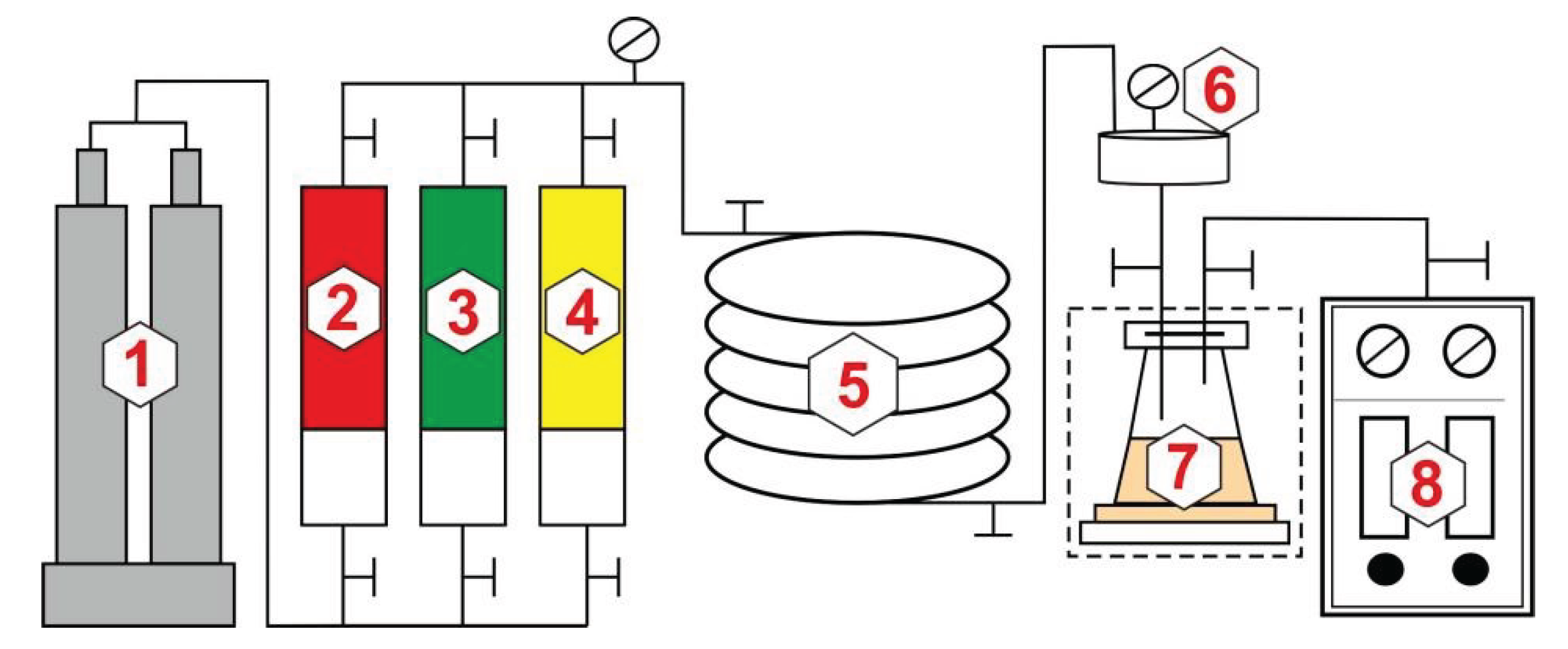
To investigate the impacts of CO2 and fracturing fluid additives on the high-pressure physical properties of crude oil, and clarify the oil-increasing mechanism of CO2 miscible fracturing, the high-pressure physical properties of crude oil and gas injection expansion experiments are conducted. As shown in Figure 1, the PVT experimental device used in conjunction with a high-temperature and high-pressure formation fluid viscometer. The industry standard GB/T 26981-2020 “Oil and Gas Reservoir Fluid Physical Property Analysis Method” is employed as a reference. The experimental procedure is outlined below:
①Add a specified quantity of simulated crude oil into the PVT cylinder. Subsequently, elevate the temperature and pressure to match the reservoir conditions. Precisely measure the resulting oil sample volume. Following this, perform degassing experiments to ascertain both the gas-oil ratio and the volume coefficient of the oil.
②Employ the stepwise pressure reduction method to establish the p-V relationship for the oil sample. At each stable pressure reduction stage, record the corresponding sample volume values. These data points collectively form the p-V relationship curve. The inflection point on this curve corresponds to the bubble point pressure.
③First, compute the required quantity of injected gas (ranging from 10 mol% to 60 mol%) for each stage, considering the composition of the original oil sample. Subsequently, introduce CO2 gas into the PVT cylinder and pressurize it beyond the bubble point pressure. Agitate the sample thoroughly to achieve fluid uniformity. Next, execute the procedures outlined in ② to establish the corresponding p-V relationship curve. Calculate essential properties, including the saturation pressure, density, and volume coefficient. Finally, employ a high-temperature and high-pressure formation fluid viscometer to measure viscosity.
④Following the gas injection experiment, reintroduce a specific quantity of simulated crude oil into the meticulously cleaned PVT cylinder. Additionally, incorporate 0.1 PV of fracturing fluid additives. Subsequently, replicate the procedures outlined in steps ① to ③.Observe and quantify alterations in the high-pressure physical properties of the oil, as well as the characteristic behavior of gas injection expansion.

2.2.2. Experiment on Minimum Miscibility Pressure

To investigate the miscible conditions of the target reservoir and assess the impact of fracturing fluid additives on miscible pressure, minimum miscible pressure (MMP) experiments that used a thin tube experimental device are conducted. The experiments are adhered to the industry standard outlined in SY/T 6573-2016 “Experimental Determination Method of Minimum Miscible Pressure – Thin Tube Method”. The schematic representation of the experimental setup is depicted in Figure 2. The experimental procedure consists of the following steps:
①Saturate the slim tube with dead oil under experimental temperature and pressure, and accurately measure the pore volume (volume entering the pump).
②Displace dead oil within the thin tube with live oil until the produced gas-oil ratio at the outlet end matches that of the simulated oil.
③Displace the live oil with CO2 gas at a constant rate, and continue the injection process until 1.2PV of gas is injected. Throughout this phase, record the amount of crude oil produced for every 0.1PV of CO2injected. Subsequently, calculate the corresponding degree of oil reserve recovery. Plot the relationship between the degree of reserve recovery and the amount of CO2 injected.
④Evaluate both the degree of reserve recovery and final recovery efficiency after changing the pressure and repeating the above steps. Specifically, the set experimental pressure covered should be no less than 3 points when the final recovery efficiency is greater than 90% and less than 90%. Finally, plot the relationship between recovery efficiency and pressure. For trend lines of scatter points greater than and less than 90% recovery efficiency, the pressure corresponding to the intersection is the MMP.

2.2.3. Experiment on CO2 Miscible Fracturing Huff and Puff

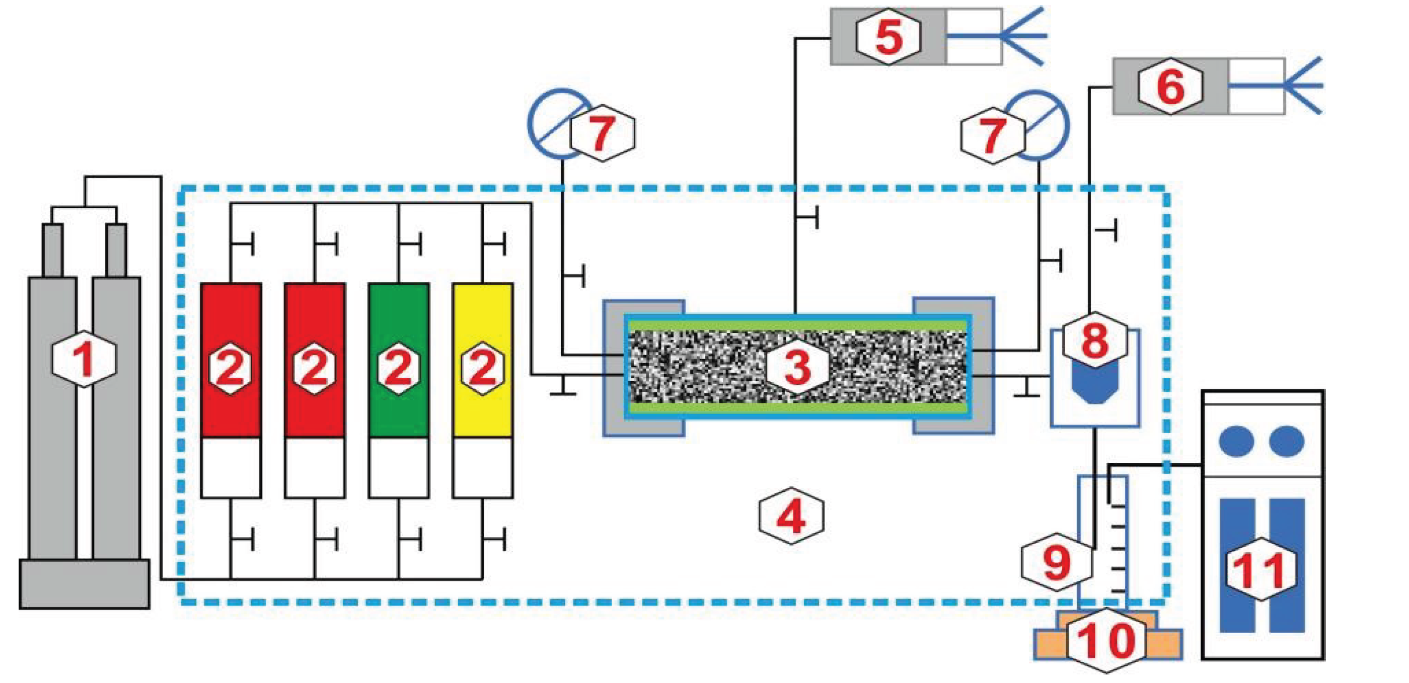
To investigate the huff and puff effect of CO2 miscible fracturing, the CO2 miscible fracturing huff and puff experiments are conducted by utilizing a core displacement device. The experimental device is schematically shown in Figure 3, and the experimental steps are:
①Evacuate and pressurize the core to achieve formation water saturation. Next, prepare the core by introducing bound water using a gas driving method. Determine the core’s irreducible water saturation through weight measurements before and after gas driving.
②Create a single-through fracture by splitting the core, thus mimicking the fracturing characteristics of the reservoir. Subsequently, load the core into the core holder and saturate it with dead oil.
③Displace the dead oil with live oil until the gas-oil ratio at the outlet matches that of the live oil, and then perform aging.
④Inject 0.1PV of the fracturing fluid additive at a low flow rate and formation temperature. Then, displace the oil continuously with CO2 until the pressure reaches 55 Mpa. Shut-in the well after closing the valve, and reopen it after the specified shut-in time. Gradually reduce the pressure by adjusting the back pressure valve. Throughout this process, record the oil and gas production to evaluate recovery efficiency.

3. Experimental Results and Analysis

3.1. Mechanism of Oil Production Increase

3.1.1. Interaction between CO2 And Crude Oil

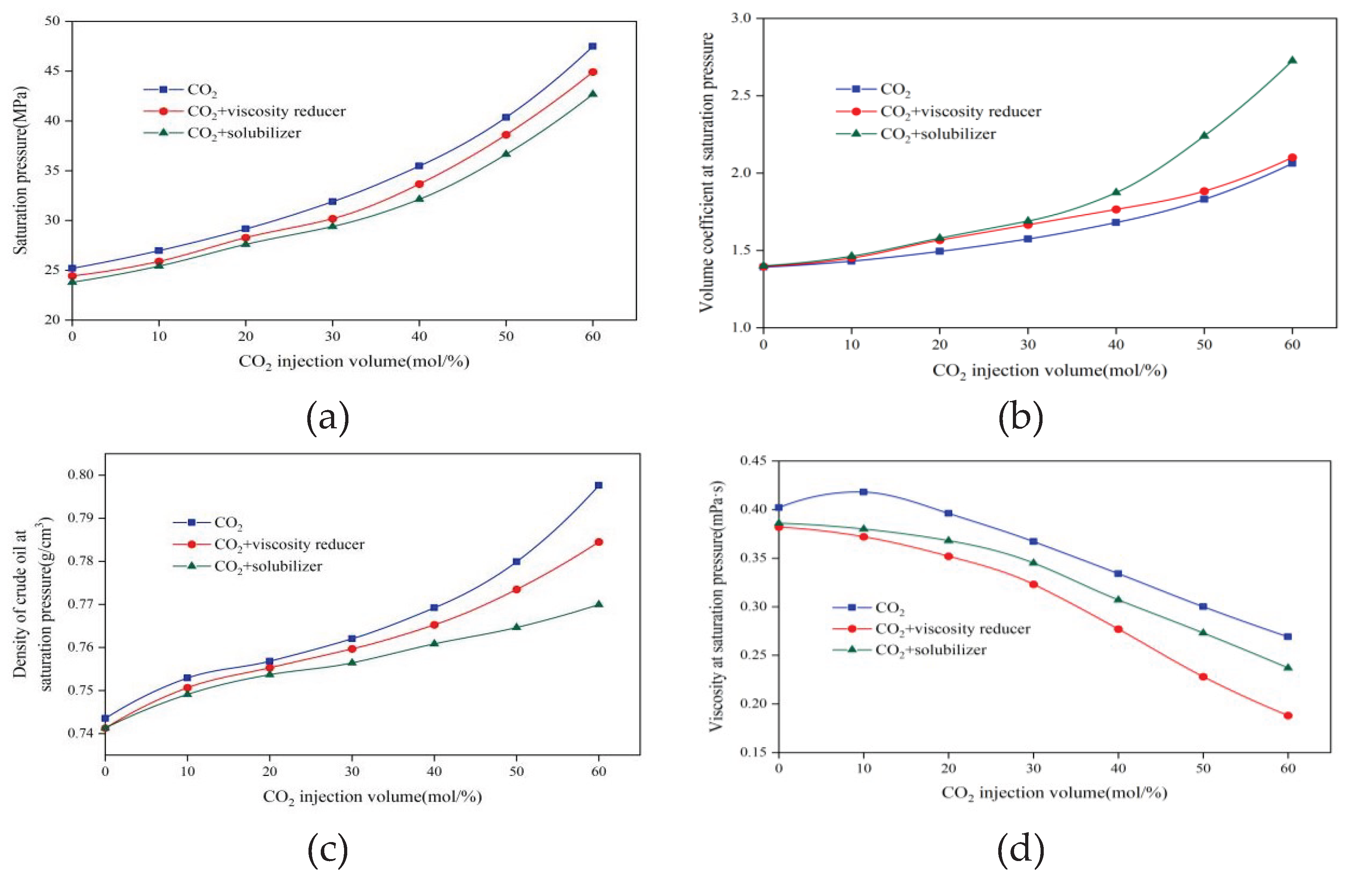
The experimental study investigates the impact of CO2 and CO2 miscible fracturing fluid on the properties of crude oil. The results are presented in Figure 4. One can conclude that the saturation pressure, volume coefficient, and density of crude oil increase with the increase of CO2 injection amount. Specifically, when the CO2 injection amount is from 0 to 60mol%, the saturation pressure increases from 25.2Mpa to 47.49Mpa, the volume coefficient increases from 1.3915 to 2.0630, and the crude oil density increases from 0.7435 g/cm3 to 0.7966g/cm3. Conversely, the viscosity of crude oil decreases as the injection volume increases, transitioning from 0.402mPa·s to 0.269mPa·s. It should be noted that since the density of CO2 is higher than that of crude oil under high saturation pressure. Consequently, the more CO2 dissolved in crude oil, the higher the density of crude oil will be [23]. The above results indicate that CO2 plays a pivotal role in expanding and reducing viscosity of crude oil, thereby facilitating its solubilization, expansion, and displacement.
Upon introducing a solubilizer or viscosity reducer and dissolving an equivalent amount of CO2, the volume coefficient of crude oil surpasses that of oil without additives. Simultaneously, the saturation pressure, density, and viscosity of the crude oil decrease. In addition, as the injection amount of CO2 increases, the corresponding increase or decrease in these properties becomes more pronounced. The results demonstrate that the additives effectively enhance CO2 dissolution in crude oil. This phenomenon leads to increased oil expansion, greater elastic energy, reduced viscosity, and improved fluidity, thereby making the crude oil easier to be extracted. Solubilizers exhibit more significant changes in saturation pressure, volume coefficient, and crude oil density compared to viscosity reducers, indicating that solubilizers have a better effect on crude oil and can produce more crude oil.

3.1.2. Minimum Miscibility Pressure

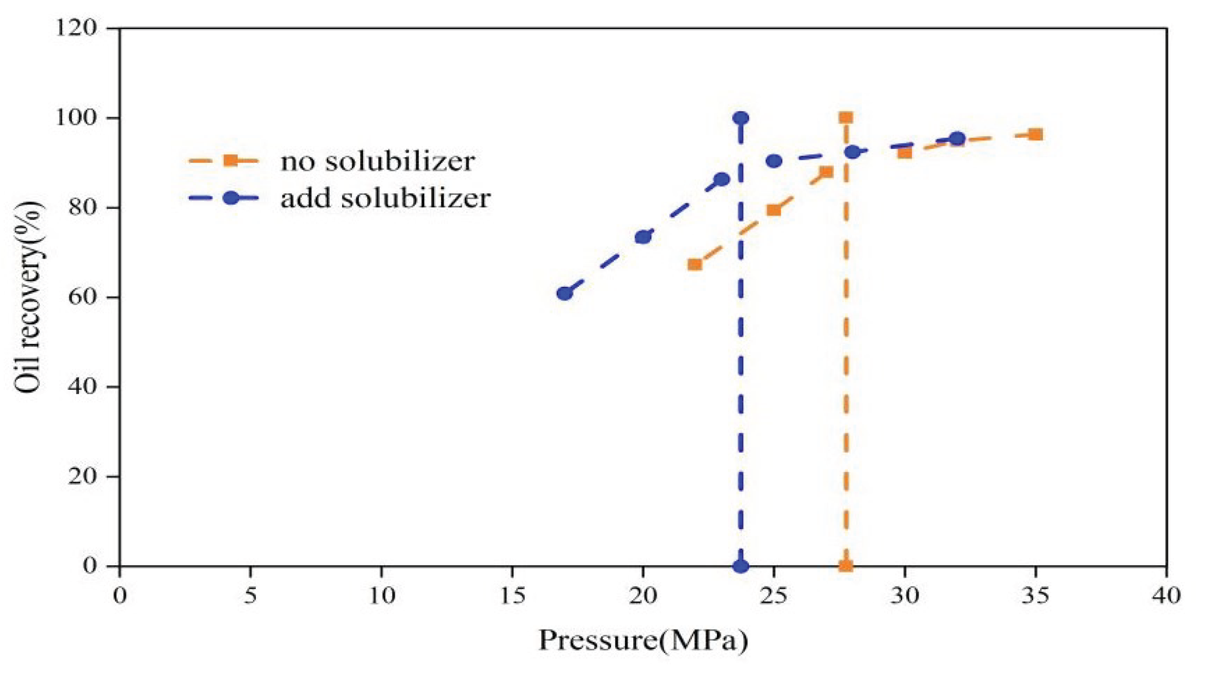
Crude oil and CO2 can achieve miscibility under the condition that the reservoir injection pressure surpasses the minimum miscibility pressure. This process results in a reduction of the surface tension of the miscible oil, thereby enhancing the efficiency of oil recovery. The minimum miscibility pressure experiment is conducted to explicit the miscibility conditions for CO2 miscible fracturing huff and puff. The results are organized in Figure 5. The minimum miscibility pressure for formation crude oil and CO2 in the absence of a solubilizer is 27.76 MPa. This indicates that miscibility can be attained by injecting CO2 under the formation pressure of the reservoir (33MPa). In contrast, the minimum miscibility pressure decreases to 23.73 MPa after injecting 0.1 PV solubilizer, representing a reduction of 14.52% compared to the previous value. This reduction can be attributed to the solubilizer’s ability to decrease the interfacial tension between CO2 and crude oil, thereby facilitating the dissolution of more CO2 into the crude oil.

3.2. Effect of Huff and Puff

3.2.1. Impact of Fracturing Fluid Additives

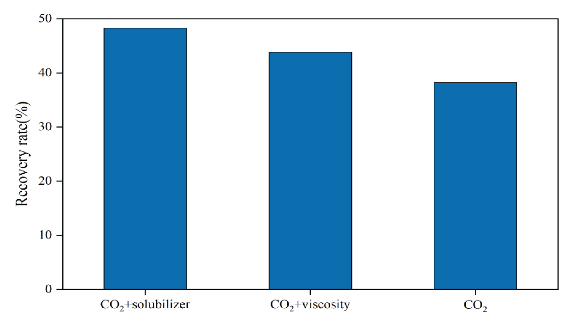
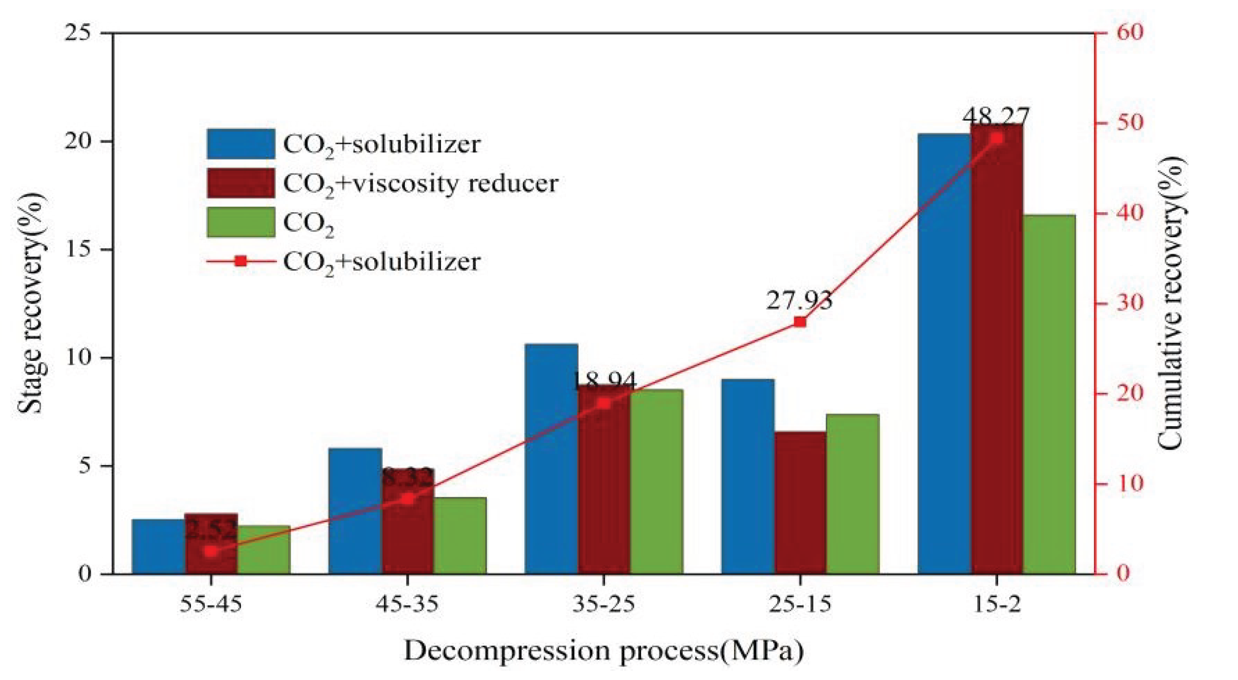
Huff and puff experiments involving CO2, CO2+solubilizer, and CO2+viscosity reducer are conducted on cores 2-1, 2-2, and 2-3, respectively. These experiments are conducted under identical well soaking durations of 12 hours. The results are arranged in Figure 6 and Figure 7. As can be seen from Figure 6, for cores exhibiting the same permeability level, the combination of CO2 and solubilizer yields the highest recovery efficiency, at 48.27%. The recovery efficiencies for the combinations of CO2 and viscosity reducer, and CO2 alone, are marginally lower, at 43.80% and 38.22%, respectively. Injecting solubilizer slugs can increase the recovery rate of huff and puff by 10.05% compared with CO2 huff and puff. That means the injection of solubilizer allows more CO2 to be dissolved in the crude oil, which expands the volume and reduces the viscosity of the crude oil, allowing more crude oil to be extracted under the swelling effect during extraction.
Figure 7 illustrates a positive correlation between the decrease in average pressure and the increase in stage recovery efficiency. Notably, a pressure range of 35-25 MPa yields a marginally higher stage recovery efficiency compared to the range of 25-15 MPa. This is because CO2 and crude oil have reached a miscible state at 35-25MPa and further pressure reduction will cause resistance due to large amounts of degassing, resulting in a slight reduction in the stage recovery efficiency at the 25-15MPa. However, continued pressure reduction causes the separated gas gathers to produce a gas-driving effect, thereby promoting the flow of crude oil.Consequently, the stage recovery efficiency escalates within the 15-2 MPa range.

3.2.2. Impact of Shut-in Time

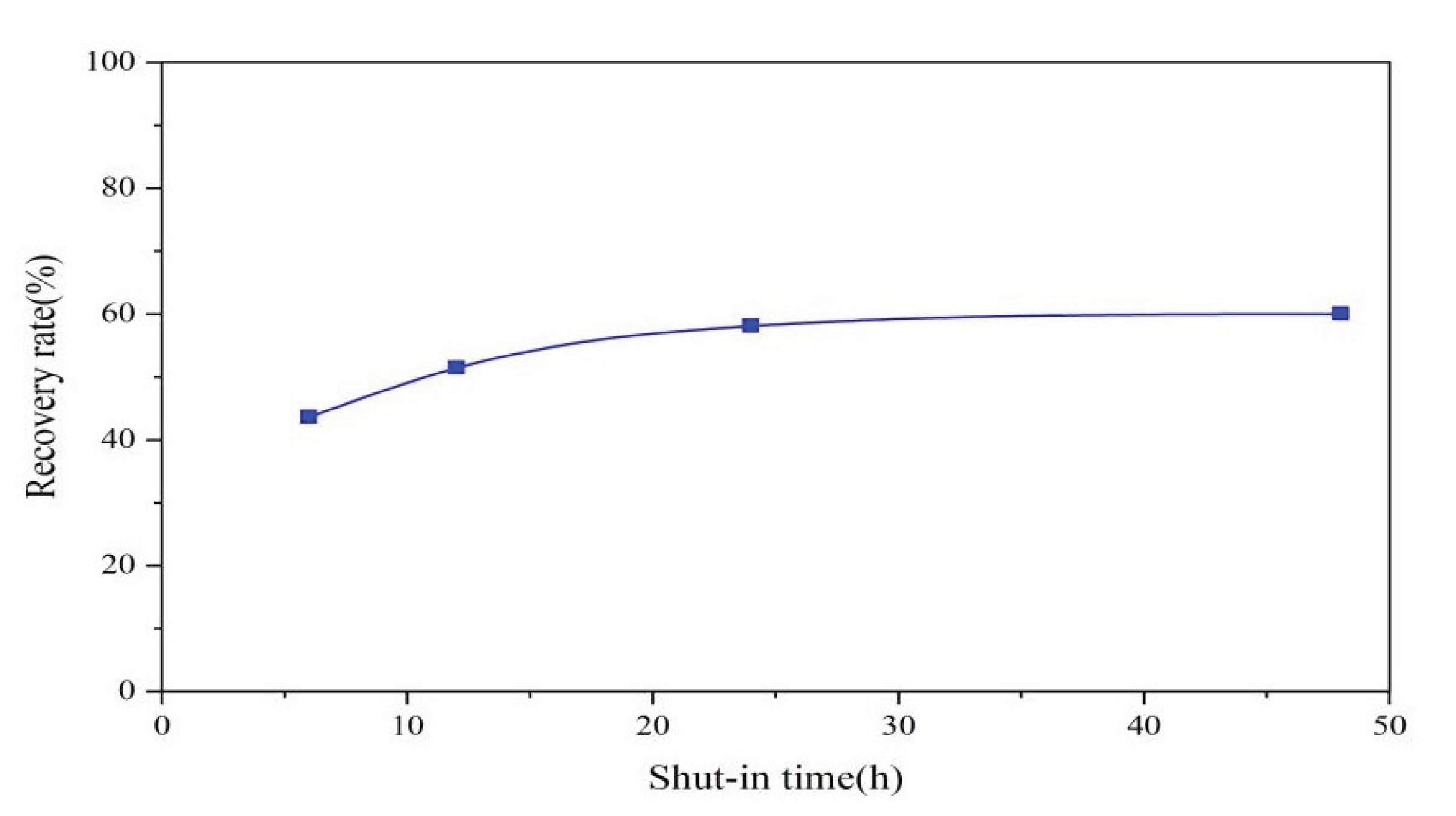
Cores 1-1, 1-2, 1-3, and 1-4 are adopted to carry out experiments on the huff and puff effect of CO2+solubilizer at varying shut-in times. As depicted in Figure 8, there is a positive correlation between the well shut-in time and the recovery efficiency for cores of identical permeability. However, beyond a well shut-in duration of 24 hours, the recovery efficiency plateaus, suggesting that the optimal well soaking time has been achieved.
Referring to Figure 9, it is known that the lower the blowout pressure, the more oil is produced, and the increase in huff and puff production is more obvious in the later stage of pressure drop. This phenomenon is because the crude oil produced in the initial stage mainly relies on the expansion effect caused by CO2 dissolved in the crude oil. While the pressure drops below the saturation pressure, the CO2 dissolved in the crude oil starts to separate from the oil, leading to the gas propelling the crude oil during the discharge process.

3.2.3. Impact of Permeability

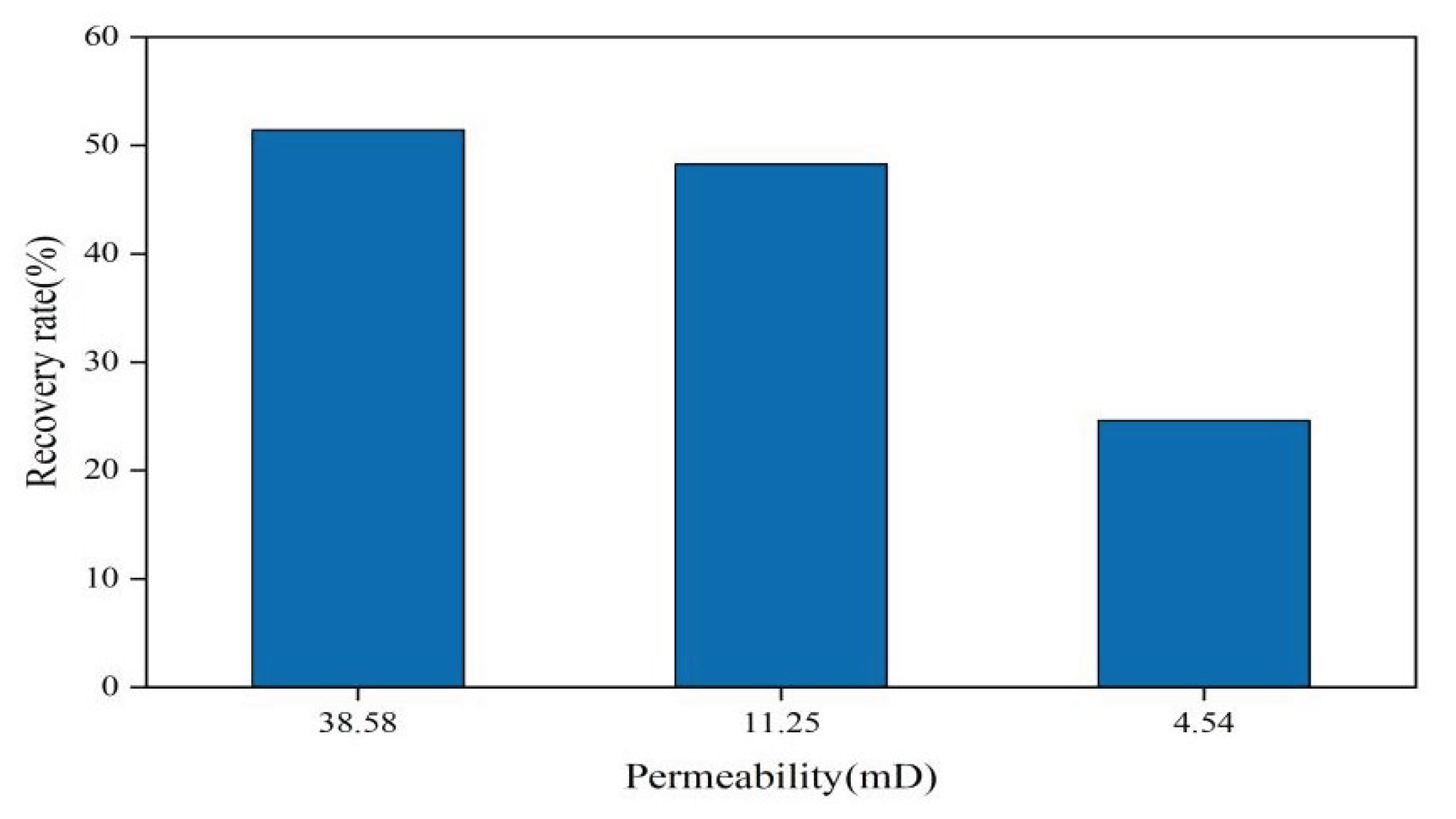
Cores with different permeabilities (No. 1-2, 2-2, and 3-1) were used to carry out experiments on the huff and puff effect of CO2+solubilizer under the same well shut-in time (12h). As depicted in Figure 10, a positive correlation is observed between the permeability and the recovery efficiency. The corresponding recovery efficiency results for the three cores are 51.43%, 48.27%, and 24.59%, respectively. The recovery rate of the high-permeability core is 26.83% higher than that of the low-permeability core.

3.2.4. Impact of Huff and Puff Patterns

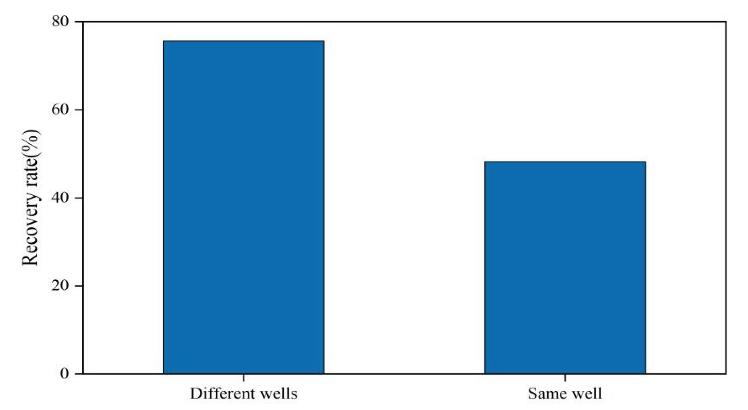
The previous experiments adopted the same-well huff and puff method. This method refers to injecting CO2 and additives from the outlet end, and performing depressurization mining from the outlet end after shut in the well for a certain time. To examine the impact of the huff and puff method on recovery efficiency, cores No. 2-4 are employed to conduct different well huff and puff experiments. This alternative method is to injecting CO2 and additives from the outlet end, then mining from the inlet end after shut in the well for a certain time. The additive used is a solubilizer, and the shut-in time is 12 h. The experimental results are plotted in Figure 11.
The results indicate that the huff and puff method significantly impacts the recovery efficiency, and the different-well method shows a better performance. Compared with the 48.27 % recovery efficiency of the same-well huff and puff method, the different-well method exhibited an increase of 27.39 %. The dissolution rate of injected CO2 and additives mainly depends on the diffusion rate of CO2 in crude oil, which in turn is influenced by the concentration difference and the contact extent between CO2 with crude oil. When using the injection well for production, a substantial quantity of CO2 returns first when the pressure drops as the CO2 accumulates at the bottom. Consequently, the originally saturated crude oil becomes difficult to produce due to large amounts of degassing. However, when producing from a production well, the injected CO2 can continuously drive the oil from the injection well to the production well. Moreover, benefiting from the dissolution and expansion capabilities of CO2, the CO2 around the injection well can serve the dual role of pressure maintenance and secondary displacement, thereby significantly increasing crude oil production.

4. Conclusions

The process of injecting CO2 into crude oil to achieve a miscible state results in the expansion of the crude oil volume, a reduction in viscosity, and an increase in elastic energy, all of which contribute significantly to enhancing the efficiency of crude oil recovery. This study clarified the oil-increasing mechanism and huff and puff effect of CO2 miscible fracturing fluid through a series of experiments. The experimental results proved that the introduction of fracturing fluid additives can make CO2 more easily dissolved in crude oil, and the solubilizer is more effective than the viscosity reducer. The solubilizer can increase the oil recovery efficiency by an additional 10.05% and reduce the minimum miscibility pressure of CO2 and crude oil from 27.76MPa to 23.73MPa.The study also reveals that factors such as shut-in time, permeability, and the method of huff and puff significantly influence the huff and puff effect. Specifically,the recovery efficiency is proportional to the well shut-in time but there is the most reasonable time of 24 h; the recovery rate of high-permeability cores is 26.83% higher than that of low-permeability cores; and the recovery efficiency of different-well stimulation is 27.39% higher than that of the same-well stimulation. These findings offer valuable insights for the practical application of the CO2 miscible fracturing huff and puff method in reservoirs.

Acknowledgments

This work was financially supported by “The Open Foundation of Shaanxi Key Laboratory of Carbon Dioxide Sequestration and Enhanced Oil Recovery”. The authors would like to thank the editor and the reviewers of this paper for their valuable comments that helped improve the quality of the paper.

Conflicts of Interest

The authors declare that they have no known competing financial interests or personal relationship that could have appeared to influence the work reported in this paper.

References

  1. Yuejun Zhao, Guangjuan Fan, Kaoping Song, Yilin Li, Hao Chen, et al. The experimental research for reducing the minimum miscibility pressure of carbon dioxide miscible flooding. Renewable and Sustainable Energy Reviews 2021, 145, 111091. [CrossRef]
  2. N. Li, L. S. Cheng, Q. Li, C. Li, W. Sun. Phase change characteristics during carbon dioxide flooding. Energy Sources, Part A: Recovery, Utilization, and Environmental Effects 2012, 34(15), 1400-1406. [CrossRef]
  3. Seyyedi Mojtaba, Sohrabi Mehran. Assessing the feasibility of improving the performance of CO2 and CO2–WAG injection scenarios by CWI. Industrial & Engineering Chemistry Research 2018, 57(34), 11617-11624. [CrossRef]
  4. R. Miscible gas displacement of multicomponent oils. SPE J. 1996, 1(01), 39–50. [CrossRef]
  5. Angang Zhang, Zifei Fan, Lun Zhao. An investigation on phase behaviors and displacement mechanisms of gas injection in gas condensate reservoir. Fuel 2020, 268, 117373. [CrossRef]
  6. Tengfei Wang, Liangliang Wang, Xingbang Meng, Yi Chen, Wei Song, Chengdong Yuan. Key parameters and dominant EOR mechanism of CO2 miscible flooding applied in low-permeability oil reservoirs. Geoenergy Science and Engineering 2023, 225, 211724. [CrossRef]
  7. Maryam Mohdsaeed H., I. Abdulla, Shaligram Pokharel. Analytical models for predicting oil recovery from immiscible CO2 injection: A literature review. Journal of Petroleum Science and Engineering 2022, 219, 111131. [Google Scholar] [CrossRef]
  8. Shokufe Afzali, Nima Rezaei, Sohrab Zendehboudi. A comprehensive review on enhanced oil recovery by water alternating gas(WAG) injection. Fuel 2018, 227, 218–246. [CrossRef]
  9. Liping He, Pingping Shen, Xinwei Liao, QiChao Gao, Chengsheng Wang, Fangfang Li. Study on CO2 EOR and its geological sequestration potential in oil field around Yulin city. Journal of Petroleum Science and Engineering 2015, 134, 199–204. [CrossRef]
  10. Mohamed Almobarak, Zangyuan Wu, Daiyu Zhou, Kun Fan, Yongbing Liu, Quan Xie. A review of chemical-assisted minimum miscibility pressure reduction in CO2 injection for enhanced oil recovery. Petroleum 2021, 7, 245–253. [CrossRef]
  11. Hao Chen, Bowen Li, Xiansong Zhang, Quan Wang, Xiaoqiang Wang, Shenglai Yang. Effect of gas contamination and well depth on pressure interval of CO2 near miscible flooding, Journal of Petroleum Science and Engineering 2019, 176, 43–50. [CrossRef]
  12. Ramin Moghadasi, Alireza Rostami, Abdolhossein Hemmati-Sarapardeh. Enhanced oil recovery using CO2. Fundamentals of Enhanced Oil and Gas Recovery from Conventional and Unconventional Reservoirs 2018, 61–99. [CrossRef]
  13. Hamid, R. Lashgari, Alexander Sun, Tongwei Zhang, Gary A. Pope, Larry W. Lake. Evaluation of carbon dioxide storage and miscible gas EOR in shale oil reservoirs. Fuel 2019, 241, 1223–1235. [Google Scholar] [CrossRef]
  14. Cheng Chen, Matthew Balhoff, Kishore K. Mohanty. Effect of reservoir heterogeneity on primary recovery and CO2 huff ‘n’ puff recovery in shale-oil reservoirs. SPE Reservoir Evaluation & Engineering 2014, 17(3), 404-413. [CrossRef]
  15. Zeya Li, Yongan Gu. Soaking effect on miscible CO2 flooding in a tight sandstone formation. Fuel 2014, 134, 659–668. [CrossRef]
  16. Yuejun Zhao, Guangjuan Fan, Yilin Li, Xiaodan Zhang, Hao Chen, He Sun. Research for reducing minimum miscible pressure of crude oil and carbon dioxide and miscible flooding experiment by injecting critic acid isopentyl ester. Arabian Journal of Chemistry 2020, 13(12), 9207–9215. [CrossRef]
  17. He Liu, Feng Wang, Jian Zhang, Siwei Meng, Yongwei Duan. Fracturing with carbon dioxide: Application status and development trend. Petroleum exploration and development 2014, 41(4), 513-519. [CrossRef]
  18. Zhengguo He, Shouceng Tian, Gensheng Li, Haizhu Wang, Zhongzhu Shen, Zhengming Xu. The pressurization effect of jet fracturing using supercritical carbon dioxide. Journal of natural gas science and engineering 2015, 27(2), 842–851. [CrossRef]
  19. Narendra Kumar, Marcio Augusto Sampaio, Keka Ojha, Hussein Hoteit. Ajay Mandal. Fundamental aspects, mechanisms and emerging possibilities of CO2 miscible flooding in enhanced oil recovery: A review. Fuel 2022, 330, 125633. [CrossRef]
  20. Luis M., C. Pereira, Antonin Chapoy, Rod Burgass, Bahman Tohidi. Measurement and modelling of high pressure density and interfacial tension of (gas + n-alkane) binary mixtures. The Journal of Chemical Thermodynamics 2016, 97, 55–69. [Google Scholar] [CrossRef]
  21. Mingyong Du, Xin Sun, Caili Dai, Hao Li, Tao Wang, Zhongliang Xu, Mingwei Zhao, Baoshan Guan, Ping Liu. Laboratory experiment on a toluene - polydimethyl silicone thickened supercritical carbon dioxide fracturing fluid. Journal of Petroleum Science and Engineering 2018, 166, 369–374. [CrossRef]
  22. Houjian Gong, Xuejin Qin, Shengxiang Shang, Chaofan Zhu, Long Xu, Qian San, Yajun Li, Mingzhe Dong. Enhanced shale oil recovery by the huff and puff method using CO2 and cosolvent mixed fluids. Energy & Fuels 2020, 34(2), 1438-1446. [CrossRef]
  23. Su Yuliang, Wang Chenwei, Li Lei, Hou Zhengxiao, Fan Liyao, Chen Zheng. Behavior of CO2 pre-fracturing fluid in tight reservoir. Science Technology and Engineering 2021, 21(8), 3076-3081.
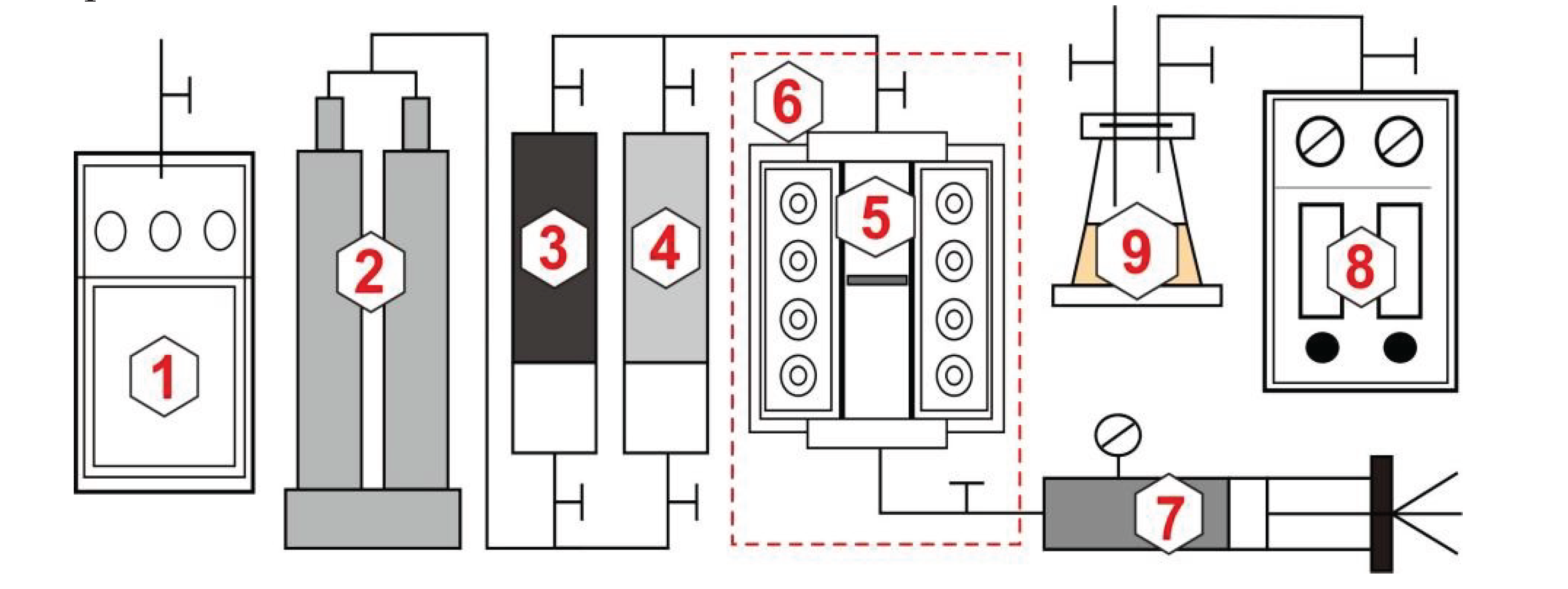
Figure 1. Schematic diagram of the PVT experimental device. 1) Chromatograph; 2)ISCO pump; 3)Oil; 4)CO2; 5)PVT visualization tube; 6)Temperate box; 7)High-pressure pump; 8)Gas meter; 9)Gas-liquid separator.
Preprints 101167 g001
Figure 2. Schematic diagram of the minimum miscibility pressure experimental device. 1)ISCO pump; 2)Live oil; 3)Dead oil; 4)CO2; 5)Slim tube; 6)Back pressure valve; 7)Gas-liquid separator; 8)Gas meter.
Preprints 101167 g002
Figure 3. Diagram of CO2 miscible throughput experimental device. 1)ISCO pump; 2)Live oil/dead oil/formation water/CO2; 3)Core holder; 4)Constant temperature oven; 5)Surrounding-pressure pump; 6)Back-pressure pump; 7) Pressure sensor; 8) Back-pressure valve; 9) Gas-liquid separator; 10) Electronic balance; 11) Gas meter.
Preprints 101167 g003
Figure 4. (a) The relationship between saturation pressure and CO2 injection amount. Under saturation pressure, the changes in crude oil’s (b) volume coefficient, (c) density, and (d) viscosity concerning the injection amount of CO2.
Preprints 101167 g004
Figure 5. Results of minimum miscibility pressure experiment between crude oil and CO2.
Preprints 101167 g005
Figure 6. Recovery efficiency results of adding different additives.
Preprints 101167 g006
Figure 7. Results of stage recovery efficiency of different additives in decompression process.
Preprints 101167 g007
Figure 8. Relationship between huff and puff recovery efficiency and well shut-in time.
Preprints 101167 g008
Figure 9. Results of huff and puff efficiency under different discharge pressures.
Preprints 101167 g009
Figure 10. Huff and puff efficiency of cores with different permeabilities.
Preprints 101167 g010
Figure 11. Effect of huff and puff method on recovery efficiency.
Preprints 101167 g011
Table 1. Core basic parameters and corresponding experimental settings.
Core Length(cm) Diameter(cm) Permeability(mD) Porosity(%) Injection medium Shut-in time Huff and puff mode
1-1 9.454 2.523 39.42 19.72 CO2+solubilizer 6 Same well
1-2 9.835 2.525 38.58 19.27 12
1-3 9.637 2.521 39.15 19.31 24
1-4 9.646 2.523 38.97 18.96 48
2-1 9.832 2.520 11.85 17.02 CO2 12 Same well
2-2 9.994 2.521 11.25 17.25 CO2+solubilizer
2-3 9.705 2.522 11.48 17.31
2-4 9.924 2.523 12.07 17.59 Different well
3-1 9.841 2.532 4.54 12.72 Same well
Disclaimer/Publisher’s Note: The statements, opinions and data contained in all publications are solely those of the individual author(s) and contributor(s) and not of MDPI and/or the editor(s). MDPI and/or the editor(s) disclaim responsibility for any injury to people or property resulting from any ideas, methods, instructions or products referred to in the content.
Copyright: This open access article is published under a Creative Commons CC BY 4.0 license, which permit the free download, distribution, and reuse, provided that the author and preprint are cited in any reuse.
Prerpints.org logo

Preprints.org is a free preprint server supported by MDPI in Basel, Switzerland.

Subscribe

© 2024 MDPI (Basel, Switzerland) unless otherwise stated