1. Introduction
In recent years, the global escalating environmental challenges have intensified the exploration of using TiO
2 photocatalysts as a promising solution. These materials have predominantly found application in the remediation of pollutants in both water and air due to their versatility [
1]. While powdered catalysts have demonstrated efficacy, they are not without limitations, particularly concerning challenges in stirring and subsequent separation processes [
2]. In contrast, thin-film catalysts have emerged as a viable alternative, overcoming these drawbacks with multiple potential applications.
Various studies have investigated the preparation of thin TiO
2 coatings utilizing diverse synthesis techniques such as spray-coating, sol–gel, and chemical vapor deposition (CVD) [
3,
4,
5]. The inherent advantage of thin TiO
2 coatings lies in their seamless integration onto substrates with irregular shapes and expansive surface areas. Recent studies have underscored the pivotal role played by morphology and crystalline structure in influencing the photocatalytic activity of these coatings [
6,
7].
Despite the substantial progress in this field, there remains a noteworthy gap in the literature regarding the utilization of hydroxyapatite as a substrate for TiO
2 thin films. While studies have explored various substrates such as quartz, glass, silicon, and aluminum [
8], the potential of hydroxyapatite has not been extensively investigated. Previous research examined hydroxyapatite as a photocatalyst in the aqueous phase [
9], albeit limited by its high band-gap energy, restricting its use to UV irradiation.
In a noteworthy departure from conventional studies, recent investigations have demonstrated the exceptional photocatalytic oxidation activity of hydroxyapatite–titanium (HAp/TiO
2) composite materials [
10]. The innovation lies in harnessing the remarkable co-absorbent properties of hydroxyapatite, resulting in a substantial enhancement in photocatalytic activity. Furthermore, the environmentally friendly nature of hydroxyapatite as a calcium compound adds an extra dimension to its appeal. HAp/TiO
2 composites offer unique advantages for TiO
2 coatings, particularly in biomedical and photocatalytic applications where enhanced biocompatibility and performance are desired. While they may involve higher initial costs and more complex fabrication processes than pure titanium substrates, the benefits they provide justify their use in specific applications where their properties are advantageous.
In the current study, we present a novel approach synthesizing TiO2 thin films on hydroxyapatite (HAp) substrates. Our methodology involves microwave-assisted synthesis to produce hydroxyapatite flakes and chemical vapor deposition using metal–organic precursors to achieve the desired coatings. This multifaceted synthesis strategy aims to capitalize on the unique properties of hydroxyapatite and TiO2, offering a potential breakthrough in the development of advanced photocatalytic materials with enhanced efficiency and environmental sustainability. The goal of this study is to comprehensively analyze the morphological and structural properties of this hydroxyapatite–titanium (HAp/Ti) composite material. Specifically, we aim to investigate crystalline hydroxyapatite flakes as an efficient substrate for titanium dioxide coatings. Furthermore, we suggest innovative uses for the HAp/Ti composite material, thereby contributing to the development of future research in this field.
2. Materials and Methods
Materials: Calcium nitrate [Ca(NO3)2], glutamic acid [C5H9NO4], potassium phosphate [K2HPO4], and potassium hydroxide [KOH]. Distilled water was used in all synthesis steps.
Calcium nitrate [Ca(NO
3)
2] (1.16 g) and glutamic acid [C
5H
9NO
4] (4.35 g) were mixed in 300 ml of distilled water, to which glutamic acid was slowly added. The solution was stirred for 55 min at 70 °C. Meanwhile, potassium phosphate [K
2HPO
4] (1.12 g) and potassium hydroxide [KOH] (0.76 g) were mixed in 100 ml of distilled water. The solution was stirred for 15 min at 85 °C. Then, both solutions were mixed dropwise and stirred for 20 min at 85 °C. Finally, 20 glasses with 20 ml of solution were placed in the microwave oven (Monowave). The microwave conditions were a 200 °C temperature, a 10 min heating ramp, a 45 min reaction time, and a 55 min cooling time [
11].
Once the process in the microwave oven was completed, the solid phase was filtered and washed with deionized water. The samples were placed in a desiccator at room temperature to obtain the hydroxyapatite flakes (HAp). The next step was to deposit the TiO
2 thin films on the HAp flakes using the metal–organic chemical vapor deposition technique (MOCVD) [
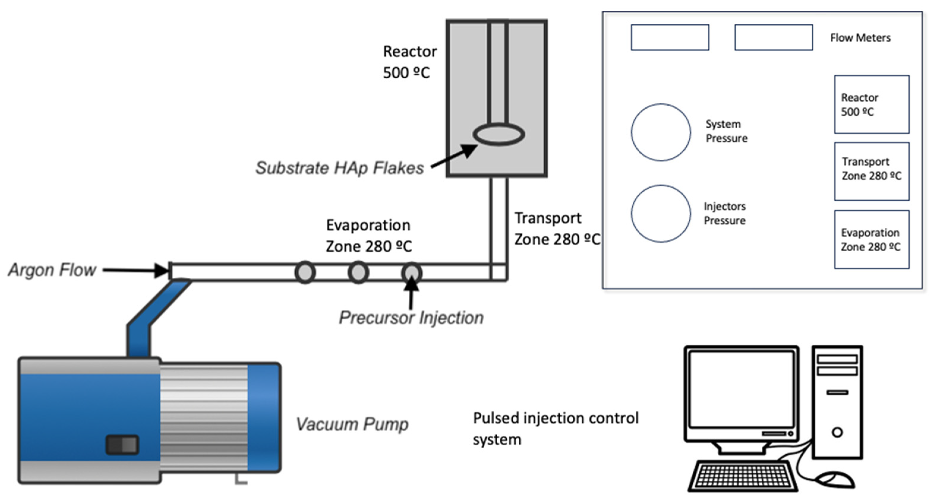
12]. For this, 10 ml of acetone mixed with 20 ml of titanium isopropoxide was used as a precursor. The synthesis parameters are shown in
Table 1, and the schematic diagram of the synthesis process is shown in
Figure 1.
2.1. Phase Composition: X-ray Diffraction (XRD)
X-ray powder diffraction was used to identify the crystalline phases contained in all the samples. Wide-angle X-ray experiments were carried out using a Rigaku Mini Flex diffractometer and Cu
radiation (λ = 1.5406Å, an accelerating voltage of 40 kV, and a current of 30 mA. Diffractograms were recorded with a Solid-State D/teX-ULTRA Detector from 5 to 80 º on a 2θ scale and a rate of 10 º per minute. The spectrum analysis software MDI Jade V 5.0.37 was used [
11].
2.2. Morphology and Microstructure: Scanning Electron Microscopy (SEM)
Morphological, topological, and microstructural analyses of all the samples were carried out using a JEOL JXA-8530F Scanning Electron Microscope. The analysis was performed using a 20 kV electron acceleration voltage, and the secondary electrons formed the images. All the samples were placed on a stainless-steel plate with a separation of 5 mm, pasted with silver paint, and covered with a gold thin film through sputtering to avoid the electrostatic charge accumulation [
11].
2.3. Elemental Composition: Dispersive-Energy Spectroscopy (EDS)
To obtain the elemental composition of HAp/ TiO
2 powders, an Electronic Microprobe for Microanalysis (EPMA) JXA - 8530F was used. The operation conditions were a voltage of 10 kV and a current of 0.10 nA. A small tablet was made from each sample, and then each tablet was coated with a graphite thin film [
11].
3. Results and Discussion
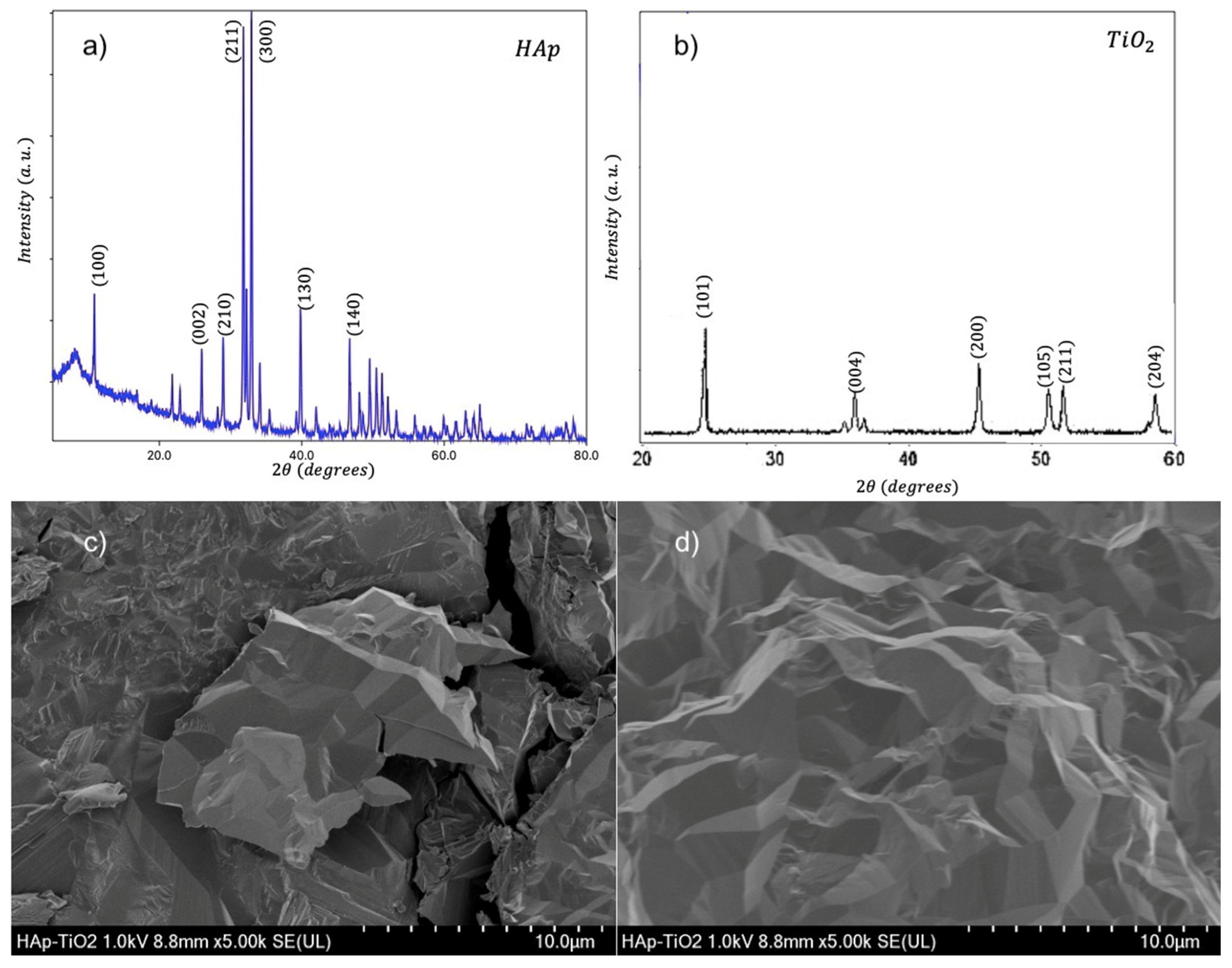
We present diffractograms and micrographs of both sides of the flakes (
Figure 2). XRD (X-Ray diffraction) studies show the crystal structure corresponding to hydroxyapatite according to the Powder Diffraction File (PDF) # 01-084-1998 (
Figure 2a). The observed Bragg reflections indicate a preferential direction of growth in the (100) plane due to the use of glutamic acid during the synthesis process [
12]. On the other hand (
Figure 2b), the diffraction pattern corresponding to the TiO
2 coating is shown, where the indexed reflections correspond to the anatase phase of TiO
2 and the pattern shows low-intensity and well-defined peaks; however, background noise is observed. Additionally, SEM (scanning electron microscopy) micrographs of uncoated HAp flakes (
Figure 2c) and TiO
2-coated HAp flakes are shown (
Figure 2d). The HAp side shows a morphology of agglomerated plaques. This morphology is characteristic of the hydroxyapatite plaques reported in previous studies [
13]. The TiO
2 coating (
Figure 1d) shows a uniform film free of cracks, where the formation of nanostructures with well-defined faces is observed, indicating step-by-step growth. This growth occurs due to the MOCVD synthesis process using a metal–organic precursor [
14].
The flakes show a compact structure; however, they can easily be divided into hydroxyapatite rods. As is well-established, the crystalline structure of hydroxyapatite is formed through the assembly of Ca type I (trigonal prisms), Ca type II (pentagonal dipyramids), phosphate groups (tetrahedra), and OH groups. The interaction mechanism of glutamic acid with this structure enables the incorporation with type I calcium, thereby inhibiting growth in the c-direction of the structure. This inhibition promotes growth in the a and b directions, consequently resulting in a plate-like morphology.
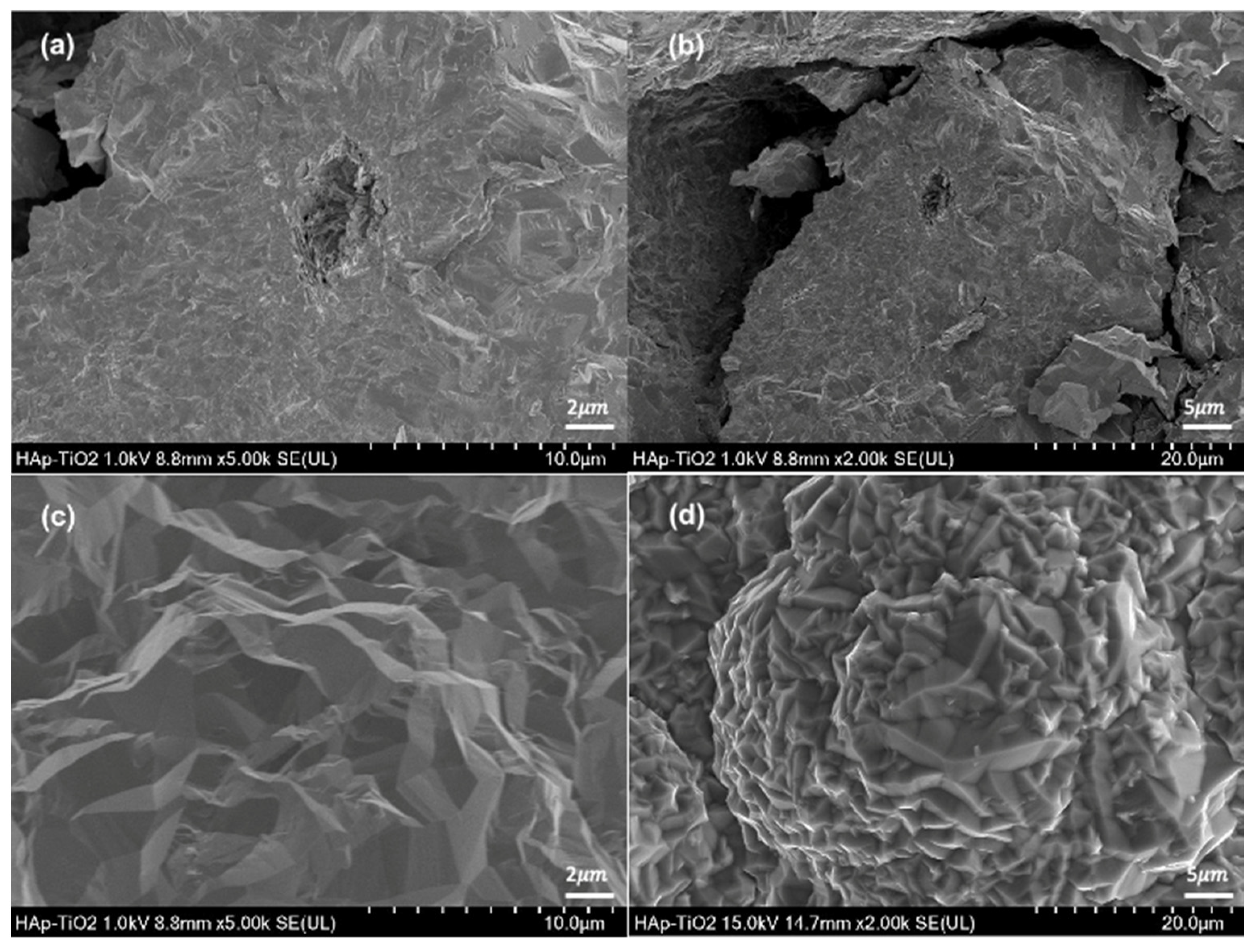
Micrographs of the hydroxyapatite flakes and TiO2 thin films are shown (
Figure 3). The hydroxyapatite flakes show a homogeneous morphology with some reliefs at magnifications of 5000x (
Figure 3a); in addition, agglomerated plates with dimensions of 10 μm can be observed (
Figure 3b) at 2000x.
Likewise, the observed plates are composed of agglomerated rods. This morphology is characteristic of the hydroxyapatite obtained through hydrothermal methods [
15]. Hydroxyapatite flakes are obtained depending on the amount of glutamic acid used in the synthesis process and the filtering of the sample when leaving the microwave oven. Micrographs of the TiO
2 thin film at 5000x magnification (
Figure 3c) and 2000x magnification (
Figure 3d) are also shown. Both micrographs show the typical morphology of TiO
2 films obtained through MOCVD [
16]. The MOCVD process allows a coating on the upper face of the hydroxyapatite flake, and a structure of densely packed crystals with a faceted prism appearance are observed. At the lowest magnification, the crystals can be observed forming a flower-like morphology. This might be due to the rearrangement of the deposited crystals. After the initial deposition of the crystals, the rearrangement process begins with their nucleation. This involves the formation of small groups of crystals from the initial material, causing flower-like growth.
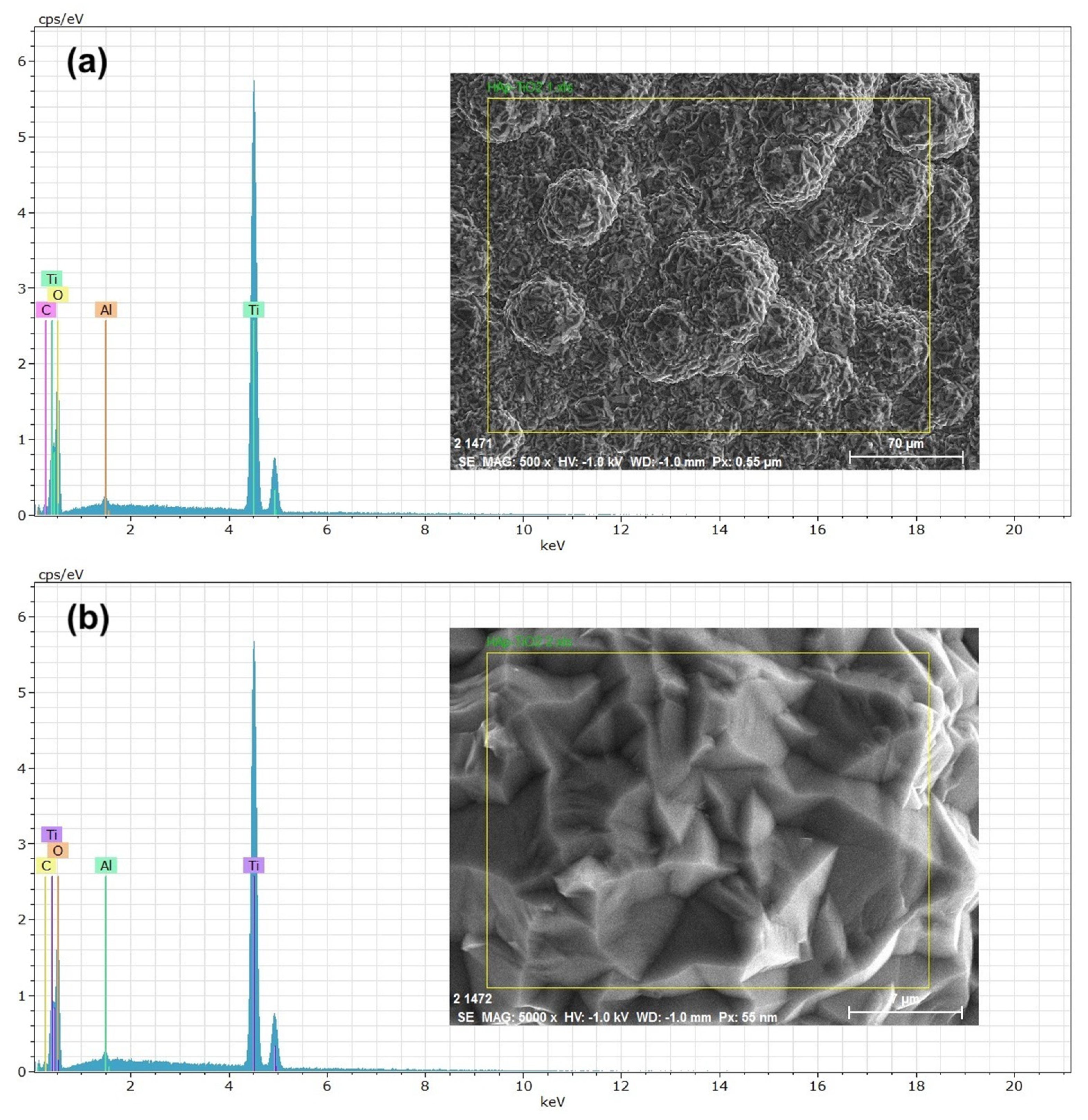
EDS (energy-dispersive spectroscopy) elemental composition analyses were performed on the TiO
2 thin films (
Figure 4). The results shown at 500x (
Figure 4a) and 5000x (
Figure 4b) magnifications reveal that the peaks predominantly correspond to Ti (titanium) and O (oxygen) and that the presence of aluminum in the spectra is due to the sample holder used during the analysis. High, sharp peaks indicate that the thin films are of high purity and were successfully deposited on the substrate. The presence of Ca and P is not visible in the spectra because only the TiO2-coated part was analyzed. The atomic percentage of Ti in the sample was 30.89 % on average. The EDS results agree with the previous DRX and SEM studies, demonstrating that the elemental composition of the thin films allowed us to determine the chemical composition of the samples. Numerous studies have considered this method for composition analysis [
17]. In the EDS study, the accelerating voltage of the electron beam had a significant influence on the obtained results [
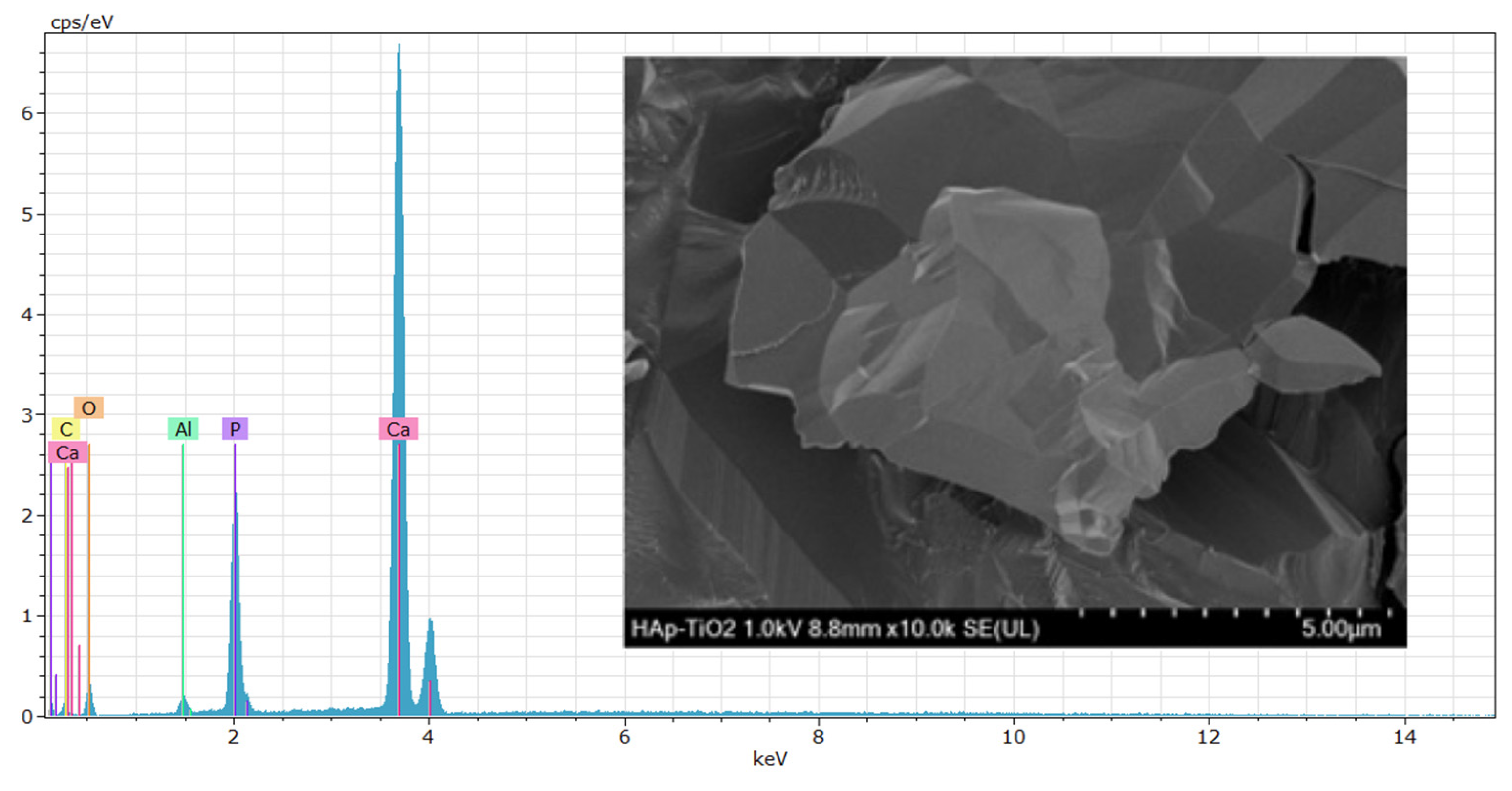
18]. In
Figure 5, the EDS spectrum for the hydroxyapatite flakes is depicted, revealing the presence of calcium and phosphorus with a Ca/P ratio of 1.69. Additionally, both spectra exhibit a trace amount of aluminum, measured at 0.56 wt.%. This aluminum presence is likely attributed to contamination from impurities in the gases utilized during the MOCVD synthesis process.
4. Conclusions
We achieved the successful synthesis of hydroxyapatite flakes through the utilization of the microwave-assisted hydrothermal method. Notably, our investigation brought to light the significant impact of glutamic acid on the morphology of hydroxyapatite flakes, providing valuable insights into their structure. Furthermore, we extended our study to include the synthesis of titanium dioxide (TiO2) thin films utilizing hydroxyapatite flakes as a substrate. The X-ray diffraction (XRD) analysis revealed distinct diffraction peaks corresponding to the presence of hydroxyapatite on one side of the flake and TiO2 in the anatase phase on the opposite side. This dual-phase formation is remarkable, showcasing the versatility of the hydroxyapatite substrate. Scanning electron microscopy (SEM) studies offer a detailed glimpse into the morphology of TiO2 thin films, showcasing a homogeneous arrangement of faceted crystals with a prismatic appearance. The uniformity observed in this morphology enhances the potential applications of TiO2 coating. Elemental analysis through energy-dispersive X-ray spectroscopy (EDS) has further supported our findings, elucidating the elemental composition of the coatings. This underscores the successful integration of hydroxyapatite flakes in TiO2 thin films. Our study lays the groundwork for future investigations, suggesting that we should continue exploring the photocatalytic properties of the composite material obtained (HAp/TiO2). Additionally, these compounds have a potential application in biomedicine as a biocompatible material in tissue regeneration.
The versatile coating technique employed, metal–organic chemical vapor deposition (MOCVD), emerges as a powerful tool, providing control over the thickness and structure of TiO2 thin films.
Author Contributions
Conceptualization Néstor Méndez-Lozano; methodology Néstor Méndez-Lozano; software, investigation, Néstor Méndez-Lozano; writing—original draft preparation, Néstor Méndez-Lozano.; writing—review and editing, Eduardo E. Pérez-Ramírez.; supervision, Miguel de la Luz-Asunción; project administration, Eduardo E. Pérez-Ramírez.
Funding
This research received no external funding
Institutional Review Board Statement
Not applicable.
Informed Consent Statement
Not applicable.
Data Availability Statement
Data available on request from the authors.
Conflicts of Interest
The authors declare no conflict of interest.
References
- Yu, J., & Zhao, X. Effect of substrates on the photocatalytic activity of nanometer TiO2 thin films. Materials Research Bulletin 2000, 35(8), 1293-1301. [CrossRef]
- Franz, S., Falletta, E., Arab, H., Murgolo, S., Bestetti, M., & Mascolo, G. Degradation of carbamazepine by photo (electro) catalysis on nanostructured TiO2 meshes: Transformation products and reaction pathways. Catalysts 2020, 10(2), 169. [CrossRef]
- Han, Z., Chang, V. W., Zhang, L., Tse, M. S., Tan, O. K., & Hildemann, L. M. Preparation of TiO2-coated polyester fiber filter by spray-coating and its photocatalytic degradation of gaseous formaldehyde. Aerosol and Air Quality Research 2012, 12(6), 1327-1335. [CrossRef]
- Cotolan, N., Rak, M., Bele, M., Cör, A., Muresan, L. M., & Milošev, I. Sol-gel synthesis, characterization, and properties of TiO2 and Ag-TiO2 coatings on titanium substrate. Surface and Coatings Technology 2016, 307, 790-799. [CrossRef]
- Lee, H., Song, M. Y., Jurng, J., & Park, Y. K. The synthesis and coating process of TiO2 nanoparticles using CVD process. Powder technology 2011, 214 (1), 64-68. [CrossRef]
- Komaraiah, D., Radha, E., Sivakumar, J., Reddy, M. R., & Sayanna, R. Photoluminescence and photocatalytic activity of spin coated Ag+ doped anatase TiO2 thin films. Optical Materials 2020, 108, 110401. [CrossRef]
- Dundar, I., Krichevskaya, M., Katerski, A., & Acik, I. O. TiO2 thin films by ultrasonic spray pyrolysis as photocatalytic material for air purification. Royal Society open science 2019, 6(2), 181578. [CrossRef]
- Latif, N. T., & Rzaij, J. M. Concentration Effect of Mixed SnO2-ZnO on TiO2 Optical Properties Thin Films prepared by Chemical Spray Pyrolysis Technique. J. Univ. Anbar pure Sci 2020, 14(1), 43-49. [CrossRef]
- Sheng, G., Qiao, L., & Mou, Y. Preparation of TiO 2/hydroxyapatite composite and its photocatalytic degradation of methyl orange. Journal of Environmental Engineering 2011, 137(7), 611-616. [CrossRef]
- Sánchez-Hernández, A. K., Martínez-Juárez, J., Gervacio-Arciniega, J. J., Silva-González, R., & Robles-Águila, M. J. Effect of ultrasound irradiation on the synthesis of hydroxyapatite/titanium oxide nanocomposites. Crystals 2020, 10(11), 959. [CrossRef]
- Méndez-Lozano, N., Velázquez-Castillo, R., Rivera-Muñoz, E. M., Bucio-Galindo, L., Mondragón-Galicia, G., Manzano-Ramírez, A., ... & Apátiga-Castro, L. M. Crystal growth and structural analysis of hydroxyapatite nanofibers synthesized by the hydrothermal microwave-assisted method. Ceramics International 2017, 43(1), 451-457. [CrossRef]
- Apátiga, L. M., & Castano, V. M. Magnetic behavior of cobalt oxide films prepared by pulsed liquid injection chemical vapor deposition from a metal-organic precursor. Thin Solid Films 2006, 496(2), 576-579. [CrossRef]
- Mendez-Lozano, N., Apatiga-Castro, M., Soto, K. M., Manzano-Ramírez, A., Zamora-Antunano, M., & Gonzalez-Gutierrez, C. Effect of temperature on crystallite size of hydroxyapatite powders obtained by wet precipitation process. Journal of Saudi Chemical Society 2022, 26(4), 101513. [CrossRef]
- Apátiga, L. M., Rubio, E., Rivera, E., & Castaño, V. M. Surface morphology of nanostructured anatase thin films prepared by pulsed liquid injection MOCVD. Surface and Coatings Technology 2006, 201(7), 4136-4138. [CrossRef]
- Burdusel, A. C., Neacsu, I. A., Birca, A. C., Chircov, C., Grumezescu, A. M., Holban, A. M., ... & Andronescu, E. Microwave-Assisted Hydrothermal Treatment of Multifunctional Substituted Hydroxyapatite with Prospective Applications in Bone Regeneration. Journal of Functional Biomaterials 2023, 14(7), 378. [CrossRef]
- Galenda, A., Natile, M. M., & El Habra, N. Large-Scale MOCVD Deposition of Nanostructured TiO2 on Stainless Steel Woven: A Systematic Investigation of Photoactivity as a Function of Film Thickness. Nanomaterials 2022, 12(6), 992. [CrossRef]
- Cotrut, C. M., Vladescu, A., Dinu, M., & Vranceanu, D. M. Influence of deposition temperature on the properties of hydroxyapatite obtained by electrochemical assisted deposition. Ceramics International 2018, 44(1), 669-677. [CrossRef]
- Miculescu, F., Luță, C., Constantinescu, A. E., Maidaniuc, A., Mocanu, A. C., Miculescu, M., ... & Ciocan, L. T. Considerations and influencing parameters in EDS microanalysis of biogenic hydroxyapatite. Journal of Functional Biomaterials 2020, 11(4), 82. [CrossRef]
|
Disclaimer/Publisher’s Note: The statements, opinions and data contained in all publications are solely those of the individual author(s) and contributor(s) and not of MDPI and/or the editor(s). MDPI and/or the editor(s) disclaim responsibility for any injury to people or property resulting from any ideas, methods, instructions or products referred to in the content. |
© 2024 by the authors. Licensee MDPI, Basel, Switzerland. This article is an open access article distributed under the terms and conditions of the Creative Commons Attribution (CC BY) license (http://creativecommons.org/licenses/by/4.0/).
