Submitted:
08 February 2024
Posted:
09 February 2024
You are already at the latest version
Abstract
Predictive numerical models in the study of ground-borne vibrations generated by railway sys-tems have traditionally relied on the segmented approach of subsystems. In this approach, loads are individually applied, and the cumulative effect of rolling stock is obtained through superposi-tion. While this method serves to mitigate computational costs, it may not fully capture the com-plex interactions involved in ground-borne vibrations.
Recent advancements in computational and software tools have enabled the development of more sophisticated vibrational pollution models. These advanced models encompass the entire dynamic system, from the rolling stock to the terrain, allowing for continuous simulations with a defined time step. Furthermore, the incorporation of computational contact tools between various ele-ments not only ensures temporal accuracy but also extends the analysis to the frequency domain.
This paper explores the evolution of predictive numerical models in the context of ground-borne vibrations generated by trains on ballasted tracks. It highlights the shift from segmented models to continuous simulations, demonstrating the progressive advancement towards more comprehen-sive and accurate representations of railway-induced and generated vibrations in the track sur-roundings as an additional way of evaluate sustainability of infrastructures.
In particular, this development of a numerical model from its inception aimed to expand upon ex-isting emission - prediction models by enriching the data with frequency-domain information. This approach has been driven by the aspiration to bridge the gap between numerical predictions and measured signals, striving for a higher level of accuracy in our obtained results.
This model can predict the impact of a high-speed rail (HSR) vehicle passing on its own track. It possesses sufficient information in both the time and frequency domains to precisely characterize vibrations. This initiative marks a pivotal advancement, enabling us to more effectively capture the intricacies of ground-borne vibrations and their impact on the surrounding environment due to a deeper comprehension of the occurrences in the frequency domain, there's a heightened ca-pability to accurately characterize vibrations.
Keywords:
HSR
; railway
; ground‐borne vibrations
; vibrational‐emissions
; prediction
; FEM
; numerical modelling
; computational contacts
1. Introduction
Railway transportation stands as the foremost sustainable means of moving passengers and cargo in contemporary society. The emergence of High-Speed Railways (HSR) has reshaped the landscape of railway travel in recent decades, with freight logistics increasingly adopting rail as a central component.
This transition is driven by environmental considerations and economic efficiencies. However, railway systems, despite their numerous advantages, generate ground-borne vibrations that have far-reaching effects on their environment. It arises from the wheel-rail contact, propagating through track components, subgrade, and soils, impacting surrounding structures [1].
The sources of vibration effects include quasi-static rolling stock moving loads, deformations induced by wheel and/or rail unevenness, punctual track defects, axles passing-by, and other track components. To predict vibrations accurately, it is crucial to define the transmission medium between the source and receptor.
In addition, a comprehensive analysis of wave propagation and potential attenuation involves examining not only the time domain but also the frequency domain. Geometrical attenuation, influenced by the distance between the source and measurement point, is unrelated to the frequency domain. On the other hand, material typology attenuation, influenced by the properties of traversed materials, is directly associated with frequency response [2]. Nevertheless, predicting and assessing these ground-borne vibrations is paramount, especially when planning new railway lines or expansions, as these vibrations can profoundly impact human well-being, particularly within the frequency range of 15 to 200 Hz [3].
Two predominant families of prediction models exist, distinguished by their underlying calculation methods: analytical and numerical. These models diverge in terms of the mechanisms they incorporate to simulate excitation (e.g., quasi-static axle loads, parametric excitation, transient excitation due to rail joints and wheel imperfections, and excitation stemming from wheel and rail irregularities) and their approach to modelling dynamic structure-soil interaction [4]. In this work, a range of relevant studies were analysed in order to build the base of the state of the art of last generation numerical prediction models for ground – borne vibrations.
Initial findings and studies of prediction models assumed homogeneity in the track direction for the ground and structures, combining Boundary Element Method (BEM) and Finite Element Method (FEM) models to reduce computational efforts, some researchers sought to enhance the analysis further [5]. Other researchers have introduced an all-encompassing 3-D Boundary Element Method (BEM) model designed to assess soil motion and the repercussions of High-Speed Train (HST) passage on both surface and underground structures, facilitating complete coupling between the soil and adjacent structures. Nevertheless, it is important to highlight that this method heavily depends on environmental factors, simplifying the track elements extensively. This oversimplification may result in a deficiency of detailed information concerning events occurring within the track [6].
These kinds of vibrations are intricately linked to various operational factors, such as the condition of the infrastructure, train speed, and the utilization of adjacent areas. Primarily, ground-borne vibrations stem from the metallic contact between train wheels and rail. Critical to numerical predictions in this domain is the selection of an appropriate method to represent wheel and rail unevenness. Various methods have been explored in relevant literature to incorporate them as an additional source of realistic vibrations in prediction models [7,8]. Without these considerations, the resulting signals may be considerably lacking in fidelity.
After conducting this analysis, the choice was made to embrace the standardized representation [9] among various options presented in the literature for addressing such irregularities. This approach was deemed the optimal selection for ensuring reproducibility.
In addition to developing the track model, careful attention must be given to defining the representation of the rolling stock. It is essential not only to create a representative model but also to ensure its stability in calculations and realism by incorporating genuine characteristics of the rolling stock, having identified references that provide detailed descriptions of a 3D rigid–flexible multibody system [10], the modelling process can benefit from a thorough understanding and incorporation of the nuances involved.
Load simulations are generally modelled as a birth & death system that includes loads punctually and time dependent [11], where models must be designed depending on the calculation time step in order to admit loads over existing nodes. Loads are distributed as triangular pulses between three nodes.
As loads are modelled and vibrations propagate through the tracks and into the ground, they inevitably affect the foundations of nearby structures [12]. Typically, the intensity of ground vibrations diminishes as one moves further from the railway track [13].
All these numerical models were developed and published to serve as pillars to support the present discussion and expose the potential implications of these advancements in the field of railway track engineering to effectively control vibration emissions. The primary objective of this paper is to introduce and validate a numerical Finite Element (FE) model based on a 3D spatial framework. This model possesses the versatility to accommodate a wide range of variations along the railway track, thus enabling a comprehensive understanding of the vibration dynamics.
It is important to mention that the model will be centred around the analysis of vibrations in the immediate proximity of the source, the rail. The objective is to precisely characterize the vibrational signal across the entire track system, enabling the identification and potential redesign of specific segments with attenuation objectives as needed.
Presented model incorporates computational contact tools to simulate the transmission of waves throughout the entire train-track system seamlessly, effectively eliminating discontinuities in the application of loads [2,11]. This advancement not only enhances time-domain accuracy but also augments the frequency-domain data that can be predicted.
By employing this innovative approach, the aim of this research is to contribute to the field of railway engineering by offering a robust framework for assessing and mitigating ground-borne vibrations. This framework is particularly valuable during the infrastructure design and planning stages, as it empowers decision-makers to proactively address the potential impact of railway-induced vibrations on its sustainability and the quality of life for nearby communities.
2. Experimental Data
The genesis of ground-borne vibrational prediction models stemmed from the imperative need for a foundational dataset, acting as a reference benchmark for model development. This underscores the necessity for any subsequent model to have an initial reference point or a genuine comparison framework for calibration and result validation. At this juncture, a fundamental reference for the calibration and validation of vibrational models of this kind can be found in [4]. The measurements on an actual railway track are presented in this study, which employs accelerometers to monitor a High-Speed Rail (HSR) line, encompassing a double-track configuration that considers rail, sleeper, ballast, and terrain. In this model, the scenario of a train traveling at 300 km/h has been specifically chosen as the most characteristic representation of a high-speed rail (HSR) line
In the particular case presented in [4], the Brussels–Paris HSR line is monitored as a conventional ballast track, as illustrated in Figure 1. The layered structure of track and subgrade system consists of the following components:
- Subgrade: The foundation layer of the railway system, representing the ground beneath the track.
- Subballast: Positioned above the subgrade, this layer acts as an intermediary component.
- Ballast: The layer where the track is embedded, providing essential support and vibration dampening.
- Sleepers: These components are strategically placed along the track, serving as supports for the rails.
- Under Rail Pad: A critical element for vibration isolation, positioned between the rail and sleeper.
- Rail: The track element that interacts directly with the rolling stock.
Each of these components is defined by a series of inherent characteristics, specific properties that describe the behavior of each material and its response to various conditions, influencing the behavior of the transmission of ground-borne vibrations generated by the passage of rolling stock over them. Subsequently, the paper outlines the key characteristics of each component used in [4]. In the proposed study, this assumption will be crucial for developing a finite element model that accurately simulates the real behaviour of the materials and components related to the High-Speed Rail (HSR) line studied in the previously cited research.
The track features continuously welded UIC 60 rails, each with a mass per unit length of 60 kg/m and a moment of inertia (I) of 3038 × 10-6 m4. These rails are affixed using a Pandrol E2039 rail fixing system onto precast, prestressed concrete monoblock sleepers measuring 2.5 m in length, 0.285 m in width, and 0.205 m in height (under the rail), with a mass of 300 kg.
Flexible rail pads with a thickness (t) of 0.01 m and a static stiffness of approximately 100 MN/m, suitable for loads ranging from 15 to 90 kN, are positioned under the rail. The track is supported by a layer of 30 cm of ballast, followed by a layer of limestone or porphyry (subballast), and finally, a limestone supporting layer (Subgrade).
In addition, these measurements obtained from [4] were conducted during the passage of a Thalys–Alstom High Speed Train (Spanish Renfe S100), which in this study represent the model loads. Figure 2 displays the arrangement of the Thalys High-Speed Train (HST), comprising two locomotives and eight carriages, with a total train length of 200.18 m. Each locomotive is supported by two bogies and is equipped with four axles. In proximity to the locomotives, adjacent carriages share a bogie, while the remaining six carriages share bogies with neighbouring ones. This brings the total number of bogies to 13, resulting in a train with a total of 26 axles.
Moreover, Table 1 provides a summary of key parameters, including axle mass (Mu), bogie mass (Mb), car mass (Mc), primary & secondary Stiffnesses (k1 and k2), and primary & secondary damping coefficients (C1 and C2) obtained from [14].
This initial stage of our investigation drew upon data obtained from the literature, encompassing the current state of numerical models and actual measurements from the track.
The subsequent stages of the process involve the development, calibration, and validation of the model against on-site measurements using the comparison method. This method primarily entails the graphical contrast of the obtained results with the measured ones for assessment. This calibration process is essential to ensure the accuracy and reliability of our model in replicating real-world ground-borne vibrations.
In the subsequent sections, the developed numerical model is revealed in detail, and analyse the implications of this research within the context of railway engineering.
3. Materials and Methods. Numerical Model
The proposed model is a Finite Element Method (FEM) model of a layered approach to represent the subgrade and track system accurately in a 3D environment as could be seen in Figure 3. The FEM model generated in this work represents and incorporates all the components described in Section 2, defining these components with the actual characteristics and properties of the railway infrastructure and superstructure to be modeled.
To perform the dynamic analysis of the railway system a general multibody analysis approach is employed, in which two important points need to be considered:
- Formulation of the equations of motion:
The equations of motion describe the translational and rotational motion of the rolling stock and track elements. They consider the forces generated by the train’s weight distribution, wheel-rail interactions, and the response of the track components to external loads.
The discrete equations of the system (both flexible and rigid parts), corresponding to the conservation of linear momentum, are obtained following the standard displacement approach in FEM. These equations are completed by adding the constraint equations associated to the joints that connect different bodies.
- Time integration of the equations of motion:
Newmark method is the time integration method used because its simplicity and proven capacity to capture transient dynamic responses accurately.
By incorporating these mathematical formulations and computational techniques, the model can provide a comprehensive representation of the complex dynamics involved in ground-borne vibrations induced by railway operations.
In the subsequent subsections, a detailed explanation of all the subsystems that composes the entire model and their fundamental equations are described.
3.1. Railway System and Terrain
The spatial framework of our model is meticulously designed to simulate distinct layers that capture the behaviour of the railway track and its surroundings as show
The structural components of the railway system and the adjoining subgrade undergo meticulous representation through the utilization of solid continuum elements, specifically employing 8-node hexahedrons elements. Given the assumed constitutive behaviour of linearity, isotropy, and compressibility, a pure displacement formulation is employed to accurately capture the dynamic response of the system. Contact interactions between different parts are modelled using surface-to-surface contact. by target and contact elements. Geometric contact detection is performed over target elements, and the role of the contact elements is to provide the points to contact.
The contact algorithm used is the augmented Lagrangian method [15]. Frictionless contact with sliding and separation is considered between sleepers and ballast, bonded contact between under rail pads and sleepers & rail, and separation without sliding contact between rolling stock wheels and rail.
- Wheel to Rail: to simulate the interaction between the rolling stock and rail, non-glued computational contacts are programmed. These contacts allow for the dynamic interaction between the train and track, accounting for factors such as wheel-rail interaction forces and rail irregularities.
- Rail to Sleeper: the connection between the rail and sleeper is modelled using a "glued contact”. This modelling technique replicates the effect of the fastening system, ensuring that the rail and sleeper act as a cohesive unit in response to dynamic forces.
Figure 4 illustrates a side view of the contacts between wheel & rail and rail & sleeper through the under-rail pad.
3.2. Rolling Stock
The rolling stock is modelled as rigid multibody system. Each rigid part is compound of a pilot node which drives the motions of the rest of nodes of the rigid body. Bodies are connected to each other through joints, impose kinematic constraints between the two nodes it connects. Additionally, spring-damper elements are introduced between bodies to model the suspension system as shown in Figure 5.
The assumed approach to define rigid bodies is through a pilot -master- node that manages the rest of nodes of the body as presented in Figure 5.
In addition, the rolling stock model is represented by rigid elements linked with masses and springs, mirroring the physical characteristics of the train. Two types of joints are used: translational and spherical. The translational joint constraints 5 relative DOFs between the nodes: 2 translations and 3 rotations, the rotational joint constraints 3 relative rotations between the nodes, and the constraints are imposed using the Lagrange multiplier method [16].
One of the critical aspects of presented model is its ability to account for rail irregularities, which play a significant role in ground-borne vibrations. Rail irregularities encompass various imperfections and deviations along the rail profile.
It is important to note that the modelling of the material’s wheel has not accounted for rotational movement, simplifying it to translational motion.
Additionally, the artifice proposed for modelling the continuous introduction of loads and wheel-rail irregularities on the track model consists of two components by constructing three nodes—one for introducing wheel-rail irregularities and the other for simulating wheel-rail contact. These nodes are as following (see Figure 6):
- Physical Node: a characteristic point of the wheel.
- Joint Node: necessary to define the translational joint element upon which wheel-rail irregularities are imposed, in conjunction with the physical node of the wheel.
- Master Node: essential for defining the element through which contact between the rolling material and the track model is introduced, in conjunction with the physical node of the wheel.
Figure 6 shows the previously described nodes.
Thus, in summary, irregularities and interaction of contact is modelled as follows:
- Modelling of wheel and rail irregularities: achieved through the incorporation of a translational joint, where a relative displacement between wheel and rail nodes is enforced, introducing the corresponding irregularity at each instance – element between Joint Node and Physical Node.
- Modelling of wheel-rail contact interaction: achieved by incorporating a computational node-segment contact. Through this contact, all forces or vibrations generated by the rolling stock are transmitted to the track system – element between Physical Node and Master Node.
At this stage, the selected method for reproducing wheel and rail irregularities is implemented by [9]. Figure 7 depicts the obtained values of deflection versus space for these surfaces. These actions are integrated into the overall mechanical system described, serving as an additional factor to be taken into account.
Contact between the train wheels and the rail is simulated through point-to-surface contact, incorporating a frictionless interface with capabilities for both sliding and separation. The contact algorithm employed in this simulation is based on the augmented Lagrangian method [15].
Central to this model is the use of computational contacts to accurately simulate the unions within the railway system, in contrast to the previously mentioned prevailing trend involving the segmentation of loads, resulting in discontinuous representations, this approach marks a significant departure from this convention by transforming these discontinuous load representations into continuous ones, which represents a distinctive shift in methodology.
3.3. Governing Equations
To express the dynamic behaviour of the railway system within the model, fundamental equations of motion and dynamic analysis techniques are employed. The system of discrete equations for a multibody system subjected to holonomic constraints is [16]
M is the mass matrix, which is function of the displacements because the presence of rigid bodies. f is a vector which include the effects of external forces (gravity) and internal forces from dampers. B and C are the constraint matrix and vector corresponding to the constraint equations introduced by the joints and the contact algorithm and is the Lagrange multipliers vector.
3.4. Loading Description
The simulation is divided into two steps. In first step inertia effects are not considered, and the purpose is to introduce initial stress by self-weight in both terrain and rolling stock. The rolling stock is assumed to be on a rigid platform, so the terrain’s stress state is only the tensional state is due to gravity alone. The analysis type of this step is nonlinear static, where geometric nonlinearity is active to the initial deformation of the rolling stock be consistent with the equilibrium stresses. In second step inertia effects are included so a full nonlinear transient analysis is performed.
Both steps are solved considering that they are part of the same transient analysis, where the first step does not consider dynamic effects, so initial conditions for displacement a velocity are zero. Velocity of the system is applied at the second step on de master node of the traction vehicle.
The time integration method in the second step is the Newmark method [17]. In Newmark method is assumed that:
Where the super index indicates a value at the end of a time increment, and the superindex t indicates a value at the beginning of the time increment
Time integration parameters of the Newmark method: and are expressed in function of the amplitude decay factor , which is introduced to filter the influence of high frequencies:
In present simulations, because of the high speed generated vibrations, the used value of for this model is 0.005.
3.5. Boundary Conditions
To ensure realistic simulations, our model adheres to specific boundary conditions:
- Symmetry Conditions: Symmetry conditions are applied along the longitudinal axis of the track, enhancing computational efficiency and symmetry in the model’s responses.
- Model Length: The model’s minimum length is established at 84 meters, in accordance with findings from [18] as a reference. This length is essential for capturing accurate representations of ground-borne vibrations.
In addition, the boundary conditions of the model incorporates a critical feature proposed by [19]. This involves the placement of several springs surround the platform at the vertical planes of the model’s beginning and end, as well as under the lower the horizontal plane of the model, ensuring effective absorption of wave reflections.
By integrating these specific boundary conditions and absorbing mechanisms, the developed model provides a holistic representation of railway-induced ground vibrations. It allows us to simulate realistic scenarios while mitigating boundary effects that could compromise the accuracy of our findings.
In the subsequent section, the results of these numerical simulations present are presented.
4. Results and Discussion
In this section, the outcomes yielded by the numerical model, which serves as a powerful tool for environmental planification and to unravel the intricate dynamics of ground-borne vibrations in railway systems.
Within this results section, the effects of the defined train passing by at a designated reference point are presented. Figure 8 illustrates the obtained time domain y-axis accelerations generated in the rail at a precise location—the exact centre of the entire model.
It’s crucial to highlight that, in the displayed graph, a clear correspondence is evident between the accelerogram peaks (passing of the axles) and the central areas among them, emphasizing the geometry and load distribution of the rolling stock. This observation signifies the visible representation of the energy generated as the rolling stock passes.
Notably, the central regions between the peaks depict the wheel and rail irregularities, along with other movements induced by the translation of the train. The smaller intermediate peaks, characterized by less energetic vibrations, serve as a representation of the enrichment introduced by the continuous modelling of the entire system. This encompasses the implementation of a continuous system and continuous loads.
As previously discussed in the literature review, the information presented here must be complementarily showcased in both the time and frequency domains to provide a comprehensive understanding of the situation.
These nuanced results, complementing those obtained in the time domain, are illustrated in Figure 9. It is noteworthy that the entire spectrum is fully captured, capturing the most representative frequencies – peaks, attributed to the reduction of the time step and the continuous way of introducing the loads, with calculations fixed at a frequency of 1024 Hz – same as the referenced reference measured vibration spectra. This translates to an average of over 4000 full-model calculations per four seconds simulations that completes the entire passage of the train.
Regarding the representation of results in the frequency domain, a comprehensive frequency representation is observed across the entire spectrum to have a complex image of the predicted phaenomena.
The model’s groundbreaking advancements become evident in its representation of results within the frequency domain. It offers a comprehensive view across the entire spectrum, providing a nuanced understanding of predicted phenomena. These insights significantly enhance our grasp of vibrations stemming from railway operations, particularly when integrated into three-dimensional numerical models capable of accommodating various track system configurations.
The wealth of information provided by this model is indispensable for supplementing data in the time domain, especially when considering the design of specialized track components or attenuation measures to mitigate vibrational pollution. Notably, the ability to identify prominent or energetic vibrational frequencies facilitates informed material selection for optimal effectiveness.
In essence, this model represents a significant leap forward, offering unparalleled insights that can revolutionize our approach to mitigating vibrational impacts in railway environments.
5. Experimental Validation
Thanks to published and discussed data [4], this model undergoes validation through a comparison with a scenario similar to the conditions mentioned in the experimental data section. On-site measured data from the referenced study is depicted in Figure 10 and Figure 11, representing the time and frequency domains, respectively.
These presented results conclusively demonstrate that the main graph peaks share the same order of magnitude, and the passage of the axles is consistently depicted, particularly in the time domain. This signifies that the simulated values align closely with the experimental on-site measurements, establishing the presented model as validated.
Shifting to the frequency domain, the entire spectrum is encompassed by the assumed standardized wheel-rail unevenness, which is generic. This successful coverage affirms the correctness and effectiveness of the employed method in this domain.
6. Conclusions
These results are a culmination of rigorous simulations and meticulous data analysis obtained from the analysed bibliography. These findings shed light on the complex interplay between rolling stock, track components, and the surrounding environment, ultimately enhancing our understanding of the factors contributing to ground-borne vibrations.
Through these results, we embark on a journey to untangle the intricacies of railway-induced vibrations, paving the way for informed decision-making and effective mitigation strategies.
Main conclusions of this article could be grouped by the following statements:
- Continuity in load representation has yielded, substantial benefits, particularly in the faithful depiction of frequency characteristics, as shown in the model Results section.
- Advancements in Frequency Domain Accuracy: A pivotal outcome of our research is the substantial enhancement of numerical models, particularly in the frequency domain.
- Accurate Representation of Measured Data signifies a significant advancement in railway engineering, facilitating more dependable assessments and predictions of ground-borne vibrations caused by train operations.
- This approach facilitates a thorough depiction of phenomena from the source through the entire track system, enabling the effective simulation of various elements’ influence to attenuate these vibrations
- The model’s proficiency in capturing frequency-specific data offers a profound understanding of the vibrational characteristics linked to railway-induced ground vibrations.
- This model is capable to allow a precise planning and assessment of future railway infrastructures, their vibrational emissions, and overall sustainability.
In summary, transitioning from discontinuous to continuous load simulations, our model enhances the precision of frequency representation, providing a more comprehensive and accurate assessment of ground-borne vibrations induced by railway operations. The advancements made in the presented numerical model and the seamless integration between time and frequency domains stand as testament to the strides taken towards more accurate, sustainable, and resilient railway infrastructures.
7. Further Developments
These findings hold immense promise for the future planning and design of railway systems, paving the way for more efficient and environmentally conscious transportation networks. Some potential areas for further development could include:
- Utilization of Advanced Models in Railway Superstructure Design: The utilization of these advanced numerical models holds promise in designing future railway superstructures. By significantly mitigating future vibration control issues, these models pave the way for more effective and proactive planning. They enable engineers to pre-emptively address potential vibration-related concerns during the design phase, leading to more robust and vibration-resilient railway infrastructures.
- Improved Sustainability Assessment and Design Metrics: The refined term "ground-borne vibration" emerges as a robust measurement index for sustainability assessments in construction and the design of future infrastructures. Our study showcases how the utilization of advanced numerical models significantly augments the accuracy and reliability of this metric. This enhanced index holds the potential to serve as a cornerstone for evaluating sustainability aspects in railway construction, enabling better-informed decisions and more sustainable infrastructure designs.
- Possibility to study the modelling of the influence of the quality of track maintenance and rolling stock wheels.
Author Contributions
Conceptualization, Andrés García Moreno, Ignacio J. Turias and Juan Jesús Ruiz Aguilar; Data curation, Andrés García Moreno; Formal analysis, Andrés García Moreno and Antonio Alonso López; Funding acquisition, Juan Jesús Ruiz Aguilar; Investigation, Andrés García Moreno and Juan Jesús Ruiz Aguilar; Methodology, Andrés García Moreno, Antonio Alonso López, Ignacio J. Turias and Juan Jesús Ruiz Aguilar; Project administration, Ignacio J. Turias and Juan Jesús Ruiz Aguilar; Resources, Ignacio J. Turias and Juan Jesús Ruiz Aguilar; Software, Andrés García Moreno and Antonio Alonso López; Supervision, Ignacio J. Turias and Juan Jesús Ruiz Aguilar; Validation, Andrés García Moreno and Antonio Alonso López; Writing – original draft, Andrés García Moreno and Juan Jesús Ruiz Aguilar; Writing – review & editing, Ignacio J. Turias and Juan Jesús Ruiz Aguilar.
Funding
This research received no funding.
Acknowledgments
This research has been made possible through the collaboration with the University of Cadiz, specifically with the intensive involvement Intelligent Modelling of Systems research group.
Conflicts of Interest
The authors declare no conflicts of interest.
References
- Gupta, S.; Fiala, P.; Hussein, M.F.M.; Chebli, H.; Degrande, G.; Augusztinovicz, F.; Hunt, H.E.M.; Clouteau, D. A Numerical Model for Ground-Borne Vibrations and Reradiated Noise in Buildings from Underground Railways. Proc. ISMA2006 Int. Conf. Noise Vib. Eng. 2006, 3, 1741–1755. [Google Scholar]
- Garcia Moreno, A.; Ruiz Aguilar, J.J.; Moscoso Lopez, J.A. Towards the Numerical Ground-Borne Vibrations Predictive Models as a Design Tool for Railway Lines: A Starting Point The. Transp. Res. Procedia 2021, 58, 363–369. [Google Scholar] [CrossRef]
- Yaseri, A.; Bazyar, M.H.; Hataf, N. 3D Coupled Scaled Boundary Finite-Element/Finite-Element Analysis of Ground Vibrations Induced by Underground Train Movement. Comput. Geotech. 2014, 60, 1–8. [Google Scholar] [CrossRef]
- Degrande, G.; Schillemans, L. Free Field Vibrations during the Passage of a Thalys High-Speed Train at Variable Speed. J. Sound Vib. 2001, 247, 131–144. [Google Scholar] [CrossRef]
- Auersch, L. Ground Vibration Due to Railway Traffic-The Calculation of the Effects of Moving Static Loads and Their Experimental Verification. J. Sound Vib. 2006, 293, 599–610. [Google Scholar] [CrossRef]
- Galvín, P.; Domínguez, J. High-Speed Train-Induced Ground Motion and Interaction with Structures. J. Sound Vib. 2007, 307, 755–777. [Google Scholar] [CrossRef]
- Lombaert, G.; Degrande, G. Ground-Borne Vibration Due to Static and Dynamic Axle Loads of InterCity and High-Speed Trains. J. Sound Vib. 2009, 319, 1036–1066. [Google Scholar] [CrossRef]
- Lombaert, G.; Galvín, P.; François, S.; Degrande, G. Quantification of Uncertainty in the Prediction of Railway Induced Ground Vibration Due to the Use of Statistical Track Unevenness Data. J. Sound Vib. 2014, 333, 4232–4253. [Google Scholar] [CrossRef]
- International Organization for Standardization (ISO) Mechanical Vibration - Road Surface Profiles - Reporting of Measure Data, ISO8608 (BS7853:1996). 1995.
- Romero, A.; Galvín, P.; Domínguez, J. 3D Non-Linear Time Domain FEM-BEM Approach to Soil-Structure Interaction Problems. Eng. Anal. Bound. Elem. 2013, 37, 501–512. [Google Scholar] [CrossRef]
- Sayeed, M.A.; Shahin, M.A. Dynamic Response Analysis of Ballasted Railway Track–Ground System under Train Moving Loads Using 3D Finite Element Numerical Modelling. Transp. Infrastruct. Geotechnol. 2022. [Google Scholar] [CrossRef]
- Kouroussis, G.; Connolly, D.P.; Verlinden, O. Railway-Induced Ground Vibrations – a Review of Vehicle Effects. Int. J. Rail Transp. 2014, 2, 69–110. [Google Scholar] [CrossRef]
- UIC Railway Induced Vibration - State of the Art Report; 2017; ISBN 9782746126633.
- Galvín, P.; François, S.; Schevenels, M.; Bongini, E.; Degrande, G.; Lombaert, G. A 2.5D Coupled FE-BE Model for the Prediction of Railway Induced Vibrations. Soil Dyn. Earthq. Eng. 2010, 30, 1500–1512. [Google Scholar] [CrossRef]
- Laursen, T.A. Computational Contact and Impact Mechanics. Fundamentals of Modeling Interfacial Phenomena in Nonlinear Finite Element Analysis; 1st ed.; Springer Berlin, Heidelberg, 2003; ISBN 978-3-540-42906-7.
- Bachau, O.A. (Georgia I. of T. Flexible Multibody Dynamics; GLADWELL, G.M.L., Ed.; Springer: Atlanta, Geogia, 2011; ISBN 978-94-007-0335-3. [Google Scholar]
- Bathe, K.J. Finite Element Procedures; Stenquist, William; Peterson, M., Ed.; 1996th ed.; PRENTICE HALL, 1996; ISBN 0-13-301458-4.
- Galvín, P.; Domínguez, J. Analysis of Ground Motion Due to Moving Surface Loads Induced by High-Speed Trains. Eng. Anal. Bound. Elem. 2007, 31, 931–941. [Google Scholar] [CrossRef]
- Kouroussis, G.; Van Parys, L.; Conti, C.; Verlinden, O. Using Three-Dimensional Finite Element Analysis in Time Domain to Model Railway-Induced Ground Vibrations. Adv. Eng. Softw. 2014, 70, 63–76. [Google Scholar] [CrossRef]
Figure 1.
High Speed Railway Typical Section and its main elements.
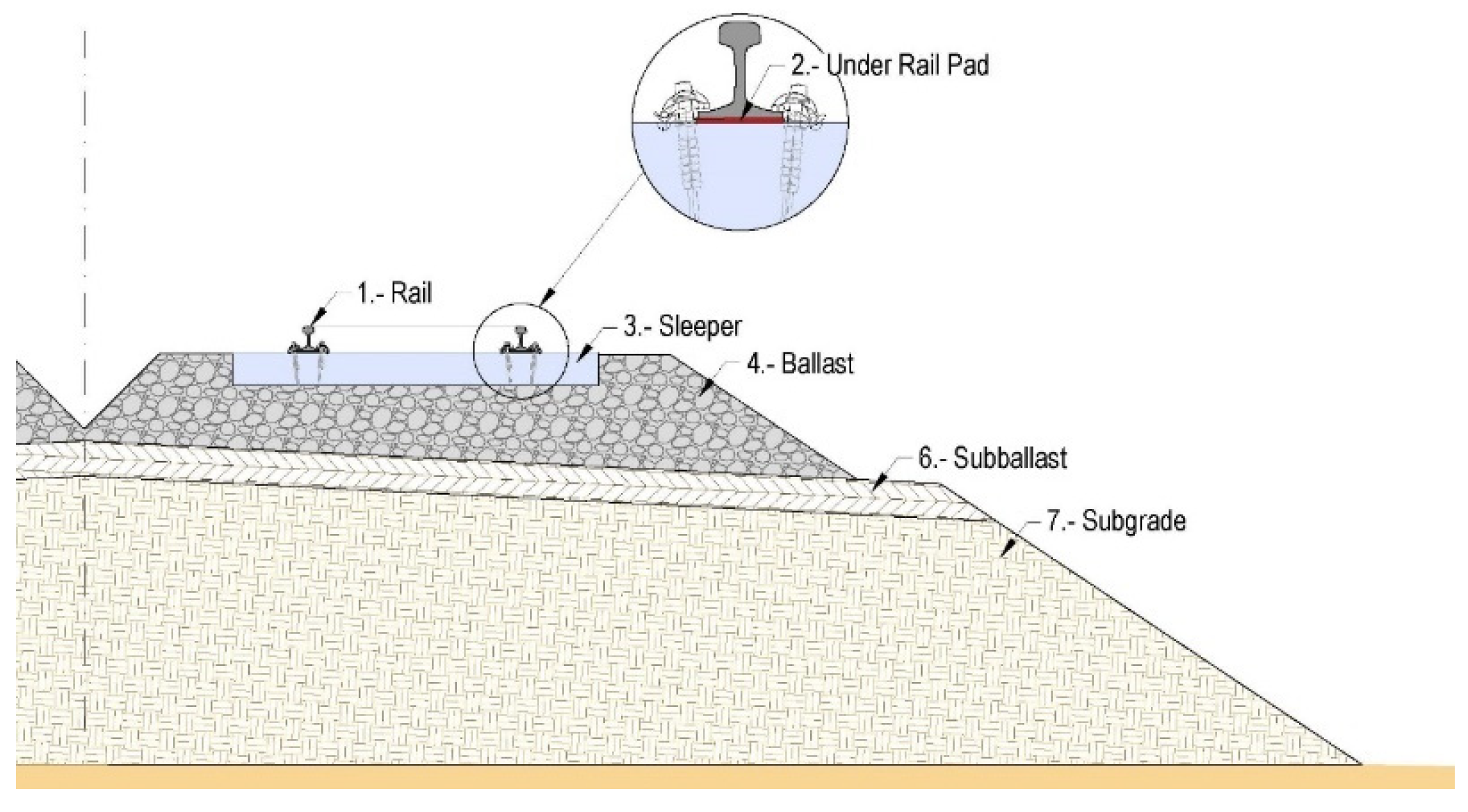
Figure 2.
Thaly –Alstom – Renfe S100 High Speed Train [4].
Figure 2.
Thaly –Alstom – Renfe S100 High Speed Train [4].
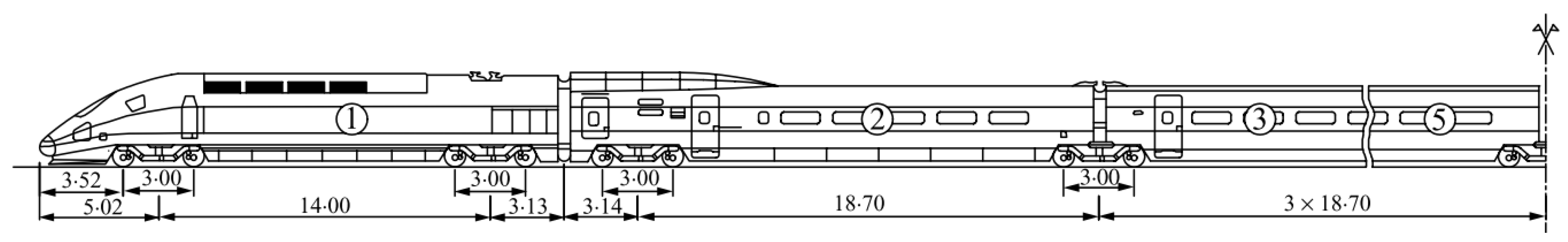
Figure 3.
Proposed Finite Element Model of the track and subgrade system: (a) Oblique view of the model (b) Cross–Section of the model.
Figure 3.
Proposed Finite Element Model of the track and subgrade system: (a) Oblique view of the model (b) Cross–Section of the model.
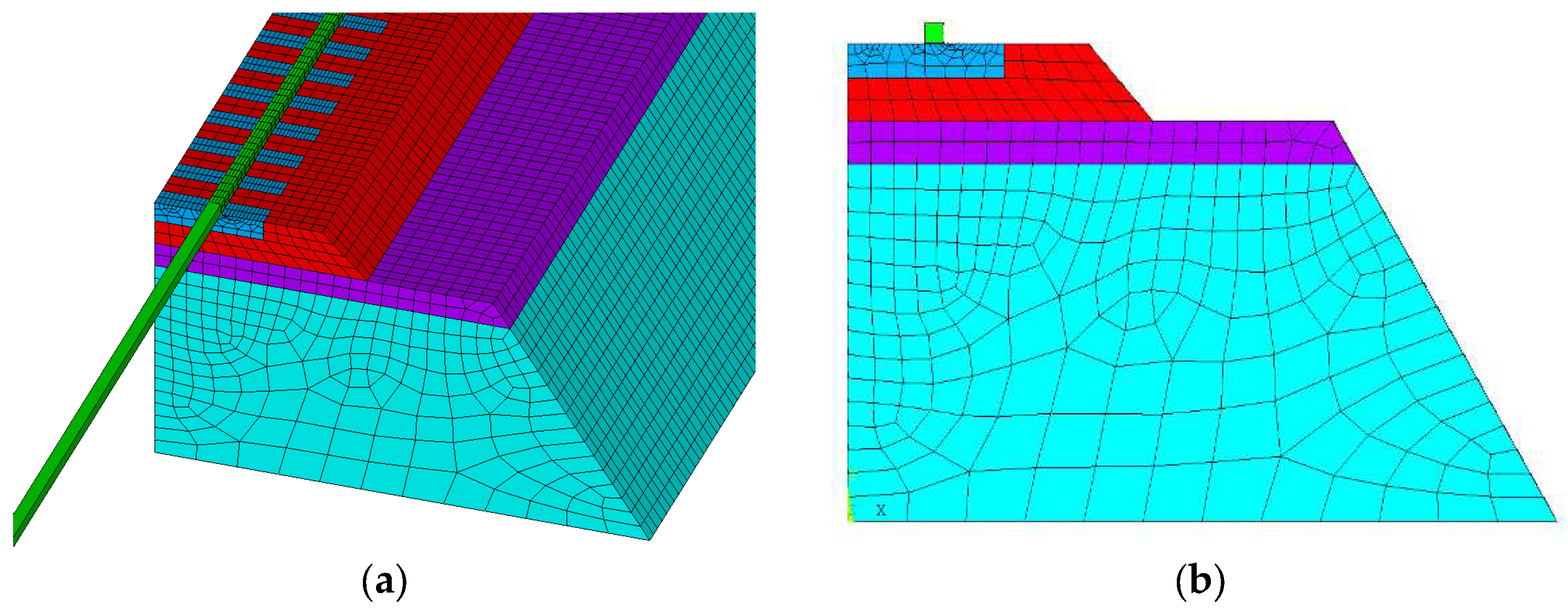
Figure 4.
Side view representation of Vehicle – Track systems interaction.
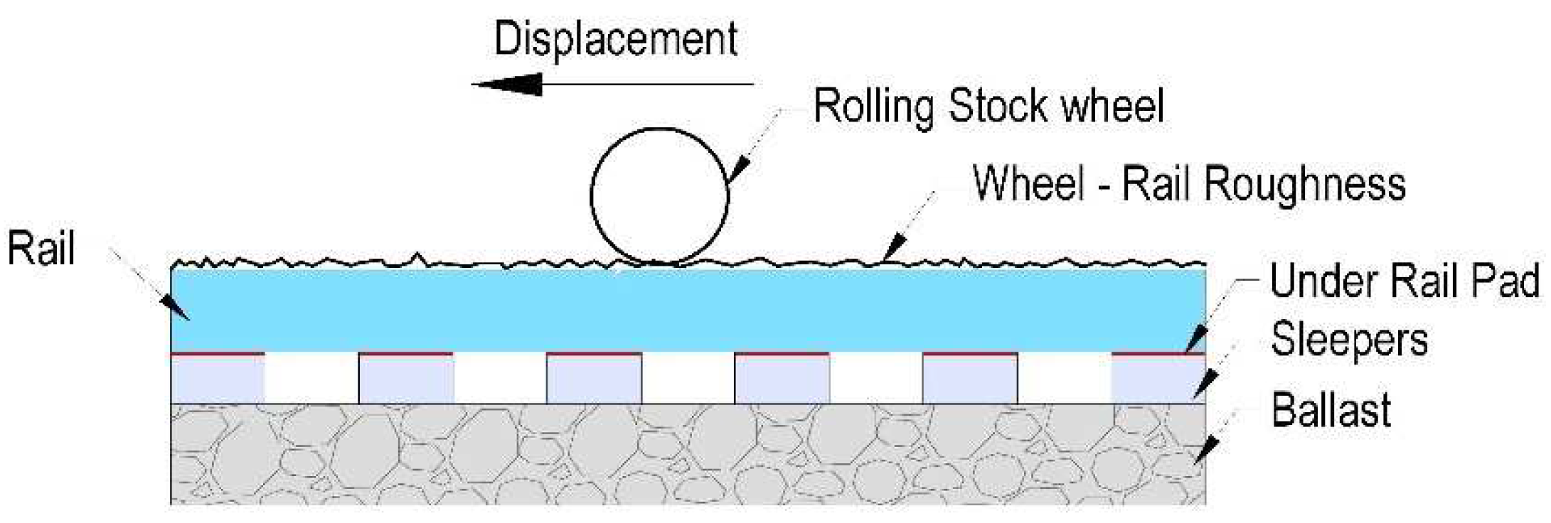
Figure 5.
Rolling Stock multibody modelled system.
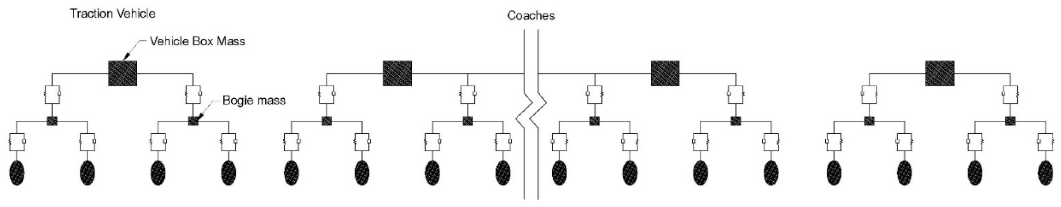
Figure 6.
Proposed model for incorporating track defects and irregularities.
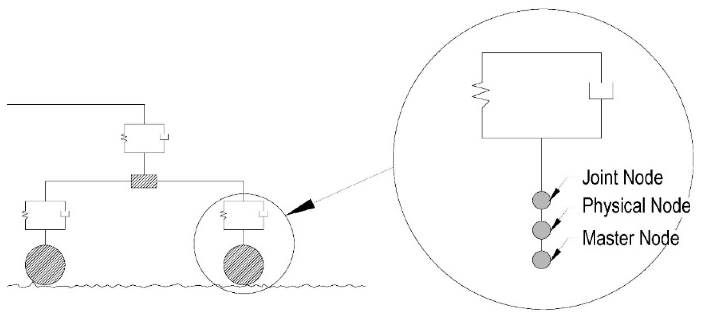
Figure 7.
Wheel – Rail model input irregularities [9].
Figure 7.
Wheel – Rail model input irregularities [9].
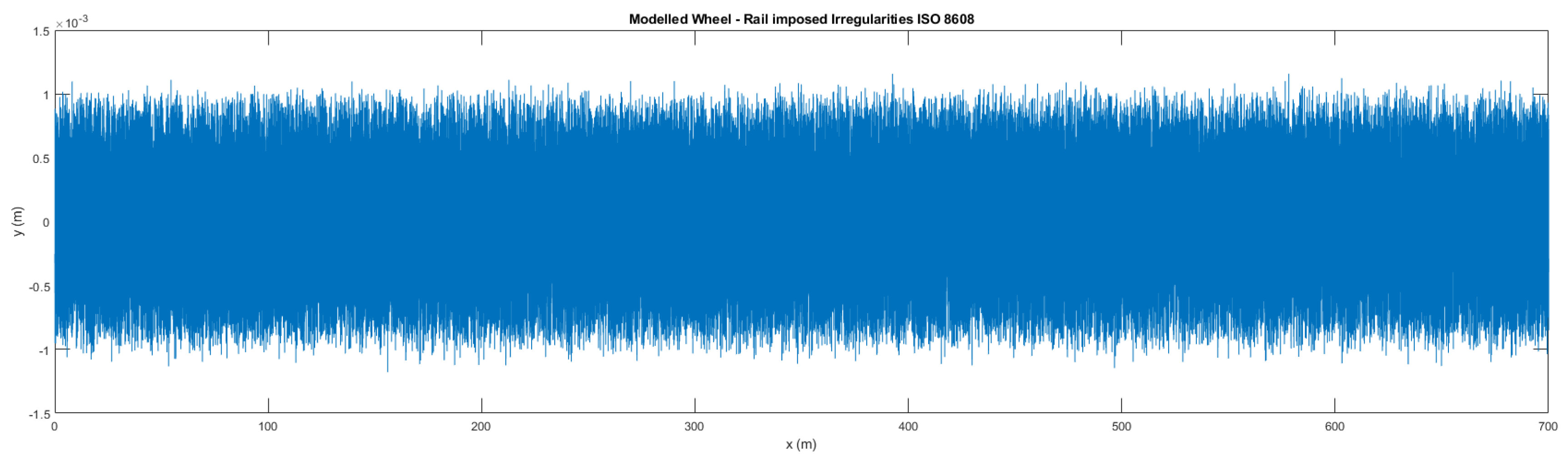
Figure 8.
Obtained acceleration vs time in the rail. Proposed model.
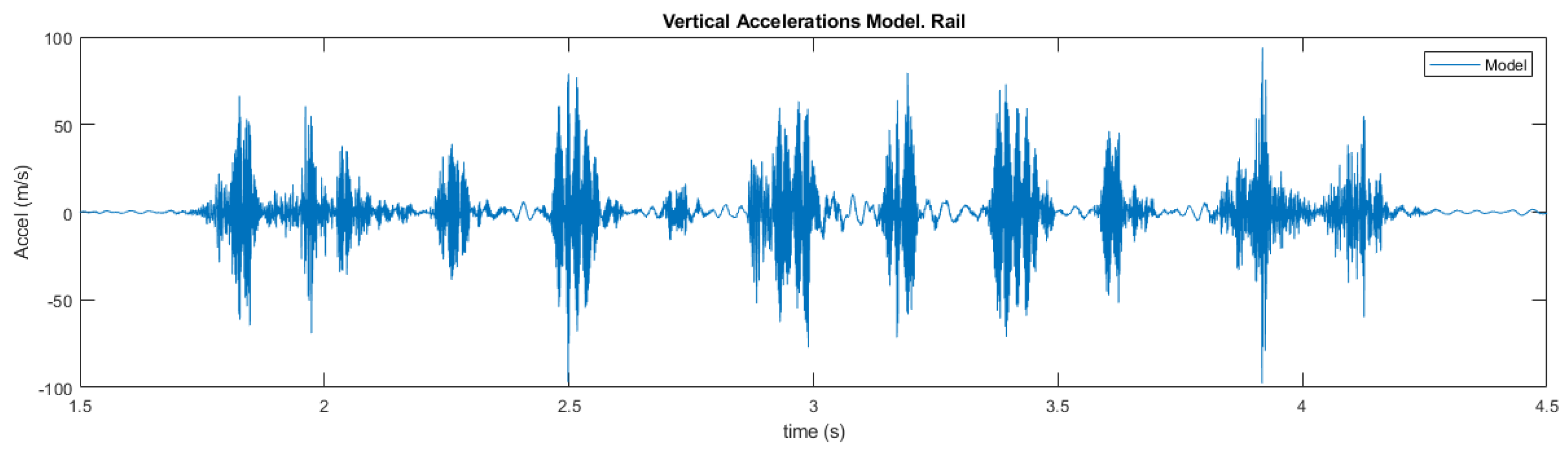
Figure 9.
Frequency domain modelled Acceleration. Proposed model.
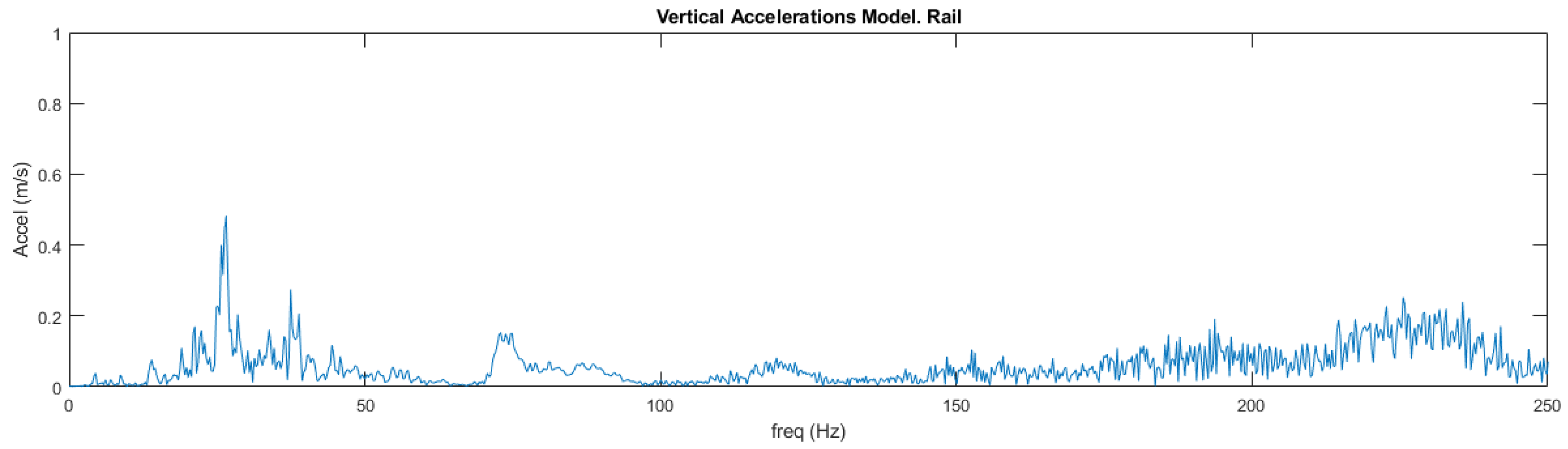
Figure 10.
Time domain measured Acceleration at 300 Km/h speed passing, with data obtained from [4].
Figure 10.
Time domain measured Acceleration at 300 Km/h speed passing, with data obtained from [4].
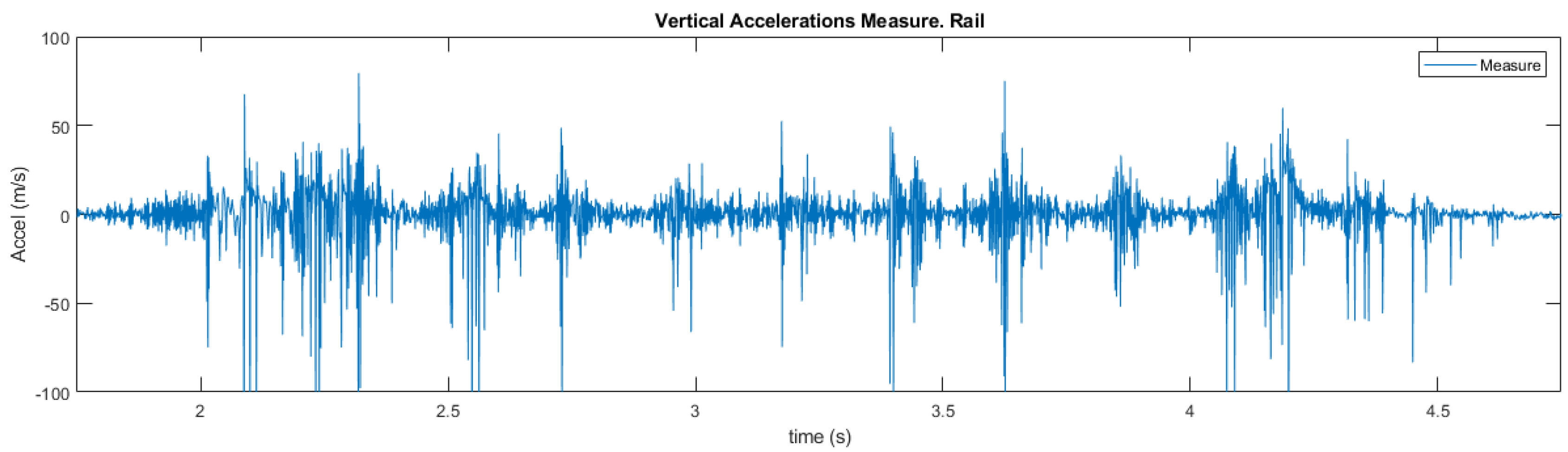
Figure 11.
Frequency domain measured Acceleration at 300 Km/h speed passing, with data obtained from [4].
Figure 11.
Frequency domain measured Acceleration at 300 Km/h speed passing, with data obtained from [4].
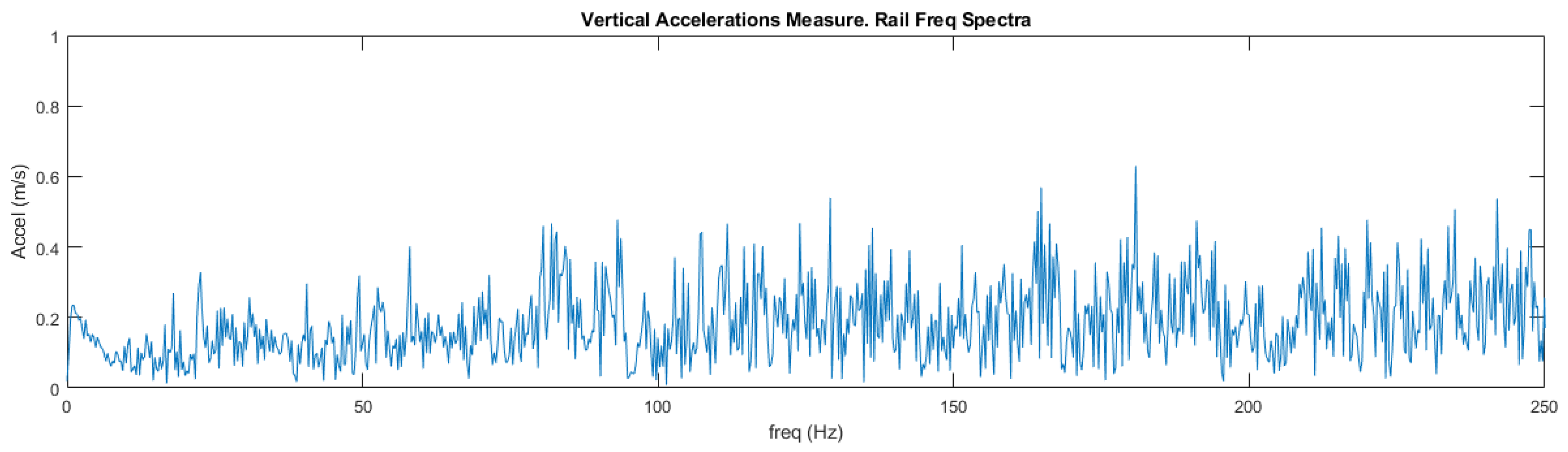

Table 1.
Reference Rolling Stock [14].
Table 1.
Reference Rolling Stock [14].
| Mu (Kg) | Mb (Kg) | Mc (Kg) |
k1*106 (N/m) |
K2*106 (N/m) |
C1*103 (N s/m) |
C2*103 (N s/m) |
|
|---|---|---|---|---|---|---|---|
| Traction car | 2048 | 2380 | 55790 | 2.45 | 20 | 2.45 | 40 |
| Side car | 2003 | 3040 | 24000 | 1.40 | 10 | 0.82 | 48 |
| Central car | 2003 | 3040 | 24000 | 1.40 | 10 | 0.82 | 48 |
Disclaimer/Publisher’s Note: The statements, opinions and data contained in all publications are solely those of the individual author(s) and contributor(s) and not of MDPI and/or the editor(s). MDPI and/or the editor(s) disclaim responsibility for any injury to people or property resulting from any ideas, methods, instructions or products referred to in the content. |
© 2024 by the authors. Licensee MDPI, Basel, Switzerland. This article is an open access article distributed under the terms and conditions of the Creative Commons Attribution (CC BY) license (http://creativecommons.org/licenses/by/4.0/).
Copyright: This open access article is published under a Creative Commons CC BY 4.0 license, which permit the free download, distribution, and reuse, provided that the author and preprint are cited in any reuse.


