1. Introduction
Due to various sources of disturbances and uncertainties, high precision control of electric drives is very challenging [
1]. It is difficult to achieve both good tracking performance and nice disturbance rejection property by using the classical proportional-integral-derivative (PID) controller, which is a one-degree-of-freedom controller and cannot realize the decoupling control of the tracking performance and disturbance rejection property [
2]. Therefore, various of advanced control algorithms with two-degree-of-freedom (TDOF) characteristics have been put forward. Among many TDOF control algorithms, TDOF PID control [
3], disturbance observer-based control (DOBC) [
4,
5,
6], and active disturbance rejection control (ADRC) [
7,
8,
9,
10] are most widely studied.
Recently, generalized active disturbance rejection control (GADRC) using generalized proportional integral control (GPIC) [
11] and generalized proportional integral observer (GPIO) is developed based on the differential flatness theory [
12]. Compared with the conventional ADRC, GADRC performs better either in disturbance rejection property for low-frequency disturbances or in suppression performance for high-frequency measurement noise [
13,
14], and thus is attracting more attentions in electric drives. Motivated by one of the original ideas in ADRC, i.e., establishing a direct connection between the classical PID control and other modern control techniques [
15,
16], the relationship between GADRC and generalized PID control has been analysed in [
17]. It is found that the GADRC can be interpreted as the generalized PID with low-pass filters or the so-called TDOF generalized PID. However, compared with generalized PID, GADRC is easier to implement since the GPIC and GPIO has specific physical interpretation. In GADRC, the PI regulator in GPIC and the one in GPIO can be designed based on the same principle because of the duality between GPIC and GPIO. Therefore, the key in designing the GADRC is to design the PI regulator. Though GADRC has good control performance when the control gain is known, it performs poor when the control gain is unknown or variable [
18]. To improve the system’s robustness to parameter variations, adaptive PI regualtors are usually employed.
There are generally two methods to realize adaptive PI control. One method is the model reference adaptive control (MRAC) based on disturbance esitmation [
19], and thus is suitable for systems with parameters vary in small range. The other method is the model reference adaptive identification (MRAI) based on parameters identification [
18], it can be applied in systems with parameters vary in a large range. In [
18], accurate mechanical parameters are identified in an adptive PI observer, of which the design process is complicated. In addition, the speed tracking error is not considered. In this paper, an adaptive PI controller is designed to eliminate the speed trakcing error under unknown mechanical parameters. Two practical issues: the low-pass filter used for feedback speed and the Coulomb friction torque, are carefully dealt with. A modified motion equation considering these two practical issues is introduced and the relationship between the identified parameters and their actual values are clarified.
The rest of this article is organized as follows.
Section 2 introduces the mathematical model of the mechanical system and the conventional PI controller for speed control system.
Section 3 presents the designed PI controller and two practical issues in real applications. Simulation results and the analysis are shown in
Section 4. Finally, discussion about the findings are drawn in
Section 5.
2. Conventional PI Controller for Speed Control
2.1. Mathematical Model of the Speed Control System
The feedback control law is designed to attenuate the speed reference tracking error as desired. According to the feedback control law, the control output, i.e., the torque reference, can be deduced. Therefore, the system model should be expressed as a function of the torque references. Considering the uncertainties of the moment of inertia
J, the nominal value
is usually employed in the control system.
where
is the mechanical angular velocity,
and
are the electromagnetic torque and its reference,
B is the viscous friction torque coefficient,
is the load torque,
and
are the control gain and its nominal value,
is the disturbance torque caused by the load torque and viscous friction torque,
is the disturbance caused by the lumped disturbance torque with a known inertia,
is the total disturbance when considering the inertia mismatches.
The speed reference can be denoted as
, then the speed tracking error can be expressed as
, and we have
2.2. Proportional Control and Its Shortcomings
When using proportional control, the desired speed tracking error convergence law is designed as
where
is the proportional gain.
Substituting (
3) into (
2) yields
In (
4), the mechanical angular speed
, and the total disturbance
are required. In real systems,
is unknown. One simple way to solve this problem is just to neglect the total disturbance. In addition,
is usually calculated by the derivative of the position, which is generally obtained from the position sensor such as the encoder or resolver. Due to the quantization noise in the measurement of the position, the measured position and the speed calculated by the classical frequency method is subjected to the measurement noise. Denoting
as the quantization noise in the measured speed, there is
.
When
is neglected and
is used for feedback, the actual torque reference can be expressed as
In the practical system, the reference torque limit is usually applied as follows.
where
and
are the saturated torque reference and the maximum torque reference.
According to (
1), the relationship between the torque reference and the total disturbance can be expressed by
Without considering the saturation of the torque reference, the system output can be obtained by substituting (
5) into (
7) yields
It can be seen that a constant total disturbance causes a steady-state speed tracking error, which is inverse proportional to the proportional gain . Increasing reduces tracking error but deteriorates the measurement noise suppression performance at the same time. Consequently, many methods are developed to reduce the effect of the disturbance and the measurement noise, among which PI controller is a classical one.
2.3. Physical Interpretation of the Integrator in PI Controller
When the total disturbance
in (
4) is substituted by its estimated value
, the control output can be modified as
Substituting (
9) into (
2) yields
where
id the estimation error of the total disturbance.
One Lyapunov function can be chosen as
where
is the gain for estimating disturbance.
The derivative of the Lyapunov function expressed by (
11) can be deduced as
It is easy to know that the system can be stable by adopting the adaptive law expressed by (
13)
Assuming the total disturbance is contant or the derivative of the total disturbance is zero, the estimated total disturbance can be expressed as
Therefore, the torque reference expressed by (
9) can be modified as
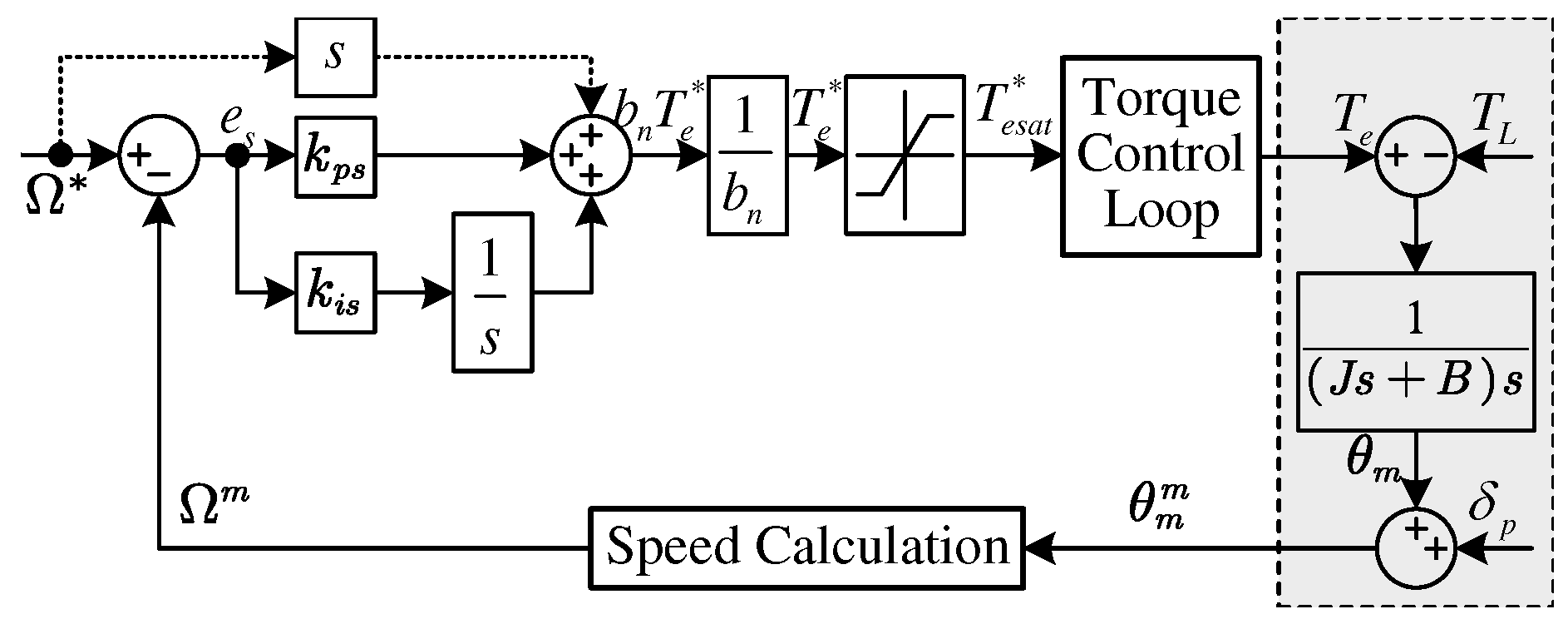
The block diagram of the designed controller is shown in
Figure 1, which is the same as a PI controller. As a result, it is known that the integrator in PI controller has the function of estimating disturbance.
2.4. Dynamic Performance of the Speed PI Control System
In real applications, the measured speed as
is used for feedback, and thus the actual torque reference is modified as
According to (
1), the relationship between the torque reference and the nominal disturbance can be expressed by
Substituting (
16) into (
17), the system output can be obtained as
where
is the control gain ratio.
When the moment of inertia is known, i.e.,
, the system has an ideal tracking performance under no disturbance and the characteristic polynomial is usually set as
, where
is the bandwidth of the speed control loop. The two gains in PI controller can be calculated by
and
. However, when the moment of inertia is unknown or it varies with operating conditions,
, the system dynamic performance will degrade. If we write the characteristic polynomial of the closed-loop control system as
, then the actual damping ratio
and the actual natural frequency
can be calculated by
It can be seen that both the actual damping ratio and the actual natural frequency decreases as increases, leading to a larger overshoot in the step response as well as a slower dynamic performance. To solve this problem, adaptive PI controller is developed in this paper.
3. Adaptive PI Controller for Speed Control Based on MRAI
3.1. Adaptive PI Controller Considering Mechanical Parameters Uncertainties
The motion equation (
1) can also be expressed as
where
consists of the disturbance caused by the load torque and the torque tracking error.
The state equation of the speed tracking error can be expressed as
Therefore, the ideal torque reference when using proportional control can also be deduced as
Denote the estimated values of
J,
B, and
as
,
and
, the actual torque reference can be expressed as
Substituting (
23) into (
2) yields
where
,
, and
are the estimation error of inertia, viscous friction coefficient, and disturbance torque, respectively.
Choosing a Lyapunov function as
where
,
, and
are the adaptive gain for estimating the inertia, viscous friction coefficient, and disturbance torque.
The derivative of the Lyapunov function expressed by (
25) can be deduced as
It can be seen from (
26) that the system can be stable by setting the second item in the right hand of the formula to zero, i.e.,
With assumption that the actual inertia, viscous friction coefficient, and disturbance torque are constant, the adaptive law for the three estimated parameters can be expressed by
where
,
, and
are the initial values.
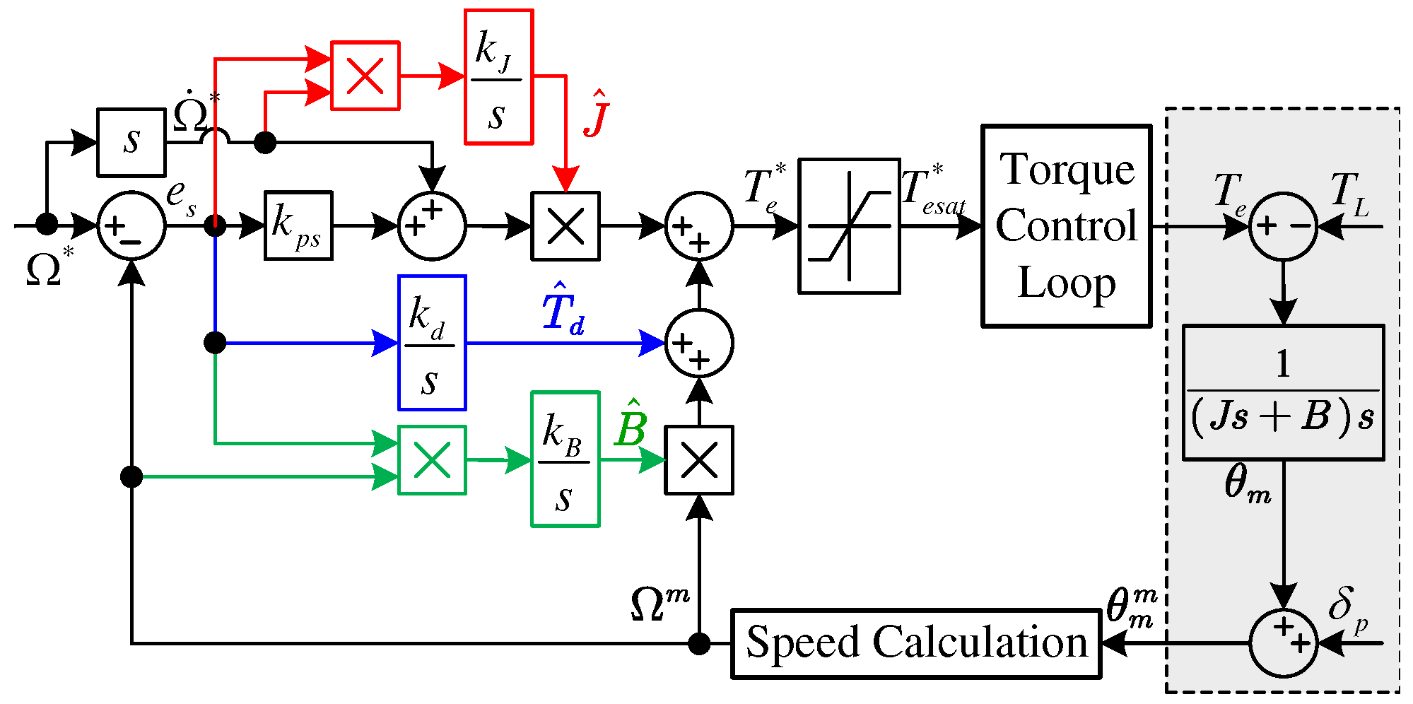
According to (
23) and (
28), the block diagram of the adaptive PI controller can be shown in
Figure 2.
3.2. Practical Issues in Real Applications
In real applications, a LPF is usually used for attenuating the speed measurement noise and thus the feedback speed is the filtered speed
. Assuming a first-order LPF with a time constant of
is employed, the realtionship between
and
can be expressed as
Using
as the output and considering the Coulomb friction torque coefficient
, the motion equation is modified as
To obtain smoothed identified parameters, sinusoidal speed is usually employed as the persistent excitation signal. Assuming the sinusoidal speed has an angular frequency of , and it can be expressed as the sum of an AC component and DC component, i.e., , there is .
If there is no offset in the speed,
, then the Coulomb friction torque is an AC signal that in phase of the real speed
, and thus it can be approximated by
, where
and
are the incremental inertia and incremental viscous friction torque coefficient, and they depends on
and
. As a result, the motion equation can be rewritten as
If a large offset is added in the speed reference so that the speed becomes unipolar, then the Coulomb friction torque is a constant torque such that it can be treated as part of the load torque. The motion equation can be rewritten as
Denote
,
, and
as the equivalent values of inertia, viscous friction torque coefficient, and load torque, we can express the motion equation in a unified form as
In the case of bipolar speed,
,
, and
are expressed as
In the case of unipolar speed,
,
, and
are expressed as
Since a LPF is used for the measured speed, a same LPF should be used for the speed reference so that the actual speed can track the real speed reference. Denote the filtered speed reference as
. When using the motion equation expressed by (
33), the adaptive law for the identified parameters can be modified as
where
,
, and
are the initial values.
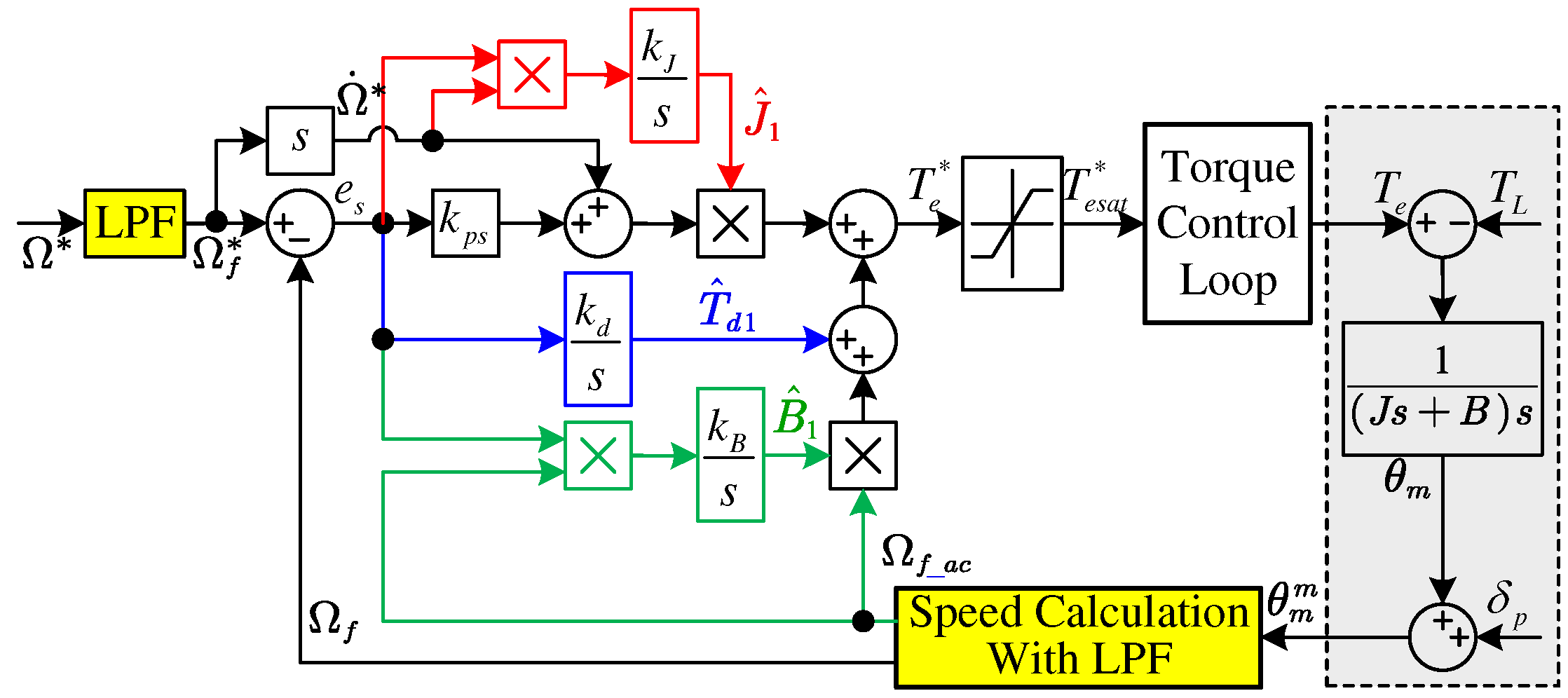
The block diagram of the modified adaptive PI control system is shown in
Figure 3.
4. Simulation Verification
In this section, experiments are conducted to verify the effectiveness of the proposed adaptive PI controller and the theoretical analysis. A comprehensive comparison is made between the conventional PI controller and the proposed adaptive PI controller.
4.1. System Configuration
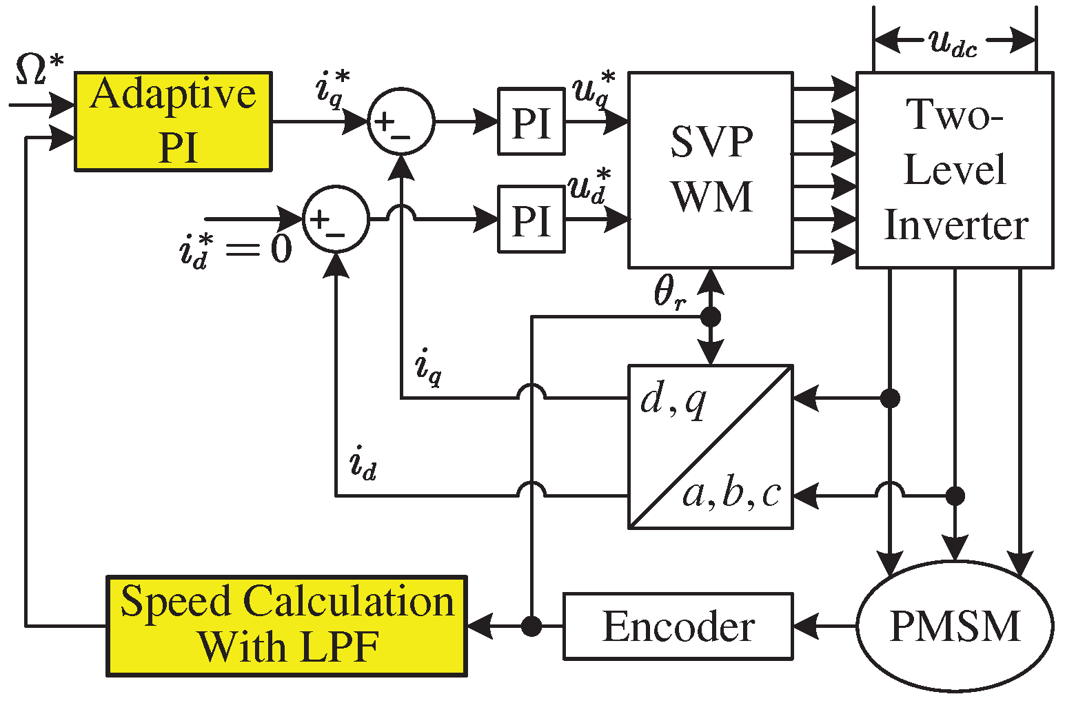
The system configuration is shown in
Figure 4.
Table 1 shows the parameters of the examined PMSM. In Simulations, the incremental encoder has a resolution of 2500 pulse per round (PPR). The rotor field-oriented control (RFOC) strategy with
and space vector pulse width modulation (SVPWM) is adopted. The DC Bus voltage provided by a programmable DC power supply is set as 150V. The sampling frequency and the control frequency for current and the speed control are the same, i.e., 10 kHz. Decoupled PI Controller is employed for current control and the bandwidth is set as 2000 rad/s. The delay in torque control loop is so small that it can be neglected in the speed control system. The current limit is set as 9 A. The speed is calculated by using the classical frequency method and a first-order LPF with a time constant of 1 ms is employed to suppress the measurement noise.
In the simulation, rad/s, , , . Three control systems: the conventional PI controller, the adaptive PI controller without identifying , and the adaptive PI controller identifying , are tested. The simulation time is set as 5 s. At the time instant of 1 s, sinusoidal speed reference is given under no load and the adaptive PI control is enabled. At the time instant of 3 s, a load is stepped from 0 Nm to 2 Nm.
4.2. Simulation Results under Initial Inertia of 1
The initial inertia is set as 1
. When a bipolar sinusoidal speed reference expressed by
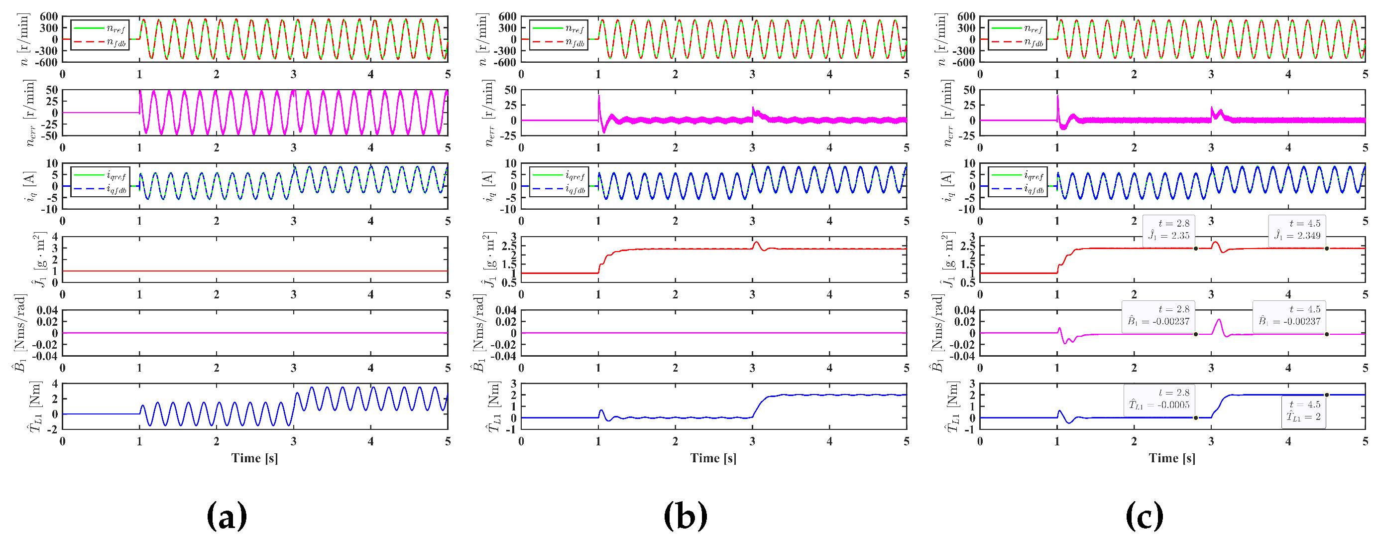
r/min is employed, the simulation results of the three control systems without considering the Coulomb friction torque are shown in
Figure 5. From
Figure 5(a), it can be seen that the conventional PI controller has a poor tracking performance due to the mismatched inertia. The identified load torque is oscillating because it is an integral of the speed tracking error, which is sinusoidal. In
Figure 5(b), the inertia is identified but the viscous friction torque coefficient is not. The oscillation in the identified load torque is greatly reduced, but not eliminated. Meanwhile, the identified inertia oscillates at the frequency of 10 Hz, which is twice of the frequency of the sinusoidal speed reference. The oscillation can be eliminated by identifying load torque, inertia and viscous friction torque coefficient simultaneously, as shown in
Figure 5(c). It can be seen that the actual inertia 2.35
can be identified,
Nms/rad, which is very closed to
Nms/rad, and the identified load torque at 2.8 s are -0.0005 Nm and 2 Nm, which are almost the same as the actual values. The error is caused by some unmodelled dynamics in the digital control system, such as the delay in sampling and control.
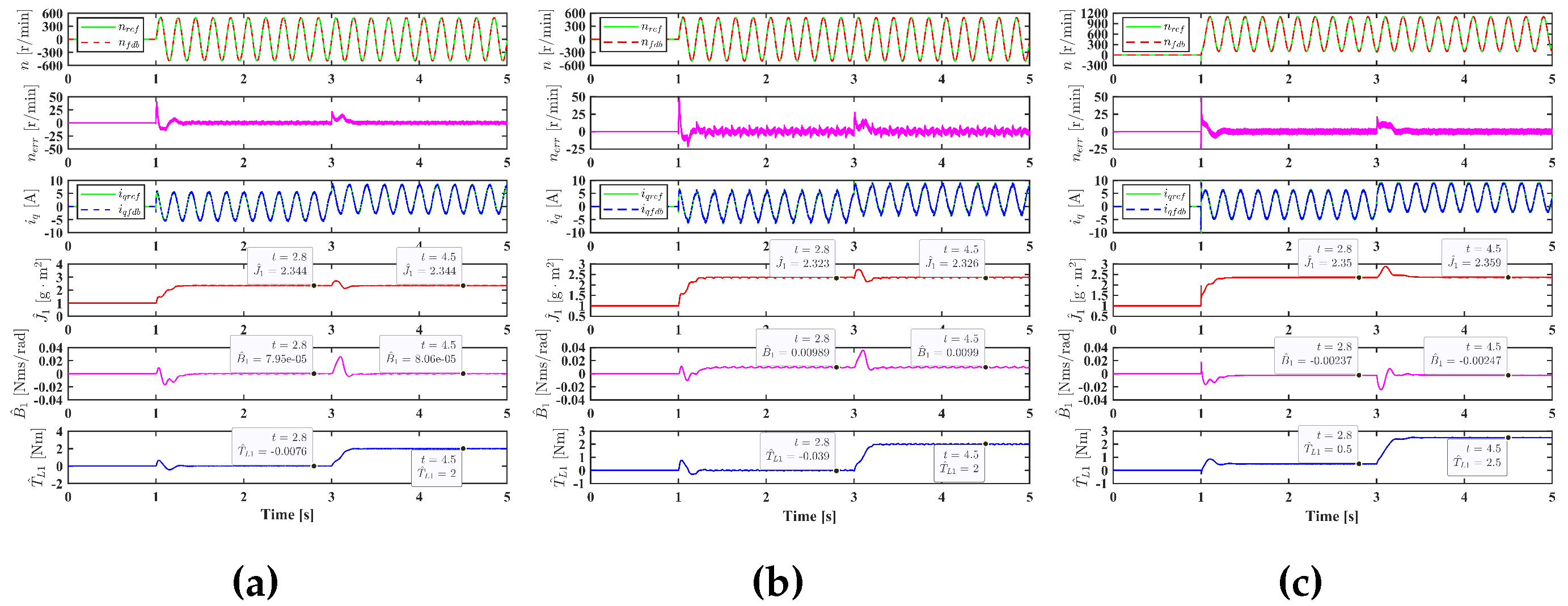
When considering the Coulomb friction torque, simulation results of the adaptive PI controller will be affected. In
Figure 6(a) and (b),
is 0.1 Nm and 0.5 Nm respectively, the identified inertias are merely affected, they are 2.344
and 2.323
, however, the identified viscous friction torque coefficients are greatly affected, they become
Nms/rad and
Nms/rad. This is because the incremental ineritia
caused by the Coulomb friction torque is very small while the incremental viscous friction torque coefficient
is large. The Coulomb friction torque causes the oscillation of the speed tracking error and thus leads to the oscillation of the identified parameters. To solve this problem, a unipolar speed reference expressed by
r/min can be employed, as shown in
Figure 6(c).
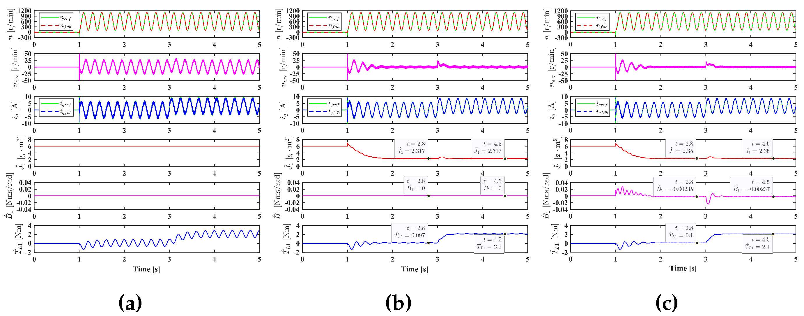
To further verify the effectiveness of the proposed adaptive PI controller, the initial inertia is increased to 6
and the Coulomb friction torque coefficient
is set as 0.1 Nm, simulation results are shown in
Figure 7. Similarly, it can be seen that the conventional PI controller has a poor tracking performance, the speed tracking error can be greatly reduced by identifying ineritia, but it cannot be eliminated if the viscous friction torque coefficient is not identified.
5. Discussion
In this paper, the PI controllers for speed control of electric drives are studied. The conventional PI controller is designed based on Lyapunov function so that the physical interpretation of the integrator is revealed. The influence of control gain on system dynamic performance is investigated; it is discovered that increasing control gain causes a decrease in both the damping ratio and the natural frequency. To improve the system robustness to parameter variations, an adaptive PI controller based on the model reference adaptive control is developed in this paper. In real applications, the low-pass filter used for the feedback speed and the Coulomb friction torque has an effect on parameters identification. To solve these two problems, a modified motion equation is introduced and the relationship between the identified parameters and their actual values are investigated.
It is worth pointing out that the principle of the adaptive PI controller is to divide the total disturbance torque into AC and DC components, the DC component disturbance is identified by the integral of the speed tracking error, whereas the AC component disturbance is identified by an adaptive linear neuron (ADALINE) neural network, in which the feedback speed and its derivative are the basis, while the equivalent inertia and the equivalent viscous friction torque coefficient are two weights need to be trained. Therefore, the AC disturbance caused by other unmodelled dynamics can also be identified and compensated.
Author Contributions
Conceptualization, Y. Zuo; methodology, Y. Zuo; formal analysis, Y. Zuo; investigation, Y. Zuo; writing—original draft preparation, Y. Zuo; writing—review and editing, S. S. Zhu, Y. Cui, C. Liu, and X. Lin; visualization, Y. Zuo, Y. Cui, and X. Lin; supervision, C. Liu.; project administration, S. S. Zhu, Y. Cui, and C. Liu; funding acquisition, S. S. Zhu and C. Liu. All authors have read and agreed to the published version of the manuscript.
Funding
This research was funded in part by National Key Laboratory of Science and Technology on Helicopter Transmission grant number HTL-A-21G01, and in part by China Postdoctoral Science Foundation grant number 2023M741674. The APC was funded by XXX.
Conflicts of Interest
The authors declare no conflict of interest.
References
- Yang, J. ; Chen,W. H.; Li, S.; Guo, L.; Yan, Y. Disturbance/Uncertainty Estimation and Attenuation Techniques in PMSM Drives—A Survey. IEEE Transactions on Industrial Electronics 2017, 64, 3273–3285. [Google Scholar]
- Zuo, Y.; Zhu, X.; Quan, L.; Zhang, C.; Du, Y.; Xiang, Z. Active Disturbance Rejection Controller for Speed Control of Electrical Drives Using Phase-Locking Loop Observer. IEEE Transactions on Industrial Electronics 2019, 66, 1748–1759. [Google Scholar] [CrossRef]
- Harnefors, L.; Saarakkala, S.E.; Hinkkanen, M. Speed Control of Electrical Drives Using Classical Control Methods. IEEE Transactions on Industry Applications 2013, 49, 889–898. [Google Scholar] [CrossRef]
- Chen,W. H. Disturbance Observer Based Control for Nonlinear Systems. IEEE/ASME Transactions on Mechatronics 2004, 9, 706–710.
- Chen, W.H.; Yang, J.; Guo, L.; Li, S. Disturbance-Observer-Based Control and Related Methods—An Overview. IEEE Transactions on industrial electronics 2015, 63, 1083–1095. [Google Scholar] [CrossRef]
- Sariyildiz, E.; Oboe, R.; Ohnishi, K. Disturbance Observer-Based Robust Control and Its Applications: 35th Anniversary Overview. IEEE Transactions on Industrial Electronics 2020, 67, 2042–2053. [Google Scholar] [CrossRef]
- Gao, Z. Scaling and Bandwidth-Parameterization Based Controller Tuning. In Proceedings of the Proceedings of the American Control Conference, 2003; Vol. 6, pp. 4989–4996.
- Han, J. From PID to Active Disturbance Rejection Control. IEEE transactions on Industrial Electronics 2009, 56, 900–906. [Google Scholar] [CrossRef]
- Huang, Y.; Xue, W. Active Disturbance Rejection Control: Methodology and Theoretical Analysis. ISA Transactions 2014, 53, 963–976. [Google Scholar] [CrossRef] [PubMed]
- Gao, Z. On the Centrality of Disturbance Rejection in Automatic Control. ISA Transactions 2014, 53, 850–857. [Google Scholar] [CrossRef] [PubMed]
- Sira-Ramírez, H. On the Generalized PI Sliding Mode Control of DC-to-DC Power Converters: A Tutorial. International journal of control 2003, 76, 1018–1033. [Google Scholar] [CrossRef]
- Sira-Ramírez, H.; Luviano-Juárez, A.; Ramírez-Neria, M.; Zurita-Bustamante, E.W. Active Disturbance Rejection Control of Dynamic Systems: A Flatness Based Approach; Butterworth-Heinemann, 2018.
- Zuo, Y.; Mei, J.; Jiang, C.; Yuan, X.; Xie, S.; Lee, C.H.T. Linear Active Disturbance Rejection Controllers for PMSM Speed Regulation System Considering the Speed Filter. IEEE Transactions on Power Electronics 2021, 36, 14579–14592. [Google Scholar] [CrossRef]
- Zuo, Y.; Chen, J.; Zhu, X.; Lee, C.H.T. Different Active Disturbance Rejection Controllers Based on the Same Order GPI Observer. IEEE Transactions on Industrial Electronics 2022, 69, 10969–10983. [Google Scholar] [CrossRef]
- Wenchao Xue. ; Yi Huang. Comparison of the DOB Based Control, a Special Kind of PID Control and ADRC. In Proceedings of the Proceedings of the 2011 American Control Conference, San Francisco, CA, 2011; pp. 4373–4379.
- Zhong, S.; Huang, Y.; Guo, L. A Parameter Formula Connecting PID and ADRC. Science China Information Sciences 2020, 63, 192203. [Google Scholar] [CrossRef]
- Lin, P.; Wu, Z.; Fei, Z.; Sun, X.M. A Generalized PID Interpretation for High-Order LADRC and Cascade LADRC for Servo Systems. IEEE Transactions on Industrial Electronics 2022, 69, 5207–5214. [Google Scholar] [CrossRef]
- Zuo, Y.; Mei, J.; Zhang, X.; Lee, C.H.T. Simultaneous Identification of Multiple Mechanical Parameters in a Servo Drive System Using Only One Speed. IEEE Transactions on Power Electronics 2021, 36, 716–726. [Google Scholar] [CrossRef]
- Nguyen, A.T.; Rafaq, M.S.; Choi, H.H.; Jung, J.W. A model reference adaptive control based speed controller for a surface-mounted permanent magnet synchronous motor drive. IEEE Transactions on Industrial Electronics 2018, 65, 9399–9409. [Google Scholar] [CrossRef]
|
Disclaimer/Publisher’s Note: The statements, opinions and data contained in all publications are solely those of the individual author(s) and contributor(s) and not of MDPI and/or the editor(s). MDPI and/or the editor(s) disclaim responsibility for any injury to people or property resulting from any ideas, methods, instructions or products referred to in the content. |
© 2024 by the authors. Licensee MDPI, Basel, Switzerland. This article is an open access article distributed under the terms and conditions of the Creative Commons Attribution (CC BY) license (http://creativecommons.org/licenses/by/4.0/).
