1. Introduction
In situ vascular tissue engineering is an ideal
strategy to treat small diameter vascular diseases and promote the in situ
regeneration of damaged small diameter blood vessels. However, the blood flow
in small diameter blood vessels is slow, and thrombosis is easy to form on the
surface of the official cavity [
1], and the
long term patency is poor, which restricts the clinical application
transformation of small diameter tissue engineering blood vessels (Φ<6mm). [
2] In order to achieve long term patency, this
study aims to regulate cell behavior, induce cell function expression, and
guide vascular structure reconstruction and functional regeneration by
regulating the topological structure and biological properties of electrospun
fibers, further achieve rapid endothelialization of small diameter tissue
engineering blood vessels. [
2]
In biological tissues, fibers often exist in a crimped
form, such as the aorta, intestines, ligaments, and tendons. [
3] The inner elastic membrane and the elastic
membrane of the middle blood vessel wall are crimped, and the main component is
elastin. The elasticity of the blood vessel wall mainly depends on these
elastic tissues. However, the crimped electrospun fiber scaffolds used in small
diameter vascular tissue engineering are less, and more are used in ligaments
and tendons. Pen hsiu Grace Chao et al [
3]
prepared poly L-lactic acid (PLLA) fibers exhibited nonlinear stress-strain
behavior with a significant increase in the toe region in correlation to the
degree of crimp. In addition to mimicking the nonlinear stress-strain behavior
of ligaments, PLLA fibers are instructive in cells morphology and promote
ligament phenotypic gene expression. Crimped poly L-lactic acid/poly
(3-hydroxybutyrate-co-3-hydroxyvalerate) (PLLA/PHBV) fibers prepared by
Zhenying Chen et al [
4] to mimick tendon
tissue and promote collagen production and assembly more effectively under
mechanical stimulation. Therefore, in this paper, crimped PLA fibers were
prepared to mimick the crimped structure and nonlinear mechanical properties of
the elastic membrane of blood vessel wall, and promote the lateral alignment
and growth of HUVECs.
Although electrospun fiber scaffolds are widely
used in vascular tissue engineering, one major limitation is the dense fibers,
small pore size, and consequently poor cell infiltrarion. [
5] In order to overcome this shortcoming, a variety
of techniques have been introduced, including the introduction of pore causing
agents, the change of fiber diameter, the light patterning and the ultraviolet
radiation. [
5] In terms of light patterning, S
D McCullen et al [
6] processed PLA fibers by
excimolecular laser to form 150, 300 and 600um microporous arrays, and human
adapoid derived stem cells (HASCs) formed good adhesion and proliferation on
the fibers, and formed patterning growth around the microporous arrays. Benjamin
Li Ping Lee et al [
5] processed PLLA fibers by
femtosecond laser to form 50, 100 and 200um microporous arrays. Human
mesenchymal stem cells (HMSCs) were implanted on fibers of different
microporous arrays, exhibiting different morphology, but similar proliferation
rate. Animal studies indicate that microporous array fibers facilitate
endothelial cells (ECs) ingrowth as well as drastically increase M2 macrophage
and overall cell infiltration. In this paper, laser ablation was performed on
PLA fibers in different crimped states, and micropore arrays with different
coaxial ratios were processed by utilizing the anisotropic heat conduction of
the fiber. In addition, thermal induced phase separation and vapor induced
phase separation were adopted during electrospinning, and three levels of pore
structure was finally formed, which enhanced the infiltrarion of HUVECs and
realized patterned cell growth. The crimped PLA fiber with three levels of pore
structure promoted rapid endothelialization of blood vessels, which provides
theoretical and practical reference for the design and development of small
diameter tissue engineering blood vessels.
2. Materials and methods
2.1. Preparation of PLA fiber with two levels pore structure
Preparation of PLA fiber with two levels pore
structure: A certain amount of PLA was dissolved in the mixed solvent of
dichloromethane (DCM) and N, N-dimethylformamide (DMF) (DCM: DMF= 4:1) to
prepare 12wt% PLA solution, which was stirred by magnetic stirrers for 1.5h
until the PLA was completely dissolved. The PLA solution was left for 5 minutes
to discharge the bubbles, then inhaled into a 10mL syringe, left for 5 minutes
to discharge the bubbles again, and then the PLA solution was injected into the
spinning tube. Connect the positive terminal of the high voltage power supply
to the spinning needle and the negative terminal to the collection device (wrap
a layer of aluminum foil on the roller). The spinning voltage is 15kV, the feed
speed is 13.3uL/min, the needle type is 20G, the jet distance is 20cm, the
temperature is 23.5℃, the humidity is 65%RH, and the spinning time is 5h.
Finally, the PLA fiber was dried in a drying oven at 40℃ for 24h.
Preparation of smooth PLA fiber: The solvent was
hexafluoroisopropanol (HFIP), the spinning temperature was 24.5℃, the humidity
was 30%RH, and the other parameters were the same as the PLA fiber with two
levels pore structure.
2.2. Characterization
The microstructure of electrospun fibers was
observed by scanning electron microscopy (SEM). The crimped state function was
computed by Image J. Crystallinity was measured by X-ray diffractometer (XRD).
The mechanical properties were measured by an ultra high precision static
microforce experimental machine with a tensile speed of 5mm/min.
Among them, the degree of crimp was measured by
crimped state function, as shown in formula (1):
In formula (1), x, y are the position
of the fiber, A is the amplitude of the fiber crimped state function,
and w is the angular frequency of the fiber crimped state function.
2.3. The fibers pretreatment and planting cells
(1) Fiber pretreatment: we took three 24 well
plates, the cell slides were placed at the bottom of the 24 well plates, double
sided tape was pasted on the cell slide, the fibers were pasted above the
double sided tape, and the fibers must be flat when pasting. (2) Fiber
sterilization treatment: the fibers were soaked with 75% medical alcohol
overnight, cleaned with sterile cold phosphate (PBS) for 3 times, and finally
irradiated with ultraviolet lamp for 0.5h to further sterilization. (3) Cell
treatment: the cells were cultured to 90% confluent, and digested with
pancreatic enzyme. After counting, the cell concentration was adjusted to 1*104/ml.
(4) Cell inoculation: In order to enhance the biocompatibility of the fibers,
0.1% gelatin was added to the 24 well plates and incubated for 30min. After
cleaning with aseptic PBS three times, 1mL of cell suspension with adjusted
concentration was added to the 24 wells plates. The 24 wells plates were placed
at an incubator of 37℃ and 5% CO2 for 12h. The cell morphology was observed
with an inverted microscope, and the subsequent experiments were carried out
after cell adhesion.
2.4. Cell proliferation analysis
After a total of three 24 well plates were used to culture cells respectively for 1d, 3d, and 5d, the superserum was absorbed and transferred to the 96 well plate. 0.1mL CCK-8 solution was added to each hole under the condition of avoiding light. The 24 wells plates were placed at an incubator of 37℃ and 5% CO2 for 2h. The absorbance (OD) value was measured at 450nm wavelength using an enzymoleter. Each experiment was repeated three times to take the average value.
2.5. Cell morphology Observation
(1) After the cells were cultured for 3d, 4% paraformaldehyde was added into each cell slide, the cells were covered horizontally evenly, and fixed for 15min, and washed with PBS twice in 5min. The edge of the cell slide was wiped dry with filter paper; (2) TRITC Phalloidin labeled with Rhodamine tetramethyl isothiocyanate (TRITC Phalloidin) was diluted to 1:200, and added to the 24 well plates. The cells were covered horizontally evenly, and incubated at 37℃ for 20min under dark condition, and washed with PBS 3 times in 5min. The PBS outside the material was wiped with filter paper; (3) 4', 6-diaminyl-2-phenylindole (DAPI) was added to the 24 well plates. The cells were covered horizontally evenly, and incubated at 37℃ for 3min under dark condition, and washed with PBS 3 times in 5min. The PBS outside the material was wiped with filter paper; (4) The cells were encapsulated with the anti-fluorescence quencher and immediately observed and photographed under a confocal laser microscope.
3. Results
3.1. Oriented PLA fiber with two levels pore structure
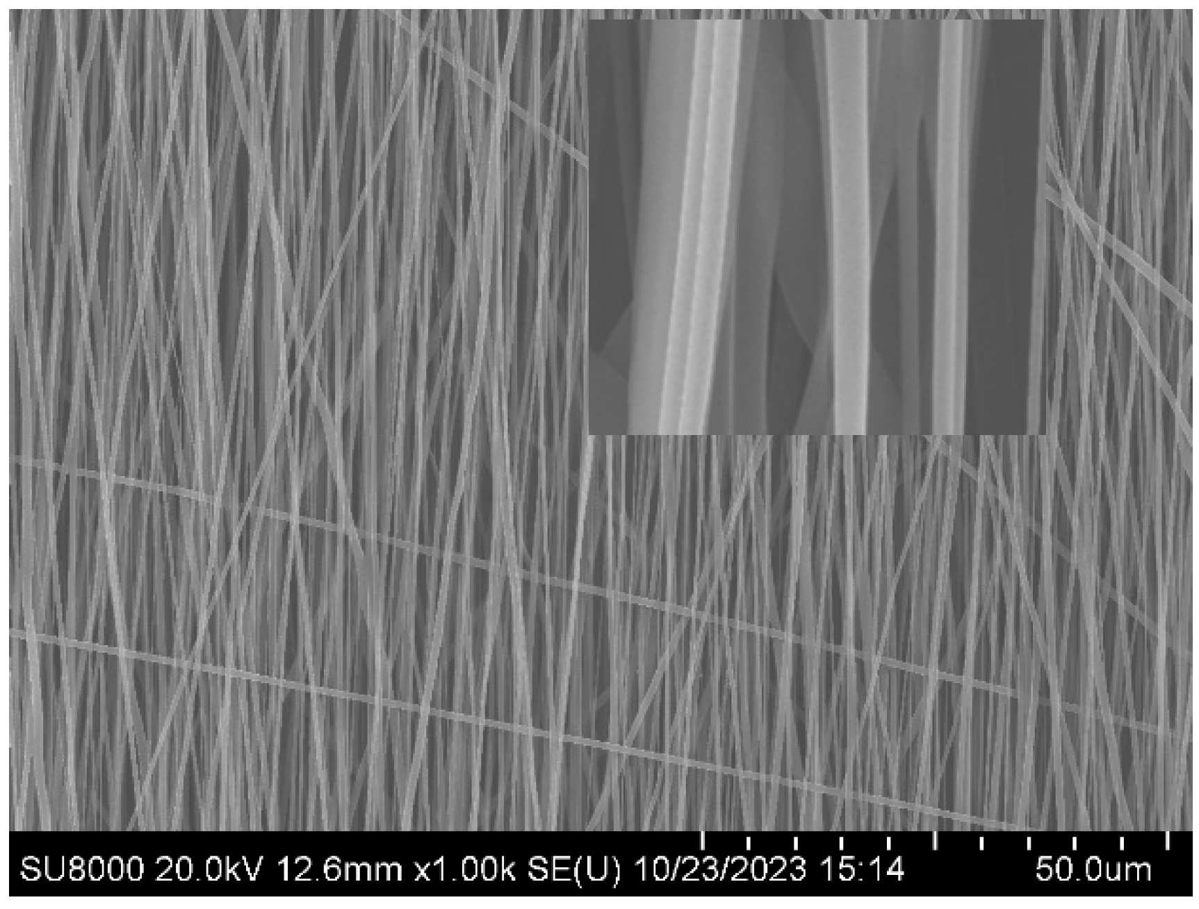
Electrospinning device is mainly composed of high voltage DC power supply, spinning nozzle and collecting device. In this paper, the oriented fibers are collected by a high speed rotating roller. When the rotating speed of the roller is high, high speed air flow is formed on the surface of the roller. When the linear speed of the surface of the roller is consistent with the deposition speed after the jet volatilization, the fibers will be deposited along the rotating direction of the roller to the surface of the roller, forming oriented fibers. As shown in
Figure 1, the oriented PLA fiber prepared at a rotating speed of 3000rmp in a low humidity environment has a smooth surface.
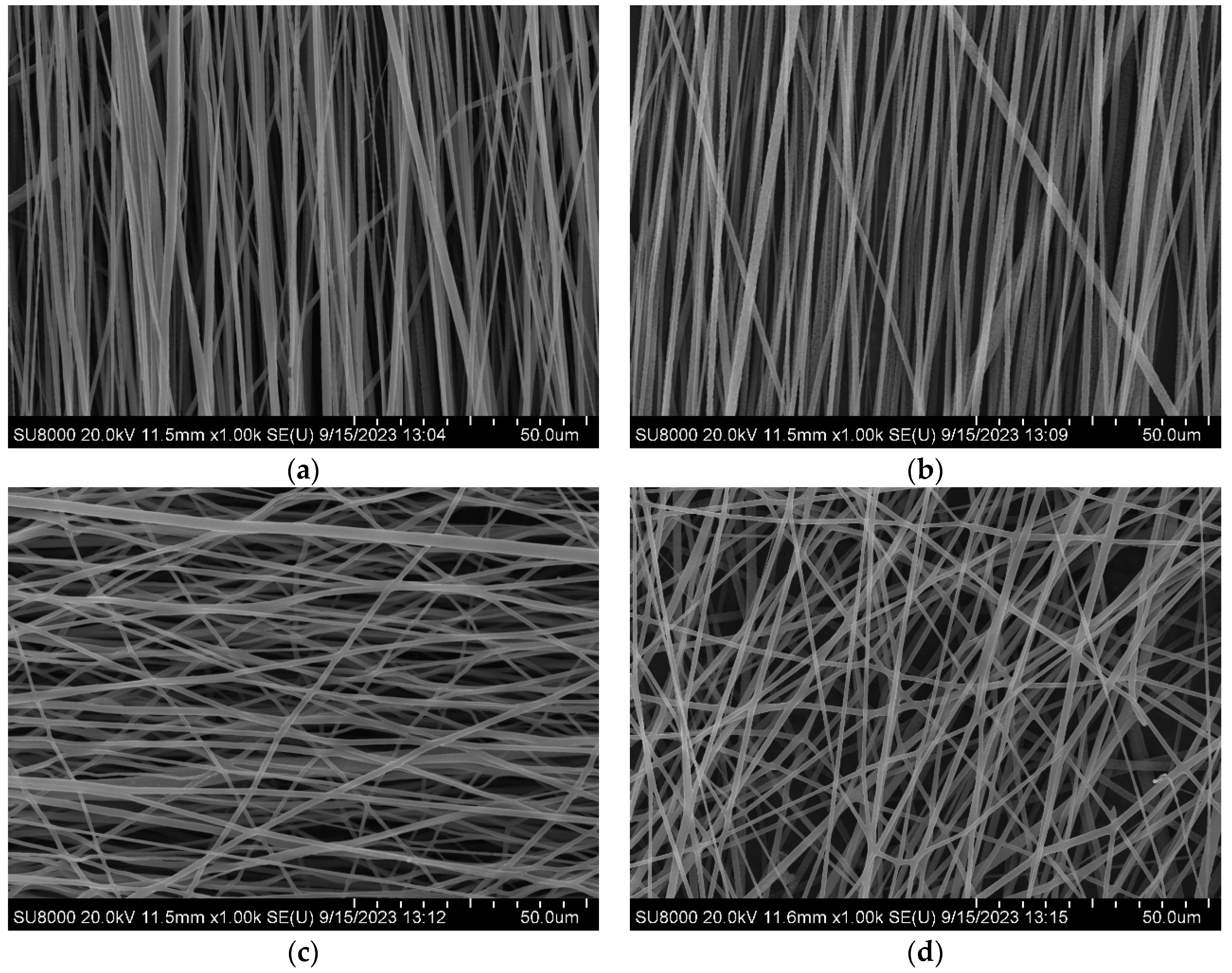
In the process of electrospinning in a high humidity environment, the porous structure is formed on the surface of the fiber through thermal induced phase separation and vapor induced phase separation. When the PLA solution overcomes the surface tension of the solution under the action of high pressure electric field to form a jet, the solvent inside the jet diffuses from the inside out and the surface solvent DCM volatilizes, and the temperature of the jet surface decreases rapidly. Since DCM (DCM volatilization rate: 2750) volatilizes faster than DMF (DMF volatilization rate: slow), thermodynamic instability is triggered and thermal induced phase separation occurs. At this time, the water vapor in the air around the jet will condense on the surface of the jet when it is cold to form water droplets. After the jet is stretched by the electric field, it will be deposited to form fibers. With the evaporation of water droplets and the volatilization of DMF, vapor induced phase separation will occur. Under the joint action of thermal induced phase separation and vapor induced phase separation, PLA solution jet forms polymer rich phase and polymer poor phase. The polymer rich phase solidifies into fiber, while the polymer poor phase forms pore due to solvent volatilization, and finally forms the PLA fiber with a surface porous structure, that is, primary pore structure. And by changing the rotating speed of the roller, the oriented fibers are prepared, and the fibers are scattered to form secondary pore structure, as shown in
Figure 2.
According to
Figure 2, when the rotating speed of the roller is adjusted to 3000rmp, the surface linear speed of the roller is basically consistent with the deposition speed after jet volatilization, and the fibers are highly oriented (Orientation degree: 83.66±7.31°). When the speed is 3500rmp, the fiber thickness is uneven due to excessive stretching (Orientation degree: 87.76±29.61°). When the rotating speed is 2500 and 500rmp, the tensile force on the fiber is insufficient due to the low rotating speed, resulting in poor fiber orientation (Orientation degree: 89.22±51.71°, 92.19±78.38°). Therefore, fibers collected at 3000rmp were selected for follow up experiments.
Along with the preparation of highly oriented fibers, the primary pore structure on the fiber surface also exhibits high orientation (Long axis: 0.31um, Short axis: 0.12um, Axial ratio: 2.63) due to the combined effects of thermally induced phase separation and vapor induced phase separation, which is highly consistent with the fiber's orientation, as shown in
Figure 3. The right image is an enlarged view of the green dashed box position in the left image.
3.2. Correlation between crimped state and crystallinity of PLA fiber
As shown in
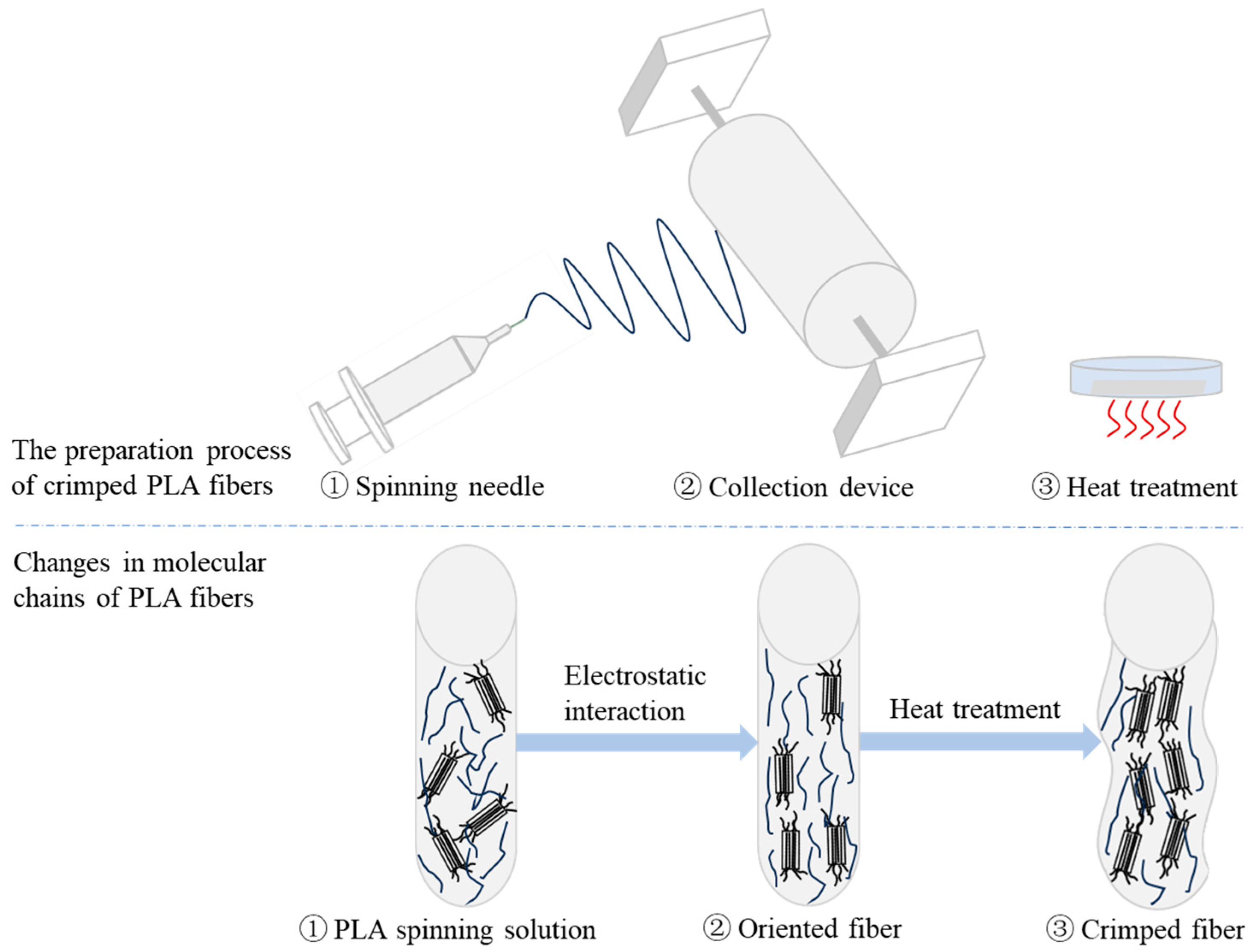
Figure 4, PLA is a semi crystalline polymer with a crystallinity of 10% to 40%. The PLA spinning solution passes through the spinning needle and forms a stable jet under the action of external static electricity. The fibers are stretched and deposited on the collection device to form oriented PLA fibers. After heat treatment, the activity of the molecular chain is accelerated, so that the molecular chain can carry out ordered movement and obtain higher crystallinity. The ordered arrangement of molecular chains forms more chain gaps, so that heat treatment promotes the occurrence of disorientation and forms crimped fibers.
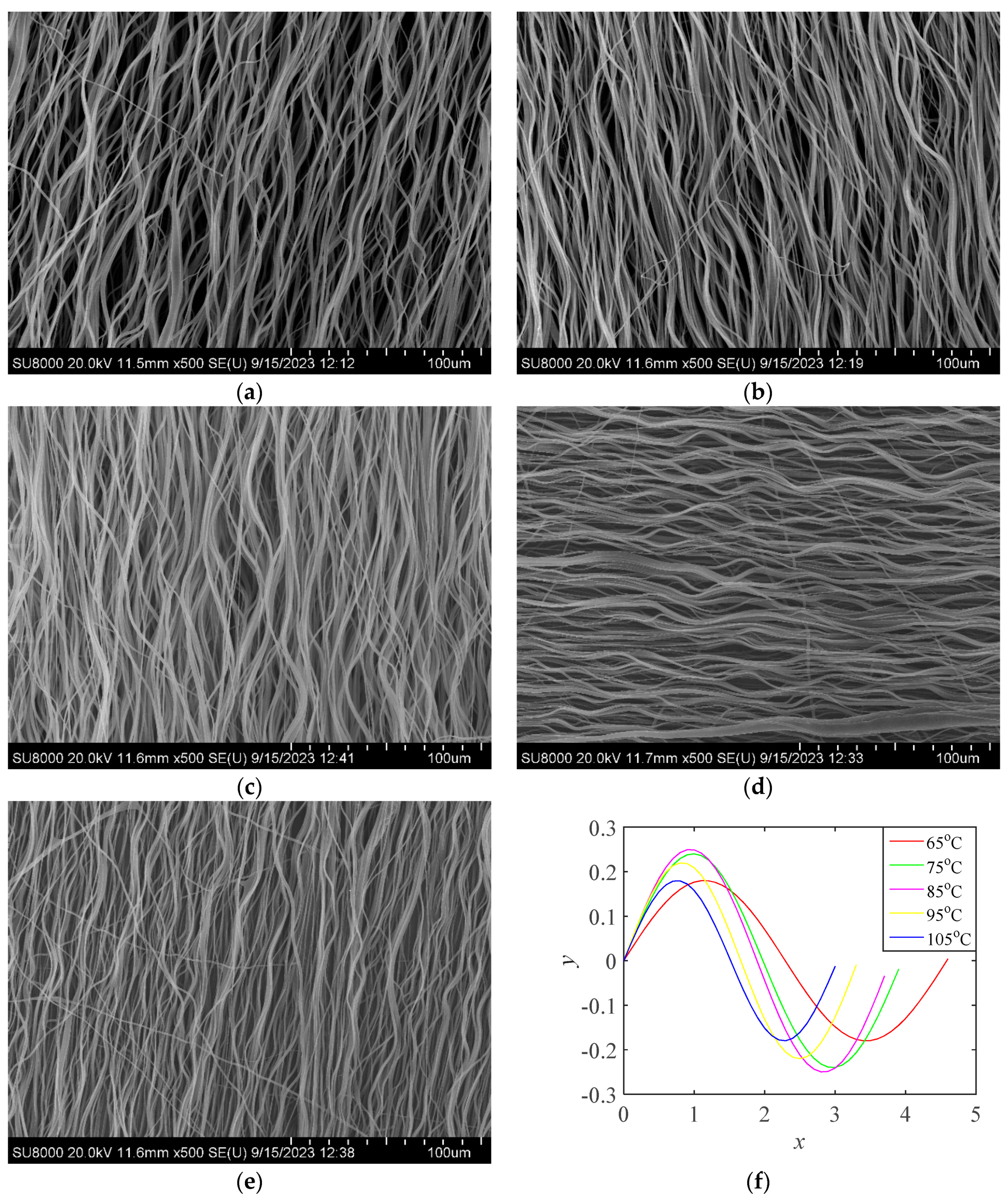
The oriented PLA fibers collected when the rotating speed of the roller was 3000rmp were removed from the roller, covered with aluminum foil, placed in a drying oven, heated at different temperatures for 30min, and then cooled at ambient temperature to form PLA fibers of different crimped states as shown in
Figure 5. Image J was used to calculate the amplitude and angular frequency of PLA fibers in different crimped states, and the crimped state functions as shown in
Figure 5 (f).
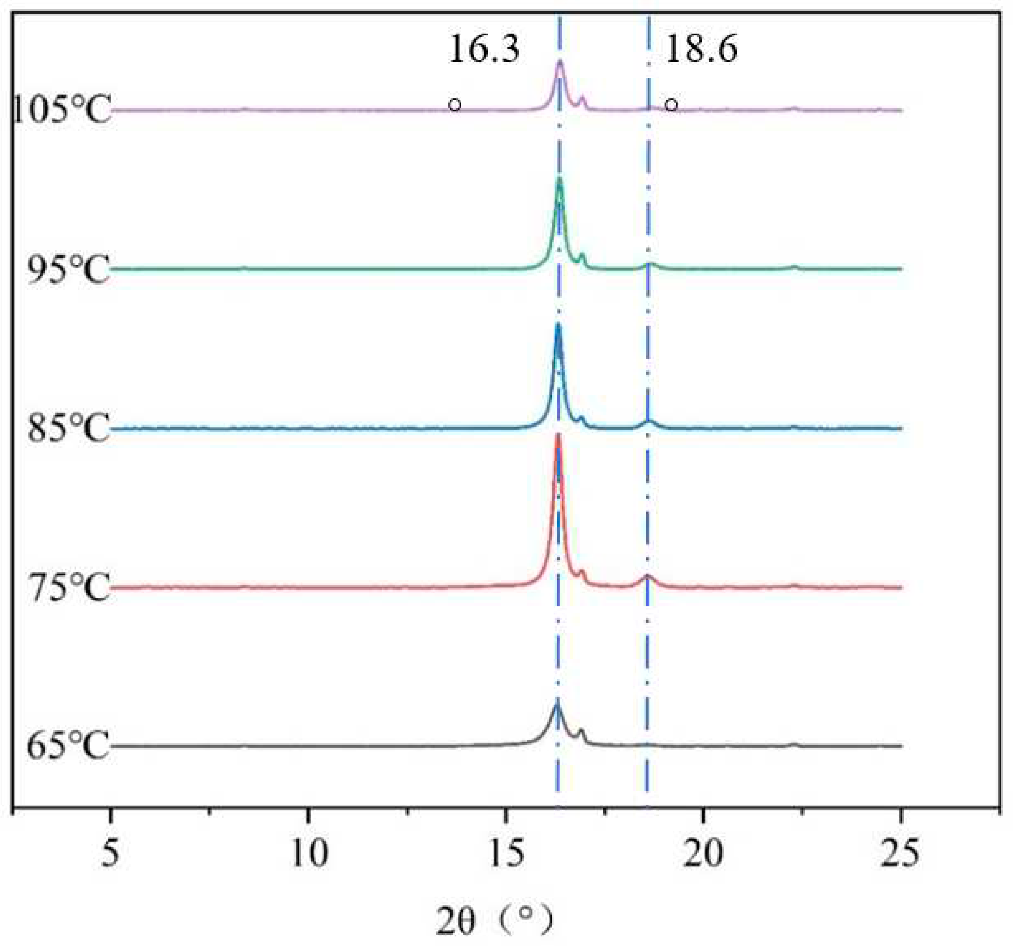
The effect of crystallinity on the crimped PLA fiber was studied by XRD analysis, and the results are shown in
Figure 6. The PLA fiber has strong diffraction peaks at 16.3° and 18.6°, representing (110)/(200) crystal plane and (203) crystal plane reflection [
7]. With the increase of heat treatment temperature, the two diffraction peaks change, and the crystallinity of PLA fiber is effectively increased. Different heat treatment conditions lead to the formation of different crystallinity of PLA fibers, and the formation of different crimped states, as shown in
Table 1.
The heat treatment accelerated the activity of PLA molecular chain and made the molecular chain move in order to obtain higher crystallinity. As the temperature of heat treatment increases, the crystallinity increases. The ordered arrangement of PLA molecular chains forms more chain gaps, so as to promote the occurrence of disorientation by heat treatment, and form PLA fibers in different crimped states. With the increase of the heat treatment temperature to PLA fiber, the crystallinity increases, the amplitude of the crimped state function decreases, and the angular frequency increases. According to formula (2), the Pearson correlation between crimped state and crystallinity of PLA fiber was further obtained.
Pearson correlation coefficient is shown in formula (2):
In formula (2): σX, σY is the standard deviation of X, Y, ,.
The Pearson correlation coefficient ρ of A of crimped state function and crystallinity of PLA fiber is 0.3312, showing a medium correlation. The P value of hypothesis testing is 0.5862, indicating that the null hypothesis cannot be rejected at 90% confidence level. The Pearson correlation coefficient ρ between w of the crimped state function and crystallinity is 0.8775, showing a strong correlation. The P value of the hypothesis testing is 0.0505, indicating that the null hypothesis cannot be rejected at the 95% confidence level.
3.3. Correlation between mechanical properties and crimped state of PLA fiber
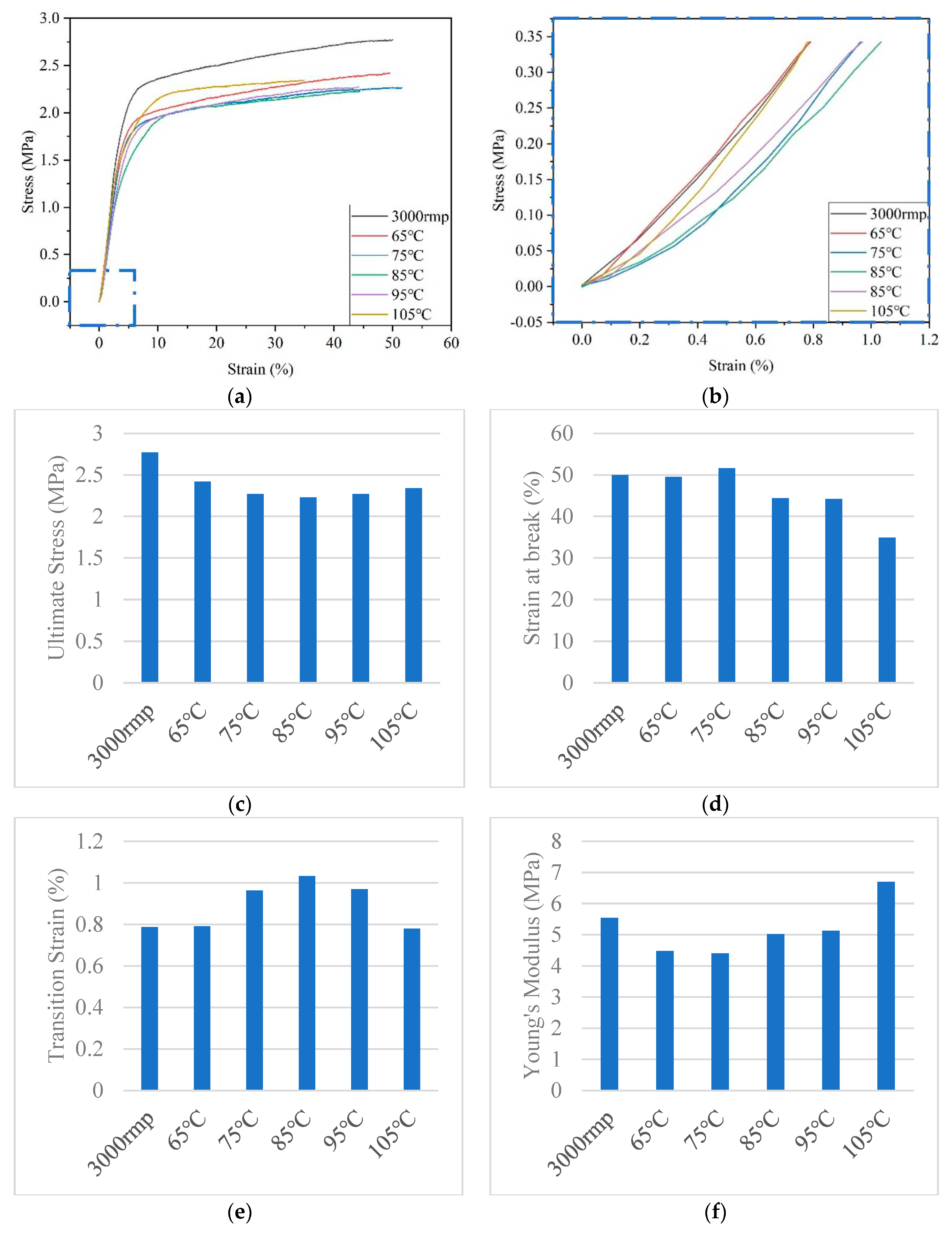
The highly oriented PLA fiber (3000rmp) was prepared by adjusting the rotating speed of the roller, and the crimped state was formed by heat treatment, which mimicked the crimped structure of the elastic membrane and conformed to its nonlinear mechanical properties. According to literature reports, the mechanical properties standard of human coronary arteries is that the stress is 1.4~11.14MPa and the strain is >40%. [
8] The PLA fibers prepared in this paper all meet the standard and have good mechanical properties, which indicates that they have the ability to withstand blood pressure. Moreover, the typical feature of natural blood vessels is the toe region, as shown in
Figure 7 (b) is the toe region enlarged by the blue dotted area of (a). The crimped PLA fiber successfully mimicked the nonlinear mechanical properties of natural blood vessels. Compared with oriented PLA fiber, the stress value, strain value and Young's modulus of crimped PLA fiber are decreased, but the transition strain value is increased (up by 0.25%). With the increase of heat treatment temperature, the stress value first decreases and then increases, the strain value first increases and then decreases, the transition strain value first increases and then decreases, and the Young's modulus shows an increasing trend. It is highly correlated with the amplitude and angular frequency of the crimped state function, as shown in
Table 2.
3.4. Three levels pole structure of PLA fiber
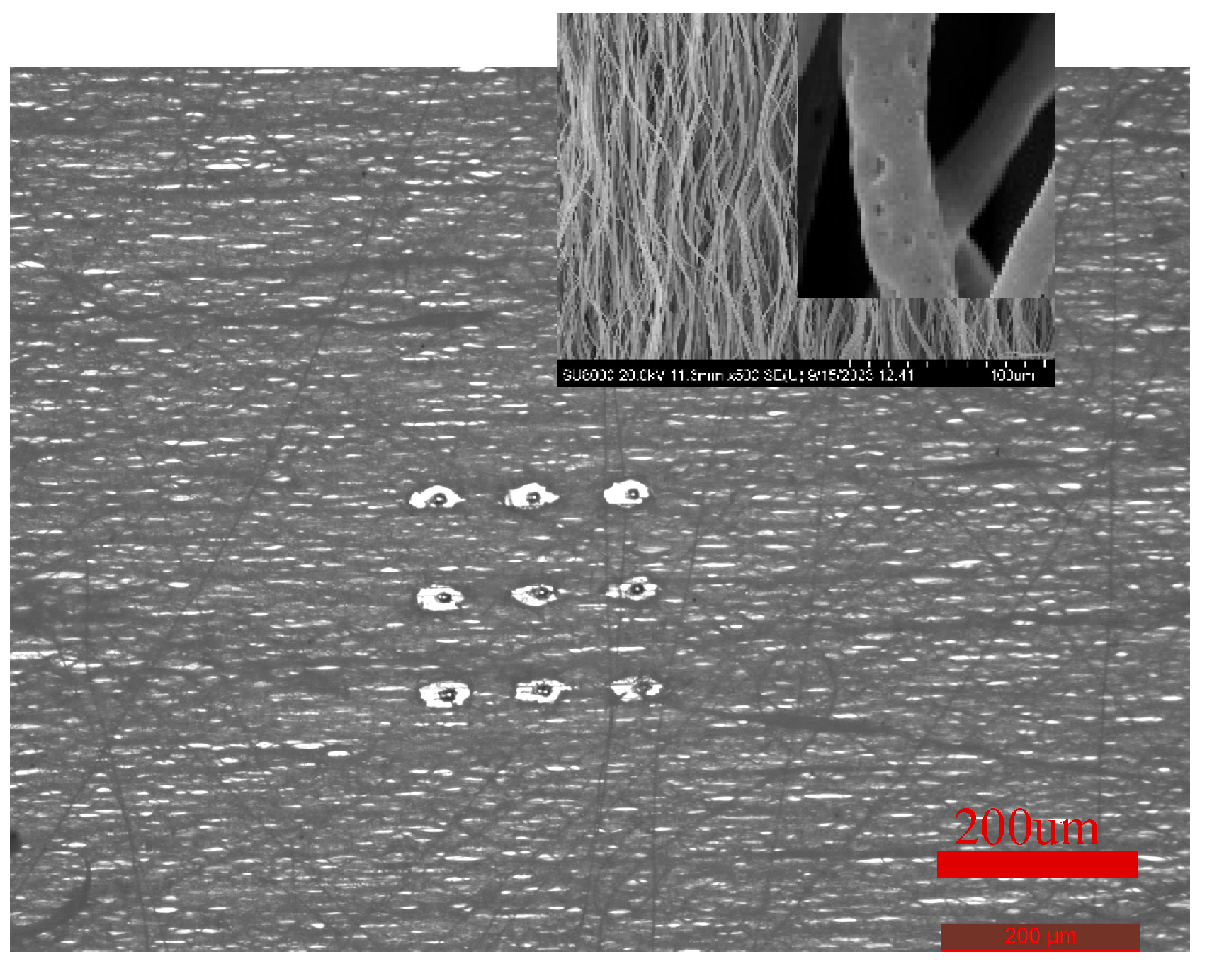
Formation of three levels pore structure: In the process of electrospinning in high humidity environment, primary pore (nm level) structure is formed on the surface of PLA fiber mainly by thermal induced phase separation and vapor induced phase separation; Each fiber is scattered to form secondary pore (smaller um level) structure; After heat treatment, third level pore (larger um level) structure is formed by laser ablation. Finally, a crimped PLA fiber with three levels pore structure is formed, as shown in
Figure 8. Since HUVECs are laterally aligned along the blood flow direction, highly oriented crimped PLA fibers are prepared, and secondary pore structures are naturally formed. In addition, the primary pore structure on the surface of each fiber is conducive to the adhesion and growth of HUVECs. Then the third level pore structure is formed by laser ablation, which is conducive to the migration of HUVECs to other fiber layers and increase the degree of cell infiltrarion. The three levels pore structure of crimped PLA fiber is beneficial to promote rapid endothelialization of blood vessels.
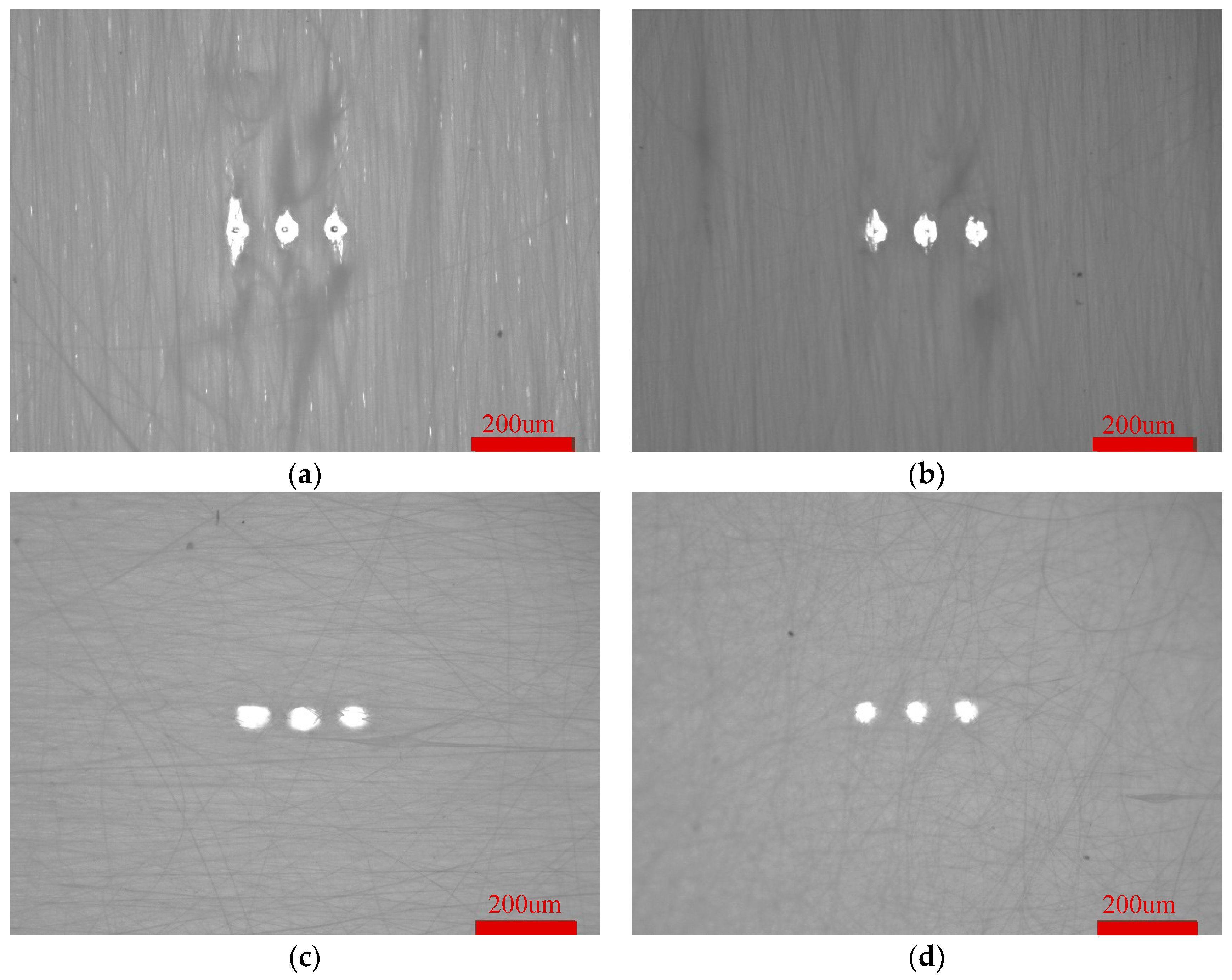
Because the PLA fiber collected when the rotating speed of the roller is 3000rmp has a high orientation, and the PLA fiber has a large thermal conductivity, the thermal conductivity of the fiber is anisotropic when subjected to laser ablation. Compared with the 90° direction of the fiber orientation, the fiber in orientation absorbs more laser energy and forms a oriented third level pore structure, which is highly consistent with the fiber orientation. However, different rotating speeds during fiber collection lead to different fiber orientations, and the orientation of third level pore structure after laser ablation is also different, as shown in
Figure 9. The PLA fibers with different orientations were ablated by 248 excimer laser, and the third level pore structure was formed. Parameters used: voltage is 22kv, frequency is 5Hz, count is 1, energy is 572mJ.
The long and short axis of the third level pore structure of PLA fibers with different oriented states are shown in
Table 3.
As can be seen from
Table 3, as the rotating speed of the roller decreases, the orientation of the fiber becomes worse, and the axial ratio of the third level pore structure becomes smaller. Since the fibers collected at 500rmp are disordered, the axial ratio is close to 1. The third level pore structure changes from anisotropic to isotropic.
The third level pore structure of oriented PLA fiber is anisotropic, while that of crimped PLA fiber is still anisotropic, as shown in
Figure 10. A 3*3 pore array was formed by ablating different crimped PLA fibers with 248 excimer laser. Parameters used: voltage is 21kv, frequency is 5Hz, count is 1, energy is 556mJ.
The long and short axis of the third level pore structure of PLA fibers in different crimped states are shown in
Table 4.
With the increase of heat treatment temperature, the amplitude of crimped fibers increased and then decreased, and the angular frequency increased. The crimped state of the fibers inhibited the heat transfer phenomenon, and the long and short axis of the fibers after heat treatment were smaller than that of the fibers without heat treatment. Moreover, the axial ratio of the fibers after heat treatment is correlated with the crimped state function, and the axial ratio is strongly correlated with A (ρ=-0.9944, P=0.0671, Hypothesis testing: √), the axial ratio is weakly correlated with w (ρ= 0.2069, P=0.8674, Hypothesis testing: √). Among them, the fiber heat treated at 85℃ has a higher amplitude and angular frequency combined, that is, a better degree of crimp. Compared with other fibers after heat treatment, the third level pore structure has the smallest long, short axis and axial ratio, which can better inhibit the heat transfer phenomenon.
In previous studies, the pore formed by laser ablation of fibers are mostly isotropic, but the fibers mimick the highly oriented crimped state of the elastic membrane, and HUVECs grow along the elastic membrane. Therefore, the oriented third level pore structure prepared in this paper is more conducive to the penetration of oriented HUVECs into other fiber layers.
4. The crimped PLA fiber with three levels pore structure affects the cell growth
HUVECs were planted on crimped PLA fiber and crimped PLA fiber with three levels pore structure to study the synergistic effect of different topological structures on the growth of HUVECs.
4.1. HUVECs proliferation analysis
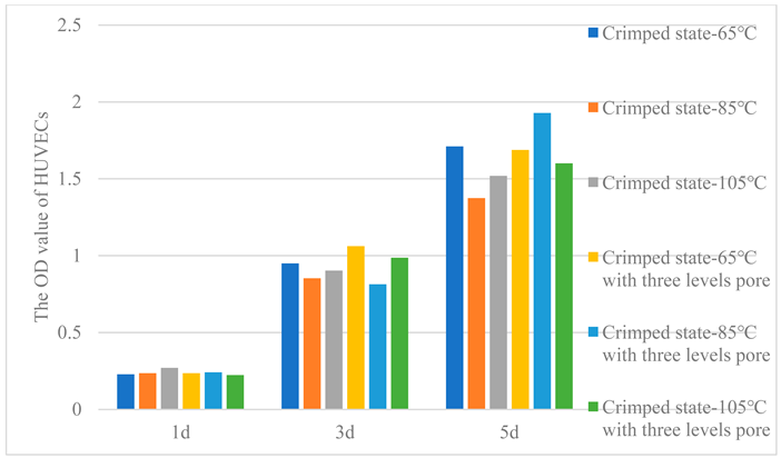
In order to test cell viability, OD values were measured by CCK-8 method, as shown in
Table 5. Cell activity on all fibers increases day by day. After 1d, all fibers showed similar cell viability and achieved good adhesion. After 3d and 5d, the cell viability of crimped PLA fibers -65℃ was higher, the cell viability of crimped PLA fibers -105℃ was lower. The same is true for the crimped PLA fibers with three levels pore structure, except that the crimped PLA fibers -85℃ with three levels pore structure showed the highest cell viability after 5 days.
4.2. HUVECs Morphology observation
The phenomenon that cell morphology follows substrate structure, such as cell elongation when attached to fibrous materials, is known as contact guidance. [
3] As shown in
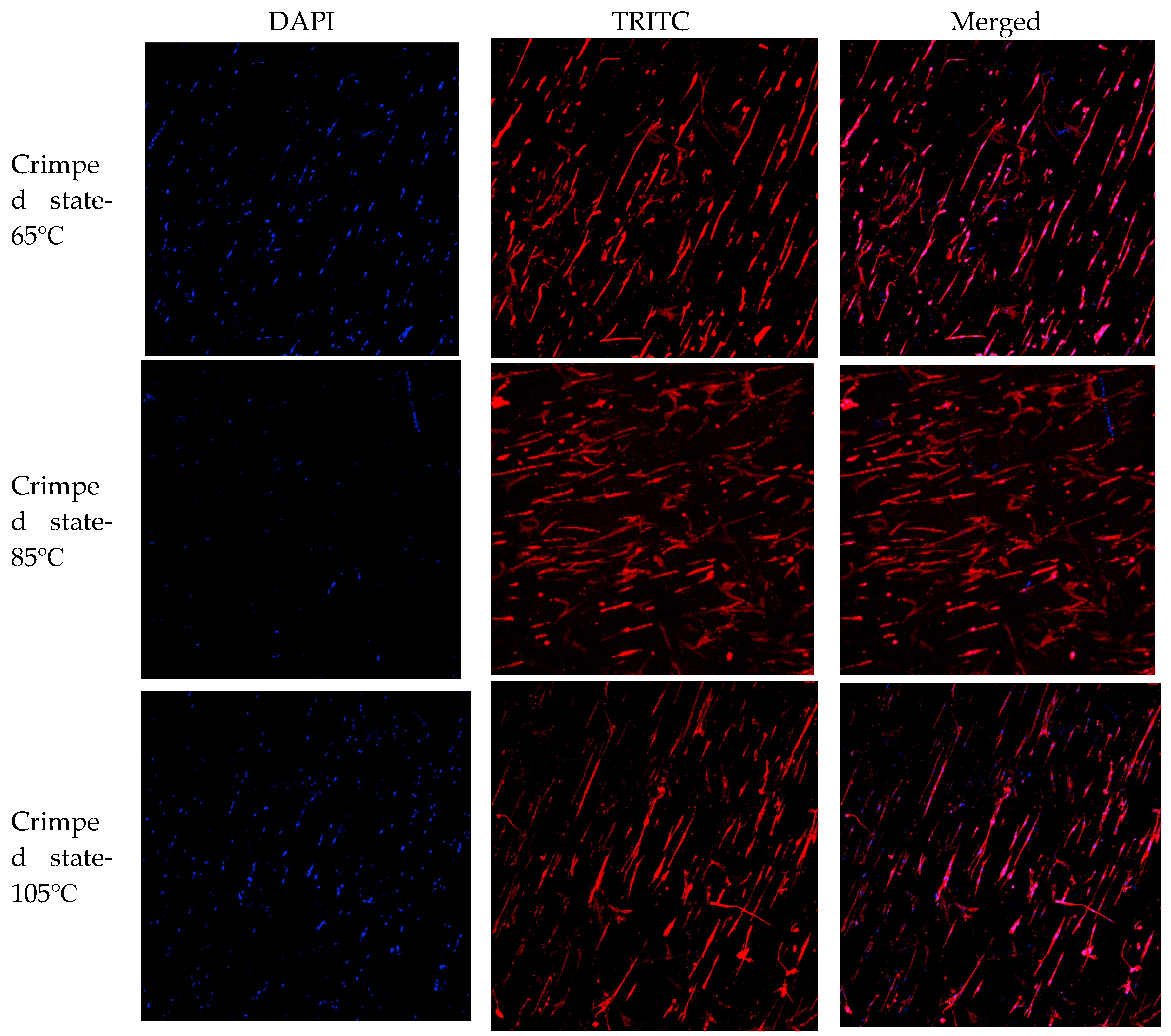
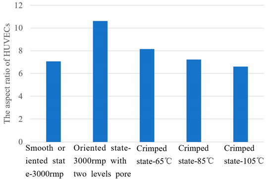
Figure 11, HUVECs grow in highly oriented crimped fibers, forming cell morphology that grows along the fiber orientation. HUVECs expressed more collagen in the form of thin strips. The aspect ratio of HUVECs are shown in
Table 6. The oriented PLA fiber -3000rmp with two levels pore has a higher cell aspect ratio than the cells grown on the smooth oriented PLA fiber -3000rmp. Due to the primary pore structure on the surface of the oriented PLA fiber -3000rmp with two levels pore, larger porosity is formed, which is conducive to cell adhesion and growth [
9]. Close and form a higher cell aspect ratio. With the increase of heat treatment temperature, crimped fibers were formed, and the cell aspect ratio decreased at static state, showing a weak correlation with the amplitude of the crimped state function (ρ=-0.1015, P=0.9353, Typothesis testing: √), and a strong correlation with the angular frequency of crimped state function (ρ=-0.9791, P=0.1303, Typothesis testing: √). This indicated that when the fibers were subjected to blood flow pressure, as the fibers stretched, the cells had a higher aspect ratio and were aligned along the fiber orientation than the oriented PLA fibers, and formed a good growth morphology. Therefore, when the crimped PLA fiber mimicks the crimped structure and nonlinear mechanical properties of the elastic membrane, it is more conducive to the growth of HUVECs and promote the rapid endothelialization of blood vessels.
After inoculating HUVECs on the crimped PLA fibers with three levels pore structure for 3 days, the morphology was observed. HUVECs adhered to the periphery of three levels pore structures of different sizes and aligned laterally, as shown in
Figure 12. Laser ablation can form cell patterned growth in high precision, repeatable, ordered and adjustable oriented micrometer pore arrays. In addition, HUVECs can migrate to other fiber layers through the third level pore structure, increase the degree of cell infiltrarion, realize inward growth, and promote rapid endothelization of blood vessels.
5. Summary
The crimped PLA fiber with three levels pore structure prepared in this paper not only mimicks the crimped structure of the elastic membrane of blood vessel wall, but also has nonlinear mechanical properties. The three levels pore structure also enhanced cell adhesion and proliferation, exhibited good growth morphology and formed patterned growth, improved cell infiltrarion, realized ingrowth, effectively promoted rapid endothallization of blood vessels, and reduced the occurrence of thrombosis, providing theoretical and practical reference for the design and development of small diameter tissue engineering blood vessels. However, in vitro cell experiments still have certain limitations, the experimental environment is very different from in vivo. So subsequent animal experiments should also be done.
References
- Shujie Yan, Brett Napiwocki, et al. Wavy small diameter vascular graft made of eggshell membrane and thermoplastic polyurethane[J]. Materials Science & Engineering C, 2020, 107, 110311. [CrossRef]
- 于成龙. 双维度仿生血管基底膜的构建及其在小口径组织工程血管中的应用[D]. 东华大学, 2022.
- Grace Chao P H, Hsu H Y, Tseng H Y. Electrospun microcrimped fibers with nonlinear mechanical properties enhance ligament fibroblast phenotype[J]. Biofabrication, 2014, 6(3): 035008. [CrossRef]
- Chen Z, Zhou B, Wang X, et al. Synergistic effects of mechanical stimulation and crimped topography to stimulate natural collagen development for tendon engineering[J]. Acta biomaterialia, 2022, 145: 297-315. [CrossRef]
- Lee B L P, Jeon H, Wang A, Yan Z, Yu J, Grigoropoulos C, Li S. Femtosecond laser ablation enhances cell infiltration into three dimensional electrospun scaffolds[J]. Acta Biomaterialia, 2012, 8(7), 2648–2658. [CrossRef]
- Mccullen S D, Gittard S D, Miller P R, et al. Laser Ablation Imparts Controlled Micro Scale Pores in Electrospun Scaffolds for Tissue Engineering Applications[J]. Annals of Biomedical Engineering, 2011, 39(12): 3021. [CrossRef]
- Li Y, Lim C T, Kotaki M. Study on structural and mechanical properties of porous PLA nanofibers electrospun by channel based electrospinning system[J]. Polymer, 2015, 56: 572-580. [CrossRef]
- 李玉梅. 静电纺聚己内酯复合纤维在血管组织工程中的潜在应用[D]. 吉林大学, 2019.
- Jain P, Rimal R, Möller M, Singh S. Topographical influence of electrospun basement membrane mimics on formation of cellular monolayer[J]. Scientific Reports, 2023. [CrossRef]
Figure 1.
Smooth Oriented PLA fiber-3000rmp.
Figure 1.
Smooth Oriented PLA fiber-3000rmp.
Figure 2.
Oriented PLA fiber with secondary pore (a) 3500rmp (b) 3000rmp (c) 2500rmp (d) 500rmp.
Figure 2.
Oriented PLA fiber with secondary pore (a) 3500rmp (b) 3000rmp (c) 2500rmp (d) 500rmp.
Figure 3.
Highly oriented PLA fibers with primary pore structure.
Figure 3.
Highly oriented PLA fibers with primary pore structure.
Figure 4.
Preparation principle of crimped PLA fiber.
Figure 4.
Preparation principle of crimped PLA fiber.
Figure 5.
Crimped PLA fiber (a) 65℃-30min (b) 75℃-30min (c) 85℃-30min (d) 95℃-30min (e) 105℃-30min (f) Crimped state function.
Figure 5.
Crimped PLA fiber (a) 65℃-30min (b) 75℃-30min (c) 85℃-30min (d) 95℃-30min (e) 105℃-30min (f) Crimped state function.
Figure 6.
XRD analysis of crimped PLA fiber.
Figure 6.
XRD analysis of crimped PLA fiber.
Figure 7.
Mechanical properties of oriented and crimped PLA fiber (a) all regions (b) toe region (c) stress value (d) strain value (e) transition strain value (f) Young's modulus.
Figure 7.
Mechanical properties of oriented and crimped PLA fiber (a) all regions (b) toe region (c) stress value (d) strain value (e) transition strain value (f) Young's modulus.
Figure 8.
Crimped PLA fiber with three levels pore.
Figure 8.
Crimped PLA fiber with three levels pore.
Figure 9.
Oriented PLA fiber with three levels pore (a) 3500rmp (b) 3000rmp (c) 2500rmp (d) 500rmp.
Figure 9.
Oriented PLA fiber with three levels pore (a) 3500rmp (b) 3000rmp (c) 2500rmp (d) 500rmp.
Figure 10.
Crimped PLA fiber with three levels pore (a) 65℃ (b) 85℃ (c) 105℃.
Figure 10.
Crimped PLA fiber with three levels pore (a) 65℃ (b) 85℃ (c) 105℃.
Figure 11.
Growth morphology of HUVECs in crimped PLA fiber.
Figure 11.
Growth morphology of HUVECs in crimped PLA fiber.
Figure 12.
Patterned growth of HUVECs in crimped PLA fiber with three levels pore (a) 65℃ (b) 85℃ (c) 105℃.
Figure 12.
Patterned growth of HUVECs in crimped PLA fiber with three levels pore (a) 65℃ (b) 85℃ (c) 105℃.
Table 1.
Correlation between crimped state and crystallinity of PLA fiber.
Table 1.
Correlation between crimped state and crystallinity of PLA fiber.
| Number |
Heat treatment |
Crystallinity |
A of crimped state function |
w of crimped state function |
| 1 |
65℃,30min |
50.3% |
1.82 |
0.14 |
| 2 |
75℃,30min |
71.5% |
2.40 |
0.16 |
| 3 |
85℃,30min |
82.3% |
2.65 |
0.17 |
| 4 |
95℃,30min |
82.4% |
2.18 |
0.19 |
| 5 |
105℃,30min |
86.5% |
1.80 |
0.21 |
Table 2.
Correlation between mechanical properties and crimped state of PLA fiber.
Table 2.
Correlation between mechanical properties and crimped state of PLA fiber.
| Number |
Variable |
Pearson correlation coefficient () |
P value |
Correlation |
Hypothesis testing |
| 1 |
Ultimate Stress and A |
-0.8828 |
0.0473 |
Strong correlation |
× |
| 2 |
Ultimate Stress and w |
-0.2984 |
0.6257 |
Weak correlation |
√ |
| 3 |
Strain at break and A |
0.3528 |
0.5603 |
Medium correlation |
√ |
| 4 |
Strain at break and w |
-0.8882 |
0.0441 |
Strong correlation |
× |
| 5 |
Transition Strain and A |
0.9574 |
0.0105 |
Strong correlation |
√ |
| 6 |
Transition Strain and w |
-0.0750 |
0.9045 |
No correlation |
√ |
| 7 |
Young’s Modulus and A |
-0.4207 |
0.4806 |
Medium correlation |
√ |
| 8 |
Young’s Modulus and w |
0.8920 |
0.0419 |
Strong correlation |
× |
Table 3.
The long and short axis of the third level pore of PLA fibers with different oriented states.
Table 3.
The long and short axis of the third level pore of PLA fibers with different oriented states.
| Roller speed (rmp) |
Long axis (um) |
Short axis (um) |
Axial ratio |
| 3500 |
105 |
51 |
2.05 |
| 3000 |
80 |
50 |
1.61 |
| 2500 |
64 |
46 |
1.41 |
| 500 |
44 |
43 |
1.01 |
Table 4.
The long and short axis of the third level pore of PLA fibers in different crimped states.
Table 4.
The long and short axis of the third level pore of PLA fibers in different crimped states.
| Heat treatment temperature (°C) |
Long axis (um) |
Short axis (um) |
Axial ratio |
A of crimped state function |
w of crimped state function |
| -- |
80 |
50 |
1.61 |
-- |
-- |
| 65 |
61 |
30 |
2.05 |
1.82 |
0.14 |
| 85 |
49 |
27 |
1.86 |
2.65 |
0.17 |
| 105 |
59 |
28 |
2.08 |
1.80 |
0.21 |
Table 5.
The OD value of HUVECs.
Table 5.
The OD value of HUVECs.
Table 6.
The aspect ratio of HUVECs.
Table 6.
The aspect ratio of HUVECs.
|
Disclaimer/Publisher’s Note: The statements, opinions and data contained in all publications are solely those of the individual author(s) and contributor(s) and not of MDPI and/or the editor(s). MDPI and/or the editor(s) disclaim responsibility for any injury to people or property resulting from any ideas, methods, instructions or products referred to in the content. |
© 2024 by the authors. Licensee MDPI, Basel, Switzerland. This article is an open access article distributed under the terms and conditions of the Creative Commons Attribution (CC BY) license (https://creativecommons.org/licenses/by/4.0/).
