1. Introduction
Three-dimensional (3D) time-of-flight (TOF) magnetic resonance angiography (MRA) without contrast media is a valuable non-invasive tool for evaluating intracranial aneurysms following flow diverter treatment [
1]. However, it is limited by susceptibility artefacts that may obscure the visibility of the parent vessel lumen [
1,
2,
3,
4].
Silent MRA is a sequence that GE Healthcare has just recently introduced. This technique combines a zero echo time (ZTE) 3D radial sampling with an arterial spin-labeling preparation module [
5]. Arterial spin labeling preparation is applied at the neck, tagging the flowing blood towards entering the imaging region, allowing to visualize the flowing blood. Prior to the labeling pulse, native images (unlabeled images) are made. After the labeling pulse, labeled images are acquired. Images of the flowing blood are produced by subtracting labeled images from native images in a similar fashion as the digital subtraction angiography.
ZTE imaging can diminish magnetic susceptibility and minimize phase dispersion of the labeled blood flow signal resulting in reduction of metallic artefacts from stents or other metallic objects, such as coils, enabling visualization of the lumen [
6,
7,
8,
9,
10]. In studies investigating the intracranial stents including flow diverters, the visualization ability of silent MRA was found to be superior to that of TOF MRA [
6,
7,
8,
9,
10].
A deep learning-based (DL) denoising and deranging algorithm was recently introduced to the market by GE HealthCare as AIR
TM Recon DL (GE HealthCare, Waukesha, WI) including a deep convolutional neural network to support the reconstruction process of raw data, thus increasing the signal-to-noise ratio and producing clean and sharp images [
11]. The purpose of this study was to compare the performance of several non-contrast enhanced MRA approaches in lumen visibility in flow models using the Surpass Evolve flow diverter.
This is the first in vitro study evaluating the abilities of deep learning-based silent MRA sequence in imaging of a flow diverter stent.
2. Materials and Methods
2.1. Flow Diverter
The Surpass Evolve (SE, Stryker Neurovascular, Kalamazoo, MI, USA) is a flow diverter stent used in endovascular embolization of intracranial aneurysms. It consists of 64 braided cobalt chromium wires interwoven with platinum-tungsten wires to improve visibility under fluoroscopy.
2.2. Experimental Setup
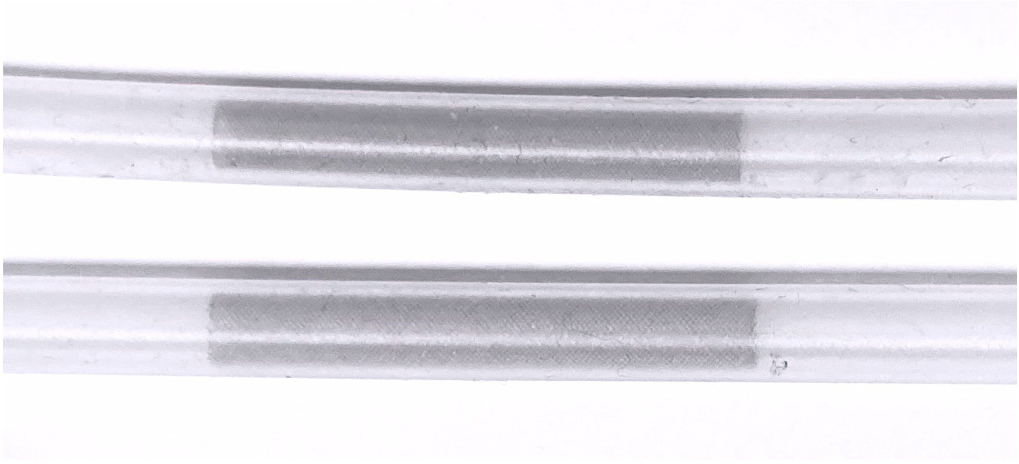
Under fluoroscopic guidance, two stents of different sizes (width x length) (4.5 x 25 mm
2 and 5 x 20 mm
2) were implanted in two silicone tubes with an inner diameter of 4.4 mm (
Figure 1). To confirm optimal wall apposition of the stents, contrast enhanced flat panel CT was performed.
Three boxes were created for each scan set. The silicone tubes (one without a stent and two with each stent) were placed in three separate transparent plastic boxes in a straight position for the first series of scans, then in two different curve configurations (obtuse angle curve (C1)) and (almost a) right angle curve (C2)) for the second and third series of scans.
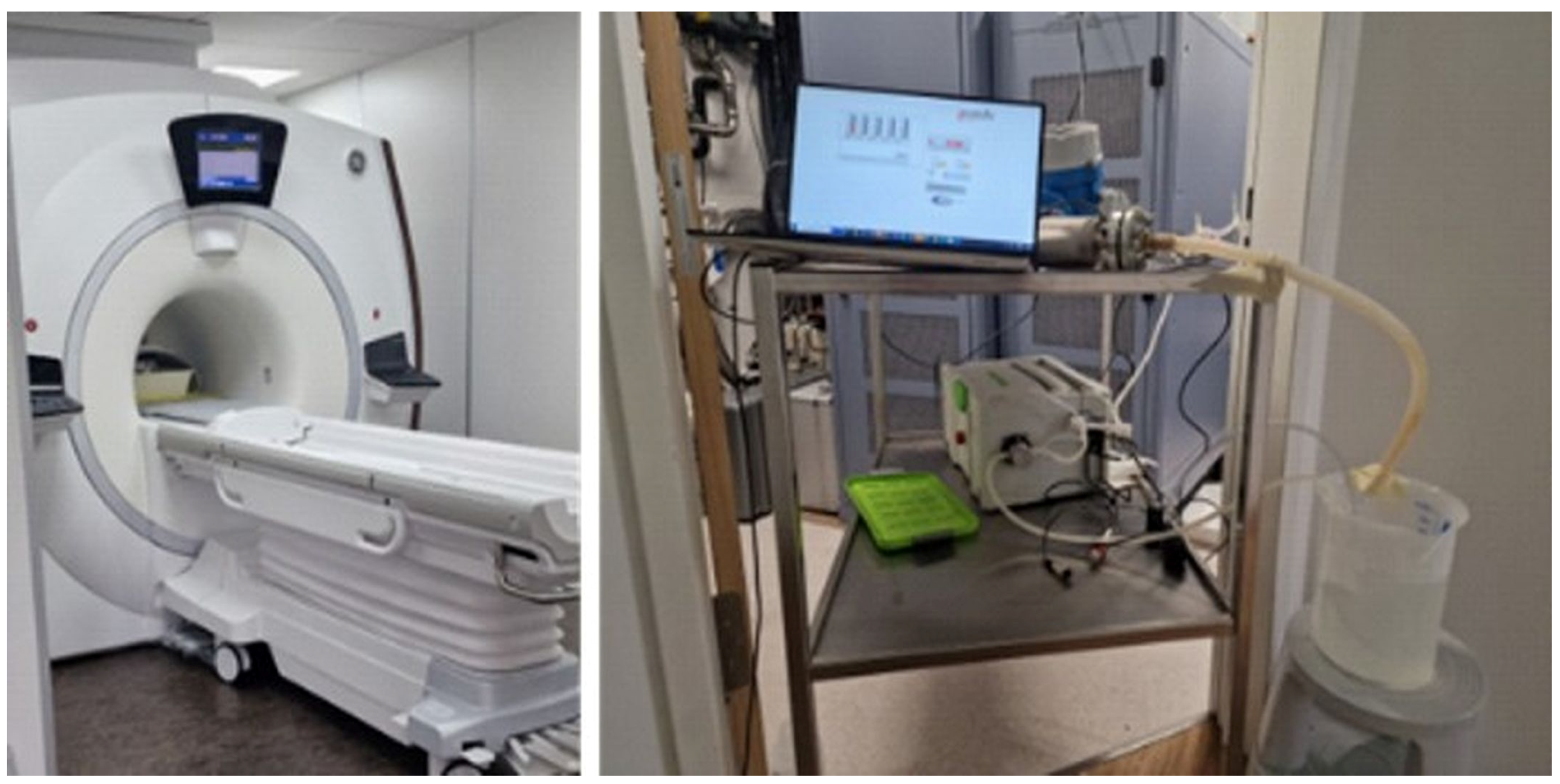
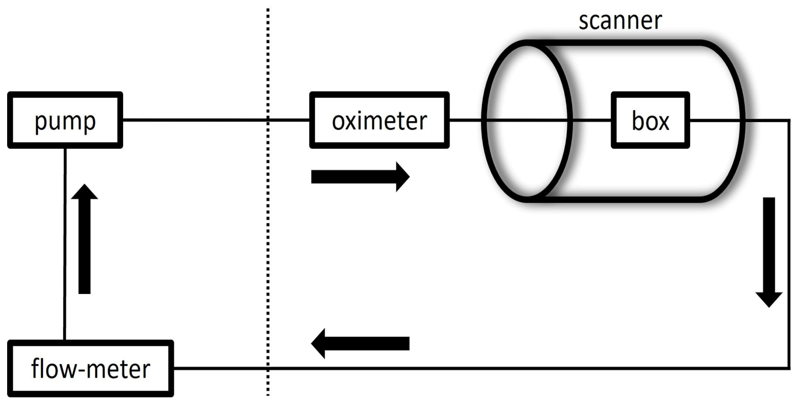
The water-filled boxes and silicone tubes were connected to a pulsatile flow pump to construct a flow loop. Flowcon1000 v1.5 software (αCandis GmbH, Pforzheim, Germany) was utilized to control the pump.
T1 relaxation time of the circulating water was reduced by adding gadolinium contrast material, 0.7 mmol of Magnevist (Bayer Vital GmbH, Germany) in the closed water circuit of about 7 liters to simulate the T1 characteristics of the blood (T1 ≈ 1.6 s). A Coriolis flowmeter (PROMASS 83F08, Endress+Hauser GmbH, Germany) to measure a ground-truth net flow value with a precision of ±0.5ml/s, was connected after the outlet of the models close to the pump.
The construct was then positioned in the center of the body coil with the longitudinal axis of the tubes parallel to the main magnetic field. The acquisitions were conducted under pulsatile flow conditions (60 beats/min). For confirmation of pulsatility of the flow and to trigger the sequences, a pulse oximeter was attached on the silicone tube before entering the box. The mean flow rate was set to 400 ml/min, as determined by the flowmeter, simulating flow conditions in the internal carotid artery.
2.3. MR Imaging
MR images were obtained on a GE HealthCare 3.0T MRI scanner (Discovery MR750w, GE Healthcare, Milwaukee, WI, USA) using the coils integrated in the scanner table. At first, we obtained 3D TOF MRA with parameters as follows: spoiled gradient-echo sequence with TR/TE/FA, 24 msec/3.4 msec/15°; FOV/acq matrix, 200 mm x 200 mm/ 200 x 200; acq slice thickness, 1 mm, reconstructed voxel size, 0.5x0.78x0.78 mm3; ARC=2. Vein saturation slab was not used. Number of slices was 150. Scan time was 2 minutes and 40 seconds.
The parameters for silent MRA were as follows: ASL-prep 3D radial ZTE sequence with TR/TE/FA, 3.077 msec/0.028 msec/5°; FOV/acq matrix, 180 mm x 180 mm/ 180 x 180; reconstructed voxel size, 1x0.7x0.7mm3. Number of slices was 120. Scan time was 4 minutes and 12 seconds.
2.4. Image Post-Processing and Analysis
A labeled database of 10000 image pairs was used to train a DL model in a supervised manner [
11]. The model is designed to remove noise seen in ZTE scans and improve the perception of image resolution. This trained model was used to reconstruct silent MRA raw data, with the acquired data being processed through both the conventional approach and the DL based approach.
ImageJ Version 1.54 (US National Institutes of Health, Bethesda, Md., USA) was used for image analysis. Signal intensities inside the tubes and of the background were measured. Measurements were done in the plane perpendicular to the course of the tubes at three locations along the segments with stents (both stent ends and in the middle) and two areas outside of the stent (5 mm proximal and distal to the stent ends) using circular regions of interest (ROI). The mean value of measurements from stent-free areas represented the vessel SI (SIv) and from stent segments represented the in-stent SI (SIin-stent).
The signal intensity of the background (SIbg) was measured in the plane through the midsection of the stents. The ratio of SIin-stent to SIbg and of SIin-stent to SIv were calculated.
3. Results
The SI
in-stent/SI
bg and SI
in-stent/SI
v ratio were higher on both silent MRA scans with and without DL-based reconstructions than on TOF images in models with straight and C1 configuration. However, this trend could not be consistently seen on images in models with C2 configuration. SI
in-stent/SI
bg showed the strength of the DL denoising algorithm in minimizing the background noise in all configurations and with and without stent (
Table 1 and
Table 2).
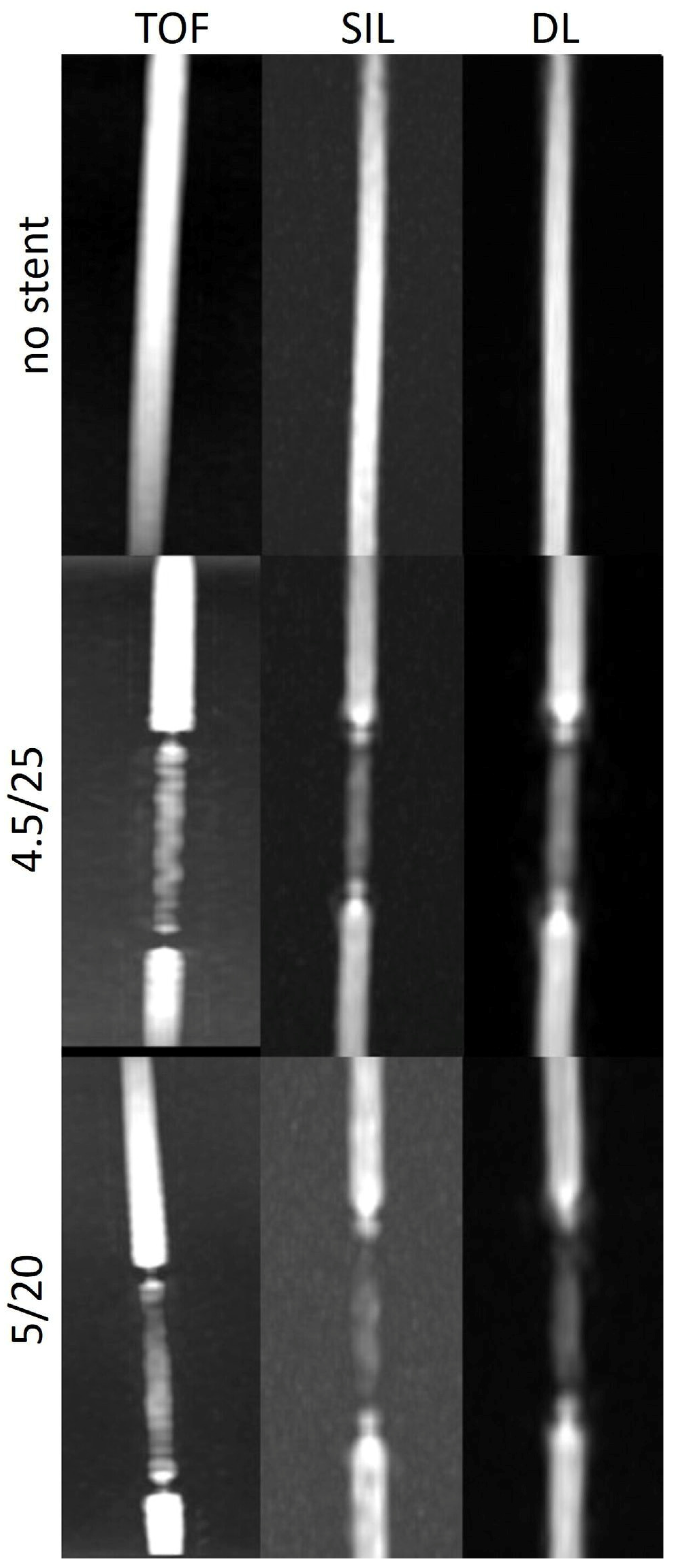
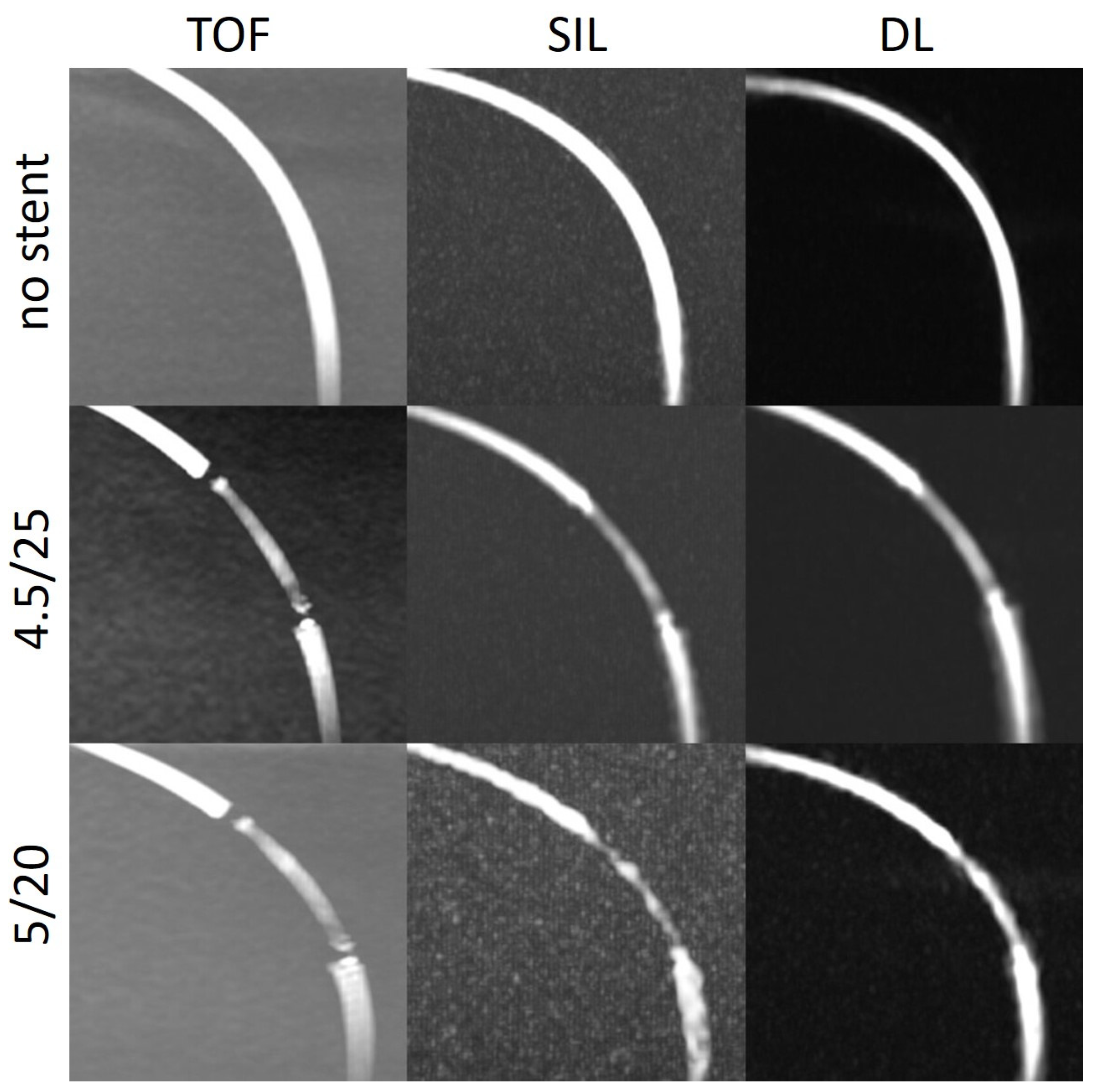
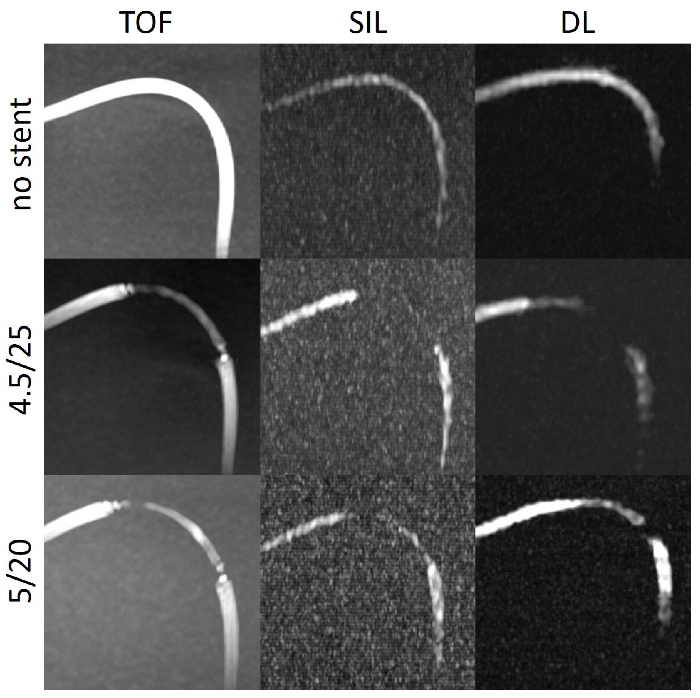
The stent tips created severe artefacts on TOF, which could not be observed on silent scans (
Figure 4,
Figure 5 and
Figure 6).
4. Discussion
Our research sought to assess the efficacy of different non-contrast enhanced MR angiography methods in evaluation of stent lumen in vascular flow models carrying the Surpass Evolve flow diverter. In models with varied curves and two different stent sizes, intraluminal SIs were measured in the areas with and without stent.
The SIin-stent/SIbg and SIin-stent/SIv ratios were consistently higher on silent scans and DL-based reconstructions than on TOF except in models with a tighter curve. The stent tips caused severe artefacts on TOF compared to silent MRA.
One of the advantages of the silent MRA is reduction of metallic artefacts from stents or other metallic objects, such as coils or surgical clips due to the ZTE imaging, enabling better visualization of blood flow [
5,
6,
7,
8,
9,
10]. Additionally, the negative effect of the turbulent flow observed in TOF MRA may diminish [
5,
6,
7,
8,
9,
10]. In studies evaluating intracranial laser-cut and braided stents, the visualization capability of silent MRA was found to be superior to that of 3D TOF MRA. In addition, silent MRA was able to reveal neck remnants of coiled aneurysms with greater accuracy than TOF. Silent MRA could thus identify aneurysm occlusion more effectively than TOF. Moreover, silent MRA demonstrated superior visualization of aneurysms treated with a flow diverter stent regardless of aneurysm location, degree of in-stent stenosis, and presence or absence of additional coiling [
5,
6,
7,
8,
9,
10].
Further advantages of silent MRA are insensitivity to motion artefacts due to radial sampling and elimination of noise increasing patient comfort resulting in less anxiety in the scanner with better compliance [
12,
13].
However, as Holdsworth et al. [
5] also stated, silent MRA has some intrinsic problems, mainly due to the known limitations of arterial spin labeling technique in regions of slow flow. In their study, they observed poorly defined and smaller caliber vessels suggesting wall irregularities on silent scans, most probably related to the slower flow along the vessel wall compared to the center. Second issue, they pointed out, was the attenuation or absence of patent vessels. In another study, in five of 27 silent intracranial MRAs, distal vessels could not be evaluated due to the poor inflow [
14]. Therefore, caution was advised, since it could mimic the vascular pathologies.
We observed this finding especially in the models with a tighter curve (C2) (
Figure 6). In the model without stent, the intraluminal signal was overall very poor but poorer in the regions where the tube enters and exits the box. In the models with stents, there was almost no signal in the stent. One explanation for that could be slow flow caused by a kinking or stenoses of the silicone tubes at the entry or exit points of the boxes. Another explanation for the poorer results in the C2 models could be that the labelling location, which was placed 10 cm below the imaging volume, tagged less flowing water in the model with respect to the other models, decreasing the signal within the tube.
DL-based denoising algorithm could partially overcome the limitations of silent MRA scan in these regions. In most of the models, the SI
in-stent (not shown) was higher after DL reconstruction compared with the silent MRA scans. DL could enhance the stent signal and at some points restore the signal loss, which could especially be appreciated in models with a tighter curve (
Figure 6). The silent MRA scans in this study use a self-calibrated coil sensitivity method that can lead to sub-optimal coil sensitivity estimates, especially in regions with very low signal intensities. The use of a dedicated external calibration is likely to improve performance and will be explored in future work.
The last thing to discuss would be the absence of artefacts at the stent tips on silent MRA compared to the severe artefacts seen on TOF sequences in the same regions.
More pronounced signal loss at the ends of stents is typically observed with stents that contain additional radiopaque markers at their tips, which raises the quantity of metal and increases susceptibility and radiofrequency artefacts [
4,
15]. However, Surpass Evolve doesn’t have extra radiopaque markers at its tips. Moreover, this phenomenon was not related to the configuration of the curve, as it has been demonstrated that artefacts may increase as the angle between the magnetic field and stent orientation grows [
16].
The turbulent flow pattern seen at the edges of the stent may explain the focal signal loss on TOF. Additionally, exposed loop wires at the stent tips can exacerbate eddy currents resulting in increased radiofrequency shielding artefacts [
17].
The reported better background signal suppression and visualization of blood flow in regions with turbulent pattern [
18] with silent MR imaging technique could explain the absence of this artefact.
Our limitations were as follows:
Each of the models were scanned independently and although the models were tried to be built similarly and placed similarly in the MRI scanner, experimental conditions were not exactly equivalent.
Our models' magnetic field interactions are unable to represent the interactions between intracranial vessels and their surroundings. As a result of the experiment's geometry, variations in the labeling's magnitude relative to a human are to be anticipated. To surmount the limitations of the present investigation, in vivo research must be conducted.
We evaluated models that lacked aneurysms. Not investigated was the interaction between the aneurysm and the flow diverter stent. Therefore, this investigation cannot draw a conclusion regarding the status of aneurysm occlusion evaluation.
5. Conclusions
Our study demonstrated that the DL-based denoising reconstruction might overcome the limitations of silent MRA technique and be useful in evaluation of the stent patency after flow diverter treatment. To investigate the significance of this sequence in the follow-up of aneurysms treated with stents, additional in vitro and in vivo research is required.
Author Contributions
Conceptualization, Y.O., A.B.S. and T.L.; methodology, M.G., A.B.S., T.L. and A.F.S.; software, M.G., A.F.S. and S.M.; formal analysis, Y.O. and M.G.; writing—original draft preparation, Y.O.; writing—review and editing, A.B.S., T.L. and S.M.; supervision, T.L. All authors have read and agreed to the published version of the manuscript.
Funding
This study was funded in part by Stryker. The funding source was not involved in study design, data collection, statistical analyses, interpretation of results, or manuscript writing.
Institutional Review Board Statement
Not applicable.
Informed Consent Statement
Not applicable.
Data Availability Statement
The data presented in this study are available upon reasonable request from the corresponding author.
Conflicts of Interest
TL proctors and consults for Stryker and has in the past 3 years received service-related fees from Stryker. Other authors declare no conflict of interest.
References
- Attali, J.; Benaissa, A.; Soize, S.; Kadziolka, K.; Portefaix, C.; Pierot, L. Follow-up of intracranial aneurysms treated by flow diverter: comparison of three-dimensional time-of-flight MR angiography (3D-TOF-MRA) and contrast-enhanced MR angiography (CE-MRA) sequences with digital subtraction angiography as the gold standard. J. Neurointerv Surg. 2016, 8, 81–86. [Google Scholar] [CrossRef] [PubMed]
- Boddu, S.R.; Tong, F.C.; Dehkharghani, S.; Dion, J.E.; Saindane, A.M. Contrast-enhanced time-resolved MRA for follow-up of intracranial aneurysms treated with the pipeline embolization device. AJNR Am. J. Neuroradiol. 2014, 35, 2112–2118. [Google Scholar] [CrossRef] [PubMed]
- Bouillot, P.; Brina, O.; Delattre, B.M.A.; Ouared, R.; Pellaton, A.; Yilmaz, H.; Machi, P.; Lovblad, K.O.; Farhat, M.; Pereira, V.M.; Vargas, M.I. Neurovascular stent artifacts in 3D-TOF and 3D-PCMRI: Influence of stent design on flow measurement. Magn. Reson. Med. 2019, 81, 560–572. [Google Scholar] [CrossRef] [PubMed]
- Choi, J.W.; Roh, H.G.; Moon, W.J.; Chun, Y.I.; Kang, C.H. Optimization of MR parameters of 3D TOF-MRA for various intracranial stents at 3.0T MRI. Neurointervention 2011, 6, 71–77. [Google Scholar] [CrossRef] [PubMed]
- Holdsworth, S.J.; Macpherson, S.J.; Yeom, K.W.; Wintermark, M.; Zaharchuk, G. Clinical evaluation of silent T1-weighted MRI and silent MR angiography of the brain. AJR Am. J. Roentgenol. 2018, 210, 404–411. [Google Scholar] [CrossRef] [PubMed]
- Takano, N.; Suzuki, M.; Irie, R.; Yamamoto, M.; Hamasaki, N.; Kamagata, K.; Kumamaru, K.K.; Hori, M.; Oishi, H.; Aoki, S. Usefulness of non-contrast-enhanced MR angiography using a silent scan for follow-up after Y-configuration stent-assisted coil embolization for basilar tip aneurysms. AJNR Am. J. Neuroradiol. 2017, 38, 577–581. [Google Scholar] [CrossRef] [PubMed]
- Kim, Y.N.; Choi, J.W.; Lim, Y.C.; Song, J.; Park, J.H.; Jung, W.S. Usefulness of silent MRA for evaluation of aneurysm after stent-assisted coil embolization. Korean J. Radiol. 2022, 23, 246–255. [Google Scholar] [CrossRef] [PubMed]
- Oishi, H.; Fujii, T.; Suzuki, M.; Takano, N.; Teranishi, K.; Yatomi, K.; Kitamura, T.; Yamamoto, M.; Aoki, S.; Arai, H. Usefulness of silent MR angiography for intracranial aneurysms treated with a flow-diverter device. AJNR Am. J. Neuroradiol. 2019, 40, 808–814. [Google Scholar] [CrossRef] [PubMed]
- Irie, R.; Suzuki, M.; Yamamoto, M.; Takano, N.; Suga, Y.; Hori, M.; Kamagata, K.; Takayama, M.; Yoshida, M.; Sato, S.; Hamasaki, N.; Oishi, H.; Aoki, S. Assessing blood flow in an intracranial stent: A feasibility study of MR angiography using a silent scan after stent-assisted coil embolization for anterior circulation aneurysms. AJNR Am. J. Neuroradiol. 2015, 36, 967–970. [Google Scholar] [CrossRef] [PubMed]
- Takano, N.; Suzuki, M.; Irie, R.; Yamamoto, M.; Teranishi, K.; Yatomi, K.; Hamasaki, N.; Kumamaru, K.K.; Hori, M.; Oishi, H.; Aoki, S. Non-contrast-enhanced silent scan MR angiography of intracranial anterior circulation aneurysms treated with a low-profile visualized intraluminal support device. AJNR Am. J. Neuroradiol. 2017, 38, 1610–1616. [Google Scholar] [CrossRef] [PubMed]
- Lebel, R.M. Performance characterization of a novel deep learning-based MR image reconstruction pipeline. arXiv:2008.06559 2020, https://arxiv.org/abs/2008.06559 (accessed on August 01, 2023).
- Alibek, S.; Vogel, M.; Sun, W.; Winkler, D.; Baker, C.A.; Burke, M.; Gloger, H. Acoustic noise reduction in MRI using Silent Scan: an initial experience. Diagn Interv Radiol. 2014, 20, 360–363. [Google Scholar] [CrossRef] [PubMed]
- Kim, J. Silent MRI: A future of less intrusive and more diagnostic scanning. Acad Radiol. 2020, 27, 550–551. [Google Scholar] [CrossRef] [PubMed]
- Mizuki, K.; Masui, T.; Katayama, M.; Sato, K.; Tsukamoto, K.; Matsunaga, N.; Mitsuharu, M.; Kabasawa, H.; Sakahara, H. Evaluation of patients of the cerebral vasculature: comparison with Silenz MRA and 3D TOF MRA. International Society for Magnetic Resonance in Medicine 2014, https://dev.ismrm.org/2014/3882.html (accessed on August 7, 2023).
- Frölich, A.M.; Pilgram-Pastor, S.M.; Psychogios, M.N.; Mohr, A.; Knauth, M. Comparing different MR angiography strategies of carotid stents in a vascular flow model: toward stent-specific recommendations in MR follow-up. Neuroradiology 2011, 53, 359–365. [Google Scholar] [CrossRef] [PubMed]
- Khan, S.N.; Rapacchi, S.; Levi, D.S.; Finn, J.P. Pediatric cardiovascular interventional devices: effect on CMR images at 1.5 and 3 Tesla. J. Cardiovasc. Magn. Reson. 2013, 15, 54. [Google Scholar] [CrossRef] [PubMed]
- Kato, H.; Ootani, N.; Abiru, K.; Okahara, M. Investigating signal loss due to a carotid artery stent in 3D-TOF-MRA. Magn. Reson. Med. Sci. 2021, 20, 303–311. [Google Scholar] [CrossRef] [PubMed]
- Shang, S.; Qu, J.; Wu, B.; Zhang, Y.; Luo, X.; Wu, J. Zero TE continuous ASL MRA in the characterization of cerebral aneurysm: a feasibility study. International Society for Magnetic Resonance in Medicine 2016, https://dev.ismrm.org/2016/1434.html (accessed on September 1, 2023).
|
Disclaimer/Publisher’s Note: The statements, opinions and data contained in all publications are solely those of the individual author(s) and contributor(s) and not of MDPI and/or the editor(s). MDPI and/or the editor(s) disclaim responsibility for any injury to people or property resulting from any ideas, methods, instructions or products referred to in the content. |
© 2024 by the authors. Licensee MDPI, Basel, Switzerland. This article is an open access article distributed under the terms and conditions of the Creative Commons Attribution (CC BY) license (http://creativecommons.org/licenses/by/4.0/).
