Submitted:
26 January 2024
Posted:
29 January 2024
You are already at the latest version
Abstract
Since the creation of the first parallel electrical power systems around the world, the rotor angle stability of synchronously operating generators has been one of the most crucial and challenging problems. In modern electricity networks, involving Kazakhstani, where the renewable energy technologies are rapidly penetrating, and the issue of stability takes on even greater importance due to the technical shortcomings of inverter-based generation. In this framework, an analysis of rotor angle transient stability was carried out when replacing existing synchronous generators with doubly fed induction generators under a certain pre-emergency mode. A critical proportion of active power generation by DFIG units was identified at which transient stability can still be maintained due to the sufficient stored kinetic energy of the synchronous machines remaining in operation. In addition, 2 simple solutions were investigated to improve transient stability, such as an increased time of the automatic reclosure operation and the use of special load shedding automation. For the analysis, a real power system of Mangystau region in Kazakhstan was considered, and the PowerWorld software was used.
Keywords:
electrical power system
; rotor angle transient stability
; synchronous generation
; automatic reclosure
; special load shedding automation
1. Introduction
The problem of climate change causes more and more concern among people every year. The main cause of climate change is greenhouse gas emissions, which have been increasing since the industrial revolution. According to Intergovernmental Panel on Climate Change [1], the bulk of the contribution to global warming has been on CO2 emissions from fossil fuel combustion and methane. Furthermore, the largest amount greenhouse gas emissions come from electricity and heat sector, accounting for approximately 16 GtCO2 in 2019 [2].
The global trend in energy development is towards the rapid decommissioning of coal-fired power plants and greater integration of renewable energy sources into electrical networks. Kazakhstan has also been actively involved in the Paris Agreement since 2016, reaching impressive recent achievements and launching new initiatives in the sphere of tacking the climate change [3]. According to Ministry of Energy of the Republic of Kazakhstan [4], at the end of 2022, 130 renewable energy stations operated in the Republic with a cumulative installed capacity of 2400 MW. The volume of electricity generated accounted for 5.11 billion kWh which is 4.53 % of the total electricity production. In the last year only, 12 renewable energy power plants were commissioned with a total installed capacity of 385 MW and in 2023, it is planned to implement an additional 15 facilities with a capacity of 276 MW.
While renewable energy penetration is associated with positive effects on environmental issues, it is fraught with difficulties that need to be addressed. One of those significant technical disadvantages is lack of rotating inertia since they are mainly connected to the grid via power electronic inverters [5]. When, for instance, wind turbines supersede massive rotation synchronous generators operating prevalently in coal plants, it will cause huge danger in terms of grid frequency and rotor angle stability. Makolo et al [6] investigated the impact of inertia on the grid frequency and claimed that increased penetration of low-inertia technologies will lead to a considerable frequency drop and increased rate of change of frequency (RoCoF). One of the examples is a blackout in South Australia in 2016 [7], when the frequency dropped under 47 Hz. The similar emergency occurred in 2018, when Queensland and South Australia systems were eventually separated [8].
The focus of this paper is on the impact of reduced inertia, entailed by high wind energy penetration, on the grid rotor angle transient stability in Mangystau region, Kazakhstan. The loss of the inertial capacity of the system means changes in the parameters in the rotor swing equation [9], and therefore changes in the conditions for the transient stability of parallel operation of power plants and electrically connected systems. The loss of synchronism (the transient stability violation) is identified as the most dangerous operation mode since it is accompanied by deep voltage fluctuations at the nodal points of the electrical network [10,11] which ultimately leads to the shutdown of auxiliary units of thermal and/or nuclear power plants [12].
Significant number of research has been performed in the rotor angle stability problem with penetration of inverter-connected renewable energy. Naik et al [13] investigated the role of inertia in critical clearing time of a transmission line 3-phase short circuit using the potential energy boundary surface method. Liu [14] applied the center of inertia method and described the transient behavior of doubly fed induction generator (DFIG) and its contribution in terms of active and reactive power to the short circuit. He [15] explored the inverter-based generation (IBG) and proposed a sufficient transient stability criterion using a “delta-power-frequency” model which allowed them to discover new mechanisms of dynamic behavior different from those of conventional synchronous generators. The notion that the aggregated inertia constant in high renewable energy system becomes time-variant because of high volatility of the power dispatch was researched and concluded by Ulbig [16]. This, in turn, appears to inevitably amplify the grid instability of power systems.
Collados-Rodriguez [17,18] analyzed transient stability and steady-state stability limits with implementation of voltage source converters (VSC) while reducing the installed capacity of synchronous generators and evaluated the minimum amount of synchronous generation that provides the grid stability. Vittal [19] investigated an interesting relationship between wind generation reactive power control and the rotor angle stability of the synchronous generators in the system. It turns out that voltage and reactive power control is supposed to ease the reactive power burden and voltage issues of synchronous generators. This fact was also proved by [20]. They compared the impact of different DFIGs control techniques on the power systems’ small signal and transient stability and concluded that DFIGs with voltage control mode can enhance the synchronous generators’ rotor angle stability situation compared to those with “power-factor” control mode. Tina [21] investigated potential solutions, such as static var compensator (SVC) and static synchronous compensator (STATCOM), to improve the rotor angle and frequency stability with high DFIG penetration.
All the above studies considered a three-phase short circuit and its subsequent elimination without involving the operation of automatic reclosing. However, in the Unified Power System of the Soviet Union, of which the Power System of Kazakhstan was a part until 1991, the standardization of transient stability was carried out by specifying a list of disturbances under which transient stability should not be violated.
The methodology of this paper applies a 220 kV transmission line’s three-phase short circuit with following operation of protection and tripping the line. An automatic reclose scheme is applied with following line trip again. This scenario is called a “failed automatic reclose” since the line is closed on still existing three-phase short circuit.
The purpose of this work is to:
- a)
- Study the impact of replacing existing synchronous generators in the Mangystau power system with DFIG generation on the rotor angle transient stability.
- b)
- Determine the maximum allowable amount of replaced generating capacity at stations with renewable energy technologies.
- c)
- Explore two methods that can be used to improve the transient stability of the system with a high share of DFIG generation.
2. Methodology for Transient Stability Analysis
It is needed for analysis:
- -
- replace the dynamic model of generators from a synchronous machine model to the DFIG model shown in Figure 1 (Power World Corporation, [22]). In this case, the inertial constant of the replaced stations becomes equal to zero.
- -
- the sequence for replacing synchronous generators is Station 2 (250 MW Generation, H=11.5 sec), Station 1 (75 MW Generation, H=1.998 sec) and G-3 Station 3 (20 MW Generation, H=2.604 sec);
- -
- to analyze the transient stability of the synchronous generators remaining in operation during a three-phase short circuit on the line Station 3 220 kV - Substation 4 220 kV and its unsuccessful automatic reclosure (automatic reclose);
- -
- transient stability analysis was carried out using PowerWorld software.
In addition, 2 main assumptions are made:
- -
- the intermittency of power generation from DFIGs is neglected. In other words, all DFIG technologies are equipped with storage systems.
- -
- the location of DFIG stations is neglected due to the fact that there are no real projects for the implementation of wind power plants of such relatively high power. Replacement of stations on synchronous machines using DFIG technologies is carried out exactly at the location of the replaced stations;
- -
- the work of automatic excitation control (AEC) and primary frequency control via governors is neglected.
Figure 2 shows the output of active power from DFIG, synchronous generators and equivalent inertia of the Mangystau part of the power system in relation to the share of DFIG technology integration. Thus, with 0 % wind integration, 475 MW is released from stations on synchronous machines and the Unified Power System. Station 2 supplies 250 MW and when it is replaced by DFIG, it turns out that 250 MW is generated from DFIG, and 225 MW from synchronous machines (53 % of generation from renewable energy sources). This reduces the equivalent inertial constant since Station 2 had an inertia of 11.5 seconds. At 73 % of generation from renewable energy sources, 130 MW is supplied from synchronous machines and the Unified Power System (20 MW each from G-1 and G-2 thermal power plants and 90 MW from the Unified Power System).
The general philosophy of transient stability during a short circuit is to ensure that the decelerating area in the angular characteristic of the generator is greater than the acceleration area. Let us consider the behavior of the angular characteristics of one generator operating on a large system with single machine infinite bus (SMIB). Figure 3 shows the circuits of a synchronous generator connected to the SMIB in pre-emergency, emergency, and post-emergency mode. Figure 4 shows the angular characteristic of this generator.
The angular characteristic is determined by the formula:
where – is the value of the electromotive force (EMF) of the generator in question; V – is the voltage value on the receiving bus of infinite power; X – is the equivalent resistance between generator and SMIB; δ – is the difference between the angle of the EMF of the generator and the voltage on the SMIB.
Thus, the angular characteristic (I) corresponds to the pre-emergency mode, when all power lines are turned on and no accident occurs. Angle δ from formula (1) corresponds to point 1 in Figure 4. Consequently, the value of the difference in the angle between the generator and the SMIB in pre-emergency mode is equal to δ1. Further, when a three-phase short circuit occurs, due to a considerable voltage drop and power output decrease, the circuit and angular characteristic take the form corresponding to (II). At the same time, the electrical power supplied by the generator is significantly reduced, and the turbine power has not yet had time to decrease during the transient process. As a result, the turbine begins to accelerate the generator rotor, which leads to an increase in its relative angle. The increase in the angle value continues until the moment when the short circuit is eliminated by the action of the protection. At the moment when the damaged line is disconnected, the circuit and angular characteristic take the form corresponding to (III), since one line was disconnected and the equivalent resistance increased, which led to a decrease in the transmitted power. At point 4, as can be seen from the figure, the electrical power exceeds the turbine power. This, in turn, leads to sharp decelerating of the generator rotor. However, the rotor angle still increases up to point 5. At this moment, automatic re-closing occurs for an unresolved short circuit. Process 1–5 is repeated at points 5–9. Point 9 is the moment when all the stored kinetic energy has dissipated, and the generator is pulled into synchronous operation with the power system. The rotor angle goes to the value indicated at point 1’. However, if point 9 crossed the critical value of the rotor deflection angle (δcrit), then the synchronous machine would fall out of synchronization with the power system and an asynchronous mode would arise. The condition for maintaining transient stability is that the total decelerating areas (S3 and S4) be greater than the total acceleration areas (S1 and S2). The formula for meeting this condition is given below:
In the case when the generator is very close to the short circuit, its supplied electrical power is equal to zero. From the equation of rotor motion [23], it is possible to derive the value of the maximum deviation of the rotor angle with a known and constant tripping time of the damaged section for the scenario when automatic reclose is not used:
where f0 – is the nominal network frequency;
is the generator inertia constant;
is the turbine power (and generator electrical power in pre-emergency mode); t – is the time to turn off the damaged area.
From Eq. (3) it is clear that with a constant relative angle and power output in the pre-emergency mode, as well as a constant short circuit tripping time, the value of the maximum deviation of the relative angle depends inversely on the inertial constant. In other words, the lower the inertial constant of the generator/system, the higher the maximum angle deviation during the transient process will be. However, in this work, it is not possible to calculate relative angles using Eq. (3) due to the fact that the system has several synchronous machines, and the emergency operation process is very complex. To calculate the stability of multi-machine systems with complex transient processes, the method of numerical integration of the rotor motion equation is used (Glover et al., 2015; Saadat, 1999). Modern software such as DigSilent PowerFactory, ETAP, PSSE, PowerWorld Simulator etc., allow to carry out stability calculations in systems of any complexity.
To assess transient stability, the Transient Stability Index is used, determined by the formula (Shi et al., 2009):
where – is the maximum deviation of the rotor angle relative to the base machine (equivalent to the Kazakhstan system on Substation 4). A system is considered dynamically stable if the transient stability index is greater than zero.
3. Materials and Methods
The goal is achieved by solving the following tasks:
- 1)
- Model a real diagram of the Mangystau power system.
- 2)
- Linking the inertial constant to the nominal parameters of existing synchronous generators of the Mangistau energy system.
- 3)
- Set fault: three-phase short circuit on the 220 kV intersystem transmission line with subsequent tripping action by relay protection and automatic reclosure action. In this case, the line is switched on for an unresolved short circuit, and the line is switched off again by the action of the protection.
- 4)
- Identify the maximum possible share of DFIG generation that can replace the synchronous generators.
- 5)
- Identify the influence of the automatic reclosure response time delay on a faulted line, as a means of enhancing transient stability of the power system with high DFIG integration.
Identify the influence of the magnitude of the load shedding as a means of improving transient stability under conditions of high DFIG integration.
This section may be divided by subheadings. It should provide a concise and precise description of the experimental results, their interpretation, as well as the experimental conclusion that can be drawn.
3.1. Configuration of the Mangystau Energy System
Main components of the system (see Figure 5):
- -
- the electrical power system under study consists of three main power plants: Station 1, 2 and 3.
- -
- there are Open Switchgears 110 kV at Station 1 and 2 while Station 3 has both Open Switchgear 110 and 220 kV.
- -
- the given transmission network is connected to the rest of the Unified Power System of Kazakhstan through Lines 1 and 2 with voltage of 220 kV. All the generators in Stations 1, 2 and 3 are rotating in synchronism with the aggregated Unified Power System. Substation 4 is the slack bus.
Figure 5 shows a single-line diagram of the Mangystau power system. This diagram was built based on the map of the unified power system of Kazakhstan, which is publicly available on the website of the system operator (Kazakhstan Electricity Grid Operating Company, [25]). In addition, all rating data, resistance and dynamic characteristics of generators, transformers and power lines (power lines) were taken from the reference book for designing electrical power systems.
Composition of turbogenerators:
Table 1 shows the composition of turbogenerators for Station 1, 2 and 3 with their nominal active capacity. All technical characteristics such as power factor, transient and synchronous reactance, leakage reactance, inertia, and rpm (rotation per minute) have been taken from the power systems design handbooks.
3.2. Aggregating and Calculation of Network Parameters of the Mangystau System
Equivalent inertia is the sum of all inertial constants reduced to one common basis. The resistances of all generators are collected in parallel into one equivalent. The details of dynamic aggregation have been described in detail in (Germond and Podmore, [26]). Thus, in this work, the Station 1 and Station 2 generators are presented as one equivalent in order to simplify the circuit. At Station 3, each generator block is modeled separately, since they are the most powerful and largest, have the largest inertial constants, and are located in close proximity to the short circuit point.
- A.
- Calculation of inertia of turbogenerators
The moment of inertia of synchronous generators is given in units - T∙m2 and is denoted by the letter J. However, for this analysis it is necessary to convert the moment of inertia into an inertial constant (measuring unit – seconds):
where – is the stored kinetic energy of rotating motion (Joule); – is the rated apparent power of the generator (Volt∙Аmps).
The kinetic energy of rotating motion is determined by the generally accepted formula:
where – is the angular velocity; – is the nominal network frequency, 50 Hz.
In order to determine the dependence of maintaining transient stability in relation to the rated power of the system, it is necessary to bring all the inertial constants of all turbogenerators under one basis. The basis is taken equal to Sb= 100 МVА, which allows all calculations to be carried out in relative units:
The equivalent inertial constant is obtained by adding all the inertias of the turbogenerators connected to the power system:
where i – is the turbogenerator index.
- B.
- Calculation of system element resistances
Generator reactance
The values of transition and synchronous resistance in relative units are taken from the reference data of the generator. Transient reactance is taken to analyze the transient processes. Synchronous resistance is used to calculate normal conditions and steady-state short-circuit current after saturation of the generator magnetic system. For each of these parameters, resistances are calculated using the formulas below:
Transformer reactance:
The value is calculated from the short circuit voltage (%), which is indicated in the transformer data sheet. For a two-winding transformer:
For a three-winding transformer:
Power line inductive resistance:
where – is the wire specific reactance (Ohm/km); l – is the line length (km); Sb – is the base power (MVA); Ub – is the base voltage, which is selected for a specific section of the network (kV).
The equivalent resistance of the system is calculated by connecting all generators connected to the network in parallel, connecting transformers and power lines in series and parallel, and converting the equivalent star to delta and vice versa. Equivalent circuit conversion formulas are presented in Glover et al (2015).
Table 2 shows the results of calculations of equivalent generator resistances and inertial constants. Inertial constants are given under a common basis. When decommissioning a specific generator unit(s), their inertial constants will be subtracted from the total. Table 3 and Table 4 present the electrical parameters of connecting power lines and transformers.
3.3. Setting the Pre-Emergency Mode
The task of the pre-emergency mode is to solve the problem of power flows throughout the entire circuit. To do this, it is necessary to set load on the nodes, active power of the generators and terminal voltage, and determine the slack bus. Substation 4 220 kV is considered as slack bus with voltage of 1 per unit and angle equal to 0 degrees. Table 5 and Table 6 show the operating data of loads and generators.
4. Results
Simulations of changes in the electrical and electromechanical parameters of the system during the transient process were performed in accordance with the methodology described in Chapter 4. The main system parameters for analysis in this chapter are the rotor angle of the generators in the Mangystau system relative to the Unified Energy System, voltage levels at each circuit node and electrical frequency on the nodes. Below are descriptions of each scenario:
- 1)
- 0 % generation from DFIG - the base scenario in which the generators of each station are synchronous. Equivalent inertia 22.26 sec;
- 2)
- 53 % of generation from DFIG is the replacement of synchronous generators with Station 2. In this scenario, Station 2 is removed from the analysis due to the fact that it is no longer a synchronous generator, but a DFIG connected through a power inverter. Equivalent inertia 10.76 sec;
- 3)
- 68 % of generation from DFIG - replacement of synchronous generators at Station 1. Remaining synchronous machines - G-1, G-2 and G-3 at Station 3. Equivalent inertia 8, 76 sec;
- 4)
- 73 % of generation from DFIG - replacement of one synchronous generator with Station 3 (G-3). In this scenario, the system is supported only by two Station 3 synchronous generators (G-1 and G-2). Equivalent inertia 6.16 sec;
- 5)
- 73 % generation from DFIG and an increase in the automatic reclose time by 0.5 sec - a scenario similar to 4);
- 6)
- 73 % generation from DFIG and disconnection of 20 MW load on Substation 2 - a scenario similar to 4), but with part of the load disconnection from special load shedding automation (SLSA) as a means of preventing instability.
Scenarios 1-3
From Figure 6, Figure 7 and Figure 8 the transient stability is maintained up to a generation fraction of DFIG of 68 %. The deviation of the relative angles of the rotors of synchronous generators is maintained within the permissible values so that the generators do not fall out of synchronism. Nevertheless, it is seen that the steady relative rotor angles changed due to the 220 kV line eventually tripped, resulting in a change in the circuit as shown in Figure 3. The relative angle of the synchronous generators took the value 1' as described in Figure 4.
The voltages at each node experience a transient mode during a short circuit, dropping significantly twice due to the occurrence of a short circuit and turning the line back on for an unresolved short circuit. However, after the second disconnection of the line from the protections, the voltage levels return to their original state.
The preservation of synchronous operation is also visible from the graphs of frequency changes in each node of the power system. In all three scenarios, the frequency undergoes a transient process, changing in value, but eventually returns to synchronous operation, where the frequency is the same at all nodes. However, an increase in frequency is observed, since this work neglects the work of Primary Frequency Control and Automatic Excitation Regulation, which was mentioned in the methodology chapter.
Scenario 4
At 73 % generation from DFIG, the Mangystau system becomes dynamically unstable to a three-phase short circuit with a failed automatic reclose. From Figure 9 it is clear that when such a severe emergency occurs, the synchronous generators G-1 and G-2 remaining in operation are physically unable to maintain stability in the system and fall out of synchronism. Since these generators operate at the same power plant, they enter an asynchronous mode with one electrical swing center (ESC), which is located at the intersystem transmission line 220 kV. The relative angle of the rotors exceeds a critical value, and then it is no longer possible to return to the original state.
Voltage levels begin to fluctuate and eventually a deep drop in voltage occurs, making it unsuitable for consumers and power plants to operate. It should be noted that the ESC is located closer to the 220 kV Substation No. 4 buses, since a deeper voltage reduction occurs there at the initial stage of the asynchronous mode.
From the frequency change graph, the frequency at substation No. 4 increases, while at other nodes of the Mangystau system it decreases. This indicates that the system is indeed asynchronous. In addition, we can conclude that the Mangystau system in this mode is deficient, while the rest of the Unified Energy System is excess. From the technical literature, in the deficient part of the power system, special load shedding automation (SLSA) must be provided as a means of increasing stability (Berkovich M., 1991), while in the excess part, generation must be limited by influencing the speed controllers of turbines at power plants.
It is worth noting that even if the transient stability is maintained at 53 % and 68 % wind generation, the transient stability index gradually weakens as the equivalent inertial constant decreases. This can be seen from Figure 10, where at 0 % DFIG share, all 5 synchronous machines shown have a high level of transient stability index (above 70 %). However, with the gradual replacement of generators with DFIG technologies, the remaining synchronous machines in operation lose a certain percentage of the stability index. This is because with reduced equivalent inertia, the maximum rotor deflection angle increases (see Equation 3). So, for example, in scenario 4), when the two synchronous machines remaining in operation (G-1 and G-2) fall out of synchronism, the relative rotor angle exceeds the critical value and goes to infinity until the emergency automation operates. In this regard, the stability index of these generators reaches a negative value of almost 100 %.
Scenarios 5-6
If a short circuit occurs and the line is successfully disconnected from the relay protection, the system circuit changes. However, the operating mode of the power system returns to the steady state, since the damaged element is taken out of operation. From the graph of voltage changes in asynchronous mode (see Figure 9b) it can be seen that before the automatic reclose operation, the voltage levels tend to return to their original value. However, the line is then switched on with unresolved short circuit. This leads to the fact that the power system cannot withstand such a strong disturbance and falls out of synchronization.
If the delay time of automatic reclose operation is increased at the same fraction of DFIG, the power system will have more time to return to normal steady state before restarting. Thus, the increased reclosing operating time has a positive effect on transient stability.
Thus, in Figure 11b and Figure 12b we can see a comparison of the transient process of the relative rotor angles and voltage levels at the nodes at 73 % generation from DFIG and taking measures to increase the operating time of automatic reclose. An increase in the automatic reclose time delay by 0.5s had a positive effect on the nature of the transient process and allowed the two remaining synchronous generators in the system to maintain transient stability and synchronism with the Unified Energy System.
Figure 13 describes the dependence of the transient stability index and the operating time of the automatic restart. Initially, the operating time was 3 sec after the line trip. By increasing the time delay by 0.5 sec, the stability index increases to 40 %.
As for load shedding, this measure reduces the power supplied by synchronous generators by an amount equivalent to the load being switched off. From Eq. (3), the lower the released active power of the generator, the smaller the maximum rotor deflection angle relative to a large power system. Thus, special automatic load shedding can improve transient stability in the power system.
From Figure 11c and 12c it is clear that disconnecting the load at substation No. 2 in the amount of 20 MW had a positive effect on the nature of the transient process and made it possible to maintain synchronism.
Figure 14 illustrates the dependence of the transient stability index in relation to the magnitude of the disconnected load. Thus, starting from the switched load value of 20 MW, the dynamic stability index sharply increases to 50 %, which means that the condition for maintaining dynamic stability in the power system is met.
5. Conclusions
- In this steady state regime, the share of energy generation from wind units should not exceed 68 % or 325 MW out of a total generation of 475 MW (of which 90 MW is the flow from the unified power system) in the Mangystau power system.
- The minimum output from synchronous generators should not be less than 60 MW out of 475 MW of total generating capacity, taking into account the flow through 220 kV intersystem lines.
- The minimum number of synchronous generators to ensure transient stability during the disturbance under study is 3 synchronous generators at “Station No. 3” with a rated power of 200 MW and a total inertial constant of 8.76 sec.
- When the third synchronous generator at “Station No. 3” (G-3) is taken out of operation and replaced with a wind station, transient stability is violated due to a critical lack of inertia.
- The means of increasing dynamic stability are increasing the response time of automatic reclose and/or disconnecting part of the load (special load shedding automation). Figure 11 and Figure 12 show that at 73 % wind generation (or 345 MW), both methods lead to the prevention of transient stability violation.
This section is not mandatory but may be added if there are patents resulting from the work reported in this manuscript.
Author Contributions
Conceptualisation, Y.A.; methodology, K.T. and K.B.; software, Y.A.; validation, S.S. and Y.A.; formal analysis, A.Z. and K.T.; investigation, Y.A. and K.T.; resources, Y.A. and A.Z.; data curation, Y.A. and A.Z.; writing—original draft preparation, Y.A., S.S., K.T., and A.Z.; writing—review and editing, K.B., Y.A. and A.Z.; visualisation, Y.A. and K.T.; supervision, A.Z.; project administration, A.Z., S.S. and K.T.; funding acquisition, Y.A. and K.B.; All authors have read and agreed to the published version of the manuscript.
Funding
This research was funded by Almaty University of Power Engineering and Telecommunications named after G.Daukeyev.
Institutional Review Board Statement
The study did not require ethical approval.
Informed Consent Statement
Not applicable.
Data Availability Statement
Data are contained within the article.
Acknowledgements
This work received financial support from the Almaty University of Power Engineering and Telecommunications named after G.Daukeyev and was performed at the Institute of Energy and Green Technologies, which is gratefully acknowledged by the authors.
Conflicts of Interest
The authors confirm that they have no conflict of interest with respect to the work described in this manuscript.
References
- Intergovernmental Panel on Climate Change (IPCC). (2022). Climate Change 2022. Mitigation of Climate Change.
- Ritchie, H., Roser, M., Rosado, P. (2020). CO2 and Greenhouse Gas Emissions. https://ourworldindata.org/co2-and-greenhouse-gas-emissions.
- Government of Kazakhstan (GOV.KZ). (2021). Kazakh Prime-Minister Askar Mamin took part in the UN Climate Change Conference (COP26) in Glasgow, reaffirming the country's commitment to the global climate change agenda. https://www.gov.kz/memleket/entities/mfa-zagreb/press/news/details/278599?lang=en#:~:text=Kazakhstan%20signed%20the%20Paris%20Agreement%20on%20November%204%2C%202016.
- Ministry of Energy of Republic of Kazakhstan. (2023). Development of renewable energy sources. https://www.gov.kz/memleket/entities/energo/activities/4910?lang=en.
- Glover, D., Overbye, T. & Sarma, M. (2015). Power System Analysis and Design (Sixth Edition). Cengage Learning.
- Makolo, P., Zamora, R., Lie, T. (2021). The role of inertia for grid flexibility under high penetration of variable renewables - A review of challenges and solutions. Renewable and Sustainable Energy Reviews, 147. [CrossRef]
- Australian Energy Market Operator (AEMO). (2017). Black System South Australia. 28 September 2016.
- Australian Energy Market Operator (AEMO). (2019). Final Report – Queensland and South Australia system separation on 25 August 2018.
- Saadat, H. (1999). Power System Analysis. Senior Consulting Editor.
- Berkovich, M., Gladyshev, V., Semenov, V. (1991). Avtomatika Energosistem [Energy Systems Automation] (Third Edition). Energoatomizdat.
- Gurevich, Y., Libova, L., Okin, A. (1990). Raschety Ustoichivosti i Protivoavaryinoi Avtomatiki v Energosistemah [Calculations of Stability and Emergency Control Automation in Energy Systems]. Energoatomizdat.
- Ovcharenko, N. (2000). Avtomatika Elekricheskih Stancyi i Elektroenergeticheskih Sistem [Automation of Electrical Stations and Power Systems]. NC ENAS.
- Naik, P., Nair, N., Swain, A. (2015). Impact of reduced inertia on transient stability of networks with asynchronous generation. International transactions on Electrical Energy Systems, 26, 175 – 191. [CrossRef]
- Liu, S., Li, G., Zhou, M. (2016). Power System Transient Stability Analysis with Integration of DFIGs Based on Center of Inertia. CSEE Journal of Power and Energy Systems, 2(2), 20 – 29. [CrossRef]
- He, C., He, X., Geng, H., Sun, H., Xu, S. (2022). Transient Stability of Low-Inertia Power Systems With Inverter-Based Generation. IEEE Transactions on Energy Conversion, 37(4), 2903 – 2912. [CrossRef]
- Ulbig, A., Theodor, S., Andersson, G. (2014). Impact of Low Rotational Inertia on Power System Stability and Operation. IFAC Proceedings Volumes, 47(3), 7290–7297. [CrossRef]
- Collados-Rodriguez, C., Cheah-Mane, M., Prieto-Araujo, E., Gomis-Bellmunt, O. (2020). Stability Analysis of Systems With High VSC Penetration: Where is the Limit? IEEE Transactions on Power Delivery, 35(4), 2021 – 2031. [CrossRef]
- Collados-Rodriguez, C., Cheah-Mane, M., Prieto-Araujo, E., Gomis-Bellmunt, O. (2022). Stability and operation limits of power systems with high penetration of power electronics. International Journal of Electrical Power and Energy Systems, 138. [CrossRef]
- Vittal, E., O’Malley, M., Keane, A. (2012). Rotor Angle Stability With High Penetrations of Wind Generation. IEEE Transactions on Power Systems, 27(1), 353-362. [CrossRef]
- Edrah, M., Lo K., Anaya-Lara, O. (2015). Impacts of High Penetration of DFIG Wind Turbines on Rotor Angle Stability of Power Systems. IEEE Transactions on Sustainable Energy, 6(3), 759-766. [CrossRef]
- Tina, G., Maione, G., Licciardello, S. (2022). Evaluation of Technical Solutions to Improve Transient Stability in Power Systems with Wind Power Generation. Energies, 15, 7055. [CrossRef]
- PowerWorld Corporation. (2023). Machine Model WT3G1. https://www.powerworld.com/WebHelp/Content/TransientModels_HTML/Machine%20Model%20WT3G1.htm?tocpath=Transient%20Stability%20Add-On%20(TS)%7CTransient%20Models%7CGenerator%7CMachine%7C_____48.
- Kundur, P. (1993). Power System Stability and Control. McGraw-Hill, Inc.
- Shi, L., Dai, S., Ni, Y., Yao, L., Bazargan, M. (2009). Transient stability of power systems with high penetration of DFIG based wind farms. Proc.IEEE Power Energy Soc. Gen. Meet., 1 – 6.
- JSC “Kazakhstan Electricity Grid Operating Company” (KEGOC). (2023). National Power System. https://www.kegoc.kz/en/electric-power/natsionalnaya-energosistema/.
- Germond, A. and Podmore, R. (1978). Dynamic aggregation of generating unit models. IEEE Transactions on Power Apparatus and Systems, PAS-97(4).
Figure 1.
Machine model scheme of DFIG.
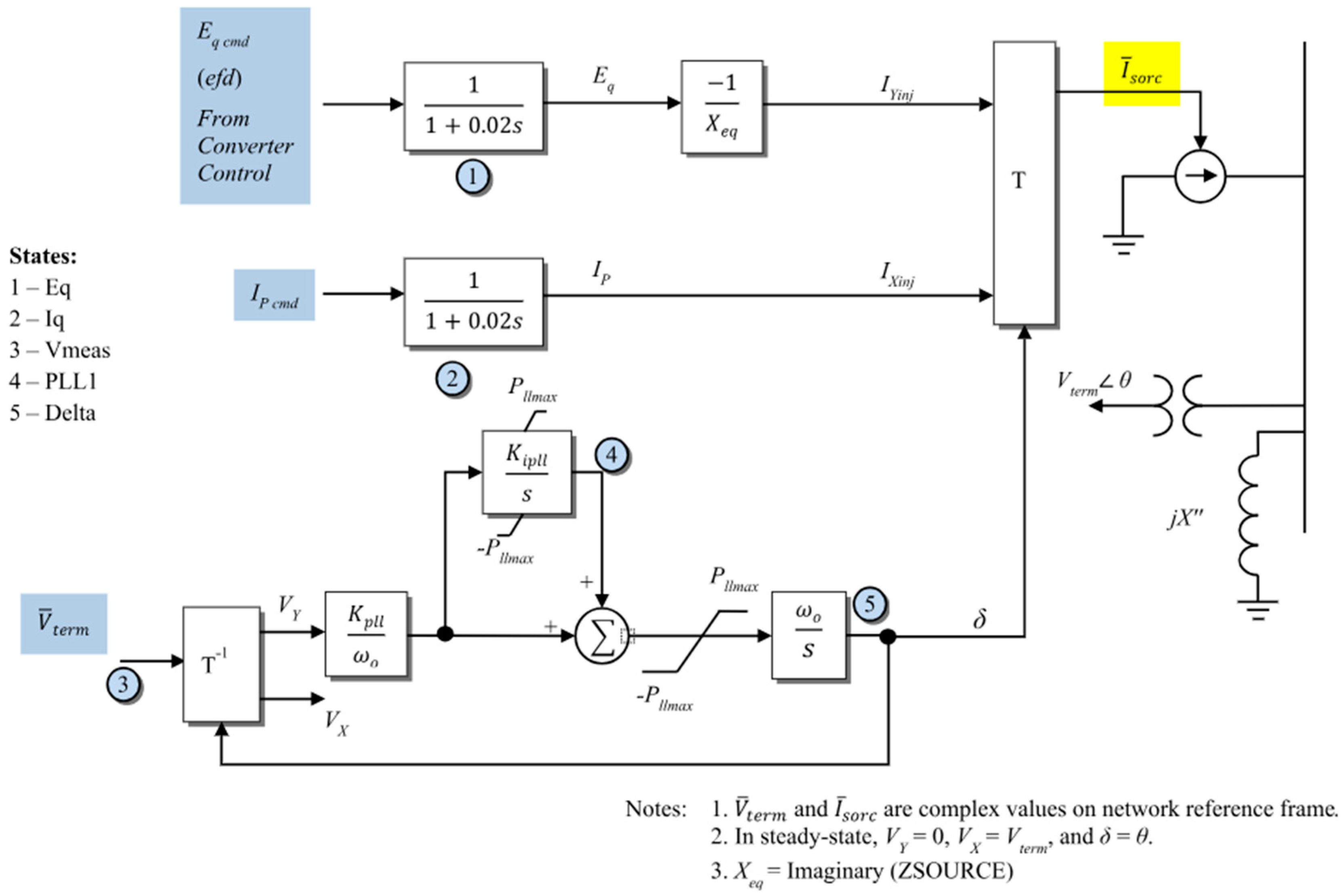
Figure 2.
Share of DFIG Penetration with respect to the active power dispatch and system inertia.
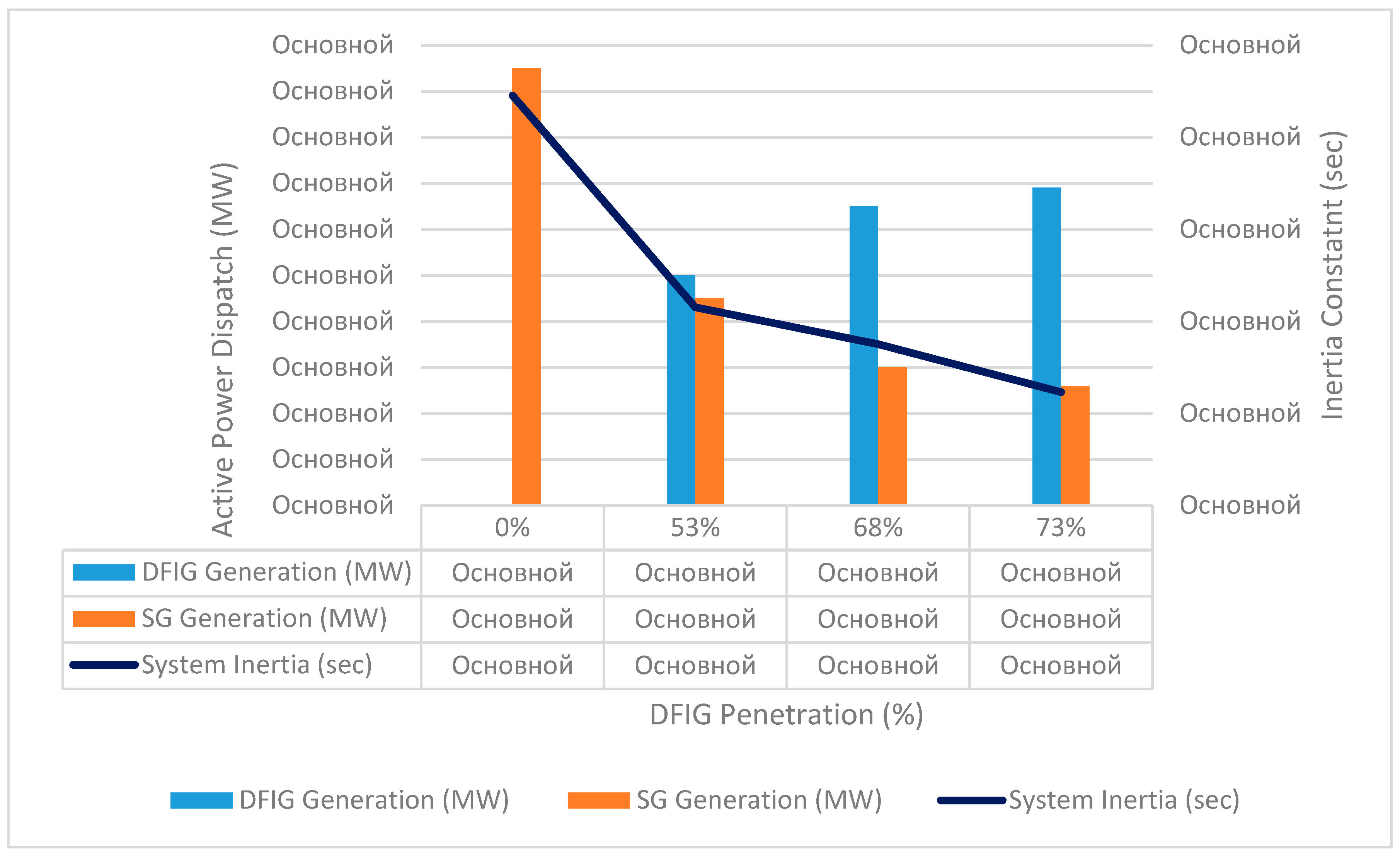
Figure 3.
The generator circuit connected to the SMIB via a transformer and two transmission lines.
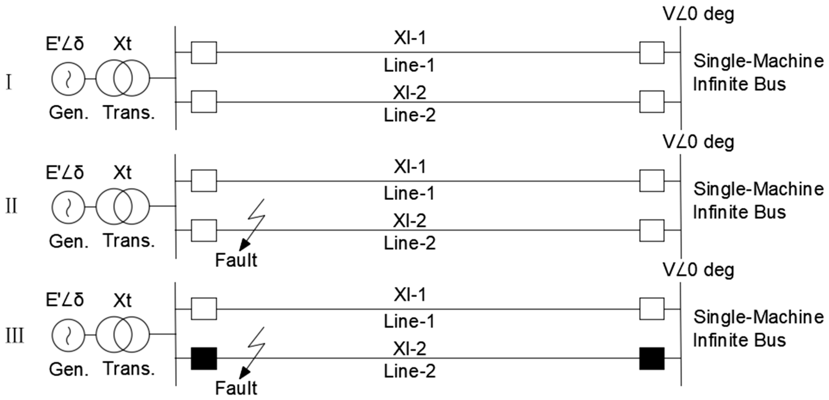
Figure 4.
Angular characteristics of the generator under three-phase short circuit and unsuccessful automatic reclose.
Figure 4.
Angular characteristics of the generator under three-phase short circuit and unsuccessful automatic reclose.
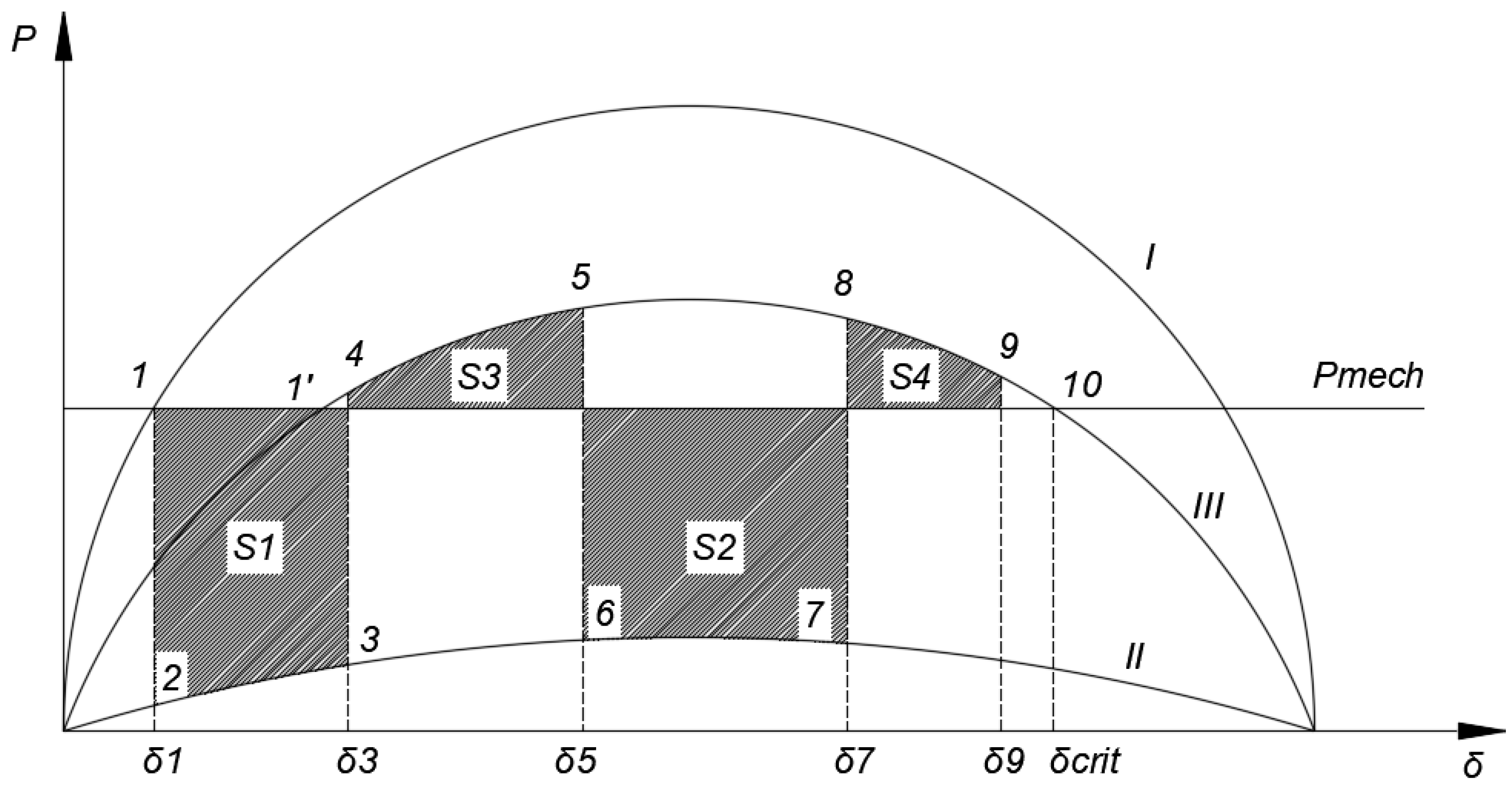
Figure 5.
Single-line diagram of the Mangystau energy system.
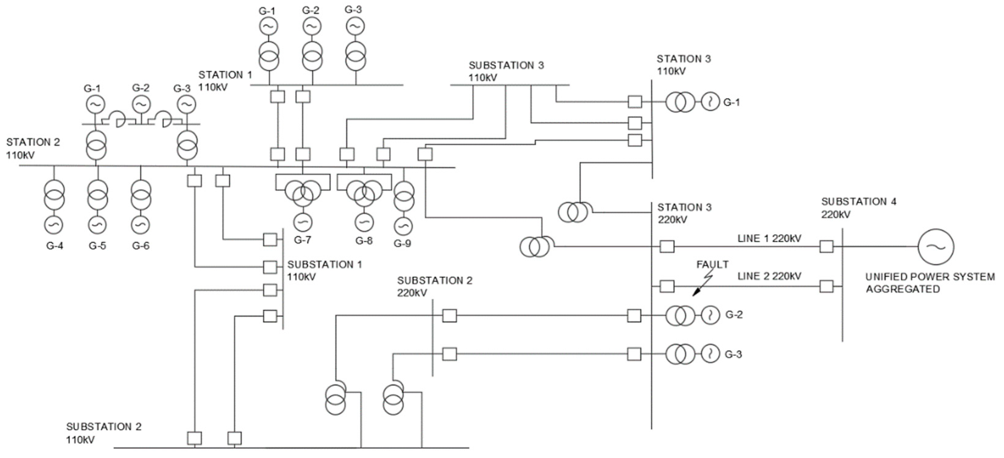
Figure 6.
Dynamic behavior of the system at 0 % generation from wind. (a) Relative angle of the rotors of synchronous generators relative to the base machine; (b) Voltage level at each node of the system; (c) Electrical frequency at each node of the system.
Figure 6.
Dynamic behavior of the system at 0 % generation from wind. (a) Relative angle of the rotors of synchronous generators relative to the base machine; (b) Voltage level at each node of the system; (c) Electrical frequency at each node of the system.
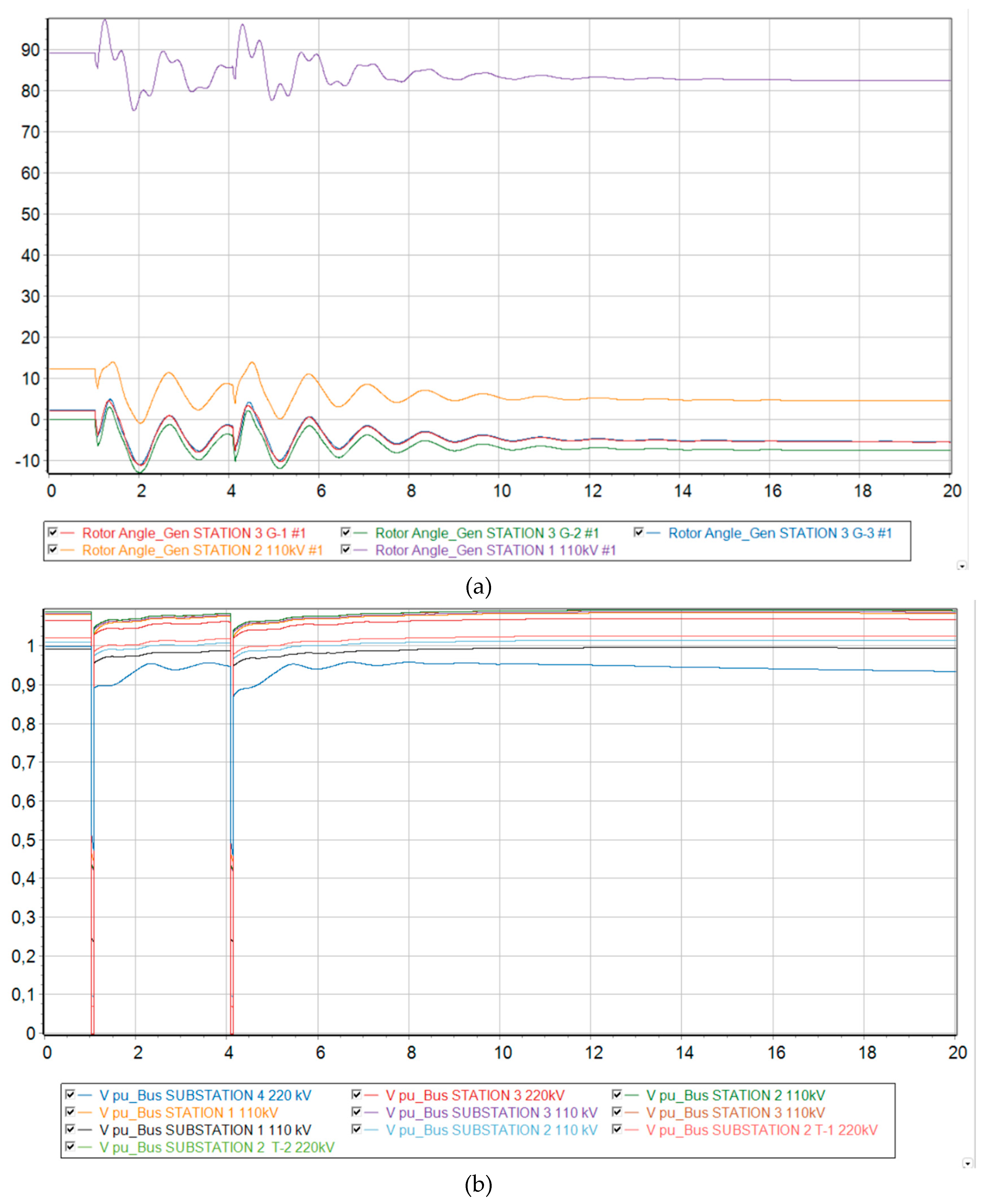
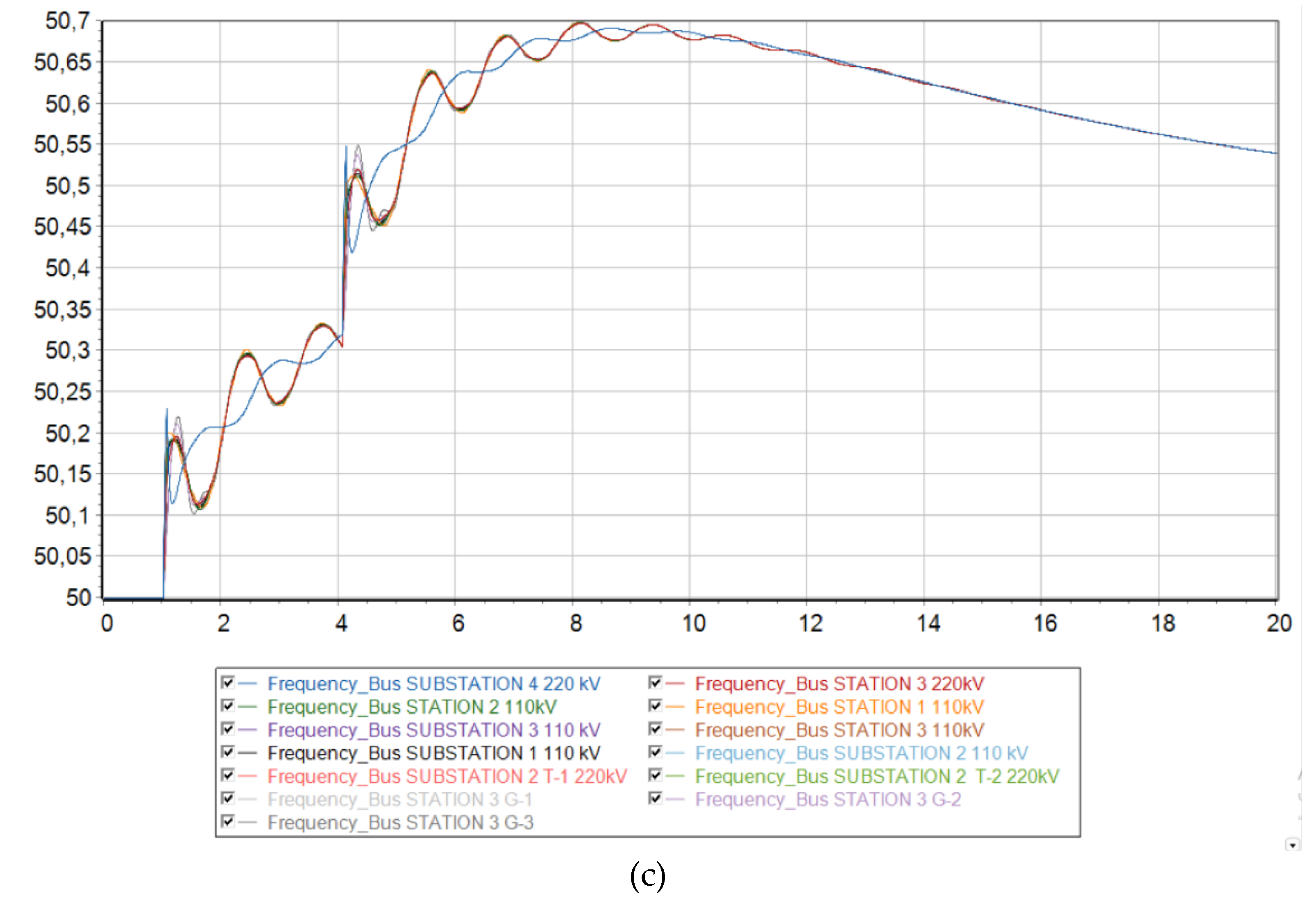
Figure 7.
Dynamic behavior of the system at 53 % generation from wind. (a) Relative angle of the rotors of synchronous generators relative to the base machine; (b) Voltage level at each node of the system; (c) Electrical frequency at each node of the system.
Figure 7.
Dynamic behavior of the system at 53 % generation from wind. (a) Relative angle of the rotors of synchronous generators relative to the base machine; (b) Voltage level at each node of the system; (c) Electrical frequency at each node of the system.
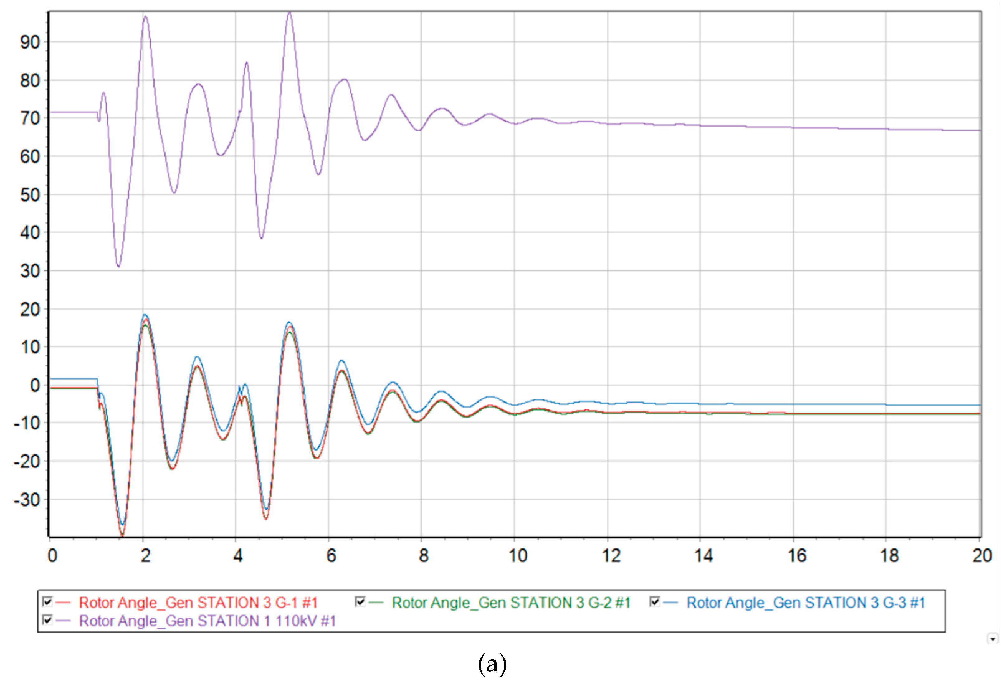
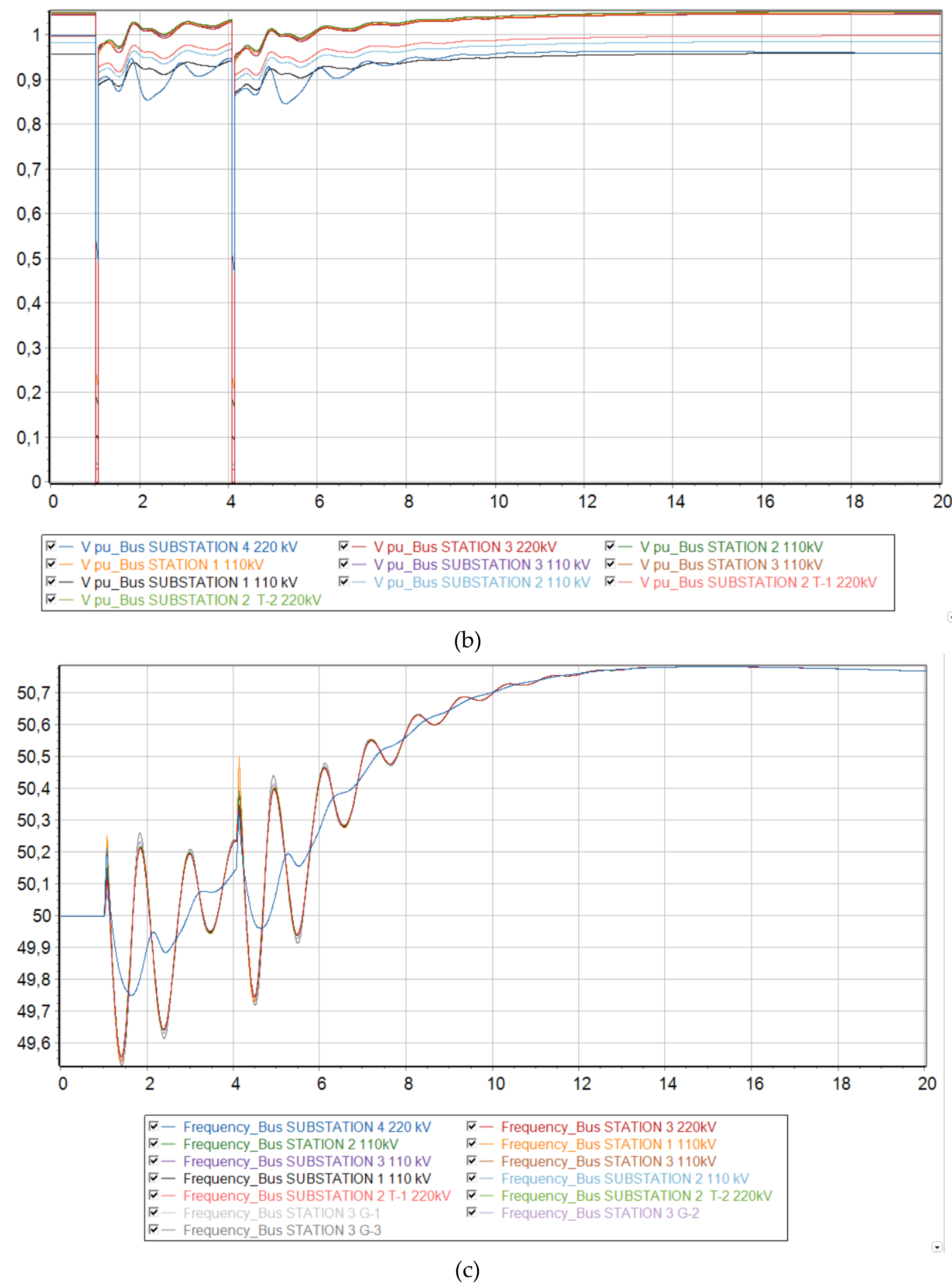
Figure 8.
Dynamic behavior of the system with 68 % generation from wind. (a) Relative angle of the rotors of synchronous generators relative to the base machine; (b) Voltage level at each node of the system; (c) Electrical frequency at each node of the system.
Figure 8.
Dynamic behavior of the system with 68 % generation from wind. (a) Relative angle of the rotors of synchronous generators relative to the base machine; (b) Voltage level at each node of the system; (c) Electrical frequency at each node of the system.
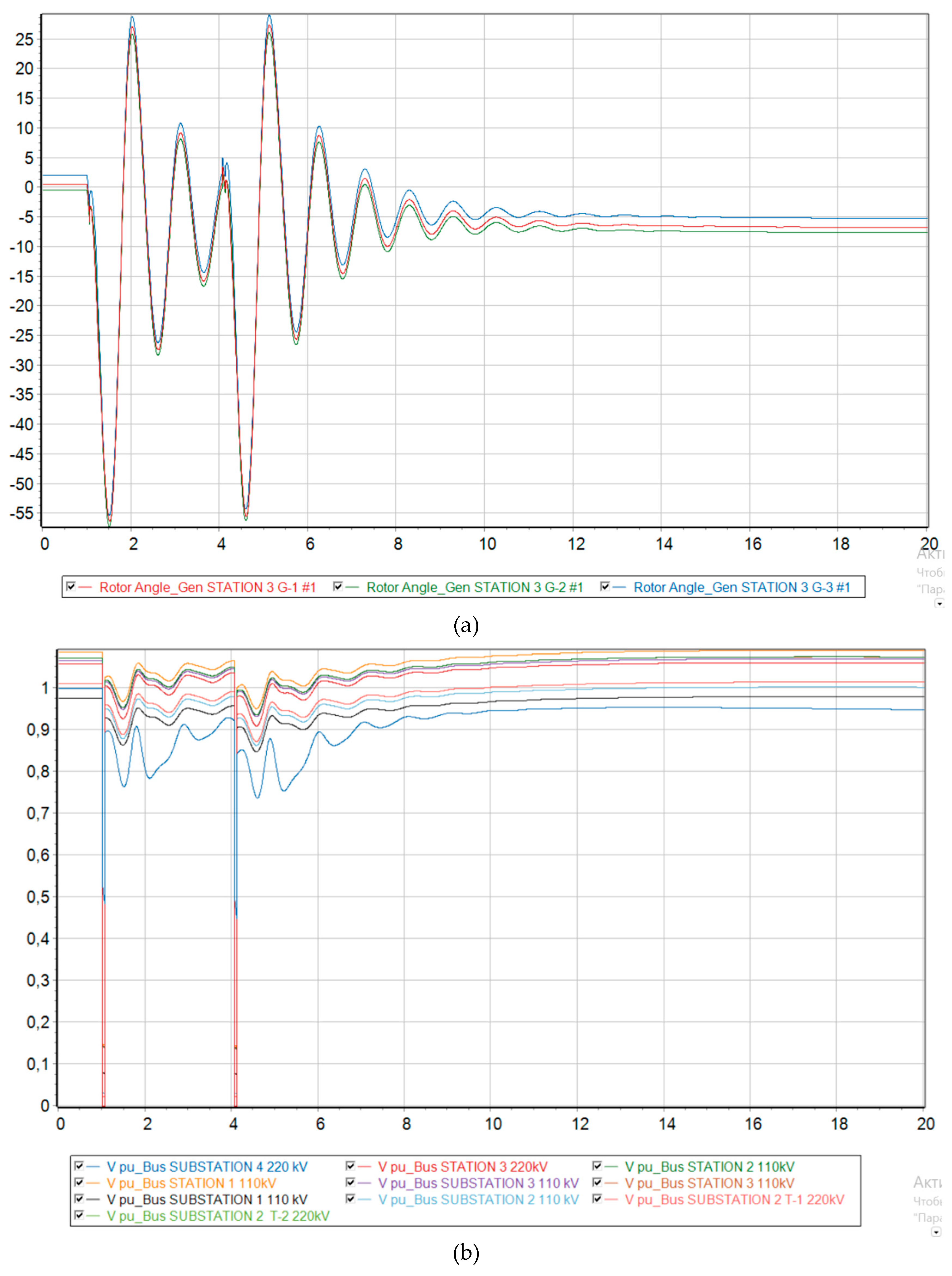
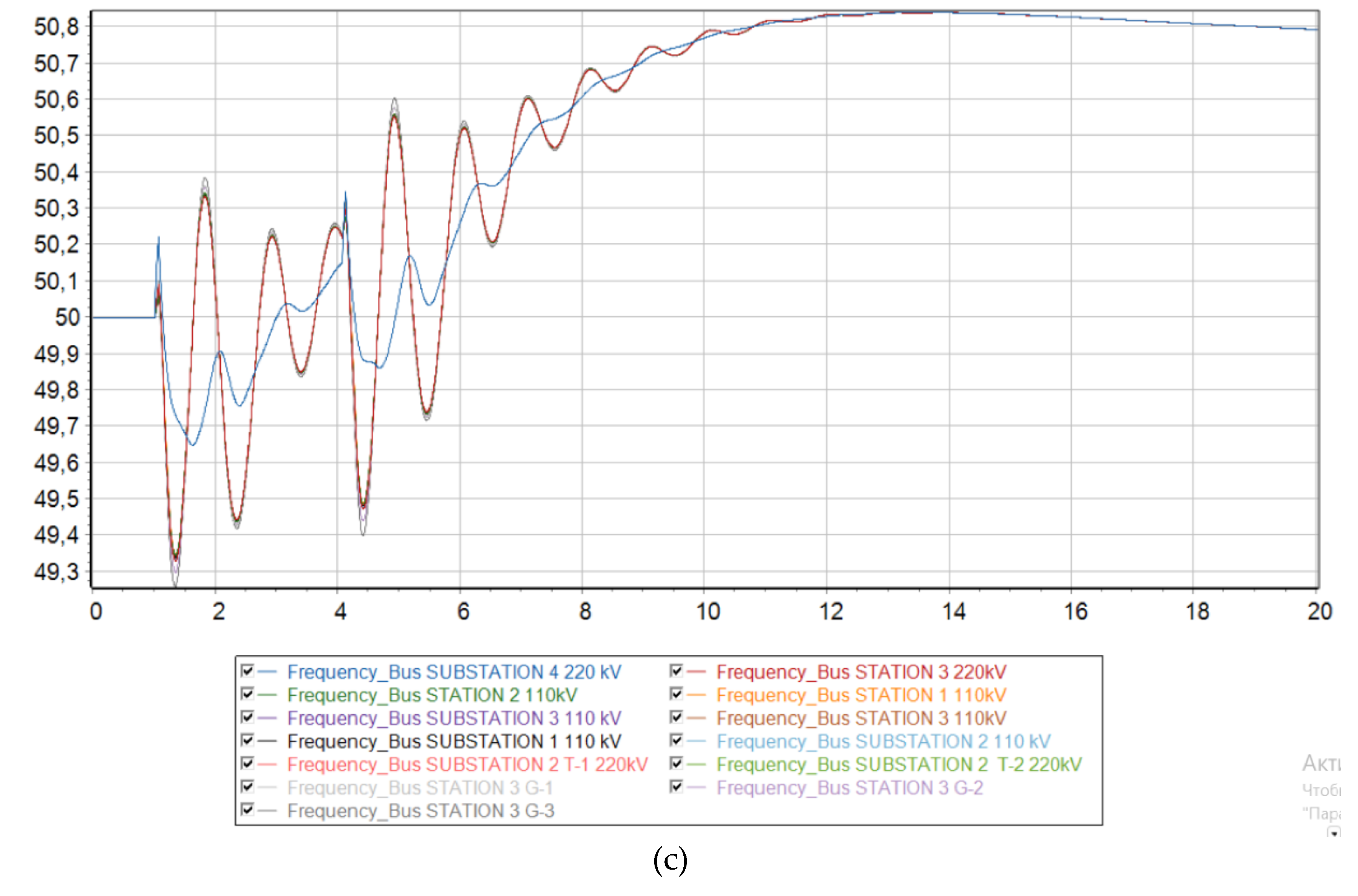
Figure 9.
Dynamic behavior of the system with 73 % generation from wind and the emergence of an asynchronous mode. (a) Relative angle of the rotors of synchronous generators relative to the base machine; (b) Voltage level at each node of the system; (c) Electrical frequency at each node of the system.
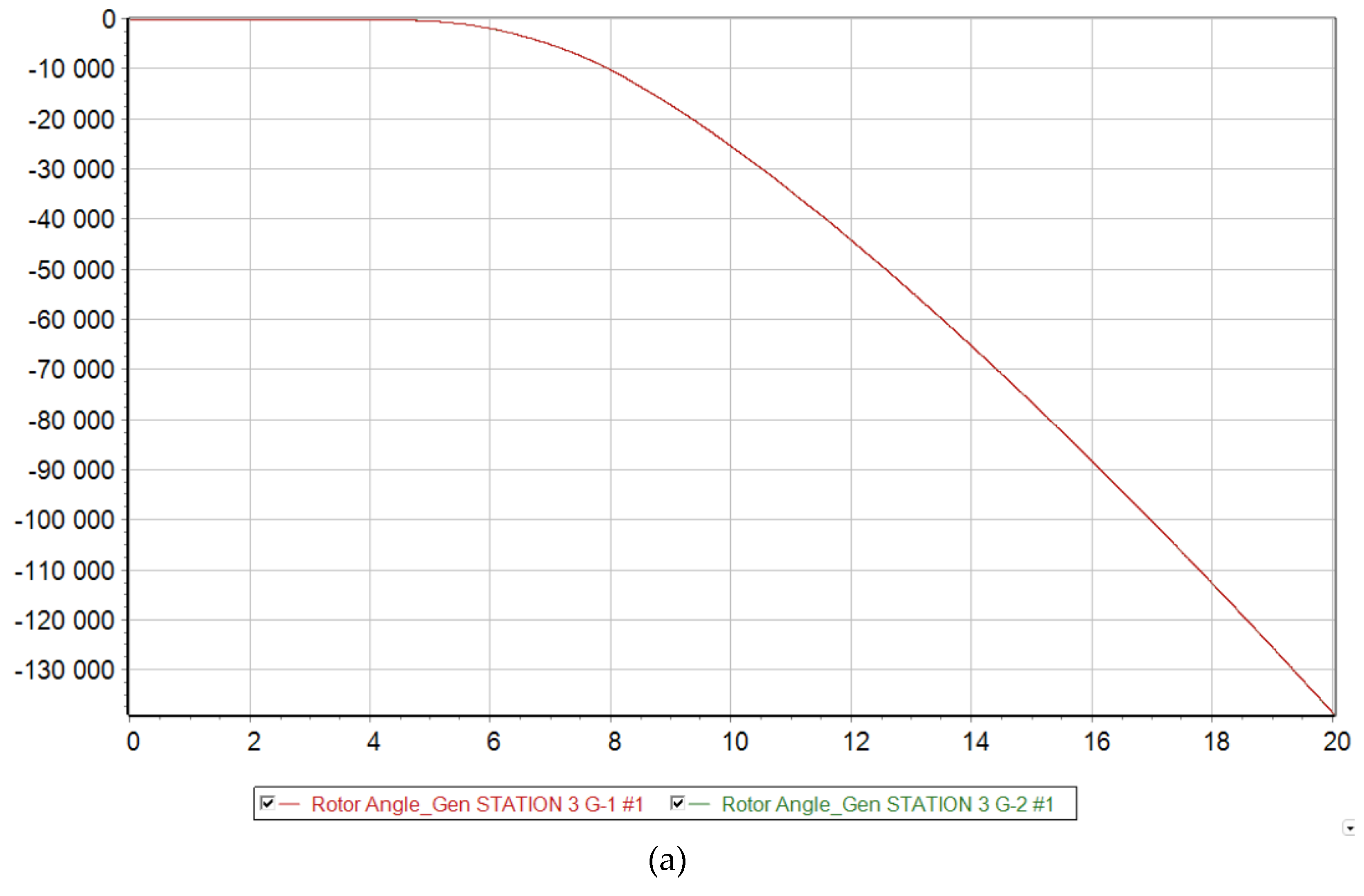
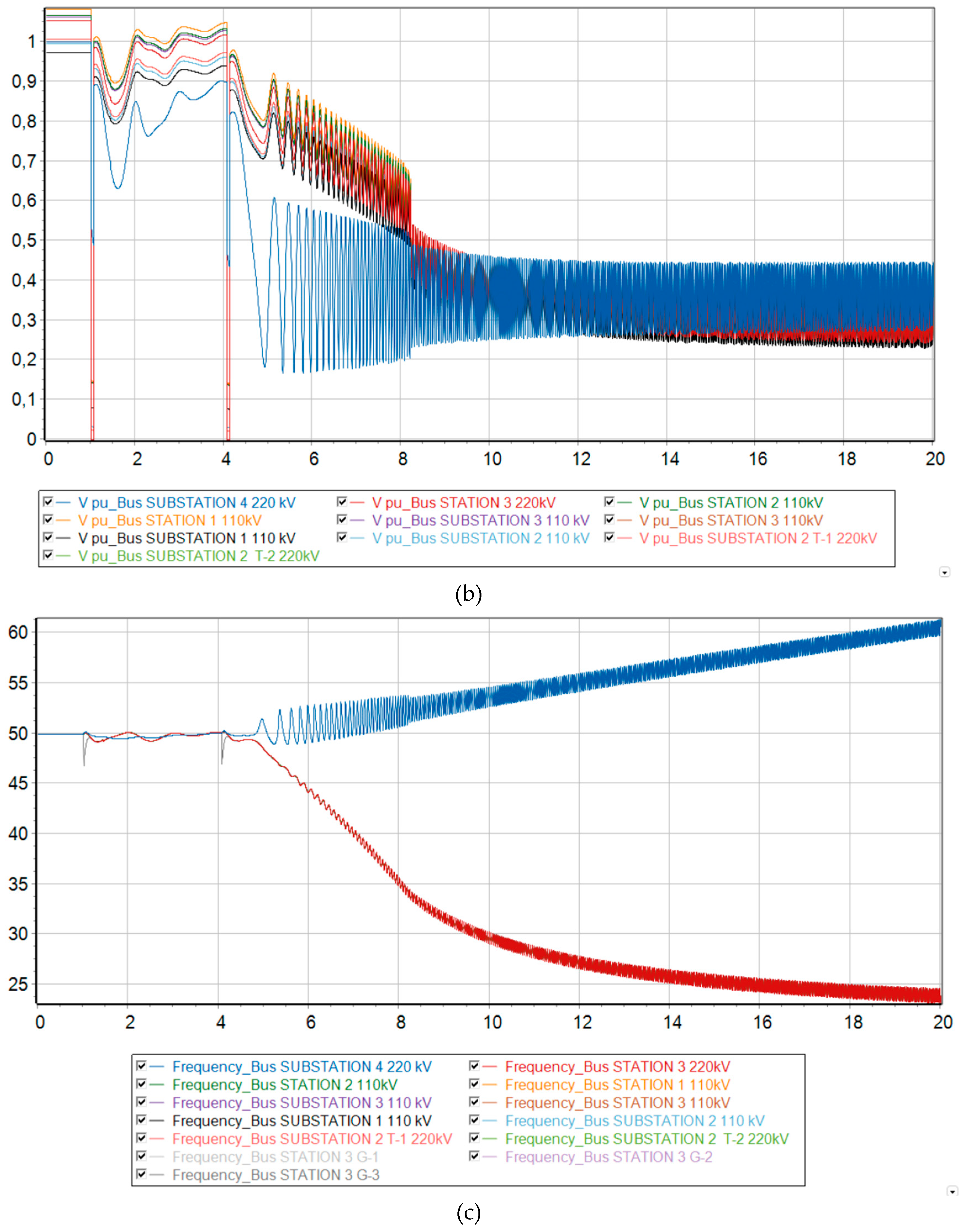
Figure 10.
Transient Stability Index of each synchronous generator with increasing DFIG penetration.
Figure 10.
Transient Stability Index of each synchronous generator with increasing DFIG penetration.
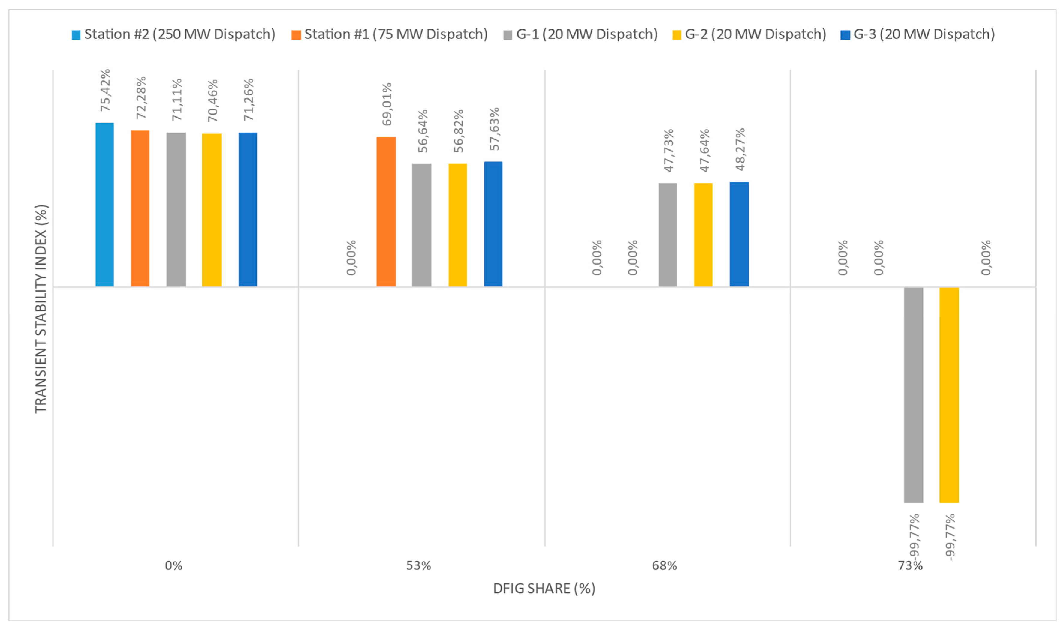
Figure 11.
Relative rotor angle of synchronous generators G-1 and G-2 at MNPP HPS at 73 % generation from DFIG. (a) No action taken; (b) with increasing AR time delay; (c) with a disconnection of 20 MW at the Uzen substation from SLSA.
Figure 11.
Relative rotor angle of synchronous generators G-1 and G-2 at MNPP HPS at 73 % generation from DFIG. (a) No action taken; (b) with increasing AR time delay; (c) with a disconnection of 20 MW at the Uzen substation from SLSA.
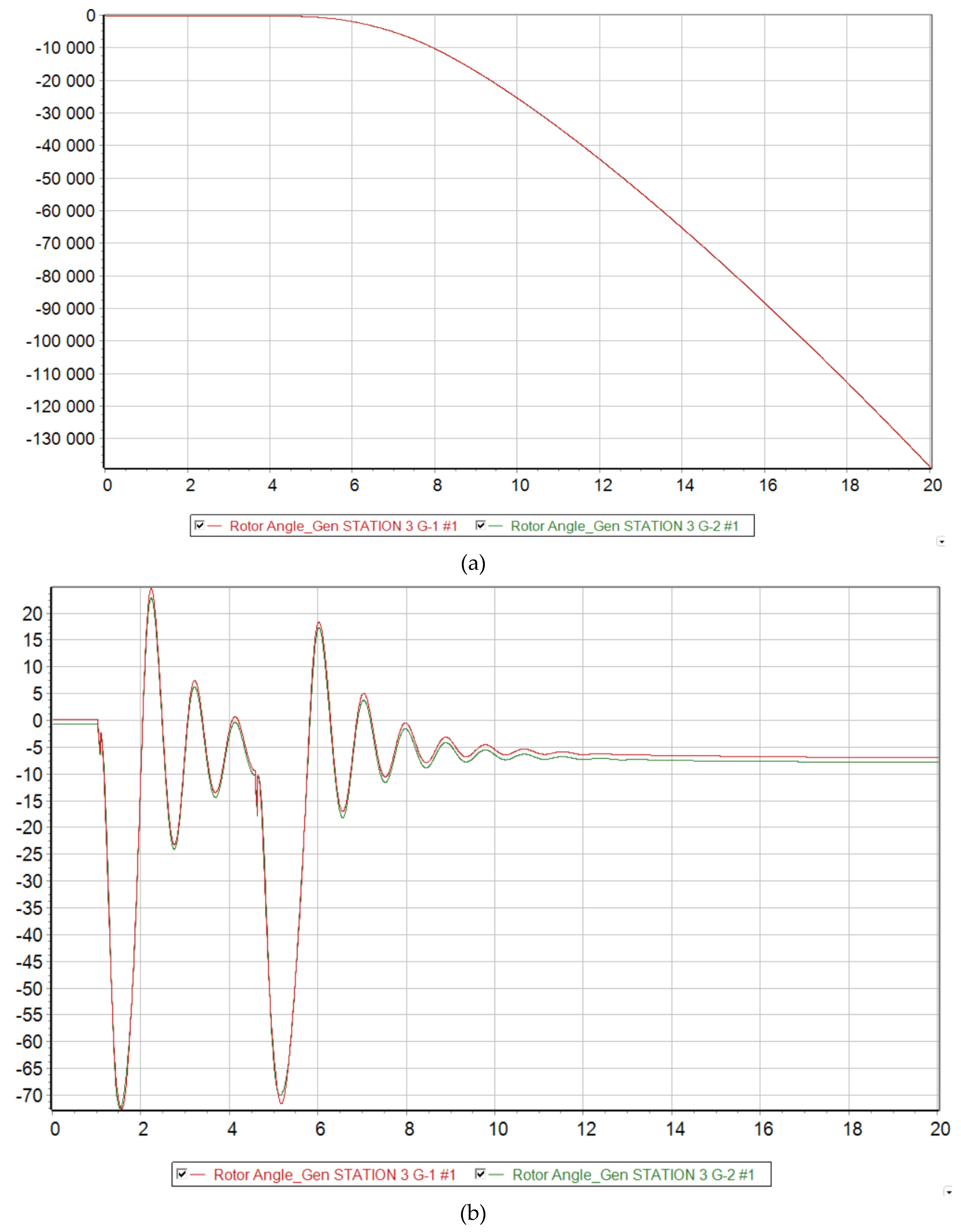
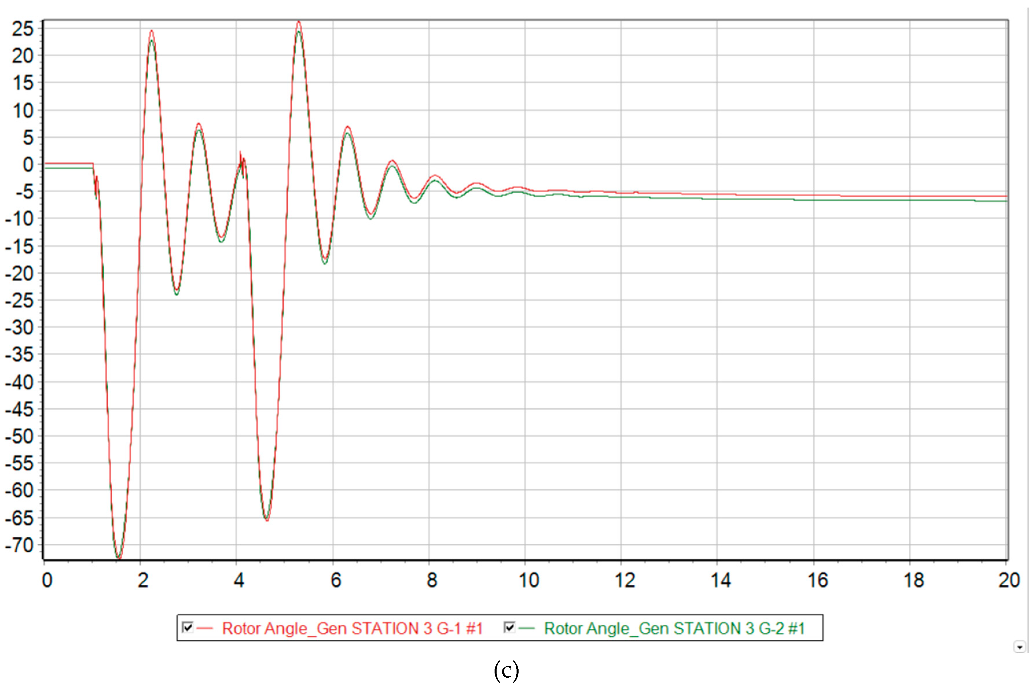
Figure 12.
Voltage levels at each node of the Mangistau system at 73 % generation from DFIG. (a) No action taken; (b) with increasing AR time delay; (c) with a disconnection of 20 MW at the Uzen substation from SLSA.
Figure 12.
Voltage levels at each node of the Mangistau system at 73 % generation from DFIG. (a) No action taken; (b) with increasing AR time delay; (c) with a disconnection of 20 MW at the Uzen substation from SLSA.
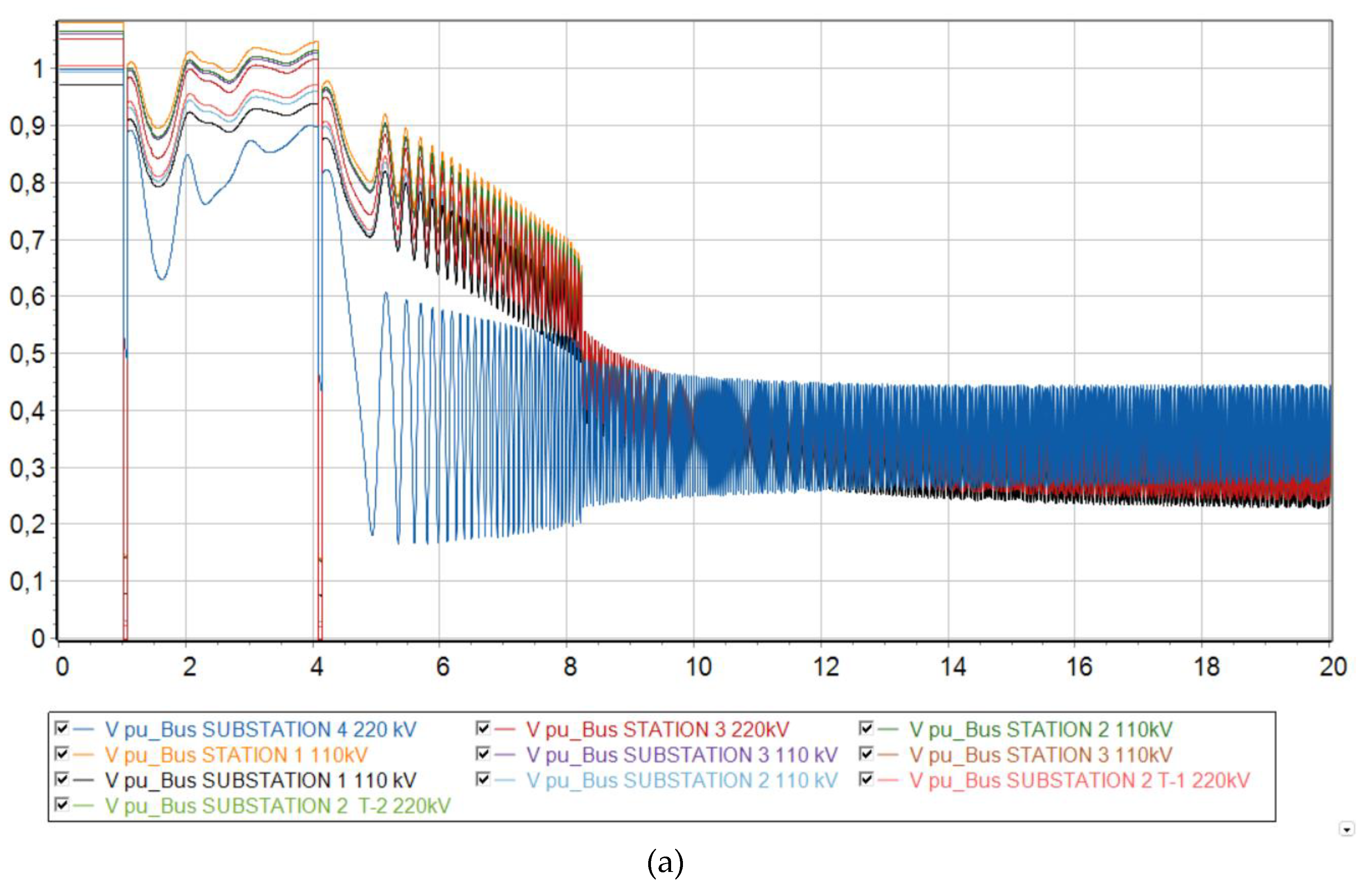
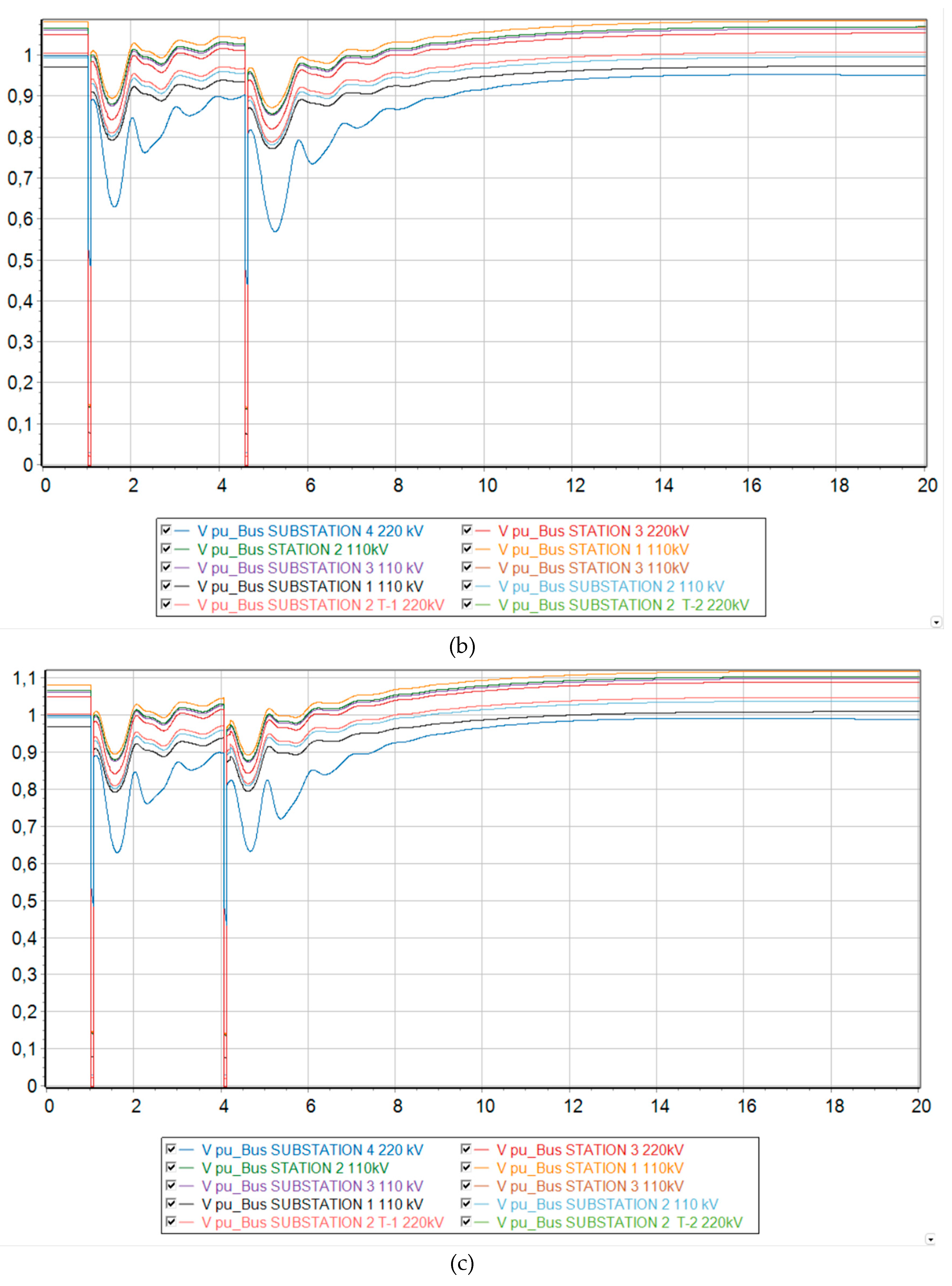
Figure 13.
TSI of G-1 and G-2 with 73% DFIG Penetration with respect to auto-reclose time.
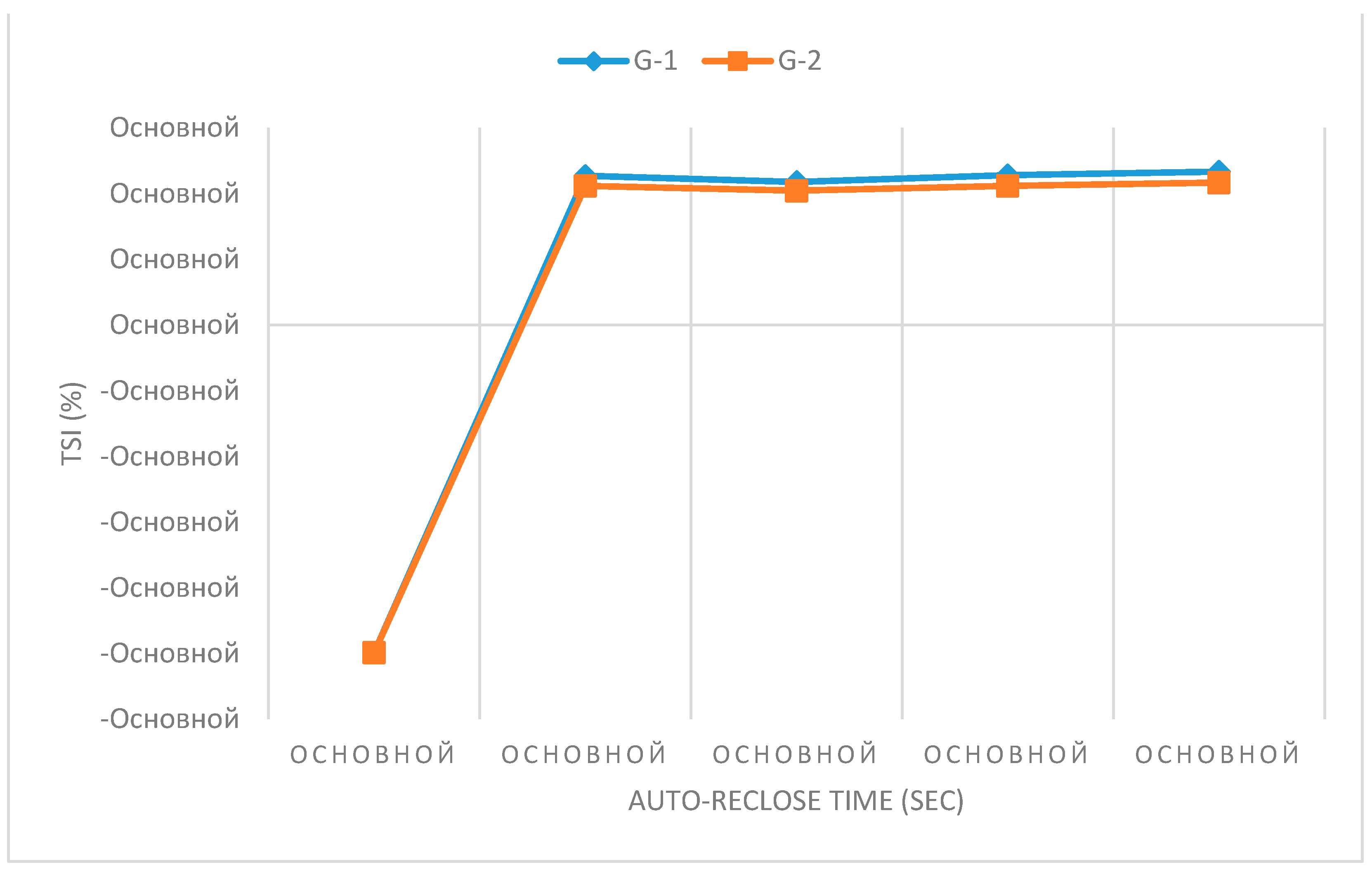
Figure 14.
TSI of G-1 and G-2 with 73 % DFIG Penetration with respect to the value of load-shedding.
Figure 14.
TSI of G-1 and G-2 with 73 % DFIG Penetration with respect to the value of load-shedding.
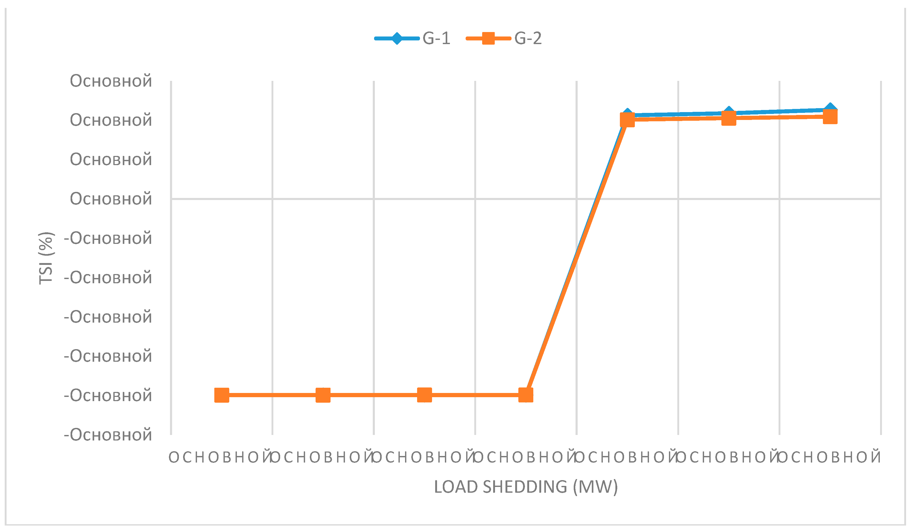

Table 1.
Composition of turbogenerators at power plants.
| Station name | Generator | Nominal Capacity (MW) |
| Station1 75 MW |
G-1 | 32 |
| G-2 | 32 | |
| G-3 | 32 | |
| Station 2 630 MW |
G-1 | 60 |
| G-2 | 60 | |
| G-3 | 60 | |
| G-4 | 100 | |
| G-5 | 60 | |
| G-6 | 60 | |
| G-7 | 63 | |
| G-8 | 63 | |
| G-9 | 100 | |
| Station 3 625 MW |
G-1 | 200 |
| G-2 | 210 | |
| G-3 | 220 |
Table 2.
Results of calculations of equivalent reactance of generators and inertias.
| Generator/Station | Transition resistance in rel. units (pu) | Synchronous resistance rel. units (pu) | Equivalent inertial constants (s) at Sb = 100 MVA |
| Station 1 | j0.3267 | j2.307 | 1.998 |
| Station 2 | j0.0544 | j0.27 | 11.5 |
| G-1 Station 3 | j0.136 | j0.807 | 3.083 |
| G-2 Station 3 | j0.141 | j0.829 | 3.081 |
| G-3 Station 3 | j0.116 | j0.897 | 2.604 |
| Unified Power System | j0.13 | j0.913 | 25 |
Table 3.
Transmission line impedances per unit.
| “From” Bus Name | “To” Bus Name | Circuit | Nominal Operating Voltage (kV) | Impedance in per unit (Sbase=100 MVA) |
| Station 1110 kV | Station 2110 kV | 1 | 110 | 0.023+j0.0415 |
| Station 1110 kV | Station 2110 kV | 2 | 110 | 0.023+j0.0415 |
| Station 2110 kV | Substation 3 | 1 | 110 | 0.007+j0.026 |
| Station 2110 kV | Substation 3 | 2 | 110 | 0.007+j0.026 |
| Substation 3 | Station 3110 kV | 1 | 110 | 0.007+j0.027 |
| Substation 3 | Station 3110 kV | 2 | 110 | 0.007+j0.027 |
| Station 2110 kV | Station 3110 kV | 1 | 110 | j0.0005 |
| Station 2110 kV | Substation 1 | 1 | 110 | 0.089+j0.222 |
| Station 2110 kV | Substation 1 | 2 | 110 | 0.089+j0.222 |
| Substation 1 | Substation 2 | 1 | 110 | 0.102+j0.192 |
| Substation 1 | Substation 2 | 2 | 110 | 0.102+j0.192 |
| Station 3220 kV | Substation 2 | 1 | 220 | 0.033+j0.106 |
| Station 3220 kV | Substation 2 | 2 | 220 | 0.033+j0.106 |
| Station 3220 kV | Substation 4 | 1 | 220 | 0.073+j0.322 |
| Station 3220 kV | Substation 4 | 2 | 220 | 0.073+j0.322 |
Table 4.
Transformers reactance in per unit.
| “From” Bus Name | “To” Bus Name | Operating Name of Autotransformer (AT) | Reactance in per unit |
| Station 3110 kV | Station 3220 kV | AT-1 | j0.0489 |
| Station 2110 kV | Station 3220 kV | AT-2 | j0.049 |
| Substation 2220 kV | Substation 2110 kV | AT-1 | j0.0428 |
| Substation 2220 kV | Substation 2110 kV | AT-2 | j0.0428 |
| G-1 | Station 3110 kV | AT-1 | j0.0419 |
| G-2 | Station 3220 kV | AT-2 | j0.0488 |
| G-3 | Station 3220 kV | AT-3 | j0.04797 |
Table 5.
Load schedule in the power system.
| Bus name | Active load (MW) | Reactive load (MVar) |
| Station 1110 kV | 20 | 10 |
| Station 2110 kV | 100 | 48 |
| Substation 3110 kV | 100 | 48 |
| Station 3220 kV | 35 | 40 |
| Substation 1110 kV | 100 | 62 |
| Substation 2110 kV | 80 | 39 |
| Substation 4220 kV | 31 | 19 |
| Total Load | 466 | 266 |
Table 6.
Generation schedule and terminal voltage level of the generators.
| Generator | Active power dispatch (MW) | Voltage (per unit) |
| Station 1 | 75 | 1.05 |
| Station 2 | 250 | 1.09 |
| G-1 Station 3 | 20 | 1.09 |
| G-2 Station 3 | 20 | 1.09 |
| G-3 Station 3 | 20 | 1.09 |
| Unified Power System | 90 | 1 |
| Total Generation | 475 |
Disclaimer/Publisher’s Note: The statements, opinions and data contained in all publications are solely those of the individual author(s) and contributor(s) and not of MDPI and/or the editor(s). MDPI and/or the editor(s) disclaim responsibility for any injury to people or property resulting from any ideas, methods, instructions or products referred to in the content. |
© 2024 by the authors. Licensee MDPI, Basel, Switzerland. This article is an open access article distributed under the terms and conditions of the Creative Commons Attribution (CC BY) license (http://creativecommons.org/licenses/by/4.0/).
Copyright: This open access article is published under a Creative Commons CC BY 4.0 license, which permit the free download, distribution, and reuse, provided that the author and preprint are cited in any reuse.


