1. Introduction
Since neural networks are widely used in computer science [
1], remote sensing [
2], autonomous control systems [
3], and other fields, their dynamic behaviors have been extensively studied over the past several decades. It is worth noting that neural networks (NNs) only consider the dynamic level of neural activity. However, it is essential to recognize that synaptic weights between neurons change over time [
4]. Consequently,
et al. [
5] developed competitive neural networks (CNNs) with different time scales in 1996, which can be viewed as an extension of Hopfield neural networks and cellular networks [
6,
7]. CNNs are defined using two types of state variables: short-term memory (STM) describes the rapid neural activity, while long-term memory (LTM) depicts the slow, unsupervised synaptic modifications. On the other hand, coupled competitive neural networks(CCNNs) consist of several interconnected subsystems, and due to their complex dynamic behavior, they have garnered significant attention [
8,
9].
The activation functions of NNs are widely recognized for describing the connection between the input and output of a single neuron. They are commonly considered to be continuous. When the activation function is believed to be at the high gain limit, however, the activation function approaches discontinuity. As a result, an increasing number of scholars have been conducting considerable research on NNs with discontinuous activation functions [
10,
11,
12,
13]. On the other hand, the dynamic behaviors of NNs are frequently impacted by external disturbances, such as changs in network structure, hardware facilities and environmental noise. As far as we are aware, there are few studies take both discontinuous activation functions and external disturbances into account when discussing CCNNs. Therefore, it is both intriguing and challenging to research discontinuous activation functions and external disturbances in CCNNs.
Synchronization means that two or more dynamical systems adjust themselves to exhibit a common dynamical behavior. The synchronization problem of NNs has garnered significant attention recently due to its wide applicability in communication systems, biological sciences, mechanical engineering and other domains [
14,
15,
16,
17]. However, the synchronization of the aforementioned NNs only considers the cooperative relationships between network nodes. In many practical systems, relationships of competition and cooperation coexist. Therefore, the synchronization issue of NNs with both competitive and cooperative connections between nodes, known as bipartite synchronization, is of crucial importance and has been researched in [
18,
19]. On the other hand, due to inherent network constraints, complete synchronization may not be achievable, and instead, quasi-synchronization is observed. Quasi-synchronization implies that the synchronization error no longer approaches zero but rather converges to a bounded set. To our knowledge, few papers have addressed the quasi-bipartite synchronization problem of CCNNs.
In addition to asymptotic synchronization or exponential synchronization, finite-time (FET) synchronization has gained widespread attention as a more practical form of network synchronization in recent years. In FET synchronization, the synchronization time is bounded, but it is dependent on the initial state of the node. To eliminate this dependence on the initial state, fixed-time synchronization is proposed based on the fixed-time (FXT) stability [
20], and its synchronization time only depends on the system or control parameters. Compared with the rich results of NNs [
21,
22], it is extremely scarce at present to explore the FXT synchronization of CCNNs. In [
23], authors studied the FET bipartite synchronization of delayed CCNNs under quantized control. Whereas, to our knowledge, there are limited reports on FXT quasi-bipartite synchronization of CCNNs, and further research is needed.
Over the past few decades, the control problem of networks has been one of the most widely studied topics, and many useful control methods have been developed, such as adaptive control, sliding mode control, impulse control, and intermittent control, among others. Intermittent control involves alternating periods of applying control input and periods of no control input, making it a more economical choice compared to continuous control schemes. Hence, the intermittent control strategy has received extensive attention [
24,
25,
26,
27]. In [
28], the FXT synchronization problem of time-delay complex networks under intermittent pinning control is studied. The author in [
29] solved the FXT and predefined-time cluster lag synchronization of stochastic multi-weighted complex networks via intermittent quantized control. To our knowledge, there is currently no existing literature that addresses the challenging problem of FXT quasi-bipartite synchronization of CCNNs under intermittent control.
Motivated by the analysis provided above, the primary objective of this paper is to investigate FXT quasi-bipartite synchronization in coupled competitive neural networks. Firstly, the model under consideration incorporates time-varying delays, discontinuous activation functions, and external disturbances simultaneously, rendering it more comprehensive. Secondly, we introduce an innovative FXT aperiodic intermittent control scheme, making the pioneering endeavor to explore quasi-bipartite synchronization in CCNNs. Furthermore, some robust criterion are established for FXT quasi-bipartite synchronization based on the theory of practical FXT stability. Finally, we provide estimations for error bounds and settling times.
Below are shown the remaining contents.
Section 2 gives some necessary preliminary knowledge and model description.
Section 3 introduces the main theoretical conclusions.
Section 4 provides numerical examples to validate the theoretical conclusions.
Section 5 finishes our study and discusses future research.
Notations: R represents the set of real numbers. The n-dimensional Euclidean space is represented by the . is the set of real matrices. . is identity matrix. denotes zero matrix. . For a symmetric matrix B, represents the maximum eigenvalue of matrix B. represents the diagonal matrix. denotes that all elements of a column vector are 1. For any , , represents the function. . The 2-norm of the vector p is denoted by . For vector , all of the components of are positive (negative, non-negative, non-positive). For vectors and , implies . Notation ⊗ denotes Kronecker product. , denotes the set of continuous function from to .
2. Model description and preliminaries
Consider the following competitive neural networks with time-varying delay:
where
is the state variable.
represents synaptic efficiency.
represents the self-feedback coefficient. Connection weights and delay connection weights, respectively, are represented by
and
.
is the output of neuron which is discontinuous.
is the weight of an external stimulus.
and
are given constants.
is the intensity of the external stimulus.
is the time scale of
. Where
is a known constant,
is the time-varying delay that satisfies
.
Let
,
and
. Without losing generality, suppose
, then network (1) can be written as
where
,
,
,
,
,
,
,
. The initial value of system (2) is given by and .
A class of CCNNs with external disturbances are modeled as follows:
where
and
are the state variables of
and
, respectively;
indicates the external disturbance vector.
and
are the adjacency matrix associated with the signed graph
and
of the CCNNs, satisfying
for
; for
,
if there is a directed communication link from node
j to node
i, otherwise
.
and
are controllers to be designed. The initial conditions of network (3) meet:
and
.
Remark 1. When , then the connection between nodes i and j is cooperative, the coupling term is given as . When , the connection between nodes i and j is competitive, the coupling term is presented as .
For the convenience of discussion, define , , , , , , , and .
Therefore, the coupled competitive neural networks (3) become:
From (2), the tracking target can be described as follows:
where
is the state vector.
The necessary definitions, lemmas and assumptions are given below.
Definition 1 ([
33]).
Considering a system with discontinuous right-hand sides in the form of
where , is locally bounded and Lebesgue measurable. The function is said to be the solution in Filippov sense which defined in the interval , if is absolutely continuous and satisfies the below differential inclusion
where the set-valued map is defined as
where stands for the convex closure, is the Lebesgue measure of the set Ω, denotes the open ball centered at with radius δ.
Definition 2.
The network (4) is said to achieve FXT quasi-bipartite synchronization with network (5) if there is a constant , such that
where θ is a nonnegative constant.
Definition 3 ([
34]).
Aperiodically intermittent control is said to have an average control rate , if there is such that
where denotes the total control interval length on , is called the elasticity number.
Lemma 1 ([
30]).
If , and , then
Lemma 2 ([
35]).
For any , and positive-definite matrix , such that
Lemma 3 ([
36]).
Assume that there is a Lyapunov function that satisfies
in which are positive constants and , . It is said system practical fixed time stable if and , in which . And the setting time satisfies
where , and . γ and are defined in Definition 3. When , there is
where , , .
For each , the following assumptions are introduced:
Assumption 1 ([
32]).
is continuous except on a countable set of isolated points , where both the left limit and right limit exist. In addition, has at most finite discontinuous jump points in each bounded compact set.
Assumption 2 ([
32]).
There exist positive constants and such that
where , with .
Assumption 3 ([
23]).
The signed graphs are structurally balanced. In other words, the node sets of G can be divided into two unsigned subgraphs and , respectively. It satisfies and . In addition, the links inside each subgraph are nonnegative, while the links between two unsigned subgraphs are negative.
Assumption 4.
The activation functions satisfies
Assumption 5. There exists a positive constant such that .
Assumption 6. The external disturbance is bounded. That is, there is a positive constant such that .
Assumption 3 implies that there exists a diagonal matrix
, where
if node
, otherwise
. To achieve the FXT quasi-bipartite synchronization of CCNNs, the intermittent controller is designed as follows:
where
,
,
,
,
,
are positive constants.
Remark 2.
The intermittent control proposed in this study can be accomplished in a fixed time, unlike the previous intermittent control, which can only achieve asymptotic results. Moreover, the aperiodic intermittent controller proposed in this study is different from the controller in [26,27] as follows:
and
A linear term does not need to be set in the rest interval. This approach is proposed first to achieve FXT quasi-bipartite synchronization for coupled competitive neural networks. Furthermore, aperiodic intermittent control can be degenerated into periodic intermittent control and continuous control. It is particularly suitable for complex systems that require dynamic and flexible control.
Combined with controller (8), when
, the CCNNs (4) is rewritten as follows:
where
,
for
and
. Then, according to Assumption 3, the CCNNs (9) can be transformed into:
where
,
for
and
,
.
Similar analysis, for
, one has
By definition 1, there is
such that
Similarly, there exists at least one measurable function
such that
3. Main result
In this part, we will consider the case of and . The Fixed-time quasi-bipartite synchronization criterion is derived by designing intermittent controller.
Define the synchronization error
, then the error dynamical system is:
where
,
.
3.1. Fixed-time quasi-bipartite synchronization without disturbances
This section gives the results without external disturbances. Firstly, Theorem 1 gives a sufficient condition for the quasi-bipartite synchronization of networks (12) and (13) in fixed time.
Theorem 1.
Based on Assumptions 1-5 and the controller (8), if
where , , λ, , d are positive constants, stands for the average control rate, then the quasi-bipartite synchronization can be ensured between networks (12) and (13) in fixed time. The settling time satisfies
here , , represents the elasticity number, . The state trajectory of (14) converges to a compact set , , , , , .
Proof. Consider the following Lyapunov function
where
.
For
, calculate the derivative of
along the trajectory of the error system (14), one has
Based on Assumption 2, we get
where
,
.
By Assumption 5, there is
where
.
From (15) and (16), one has
According to Lemma 1, one has
and
From Lemma 2, it follows that
and
It follows from (17)-(20) that
where
.
Therefore,
for
,
,
, and
.
Then, for
, we have
where
.
Based on Lemma 3, the networks (12) and (13) achieve FXT quasi-bipartite synchronization and the settling time is estimated as T. Moreover, the system error will converge to within T, where , , .
The theorem is proven. □
Remark 3. A previous study [23] focused on studying FET bipartite synchronization in competitive neural networks, whereby the settling time was dependent on the initial state. In contrast, Theorem 1 provides a sufficient condition for achieving FXT quasi-bipartite synchronization in CCNNs where the settling time is no longer dependent on the initial state, but rather on the adjustable controller parameters and the average control rate. Furthermore, our study utilizes a more practical intermittent controller compared to the one used in [23].
3.2. Fixed-time quasi-bipartite synchronization with disturbances
This section considers external disturbances. Theorem 2 gives sufficient conditions for quasi-bipartite synchronization of systems (12) and (13) in fixed time.
Theorem 2.
Based on Assumptions 1-6 and the controller (8), if
where , , ψ, λ, are positive constants, stands for the average control rate, then the quasi-bipartite synchronization can be ensured between networks (12) and (13) in fixed time. The settling time satisfies
here , , represents the elasticity number, . The state trajectory of (14) converges to a compact set within , , , , , .
Proof. Construct the following Lyapunov function
where
.
For
, one obtains
Based on Assumption 2 and Assumption 5, it is clear that there are
where
,
,
.
Combining (21) and (22), one has
By Lemma 1, it is easy to get
Based on Lemma 2, we obtain
Submitting (24) and (25) into (23), we obtain
where
,
,
,
.
For
, we obtain
where
.
Based on Lemma 3, the FXT quasi-bipartite synchronization can be realized and the settling time is estimated as . Moreover, the system error will converge to within , where , , .
The theorem is proven. □
Remark 4. Unlike prior studies [31,36], our research takes into account the impact of discontinuous activation functions, external disturbances, and competitive relationships between nodes, which more closely mimics real-world networks. Specifically, due to the competitive nature among nodes and the presence of external disturbances, the synchronization method employed in [36] is not directly applicable to achieve FXT quasi-bipartite synchronization. Consequently, our main theorem extends the prior findings of FXT bipartite synchronization and is tailored to suit the aforementioned conditions.
Remark 5. Predefined time control has emerged as a promising method that allows synchronization time to be pre-set independently of system parameters. Due to its potential in various applications, predefined time synchronization has become a highly topical research area. However, there is still insufficient research into the predefined time bipartite synchronization of CCNNs, therefore further investigation is necessary.
4. Numerical examples
Two numerical examples are given in this part to demonstrate the validity of the derived theoretical conclusions.
Consider the following networks:
where
,
,
,
,
,
,
,
,
,
,
,
.
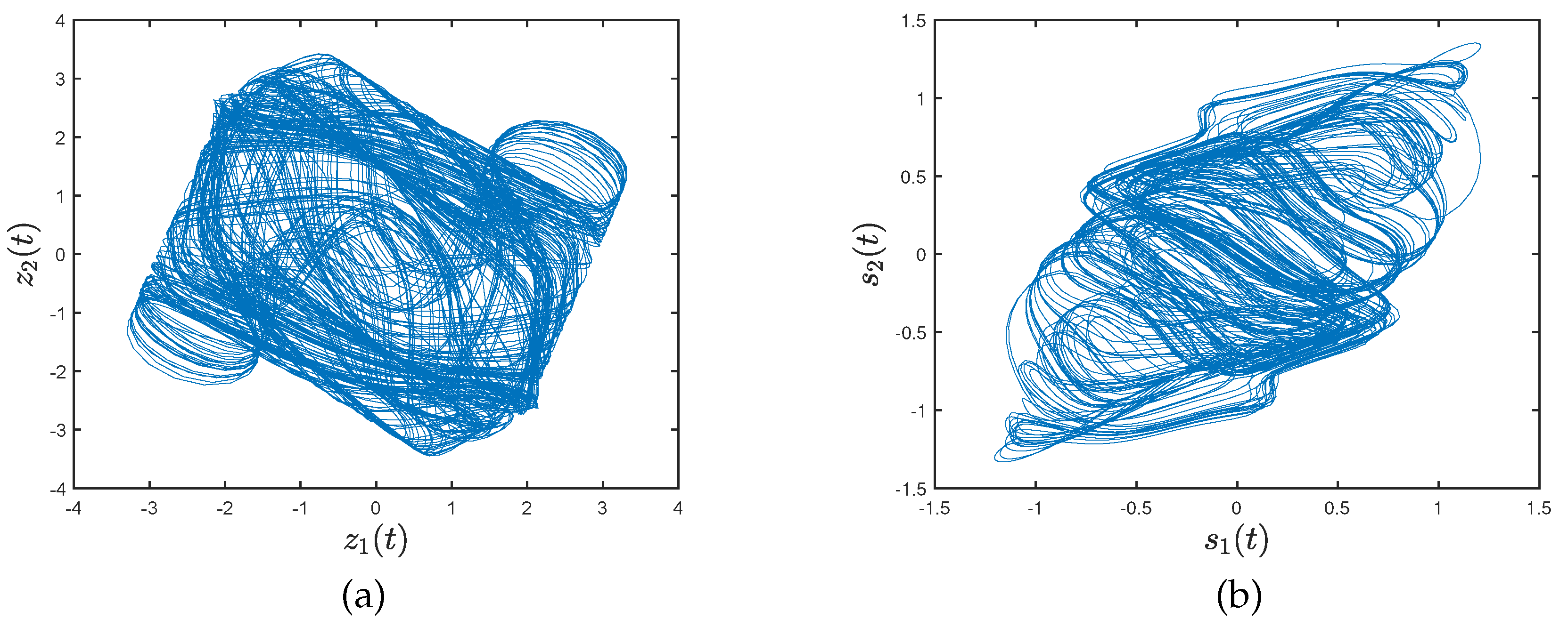
Figure 1 shows the chaotic trajectories of network (26) with initial values
,
.
4.1. Fixed-time quasi-bipartite synchronization without disturbances
Now, consider CCNNs with 7 nodes as follows:
where
,
,
. Set the initial values of network (27) to be
,
,
,
,
,
,
,
,
,
,
,
,
,
,
.
The topology of the networks (27) are presented in
Figure 2. Let
,
, and take
,
.
Figure 3 depicts the trajectories of networks (26) and (27) under controller (8).
The control intervals of the intermittent controller is designed as follows:
By simple calculation,
and
. Choose
,
,
,
,
,
,
,
and
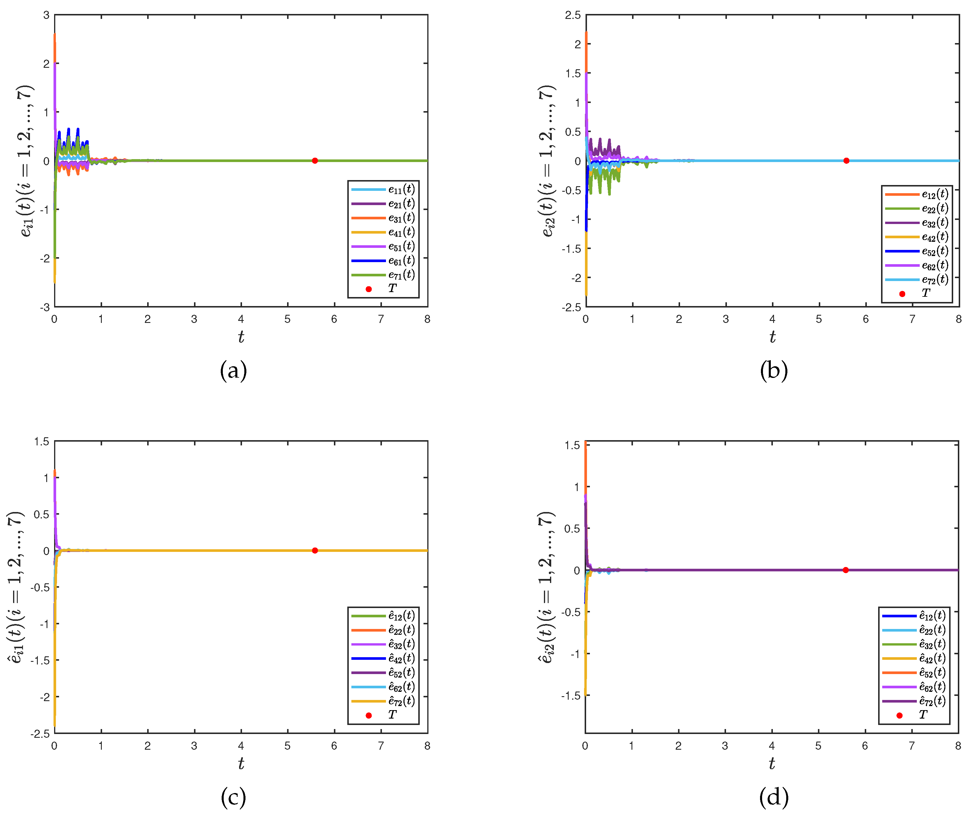
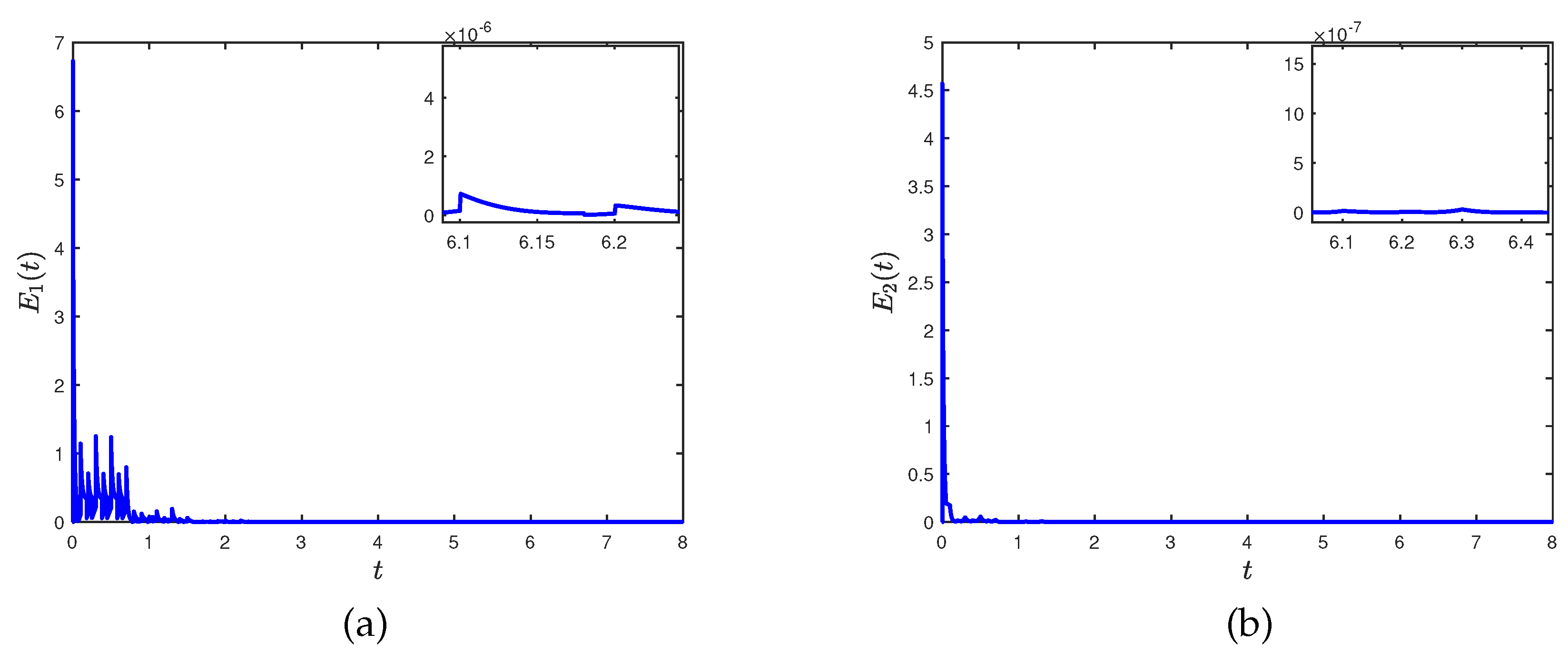
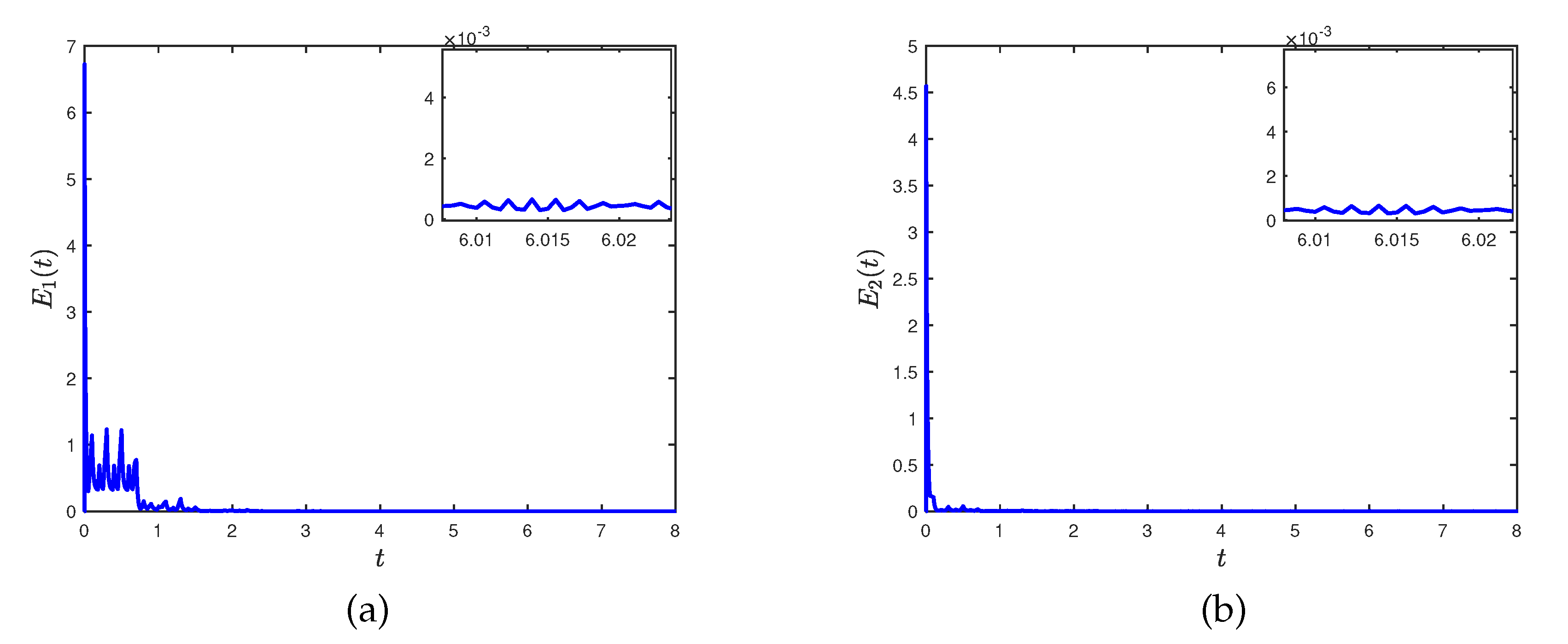
. By Theorem 1, the networks (26) and (27) are FXT quasi-bipartite synchronization and it is obtained that
and error bound is 2.96. The simulation results are presented in
Figure 4 and 5.
4.2. Fixed-time quasi-bipartite synchronization with disturbances
Consider the CCNNs with 7 nodes as follows:
the model parameters are selected in section 4.1, where
,
.
Figure 6 presents the trajectories of (26) and (28) with controller (8).
In the following, the FXT quasi-bipartite synchronization of the networks (26) and (28) will be verified. According to the parameters in section 4.1,
,
and
. Select
,
,
,
,
,
,
,
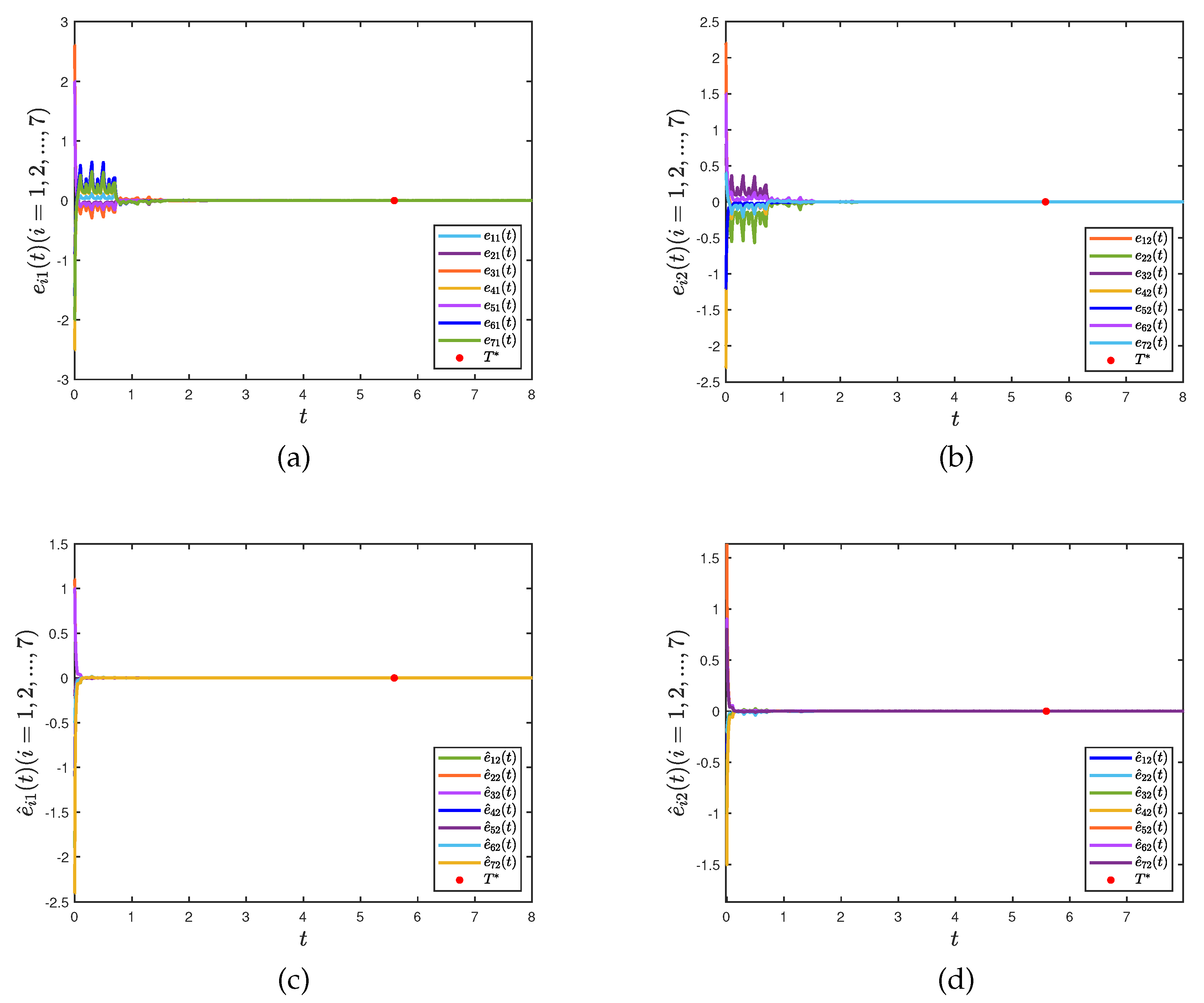
. Evidently, all conditions in Theorem 2 are satisfied and the networks (28) with controller (8) is synchronized with (26) within settling time
. Theoretical error bound is 2.97. The corresponding numerical results are illustrated in
Figure 7 and 8.
5. Conclusion
In this study, the problem of FXT quasi-bipartite synchronization for CCNNs is considered by intermittent control strategy. Compared with the existing FXT intermittent control strategy, the linear term on the rest interval is removed, which makes our control method simpler and more economical. In addition, the influence of discontinuous activation functions, external disturbances and competitive relationships between nodes are considered in synchronous analysis, which makes the obtained criteria more general. Note that we can implement control measures on all nodes to achieve FXT synchronization when network topology is known. In practical scenarios, it is often either infeasible or unnecessary to control every single node. Therefore, the intermittent pinning control will be considered in forthcoming research.
Author Contributions
Methodology, S.T. and J.L.; formal analysis, S.T.; resources, J.W.; writing—original draft preparation, S.T.; writing—review and editing, S.T. and J.L.; supervision, H.J. and J.L.; All authors have read and agreed to the published version of the manuscript.
Funding
This research received no external funding.
Institutional Review Board Statement
Not applicable.
Informed Consent Statement
Not applicable.
Data Availability Statement
Not applicable.
Acknowledgments
This work was supported by the Natural Science Foundation of Xinjiang Uygur Autonomous Region (Grants No. 2021D01C113, No. 2021D01D10), the National Natural Science Foundation of People’s Republic of China (Grants No. 62006196, No. 62163035), and Xinjiang Key Laboratory of Applied Mathematics (Grant No. XJDX1401).
Conflicts of Interest
The authors declare no conflicts of interest.
References
- Cai, Q.; Alam, S.; Pratama, M.; Liu, J. Robustness evaluation of multipartite complex networks based on percolation theory. IEEE Trans. Syst. Man Cybern. -Syst. 2021, 51, 6244–6257. [Google Scholar] [CrossRef]
- Hu, J.; Hu, P.; Kang, X.; Zhang, H.; Fan, S. Pan-sharpening via multiscale dynamic convolutional neural network. IEEE Trans. Geosci. Remote Sensing 2021, 59, 2231–2244. [Google Scholar] [CrossRef]
- Li, X.; Pal, N.; Li, H.; Huang, T. Intermittent event-triggered exponential stabilization for state dependent switched fuzzy neural networks with mixed delays. IEEE Trans. Fuzzy Syst. 2022, 30, 3312–3321. [Google Scholar] [CrossRef]
- Meyer-Ba¨se, A.; Ohl, .F; Scheich, H. Singular perturbation analysis of competitive neural networks with different time scales. Neural Comput. 1996, 8, 1731–1742. [CrossRef]
- Meyer-B<i>a</i>¨se, A.; Pilyugin, S. Wismu¨ller,A.; Foo, S. Local exponential stability of competitive neural networks with different time scales. Eng. Appl. Artif. Intell. 2004, 17, 227–232. [Google Scholar]
- Chen, T. Global exponential stability of delayed Hopfield neural networks. Neural Netw. 2008, 14, 977–980. [Google Scholar] [CrossRef] [PubMed]
- Arik, S.; Tavsanoglu, V. On the global asymptotic stability of delayed cellular neural networks. IEEE Trans. Circuits Syst. I-Regul. Pap. 2000, 47, 571–574. [Google Scholar] [CrossRef]
- Shi, Y.; Zhu, P. Synchronization of stochastic competitive neural networks with different timescales and reaction-diffusion terms. Neural Comput. 2014, 9, 2005–2024. [Google Scholar] [CrossRef] [PubMed]
- Yang, W.; Wang, Y.; Shen, Y.; Pan, L. Cluster synchronization of coupled delayed competitive neural networks with two time scales. Nonlinear Dyn. 2017, 90, 2767–2782. [Google Scholar] [CrossRef]
- Wei, C.; Wang, X.; Hui, M.; Zeng, Z. Quasi-synchronization of fractional multiweighted coupled neural networks via aperiodic intermittent control. IEEE T. Cybern. [CrossRef]
- He, Z.; Li, C.; Cao, C.; Li, H. Periodicity and global exponential periodic synchronization of delayed neural networks with discontinuous activations and impulsive perturbations. Neurocomputing 2021, 431, 111–127. [Google Scholar] [CrossRef]
- Xiang, J.; Ren, J.; Tan, M. Stability analysis for memristor-based stochastic multi-layer neural networks with coupling disturbance. Chaos Solitons Fractals 2022, 165, 112771. [Google Scholar] [CrossRef]
- Hu, J.; Tan, H.; Zeng, C. Global exponential stability of delayed complex-valued neural networks with discontinuous activation functions. Neurocomputing 2020, 416, 1–11. [Google Scholar] [CrossRef]
- Han, Z.; Chen, N.; Wei, X.; Yuan, H.; Li, H. Projective synchronization of delayed uncertain coupled memristive neural networks and their application. Entropy 2023, 25, 1241. [CrossRef] [PubMed]
- Peng, H.; Lu, R.; Shi, P. Synchronization control for coupled delayed neural networks with time-varying coupling via markov pinning strategy. IEEE Syst. J. 2022, 16, 4071–4081. [Google Scholar] [CrossRef]
- Cao, Y.; Zhao, L.; Wen, S.; Huang, T. Lag H∞ synchronization of coupled neural networks with multiple state couplings and multiple delayed state couplings. Neural Netw. 2022, 151, 143–155. [Google Scholar] [CrossRef] [PubMed]
- Sheng, Y.; Gong, H.; Zeng, Z. Global synchronization of complex-valued neural networks with unbounded time-varying delays. Neural Netw. 2023, 162, 309–317. [Google Scholar] [CrossRef]
- Zhu, S.; Bao, H.; Cao, J. Bipartite synchronization of coupled delayed neural networks with cooperative-competitive interaction via event-triggered control. Physica A 2022, 600, 127586. [Google Scholar] [CrossRef]
- Mao, K.; Liu, X.; Cao, J.; Hu, Y. Finite-time bipartite synchronization of coupled neural networks with uncertain parameters. Physica A 2022, 585, 126431. [Google Scholar] [CrossRef]
- Polyakov, A. Nonlinear feedback design for fixed-time stabilization of linear control systems. IEEE Trans. Autom. Control 2012, 57, 2106–2110. [Google Scholar] [CrossRef]
- Li, N.; Wu, X.; Feng, J.; Xu, Y.; L<i>u</i>¨, J. Fixed-time synchronization of coupled neural networks with discontinuous activation and mismatched parameters. IEEE Trans. Neural Netw. Learn. Syst. 2021, 32, 2470–2482. [Google Scholar] [CrossRef]
- Gan, Q.; Li, L.; Yang, J.; Qin, Y.; Meng, M. Improved results on fixed-/preassigned-time synchronization for memristive complex-valued neural networks. IEEE Trans. Neural Netw. Learn. Syst. 2022, 33, 5542–5556. [Google Scholar] [CrossRef] [PubMed]
- Zou, Y.; Su, H.; Tang, R.; Yang, X. Finite-time bipartite synchronization of switched competitive neural networks with time delay via quantized control. ISA Trans. 2022, 10, 156–165. [Google Scholar] [CrossRef]
- Ren, Y.; Jiang, H.; Li, J.; Lu, B. Finite-time synchronization of stochastic complex networks with random coupling delay via quantized aperiodically intermittent control. Neurocomputing 2021, 420, 337–348. [Google Scholar] [CrossRef]
- Zhang, L.; Zhong, J.; Lu, J. Intermittent control for finite-time synchronization of fractional-order complex networks. Neural Netw. 2021, 144, 11–20. [Google Scholar] [CrossRef]
- Zhou, W.; Hu, Y.; Liu, X.; Cao, J. Finite-time adaptive synchronization of coupled uncertain neural networks via intermittent control. Physica A 2022, 596, 127107. [Google Scholar] [CrossRef]
- Gan, Q.; Xiao, F.; Sheng, H. Fixed-time outer synchronization of hybrid-coupled delayed complex networks via periodically semi-intermittent control. J. Frankl. Inst.-Eng. Appl. Math. 2019, 356, 6656–6677. [Google Scholar] [CrossRef]
- Yan, D.; Chen, J.; Cao, J. Fixed-time pinning synchronization for delayed complex networks under completely intermittent control. J. Frankl. Inst.-Eng. Appl. Math. 2008, 359, 7708–7732. [Google Scholar]
- Qin, X.; Jiang, H.; Qiu, J.; Hu, C.; Ren, Y. Strictly intermittent quantized control for fixed/predefined-time cluster lag synchronization of stochastic multi-weighted complex networks. Neural Netw. 2023, 158, 258–271. [Google Scholar] [CrossRef]
- Yang, W.; Wang, Y.; Mor<i>a</i>ˇrescu, I.; Liu, X.; Huang, Y. Fixed-time synchronization of competitive neural networks with multiple time scales. IEEE Trans. Neural Netw. Learn. Syst. 2022, 33, 4133–4138. [Google Scholar] [CrossRef]
- Zhao, Y.; Ren, S.; Kurths, J. Finite-time and fixed-time synchronization for a class of memristor-based competitive neural networks with different time scales. Chaos Solitons Fractals 2021, 148, 111033. [Google Scholar] [CrossRef]
- Zou, Y.; Yang, X.; Tang, R.; Cheng, Z. Finite-time quantized synchronization of coupled discontinuous competitive neural networks with proportional delay and impulsive effects. J. Frankl. Inst.-Eng. Appl. Math. 2020, 357, 11136–11152. [Google Scholar] [CrossRef]
- Pu, H.; Li, F. Finite-/fixed-time synchronization for Cohen-Grossberg neural networks with discontinuous or continuous activations via periodically switching control. Cogn. Neurodynamics 2022, 16, 195–213. [Google Scholar] [CrossRef] [PubMed]
- Guo, Y.; Duan, M.; Wang, P. Input-to-state stabilization of semilinear systems via aperiodically intermittent event-triggered control. IEEE Trans. Control Netw. Syst. 2022, 9, 731–741. [Google Scholar] [CrossRef]
- Su, H.; Luo, R.; Huang, M.; Fu, J. Practical fixed time active control scheme for synchronization of a class of chaotic neural systems with external disturbances. Chaos Solitons Fractals 2022, 157, 111917. [Google Scholar] [CrossRef]
- Liu, J.; Wu, Y.; Xue, L.; Liu, J. A new intermittent control approach to practical fixed-time consensus with input delay. IEEE Trans. Circuits Syst. II-Express Briefs 2023, 70, 2186–2190. [Google Scholar] [CrossRef]
|
Disclaimer/Publisher’s Note: The statements, opinions and data contained in all publications are solely those of the individual author(s) and contributor(s) and not of MDPI and/or the editor(s). MDPI and/or the editor(s) disclaim responsibility for any injury to people or property resulting from any ideas, methods, instructions or products referred to in the content. |
© 2020 by the authors. Licensee MDPI, Basel, Switzerland. This article is an open access article distributed under the terms and conditions of the Creative Commons Attribution (CC BY) license (https://creativecommons.org/licenses/by/4.0/).
