1. Introduction
Due to the development and application of high speed radio frequency (RF) switches, design of time-modulated arrays (TMAs) has attracted considerable interest in recent years [
1,
2,
3,
4,
5,
6,
7,
8,
9,
10,
11]. With the utilization of the time domain as an additional fourth dimension, the concept of TMAs was initially proposed by Shanks and Bickmore. On the one hand, the main advantage of the TMAs design is to provide an additional degree of design freedom. On the other hand, the inherent drawback of the TMAs is the presence of sideband radiations (SRs) at harmonic frequencies, which introduce energy losses and need to be suppressed.
Based on different apertures and array geometries, several kinds of TMAs have been investigated, such as time-modulated linear arrays (TMLAs) [
1,
2,
3,
4,
5], time-modulated conformal arrays (TMCAs) [
6,
7], and time-modulated concentric circular arrays (TMCCAs) [
8,
9,
10,
11]. Several characteristic parameters of the TMAs are taken into account in some applications, such as peak sidelobe level (PSLL), sideband level (SBL), null depth (ND) in some specified directions, first null bandwidth (FNBW), and directivity.
Various optimization methods have been proposed and proved to be capable of solving the TMAs synthesis problems. Chakraborty investigated improved harmony search algorithm in the TMLA synthesis for the reduction of sidelobe level and sideband level [
3]. In [
6], Zhang proposed an efficient convex optimization method for the directivity maximization of TMCA, which can be applied to solve pencil beam, wide beam and shaped beam synthesis problems with arbitrary array geometry. Based on artificial bee colony (ABC) algorithm and differential evolution (DE) algorithm, Yang proposed a hybrid algorithm called ABC-DE algorithm [
7]. The ABC-DE algorithm has been successfully applied to both classical mathematical test functions and different types of TMAs pattern synthesis problems. In [
9], the DE algorithm has been successfully applied to synthesis of the circular-aperture TMA through optimization of the time modulation pulsewidth and the amplitude weighting. In [
10], Ram proposed an evolutionary optimization algorithm called cat swarm optimization (CSO). A 9-ring TMCCA with uniform excitations has been synthesized by the CSO algorithm for the reduction of sidelobe level and improvement of directivity. Harmony search (HS) algorithm is an effective and robust intelligent algorithm, which has been successfully applied to solve various complicated nonlinear optimization problems [
12,
13].
For TMCCAs, array elements are arbitrarily distributed over the circular aperture and controlled by the RF switches. To a large extent, element positions can be optimized to increase the degree of freedom for achieving expected radiation performance. Multiple constraints of the TMCCAs such as the total number of elements, the array aperture, and the minimum/maximum distances between two adjacent elements are generally considered, which lead to complicated nonlinear optimization problems. Some types of sparse circular arrays with different geometries have been investigated, such as sparse concentric ring arrays [
14,
15], sparse planar circular arrays [
16], and rotationally symmetric sparse circular arrays (RSSCAs) [
17,
18,
19,
20]. In [
15], Jiang investigated the uniformly weighted concentric ring arrays with the minimum element spacing constraint, while minimized array apertures and low PSLLs have been achieved. Gregory investigated rotational symmetry to aid in achieving optimal ultra-wideband performance in large planar arrays [
17]. The optimized array design method has been shown to be capable of generating planar array layouts with bandwidth performance. In [
18], we proposed the design procedure for the synthesis of RSSCAs with multiple constraints. Results indicate that the sparse circular array with rotationally symmetric structure has the advantages of achieving low sidelobe level and suppressed grating lobe.
In this paper, by utilizing the rotationally symmetric structure, a new type of time-modulated sparse circular array (TMSCA) with all the elements uniformly excited is designed and synthesized. By integrating the HS algorithm with the convex programming (CP), a hybrid harmony search-convex programming (HS-CP) algorithm is proposed, which is used to synthesize the TMSCA. The array geometry and the time sequences of RF switches are optimized simultaneously, while multiple constraints are taken into account. Some characteristic parameters are analyzed, such as peak sidelobe level, sideband level, null depth in some specified directions, first null bandwidth, and directivity. Two designs are presented and the numerical results confirm that the proposed TMSCAs are capable of achieving low PSLLs, suppressed SBLs, two-dimensional (2D) nulls, and improved directivities.
2. TMSCA Synthesis
2.1. Array Geometry and Problem Formulation
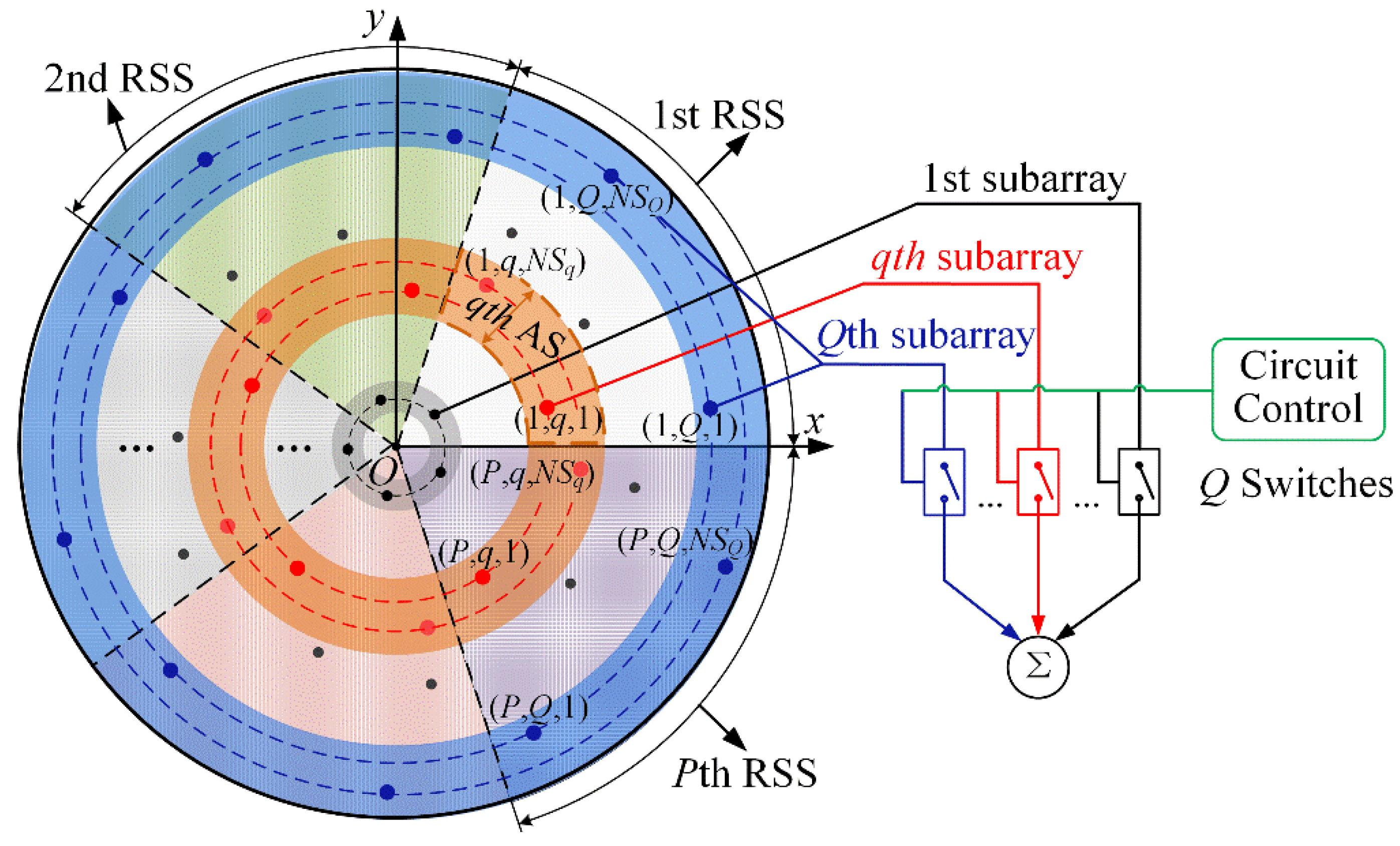
As shown in
Figure 1, the TMSCA has the same geometry as the RSSCA in [
18], where
N uniformly excited isotropic radiating elements arbitrarily distributed in
xoy plane. The arrangement of elements and the use of RF switches are rotationally symmetric in the circular aperture, and the radiation pattern of the specific array is absolutely rotationally symmetric, according to [
18].
First, the aperture with radius R is partitioned into P rotationally symmetric slices (RSSs), while each RSS is partitioned into Q annular sectors (ASs). The full array is composed of P RSS-arrays, and each RSS-array is composed of Q subarrays. The qth subarray has NSq elements distributed over the qth AS, q = 1, 2,…, Q, and = = .
Then,
Q high speed RF switches are controlled by a programmed circuit board and used in the TMSCA. The time modulation frequency and time modulation period are
fTM and
TTM (
fTM = 1/
TTM), respectively. The
qth subarray of each RSS-array is controlled by the
qth switch with a specific time sequence
Uq(
t),
q = 1, 2,…,
Q.
Suppose element (p, q, n) denotes the nth element of the qth subarray in the pth RSS-array (p = 1, 2,…, P, q = 1, 2,…, Q, n = 1, 2,…, NSq). In the polar coordinate system, (rq,n, ωq,n+(p−1)∙Δφ) is the location of element (p, q, n), and Δφ = 2π/P.
On the one hand, suppose the TMSCA with
N elements and
Q switches operates at frequency
f0, then the radiation pattern can be formulated as Equation (2a). On the other hand, suppose there is a single element at the center and controlled by an independent switch. The corresponding radiation pattern of the TMSCA with
N+1 elements and
Q+1 switches can be formulated as Equation (2b).
where
θ and
φ are the elevation and azimuth angles.
k is the free space wavenumber corresponding to the operating frequency
f0.
The time sequence
Uq(
t) in time domain can be decomposed into Fourier series in frequency domain, which can be expressed as
From Equations (2) and (3), the radiation pattern
f (
θ,
φ,
t) can be expanded into Fourier series and formulated as
where
Equations (5a) and (5b) denote the radiation patterns at the
hth order sideband frequency
f0 +
hfTM for the TMSCAs with
N and
N+1 elements, respectively. The directivity
Dir0 at
f0 is given by
where (
θ0,
φ0) denotes the direction of the maximum radiation at the operating frequency
f0.
2.2. Synthesis Procedure
In the TMSCA synthesis, the element number in each AS, all the element positions in the first RSS, and the time sequences of switches are jointly optimized. The optimization goal is to obtain the desired radiation pattern at the operating frequency f0 and suppress the sideband radiation.
Define the time sequence vector
T = (
τ1,
τ2,…,
τQ) (array without center element) or
T = (
τ0,
τ1,
τ2,…,
τQ) (array with a center element). The number vector
NS, the location vectors
r and
ω can be defined refer to [
18].
PSLL(
NS,
r,
ω,
T) and
ND(
NS,
r,
ω,
T) denote the peak sidelobe level and the null depth in the specific directions at the operating frequency
f0.
SBL(
NS,
r,
ω,
T) denotes the peak sideband level at the first order sideband frequency
f0+
fTM. Then, the optimization problem can be formulated as follows.
where
q = 1, 2,…,
Q,
n = 1, 2,…,
NSq,
k = 1, 2,…,
Q,
l = 1, 2,…,
NSk. And (
q −
k)
2 + (
n −
l)
2 ≠ 0.
SBLd denotes the desired sideband level.
NDd denotes the desired null depth value. Multiple constraints are taken into account, such as the total number of elements in each RSS (
NP), the aperture size (
R), and the minimum spacing (
dmin).
Based on the defined complicated projection process (refer to the Equations (4-11) in [
18]), vectors
NS,
r, and
ω can be calculated by the defined vectors
M,
d,
Δ, and
δ (refer to the Equation (8) in [
18]), which can be denoted as follows.
With (8), any set of (
M,
d,
Δ,
δ) can be projected to a feasible solution (
NS,
r,
ω). And the complicated constrained problem (7) can be transformed into a simple constrained problem with only box constraints.
where
q = 1, 2,…,
Q,
n = 1, 2,…,
Nq. Problem (9) is a nonconvex problem with respect to the variable set of (
M,
d,
Δ,
δ,
T).
By separately optimizing (
M,
d,
Δ,
δ) and
T, problem (9) can be decomposed into a nonconvex subproblem and a convex subproblem. For any determined set of (
M0,
d0,
Δ0,
δ0), the nonconvex problem (9) is equivalent to a convex subproblem with respect to
T.
where
NS0 =
g1(
M0),
r0 =
g2[
NS0,
d0,
Δ0],
ω0 =
g3[
NS0,
δ0].
The synthesis problem (9) is solved by the HS-CP algorithm in two dependent optimizations. First, the nonconvex subproblem with respect to (
M,
d,
Δ,
δ) is solved by the harmony search algorithm [
12], which is a metaheuristic method. Based on the obtained optimal set of (
M*,
d*,
Δ*,
δ*), problem (9) is transformed into the subproblem (10). Then, the convex subproblem with respect to
T can be efficiently solved by the convex optimization tool box.
3. Numerical Results
In this section, two TMSCAs with 256 and 600 isotropic radiating elements are synthesized. Array geometry and radiation properties are analyzed. The control parameters of the hybrid harmony search-convex programming algorithm are set as follows. The harmony memory size is 50, the harmony memory considering rate is 0.9, the pitch adjusting rate is 0.3, the width of adjustment is 0.1, and the maximum number of iterations is 500. For all computer simulations, 10 independent runs are performed. A readily available MATLAB toolbox named CVX [
21] with a MOSEK solver [
22] is used. All the simulations are carried out through MATLAB R2018b on a computer with i7-9700K, 3.6 GHz processor and 32 GB RAM.
3.1. Low Sidelobe Pattern With Suppressed Sideband
Design A is a 256-element TMSCA with a single element at the center. Set
P = 5, and
Q = 9. To contrast with the optimized TMCCAs (Case 1 and Case 2) in [
10], the minimum element spacing
dmin is set as 0.5
λ, and the aperture radius
R is set as 6.5
λ. The 256-element TMSCA with 10 RF switches (for the center element and 9 subarrays) is optimized by the HS-CP algorithm to obtain low sidelobe pattern at the operating frequency and suppress the first order sideband radiation. The desired sideband level
SBLd is set as −30 dB.
The optimized switching time sequences (
τp/
TTM) of Case 1, Case 2 and Design A are given in
Table 1. Case 1 and Case 2 has been synthesized by the CSO algorithm in [
10]. Some geometry and radiation properties of two cases and Design A are listed and compared in
Table 2. Case 1 only optimized switching time sequence. The 9-ring TMCCA of 279 elements has the
PSLL of –28.02 dB and the
SBL of –4.56 dB, respectively. For Case 2, switching time sequence, ring radii, and element spacing are optimized simultaneously. The element numbers in the 9 rings are 8, 15, 18, 23, 28, 35, 41, 41, and 47. The 9-ring TMCCA of 256 elements has the
PSLL of –36.02 dB and the
SBL of –8.06 dB.
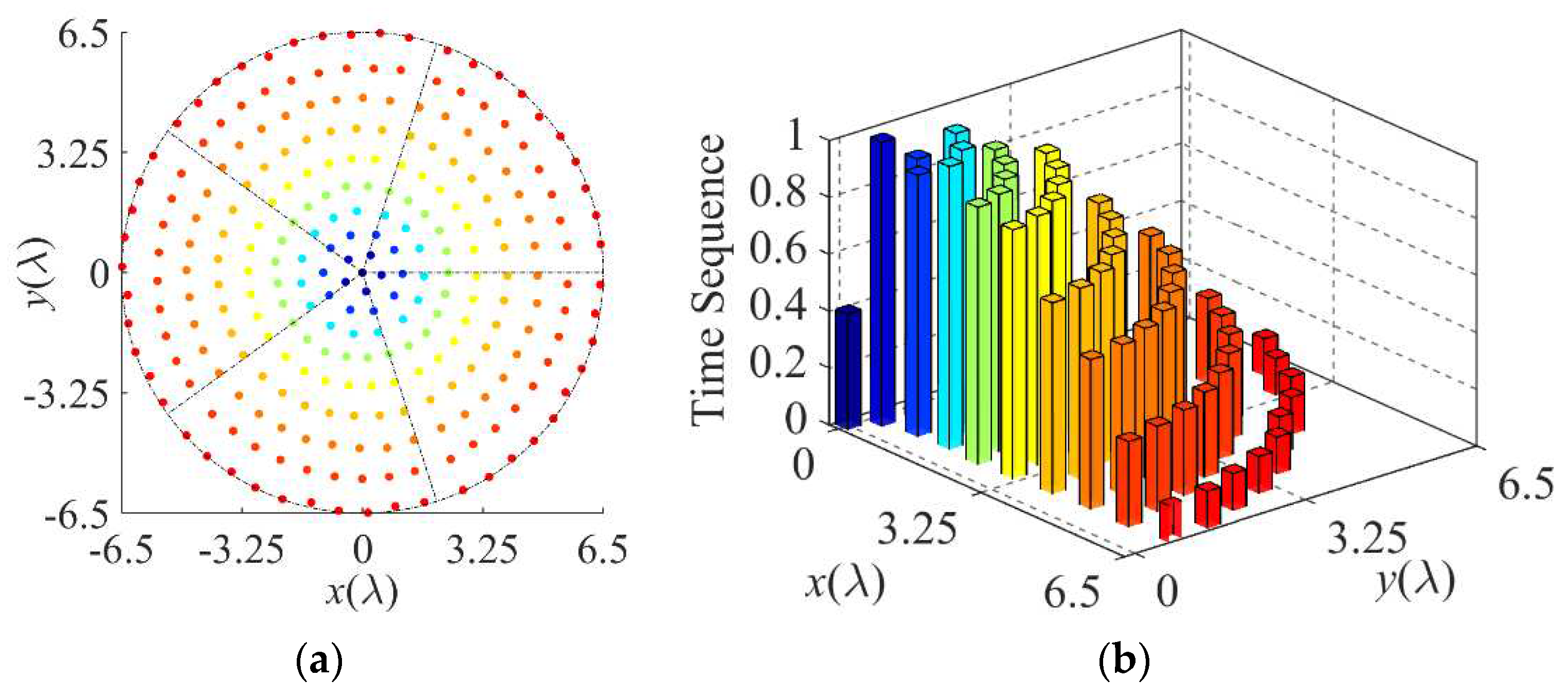
The array layout and normalized switch-on time sequence of Design A are shown in
Figure 2(a) and 2(b), respectively. The element numbers (
NSq) in the 9 subarrays are 1, 2, 3, 5, 6, 7, 8, 9, and 10.
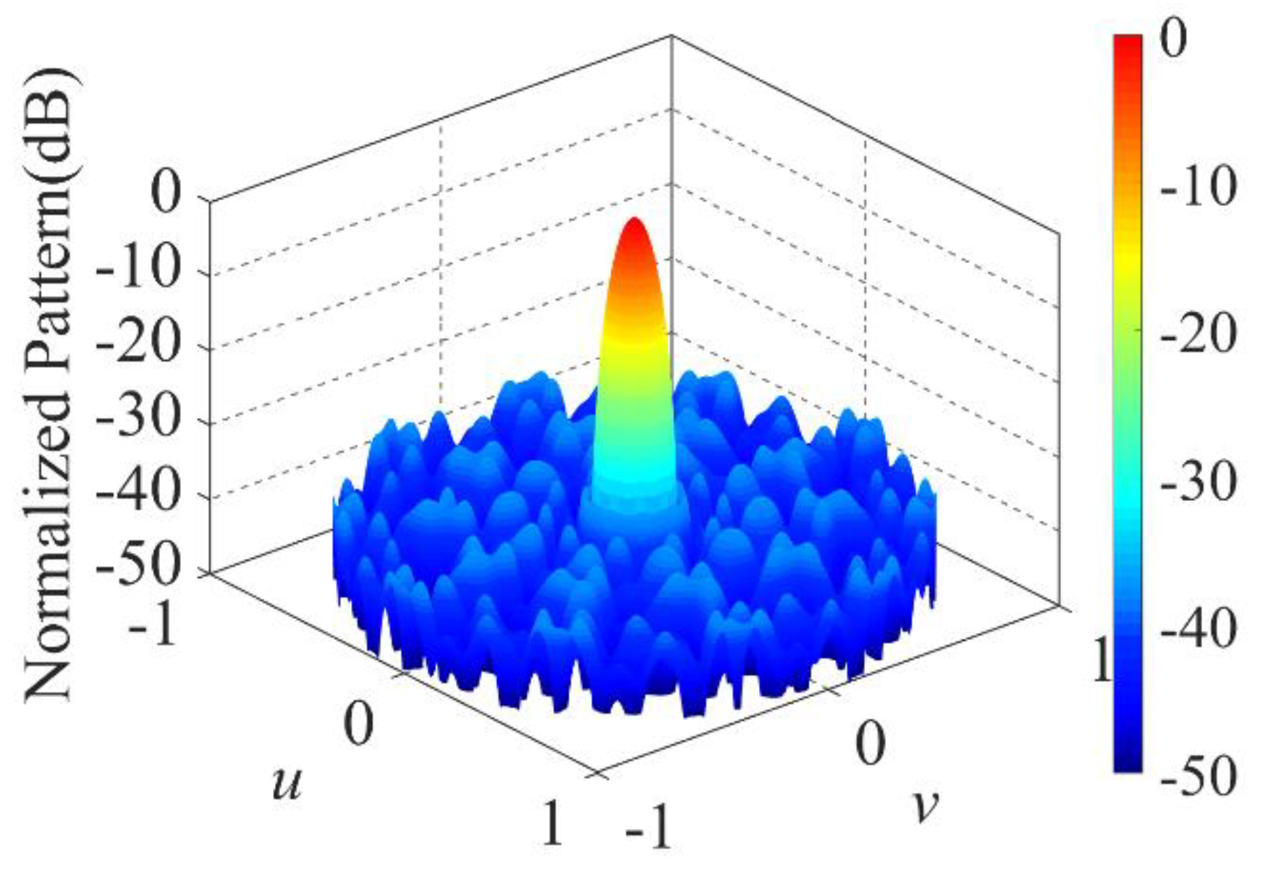
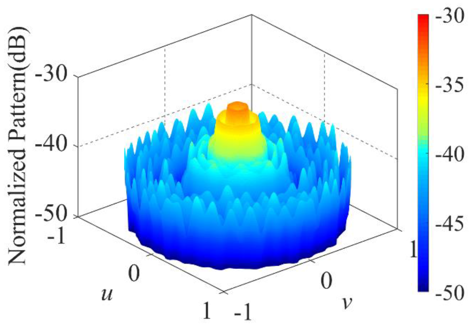
Figure 3 and
Figure 4 show the normalized pattern at the operating frequency and the normalized pattern at the first order sideband frequency, respectively. With the comparison to Case 1 and Case 2, the optimized Design A provides much lower
PSLL and
SBL, with a little decrease in FNBW. Design A provides the
PSLL of –36.71 dB. Less than –33.21 dB
SBL is obtained, which is 28.65 dB and 25.15 dB lower than that of Case 1 and Case 2. The directivities at the operating frequency of Case 1, Case 2 and Design A are 27.11 dB, 29.72 dB, 30.24 dB, respectively. The FNBWs at the operating frequency of Case 1, Case 2 and Design A are 18
°, 17.6
°, 16.8
°, respectively.
3.2. Low Sidelobe-2D Null Pattern With Suppressed Sideband
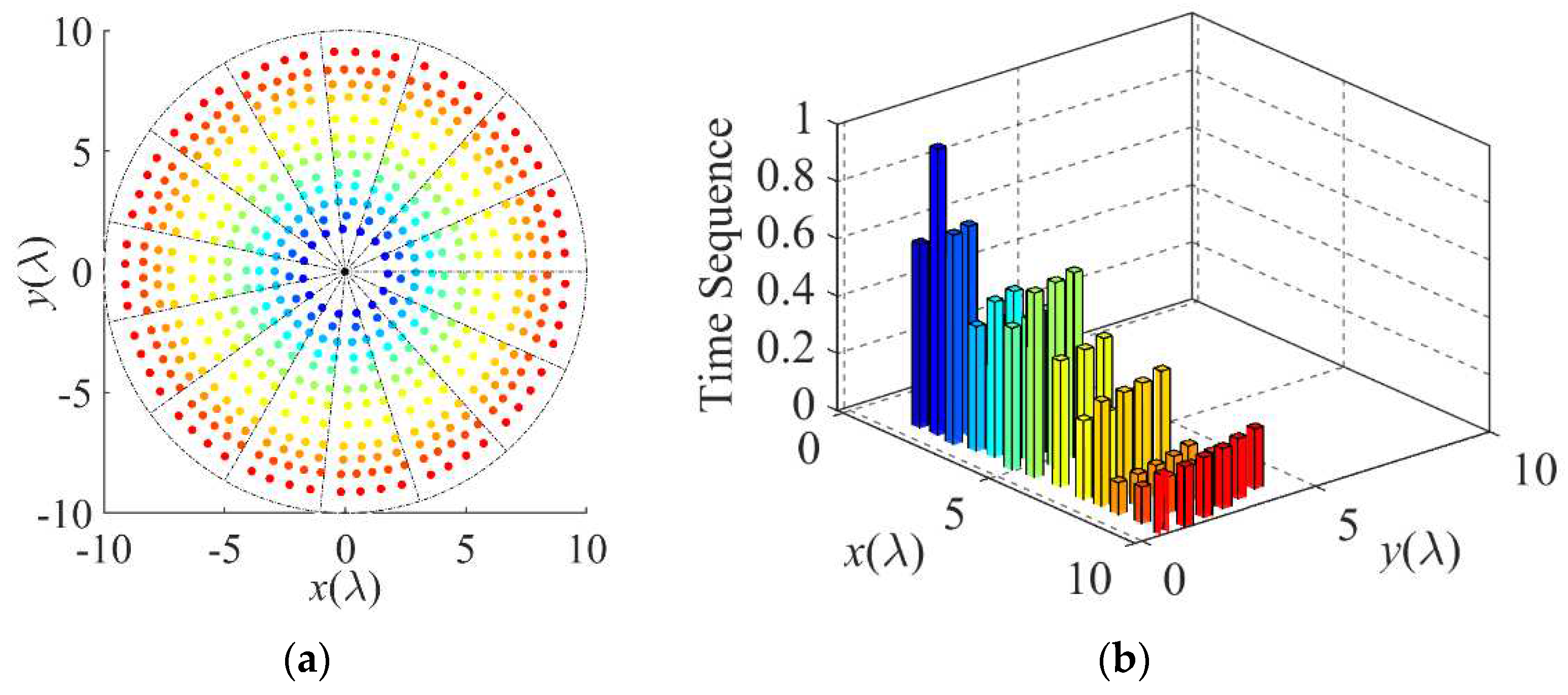
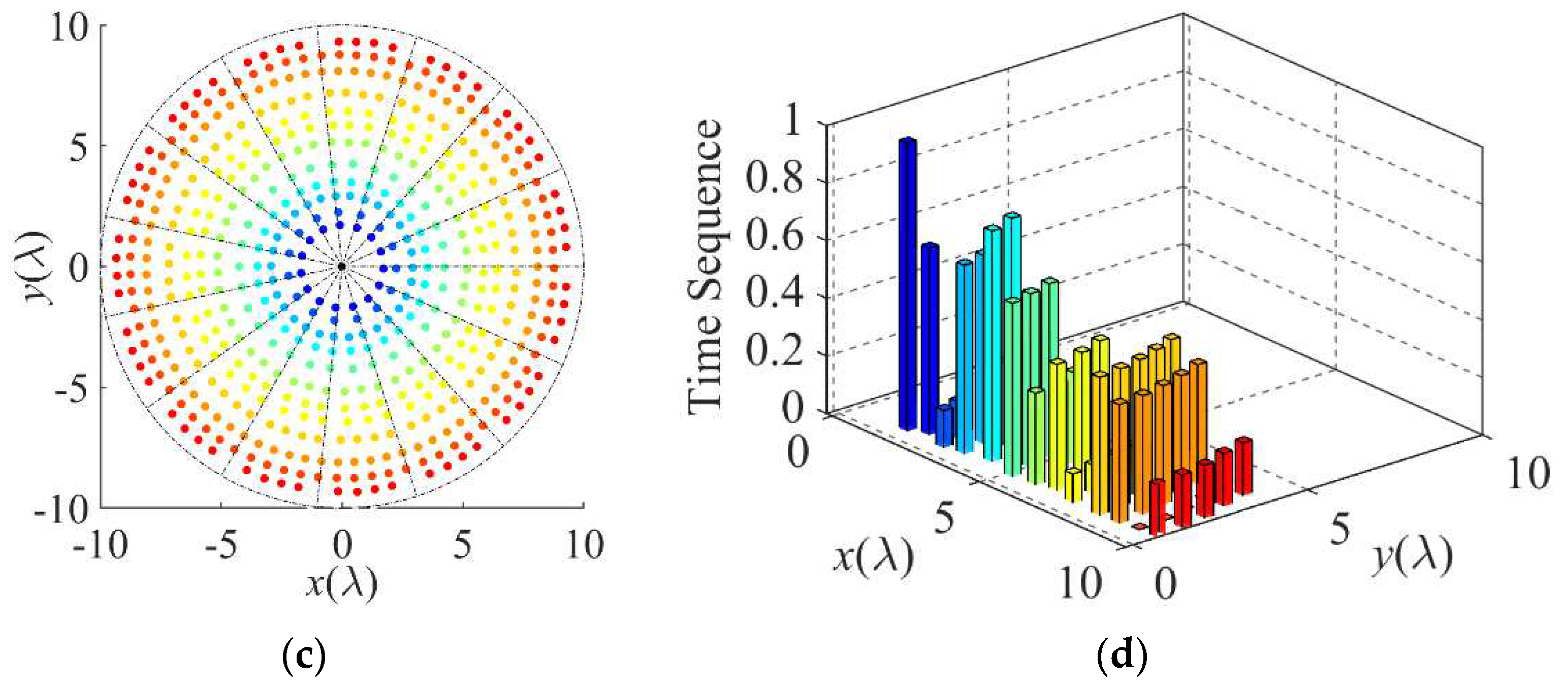
Design B is a 600-element TMSCA with P = 15, Q = 15. The optimization goal is to obtain the radiation pattern with low sidelobe level and null depth in the specific 2D directions, while suppress the first order sideband radiation. The minimum element spacing, the aperture radius, the desired sideband level, and the desired null depth are set as follows: dmin = 0.5λ, R = 10λ, SBLd = −20 dB, NDd = −40 dB.
Two cases are discussed with the desired wide 2D null directions (
θND,
φND) for 0° ≤
φND ≤ 360°, with 35° ≤
θND ≤ 50° (Design B1), and 0° ≤
φND ≤ 360°, with 45° ≤
θND ≤ 50° as well as 65° ≤
θND ≤ 75° (Design B2). Design B1 and Design B2 are synthesized by optimizing the array geometry and the time sequence, and results are shown in
Figure 5. The optimized element number and switching time sequence in each subarray are listed in
Table 3. Some important geometry and radiation properties of two cases are summarized in
Table 4.
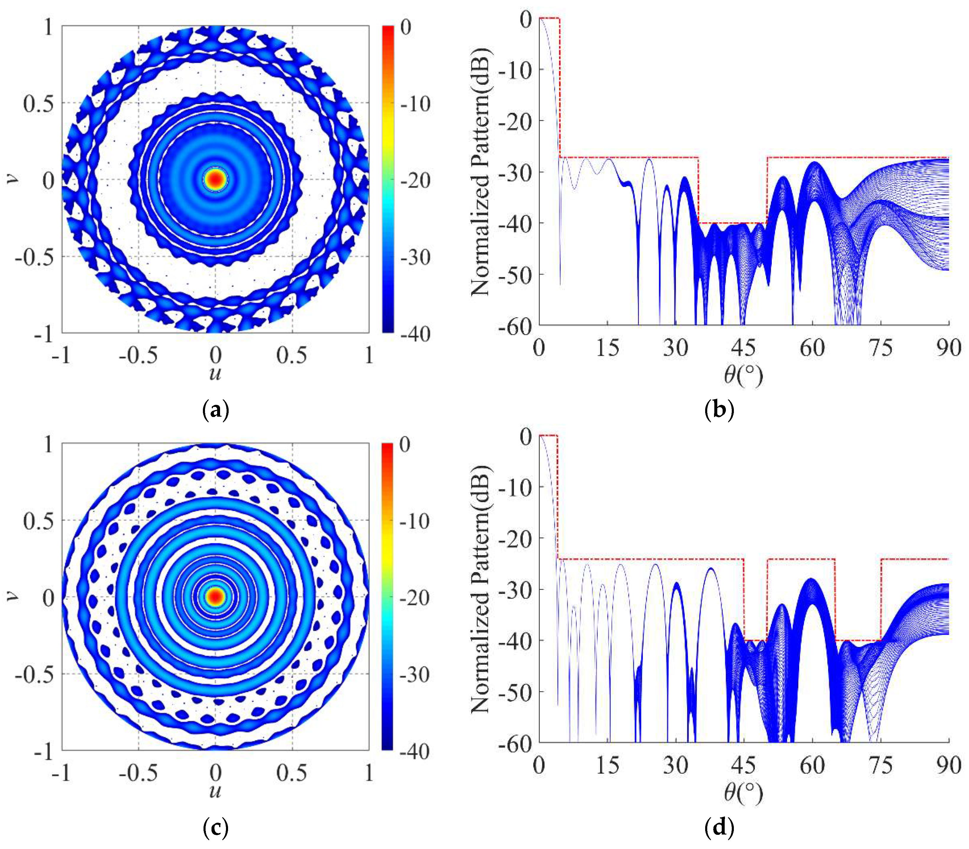
Figure 6(a) and 6(b) show the corresponding 3-D radiation pattern and the cuts of patterns in all
φ planes of Design B1. For Design B1, the radiation pattern at the operating frequency have the
PSLL of –27.22 dB. In all
φ planes (0° ≤
φND≤ 360°), the null depths in directions of 35° ≤
θND ≤ 50° are less than −40 dB, which meet the predesigned specifications. The directivity and FNBW at the operating frequency are 32.55 dB and 9.2
°, respectively. The first order sideband pattern with the
SBL of –22.62 dB is obtained.
Figure 6(c) and 6(d) show the corresponding 3-D radiation pattern and the cuts of patterns in all
φ planes of Design B2. For Design B2, the radiation pattern at the operating frequency have the
PSLL of –24.22 dB. In all
φ planes (0° ≤
φND≤ 360°), the null depths in directions of 45° ≤
θND ≤ 50° and 65° ≤
θND ≤ 75° are less than −40 dB, which meet the predesigned specifications. The directivity and FNBW at the operating frequency are 32.71 dB and 8
°, respectively. The first order sideband pattern with the
SBL of –24.34 dB is obtained.
4. Conclusions
In this paper, the new type of time-modulated sparse circular array with rotationally symmetric structure is synthesized by the HS-CP algorithm. With multiple constraints (the total number of elements in each rotationally symmetric slice, the aperture size, the minimum element spacing) taken into account, the synthesis problem is analyzed and divided into two dependent optimizations. The array geometry and the time sequences of RF switches are optimized separately. Two designs are optimized and the numerical results indicate that our TMSCA is capable of achieving relatively low sidelobe level, deep null level in a wide two-dimensional directions, suppressed sideband level, and improved directivity.
Author Contributions
Conceptualization, Rui-Qi Wang and Wenyuan Liu; Data curation, Lei Wang and Zhe Wu; Formal analysis, Wenyuan Liu; Investigation, Duan Nie; Methodology, Rui-Qi Wang; Resources, Ling Sun and Yu Yun; Software, Duan Nie; Validation, Duan Nie and Rui-Qi Wang; Writing – original draft, Rui-Qi Wang; Writing – review & editing, Rui-Qi Wang.
Funding
This research was supported by the Natural Science Foundation of China (NSFC) under Grant No. 62201335, and the Foundation of Shaanxi Provincial Department Education under Grant No. 23JK0342.
Data Availability Statement
The data presented in this study are available upon request from the corresponding author.
Conflicts of Interest
The authors declare that the research was conducted in the absence of any commercial or financial relationships that could be construed as a potential conflict of interest.
References
- Zhu, Q.; Yang, S.; Zheng, L.; Nie, Z. Design of a low sidelobe time modulated linear array with uniform amplitude and sub-sectional optimized time steps. IEEE Trans. Antennas Propag. 2012, 60, 4436–4439. [Google Scholar] [CrossRef]
- Gassab, O.; Azrar, A.; Dahimene, A.; Bouguerra, S. Efficient mathematical method to suppress sidelobes and sidebands in time-modulated linear arrays. IEEE Antennas Wireless Propag. Lett. 2019, 18, 836–840. [Google Scholar] [CrossRef]
- Chakraborty, A.; Ram, G.; Mandal, D. Optimal pulse shifting in timed antenna array for simultaneous reduction of sidelobe and sideband level. IEEE Access 2020, 8, 131063–131075. [Google Scholar] [CrossRef]
- Mandal, S.; Mandal, S. K. Synthesis of time-modulated array with reduced sideband radiation by increasing main-beam maximum. IEEE Antennas Wireless Propag. Lett. 2023, 22, 342–346. [Google Scholar] [CrossRef]
- Hei, Y. Q.; Ma, L. Y.; Li, W. T.; Mou, J. C.; Shi, X. W. Effective artificial neural network framework for time-modulated arrays synthesis. IEEE Trans. Antennas Propag. 2023, 71, 7728–7740. [Google Scholar] [CrossRef]
- Zhang, Y.X.; Jiao, Y.-C.; Zhang, L. Efficient directivity maximization of time modulated arrays with two-stage convex optimization. IEEE Antennas Wireless Propag. Lett. 2020, 19, 1847–1851. [Google Scholar] [CrossRef]
- Yang, J.; Li, W.; Shi, X.; Li, X.; Yu, J. A hybrid ABC-DE algorithm and its application for time-modulated arrays pattern synthesis. IEEE Trans. Antennas Propag. 2013, 61, 5485–5495. [Google Scholar] [CrossRef]
- Guney, K.; Basbug, S. Null synthesis of time-modulated circular antenna arrays using an improved differential evolution algorithm. IEEE Antennas Wireless Propag. Lett. 2013, 12, 817–820. [Google Scholar] [CrossRef]
- Jiang, Z. J.; Zhao, S.; Chen, Y.; Cui, T. J. Beamforming optimization for time-modulated circular-aperture grid array with DE algorithm. IEEE Antennas Wireless Propag. Lett. 2018, 17, 2434–2438. [Google Scholar] [CrossRef]
- Ram, G.; Mandal, D.; Kar, R.; Ghoshal, S. P. Cat swarm optimization as applied to time-modulated concentric circular antenna array: analysis and comparison with other stochastic optimization methods. IEEE Trans. Antennas Propag. 2015, 63, 4180–4183. [Google Scholar] [CrossRef]
- Wang, R.-Q.; Yun, Y.; Sun, L.; Wu, Z.; Tan, X. Synthesis of time-modulated sparse circular arrays with low sidelobes and suppressed sidebands. In Proceedings of the 11th Asia-Pacific Conference on Antennas and Propagation (APCAP 2023), Guangzhou, China, 19-22 November 2023. [Google Scholar]
- Portilla-Flores, E. A.; Sanchez-Marquez, A.; Flores-Pulido, L.; Vega-Alvarado, E.; Calva Yanez, M. B.; Aponte-Rodriguez, J. A.; Nino-Suarez, P. A. Enhancing the harmony search algorithm performance on constrained numerical optimization. IEEE Access 2017, 5, 25759–25780. [Google Scholar] [CrossRef]
- Cui, Y.; Dong, W.; Hu, D.; Liu, H. The application of improved harmony search algorithm to multi-UAV task assignment. Electronics 2022, 11, 1171. [Google Scholar] [CrossRef]
- Haupt, R. L. Optimized element spacing for low sidelobe concentric ring arrays. IEEE Trans. Antennas Propag. 2008, 56, 266–268. [Google Scholar] [CrossRef]
- Yi, J.; Zhang, S.; Guo, Q.; Luan, X. A hybrid strategy based on weighting density and genetic algorithm for the synthesis of uniformly weighted concentric ring arrays. IEEE Antennas Wireless Propag. Lett. 2017, 16, 186–189. [Google Scholar] [CrossRef]
- Chen, K.; Chen, H.; Wang, L.; Wu, H. Modified real GA for the synthesis of sparse planar circular arrays. IEEE Antennas Wireless Propag. Lett. 2016, 15, 274–277. [Google Scholar] [CrossRef]
- Gregory, M. D.; Namin, F. A.; Werner, D. H. Exploiting rotational symmetry for the design of ultra-wideband planar phased array layouts. IEEE Trans. Antennas Propag. 2013, 61, 176–184. [Google Scholar] [CrossRef]
- Wang, R.-Q.; Jiao, Y.-C. Synthesis of wideband rotationally symmetric sparse circular arrays with multiple constraints. IEEE Antennas Wireless Propag. Lett. 2019, 18, 821–825. [Google Scholar] [CrossRef]
- Wang, R.-Q.; Jiao, Y.-C. Multiple-constraint synthesis of rotationally symmetric sparse circular arrays using a hybrid algorithm. Prog. Electromagn. Res. M 2019, 79, 33–40. [Google Scholar] [CrossRef]
- Liu, F.; Wen, P.; Zhang, C.; Wang, L.; Xu, K. Synthesis of large ultra-wideband sparse circular planar arrays based on rotationally symmetric structure. Electronics 2023, 12, 4833. [Google Scholar] [CrossRef]
- CVX: MATLAB Software for Disciplined Convex Programming, version 2.0. Available online: http://cvxr.com/cvx.
- The MOSEK Optimization Toolbox for MATLAB Manual, version 10.1.21. Available online: https://www.mosek.com/downloads/.
|
Disclaimer/Publisher’s Note: The statements, opinions and data contained in all publications are solely those of the individual author(s) and contributor(s) and not of MDPI and/or the editor(s). MDPI and/or the editor(s) disclaim responsibility for any injury to people or property resulting from any ideas, methods, instructions or products referred to in the content. |
© 2024 by the authors. Licensee MDPI, Basel, Switzerland. This article is an open access article distributed under the terms and conditions of the Creative Commons Attribution (CC BY) license (http://creativecommons.org/licenses/by/4.0/).
