Preprint
Article

Asymmetries Caused by Nonparaxiality and Spin-Orbit Interaction during Light Propagation in a Graded-Index Medium

Altmetrics

Downloads

83

Views

19

Comments

0

A peer-reviewed article of this preprint also exists.

This version is not peer-reviewed

Submitted:

08 December 2023

Posted:

11 December 2023

You are already at the latest version

Alerts
Abstract
Spin-orbit coupling and nonparaxiality effects during propagation of vortex vector light beams in a cylindrical graded-index waveguide are investigated by solving the full three-component field Maxwell’s equations. Symmetry breaking effects for left- and right-handed circularly polarized vortex light beams propagating in a rotationally symmetric graded-index optical fiber are considered. The mode-group delay in a graded-index fiber due to spin-orbit interaction is demonstrated. It is shown that the relative delay times between vortex pulses of opposite circular polarizations of the order of 10 ps/km can be observed in graded-index fibers for high-order topological charges.
Keywords: 
Subject: Physical Sciences  -   Optics and Photonics

1. Introduction

Various symmetry breaking effects arise at the propagation of a polarized light in dielectric media. Different transmission levels for left and right-hand circular polarizations (circular dichroism) exhibit optically active materials. Conventional optical activity is associated with intrinsically 3D-chiral molecules, and it is the property of unequal absorption of right and left hand circular polarized light. In [1,2] directionally asymmetric transmission of polarized light in planar chiral structures was considered. Optical activity may also arise from extrinsic chirality. Strong optical activity and circular dichroism in non-chiral planar microwave and photonic metamaterials was demonstrated in [3]. It is well known that, when a light beam is reflected from an interface, the longitudinal shift of the gravity center of the beam is different for s- and p-polarized beams [4], while the transverse shift has reverse signs in the case of right- and left-hand circularly polarized radiation [5]. Lateral and angular shifts for strongly focused azimuthally and radially polarized beams at a dielectric interface were shown in [6]. Polarization-dependent light transmission occurs in a filter with frustrated total internal reflection (FTIR) due to different resonance conditions for incident beams with s- and p- polarization [7,8]. Recently, a phenomenon of spin-dependent splitting of the focal spot of a plasmonic focusing lens was demonstrated experimentally [9,10]. Polarization-dependent splitting of the reflected beam from the surface of the subwavelength grating was also shown in [11,12]. The effect of spin symmetry breaking via spin-orbit interaction, which occurs even in rotationally symmetric structures, was observed in plasmonic nanoapertures [13]. Similar effect of polarization-dependent transmission through subwavelength round and square apertures was demonstrated in [14].
Polarization-dependent symmetry breaking effects occur also for a light propagating in optical waveguides. It is known that the polarization plane in an inhomogeneous medium is rotated on propagation of light ray on the helical trajectory [15,16]. Such rotation was observed experimentally in a single mode optical fiber wound on a cylinder [17] and interpreted in terms of Berry's geometrical phase [18]. In [19] the rotation of the polarization plane was observed also in a straight multimode fiber with step-index-type profile. It is of interest also to consider the inverse effect, i.e., the influence of polarization on the trajectory and the width of a radiation beam. As demonstrated in [20], these effects can be also observed in optical fibers, where small shifts are accumulated due to multiple reflections in the process of radiation propagation through a fiber. The authors of [20] calculated the rotation of the speckle pattern produced by circularly polarized light at the output of a fiber corresponding to the reversal of the sign of circular polarization. In [21] it was experimentally demonstrated that the rotation angle of the speckle pattern depends on the angle at which a circularly polarized light beam is coupled into a fiber. It was shown in [22,23] that spin-orbit interaction causes asymmetry effect for depolarization of the right- and left-handed circularly polarized light propagating in a graded-index (GRIN) fiber. Depolarization is stronger if the helicity of the trajectory of rays and photons has the same sign, and less if they do not coincide. Spin-dependent relative shift between right- and left-hand circularly polarized light beams propagating along a helical trajectory in a graded-index fiber was shown in [24,25]. In [26] this effect was observed experimentally for a laser beam propagating in the glass cylinder along the smooth helical trajectory. This shift can be regarded as a manifestation of the optical Magnus effect [27] and the optical spin-Hall effect [28,29] which arises due to a spin-orbit coupling. Propagation of light beams in a graded-index medium is mainly investigated in the paraxial approximation. Both ray and wave optics is applied for the analysis of light propagation in graded-index media [30–42]. Effects of the polarization on the modes in lens-like media were analyzed in [43]. In [44] the polarization-dependent Goos-Hanchen (GH) beam shift at a graded-index dielectric interface is examined both theoretically and experimentally. In [45] the beam shifts or corrections with respect to geometrical optics caused by the nonparaxiality and spin-orbit interaction in a graded-index optical fiber are investigated.
In this paper, the effect of symmetry breaking for left- and right-handed circularly polarized light in an isotropic graded-index fiber due to spin-orbit interaction forces is demonstrated analytically by solving the full three-component field Maxwell’s equations.  It is shown that the propagation velocities of vortex modes with right- and left- handed polarizations differ from each other due to spin-orbit interaction.

2. Basic equations

The Maxwell equations for the electric field E exp ( i ν t ) in a general inhomogeneous medium with dielectric constant ε(x, y) reduce to:
2 E + k 2 n 2 E + E ln n 2 = 0 ,
where k = 2 π / λ  is the wavenumber and ε = n 2  is the dielectric permittivity of the medium.
In the paraxial approximation, equation (1) can be reduced to the equivalent time-independent Schrodinger equation [46]. An analogous approach may be used to obtain a parabolic equation for the two-component vector field wavefunction [22–24]. Using the same method, the equation for a three-component wave equation can be derived:
i k Ψ z = H ̑ Ψ ,
where
Ψ = n 0 1 / 2 exp ( i k n 0 z ) e x r , ϕ e y r , ϕ e z r , ϕ ,   H ̑ = Ζ ̑ 1 H ̑ 0 + H ̑ 1 = H ̑ 0 + H ̑ 1 + H ̑ 2 ,
H ̑ 0 = 1 2 k 2 n 0 2 r 2 + 1 r r + 1 r 2 2 ϕ 2 + 1 2 n 0 n 0 2 n 2 I ̑
is the unperturbed Hamiltonian corresponding to the first two terms in the equation (1),
H ̑ 1 = 1 2 k 2 n 0 x cos ϕ ln n 2 r x sin ϕ ln n 2 r 0 y cos ϕ ln n 2 r y sin ϕ ln n 2 r 0 0 0 0
and H ̑ 2 = Z ̑ 1 1 H ̑ 0  are the perturbations corresponding to the third term in the equation (1),
Z ̑ 1 = 1 0 0 0 1 0 i 2 k n 0 ln n 2 x i 2 k n 0 ln n 2 y 1 = I ̑ + Z ̑ 1 1 ,
Consider a rotationally symmetric cylindrical waveguide with a parabolic distribution of the refractive index:
n 2 ( r ) = n 0 2 ω 2 r 2 ,
where n0 is the refractive index on the waveguide axis, ω is the gradient parameter, r = x 2 + y 2 .
The Hamiltonian H ̑  may be rewritten in terms of annihilation and creation operators [36]:
A ̑ 1,2 = 1 2 a ̑ 1 ± i a ̑ 2 , A ̑ 1,2 + = 1 2 a ̑ 1 + i a ̑ 2 + , a ̑ 1 = 1 2 k ω x ̑ + i k ω p ̑ x , a ̑ 2 = 1 2 k ω y ̑ + i k ω p ̑ y , p ̑ x = i k x , p ̑ y = i k y ,
( x , y ) = ( r cos ϕ , r sin ϕ ) , x = cos ϕ r sin ϕ r ϕ , y = sin ϕ r + cos ϕ r ϕ .
These operators satisfy the commutation relations: a ̑ i , a ̑ j + = δ i j , A ̑ i , A ̑ j + = δ i j .
Thus, we have
H ̑ 0 = ω k n 0 A ̑ 1 + A ̑ 1 + A 2 + A ̑ 2 + 1 I ̑ ,
H ̑ 1 = η c 1 1 + 1 2 σ ̑ z 1 2 σ ̑ z 2 + c 2 1 2 σ ̑ z + 3 2 σ ̑ z 2 1 + c 3 σ ̑ z σ ̑ + σ ̑ σ ̑ z + с 4 σ z σ + + σ σ z ,
H ̑ 2 = h σ ̑ 2 + 1 2 s σ ̑ σ ̑ σ ̑ z σ ̑ z σ ̑ H ̑ 0
Here
c 1 = 1 ̑ + A ̑ 1 A ̑ 2 A ̑ 1 + A ̑ 2 + , c 2 = 1 2 A ̑ 1 2 A ̑ 1 + 2 + A ̑ 2 2 A ̑ 2 + 2 , c 3 = i k L ̑ z , c 4 = i 2 A ̑ 1 2 + A ̑ 1 + 2 A ̑ 2 2 A ̑ 2 + 2 , h = i ξ A ̑ 1 + A ̑ 1 + + A ̑ 2 + A ̑ 2 + , s = ξ A ̑ 1 + A ̑ 1 + A ̑ 2 A ̑ 2 + , η = ω 2 2 k 2 n 0 3 , ξ = 1 2 ω k 3 / 2 1 n 0 3 , L ̑ z = i k ϕ = 1 k A ̑ 2 + A ̑ 2 A ̑ 1 + A ̑ 1 , I ̑ = 1 0 0 0 1 0 0 0 1  is the unit matrix and σ ̑ x = 1 2 0 1 0 1 0 1 0 1 0 , σ ̑ y = 1 2 0 i 0 i 0 i 0 i 0 , σ ̑ z = 1 0 0 0 0 0 0 0 1 , σ ̑ + = 1 2 σ ̑ x + i σ ̑ y , σ ̑ = 1 2 σ ̑ x i σ ̑ y .
Representation of the Hamiltonian by means of the operators will allow us to calculate the matrix elements analytically. Note that generalized Stokes vectors consisting of nine real parameters in terms of vector and tensor operators are considered to completely describe three-dimensional fields [47] .
The solution of the unperturbed equation is described by radially symmetric Laguerre-Gauss functions ψ v l ( r , ϕ ) = v , l :
ψ v l ( r , ϕ ) = k ω π 1 2 p ! ( p + l ) ! 1 2 k ω r 2 l 2 exp k ω r 2 2 L p l k ω r 2 exp ( i l ϕ ) ,
where v = 2 p + l  is the principal quantum number, p and l  are the radial and azimuthal indices, accordingly, and l = v , v 2 , v 4 , . . . 1  or 0, ω = 2 / ( k w 0 2 ) , w 0  is the radius of the fundamental mode.
The numbers v  and l  express the eigenvalues of the unperturbed Hamiltonian H ̑ 0 v , l = ω / k n 0 2 v + 1 v , l , and eigenvalues L = l / k  of the angular momentum operator L ̑ z v , l = l / k v , l .
It was shown in [36,39] that the hybrid wave functions consisting of transverse and longitudinal components are the solutions of the equation (2):
Ψ r , ϕ , 0 = v l i σ v l e z ,
where σ = + 1  and σ = 1  correspond to right-handed and left-handed circularly polarized beams, accordingly, and σ = 0  corresponds to the linear polarization.
The propagation constant, which takes into account non-paraxial terms of the first order, is given by the expression [39,48]:
β v l σ = k n 0 1 η v + 1 η 2 32 11 v + 1 2 j 2 2 j σ ,
where η = ω / k n 0 2 , n 0  is the refractive index on the waveguide axis, ω  is the gradient parameter, j = l + σ  is the total angular momentum, σ  is the spin angular momentum.
The term j σ  in (7) relates to the spin-orbit and spin-spin interactions.
Consider the incident vector vortex beams with right-circular and left-circular polarizations, accordingly: Ψ 0 + = v ' l , i v ' l , e z  and Ψ 0 = v ' l , i v ' l , e z , where v ' l  is given by (5), and ω ' = 2 / ( k a 0 2 ) , a 0  is the radius of a beam which is different from the radius of the fundamental mode of the medium w 0 = 2 / ( k ω ) .  
The arbitrary incident beam may be expanded into modal solutions, so the evolution of a beam in the medium (3) can be represented as
Ψ ( r , ϕ , z ) = v l σ a v l σ v l i σ v l ( i / k n 0 ) x + i σ y v l exp i β v l σ z ,
where a v l σ  are the coupling coefficients.
If the incident beam is described by the Laguerre-Gauss function Ψ v ' l ' σ * = 1 / 2 v ' l ' , i σ v ' l ' , e z * , the coupling coefficients a v l σ   can be calculated analytically:
v l σ v ' l σ = 2 ω ω ' ω + ω ' l + 1 ω ' ω ω ' + ω p p ' p ' ! p + l ! p ' + l ! p ! 1 2 P p ' p p ' , l ( t ) ,
where P p ' p p ' , l t are the Jacobi polynomials, t = 1 2 ω ' ω ω ' + ω 2 , ω ' = 2 / k a 0 2 , ω = 2 / k w 0 2 .

3. Simulation results

Below we consider the effects of asymmetry caused by nonparaxiality and spin-orbit interaction, when Laguerre-Gauss beams with different radial and azimuthal indices and polarization states propagate in a rotationally symmetric cylindrical waveguide with a parabolic distribution of the refractive index (3).

3.1. Effect of nonparaxiality on the beam width and axial intensity distribution

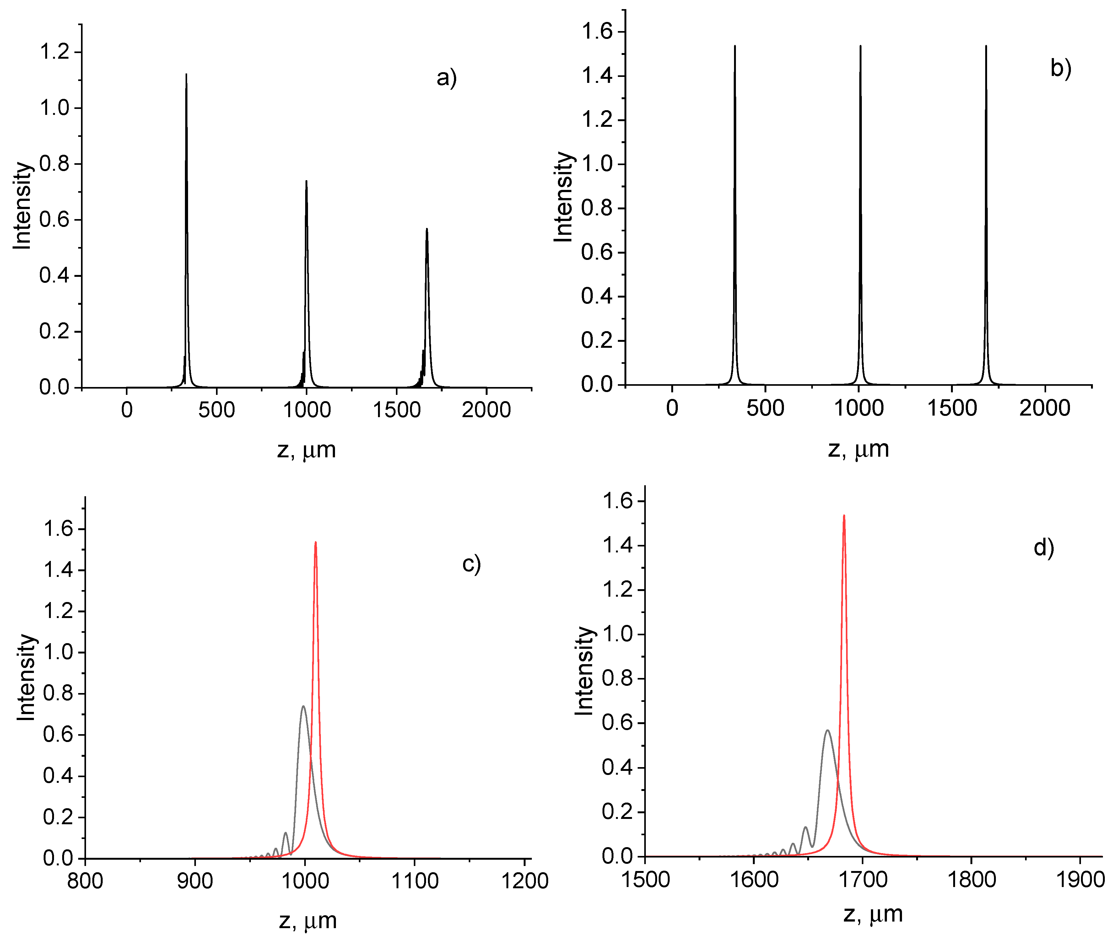
The effects of non-paraxiality are most evident when focusing the beam. It is known that nonparaxial effects significantly influence on the characteristics of a tightly focused beam [49,50,51,52,53,54,55]. In the paraxial approximation, focusing occurs periodically with a period z T = π n 0 ω . However, the focusing begins to weaken with increasing distance, if nonparaxial effects are considered (Figure 1). In addition, there is a shift in focus plane towards the source aperture, and this shift accumulates with distance and increases with increasing aperture size a 0 . Unlike the paraxial case, focusing ceases to be observed with increasing distance, i.e. the properties of self-imaging will decrease at a certain distance, determined by the degree of nonparaxiality η = a 0 / z T .
In Figure 2 the intensity distributions in axial direction of the transverse field component are presented for nonparaxial and paraxial cases. Simulations show that intensity oscillations in front of the focus plane occur due to interference between modes. Besides, the focal plane shift occurs when the nonparaxiality effects are considered (Figure 2c, 2d). This shift increases with aperture of incident beam and the degree of nonparaxiality.

3.2. Effect of spin-orbit interaction on the intensity distribution

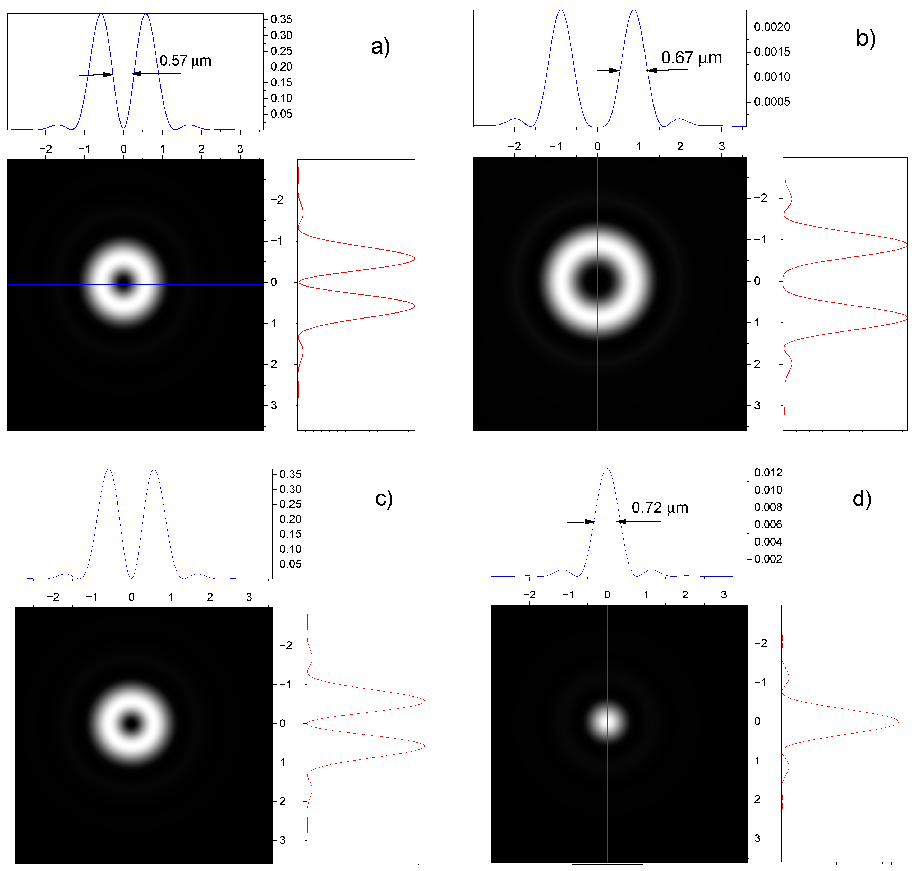
The intensity distributions in the transverse and longitudinal directions at different distances are determined by the functions I ( r , ϕ , z ) = ψ ( r , ϕ , z ) 2 and I z ( r , ϕ , z ) = e z ( r , ϕ , z ) 2 , accordingly. In Figure 3 the intensity profiles of the transverse and longitudinal field components in a focal plane z f are presented for the circularly polarized incident beams with radial index p = 0 and different azimuthal indices (topological charges). The waveguide (3) with the gradient parameter ω = 7 1 0 3   μ m 1 and the refractive index n 0 = 1.5 is considered. Here and below, the beams with wavelength λ = 0.63 μ m are considered. The initial beam width or the full width at half-maximum (FWHM) is a 0 = 45   μ m .
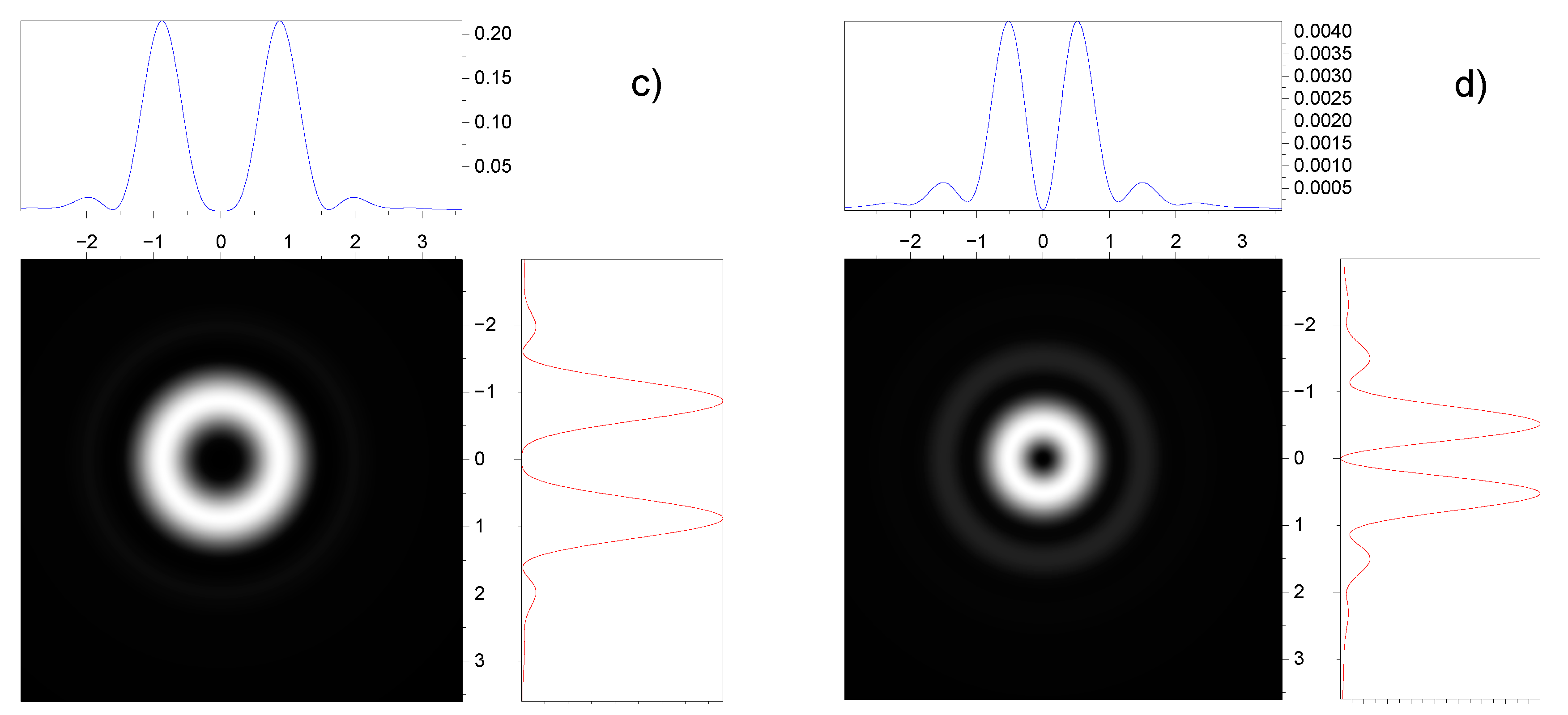
As can be seen, the intensity profiles of the transverse components are similar for topological charges with opposite signs (Figure 3a, 3c), but the longitudinal components differ significantly (Figure 3b, 3d). If for a positive topological charge l = 1 the longitudinal component has a ring shape (Figure 3b), then for a negative topological charge l = 1 it has a Gaussian shape (Figure 3d). This effect can be interpreted as an orbital Hall effect.
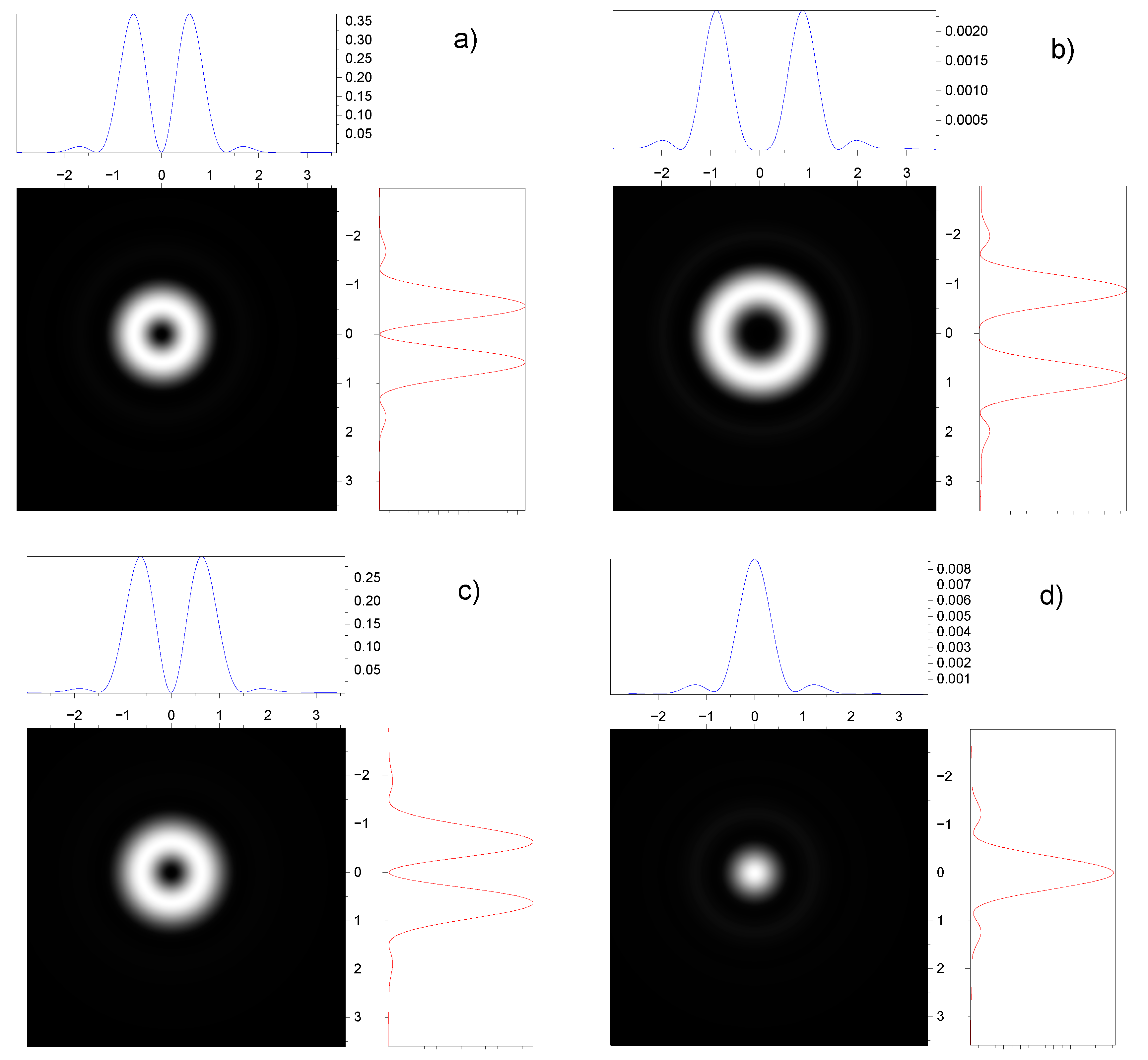
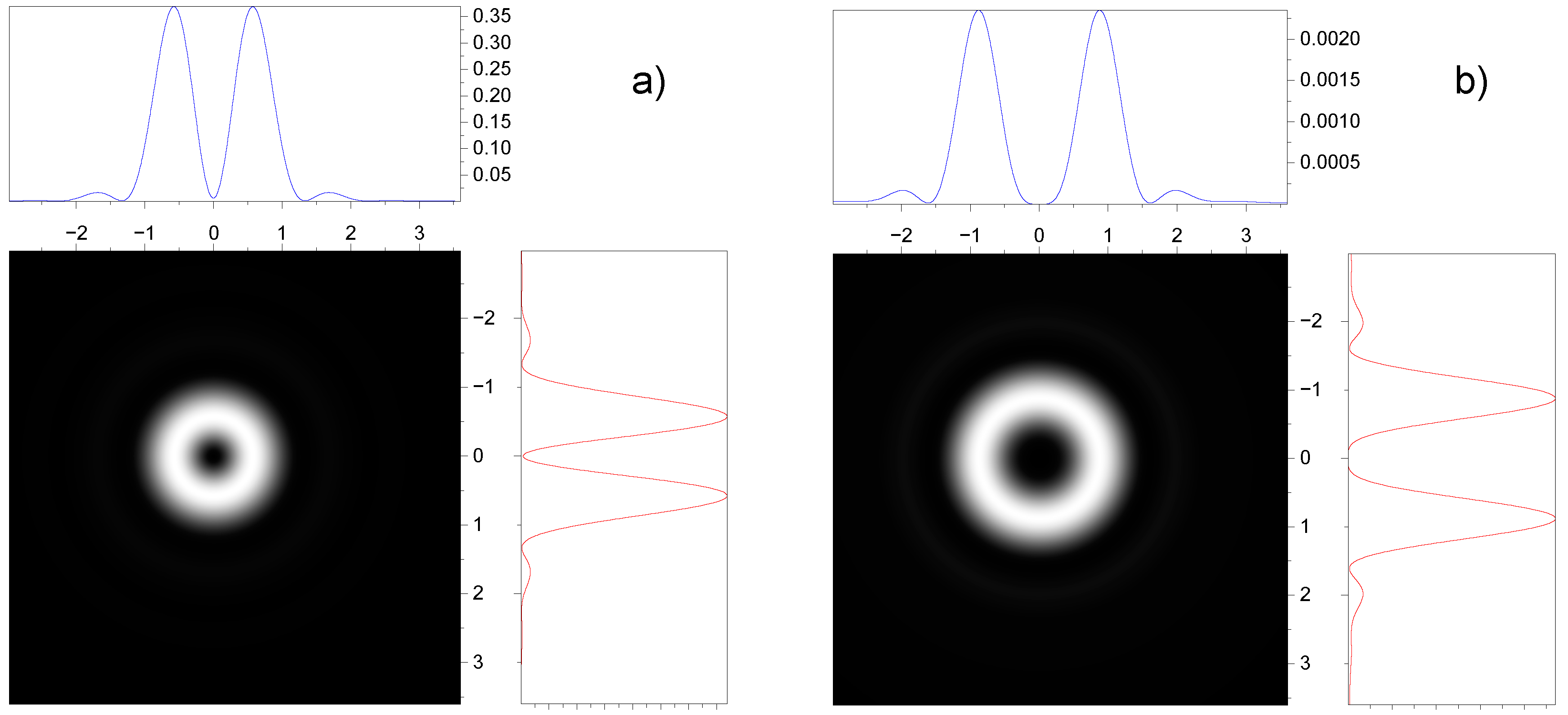
Figure 4 shows the intensity profiles of the transverse and longitudinal components of the field in the focal plane z f for circularly polarized incident beams with opposite helicity signs and similar azimuthal indices (topological charges). The intensity profiles of both the transverse and longitudinal components are like to the intensity profiles of incident beams with topological charges of opposite signs and the same circular polarization (Figure 3). This is because the spin-orbital interaction term l σ in the equations describing the evolution of an incident beam in a graded-index medium retains its sign and numerical value.
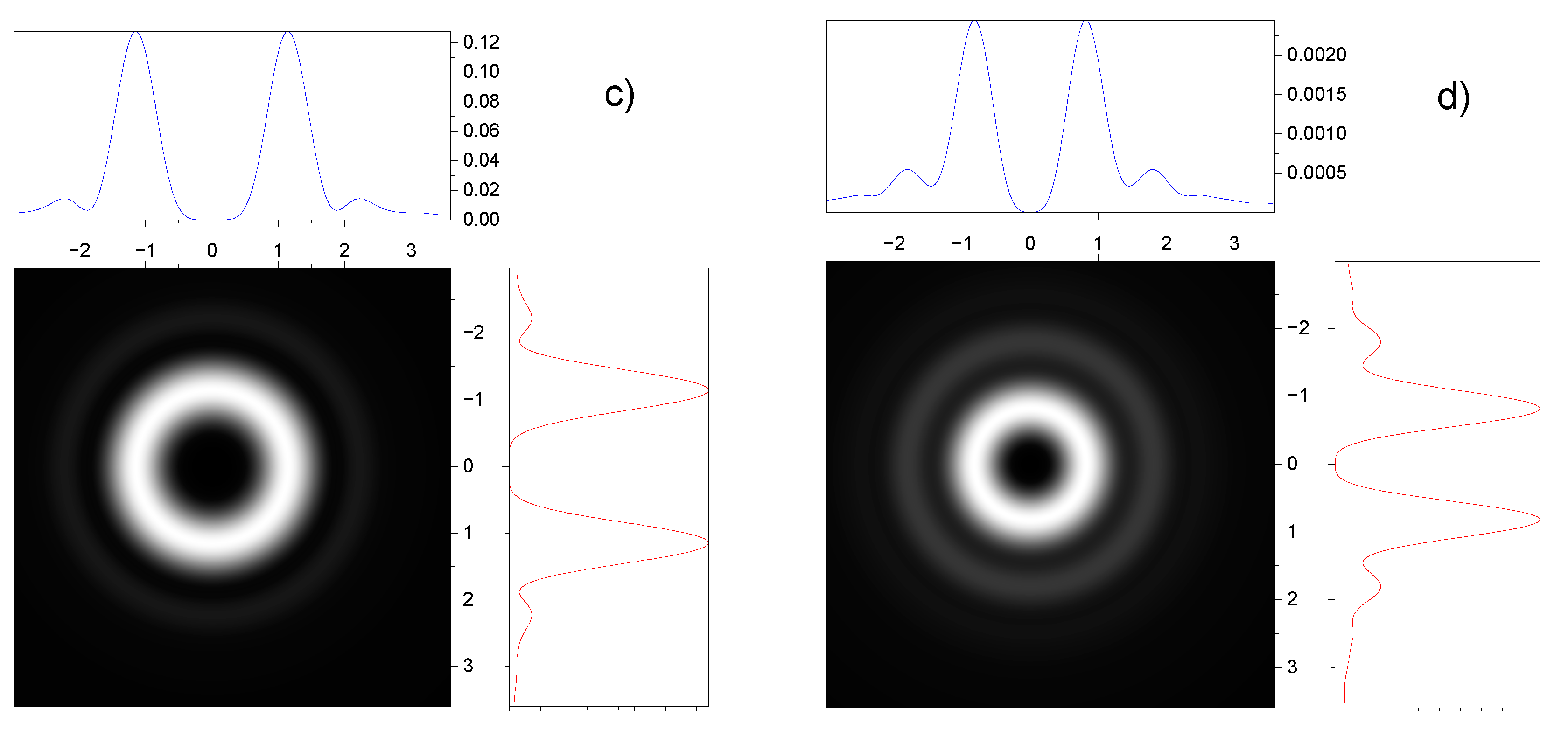
In Figure 5 the intensity profiles of the transverse and longitudinal field components in a focal plane z f are presented for the incident beams with the right- and left- handed polarizations and different topological charges. The total angular momentum of both incident beams j = l + σ = 1 and the radial index p = 0.
It is seen that the shapes of transverse field components are different. If for a right- handed polarization with σ = 1 the longitudinal component has a Gaussian shape (Figure 5a), then for a left- handed polarization with σ = 1 it has a ring shape (Figure 5c). There is a difference in the shapes of the transverse components, although the total angular momentum is the same in both cases.
In Figure 6 the intensity profiles of the transverse and longitudinal field components in a focal plane z f are presented for the incident beams with the right- and left- handed polarizations and different topological charges l = 1 and l = 3 . The total angular momentum of both incident beams j = l + σ = 2 and the radial index p = 0.
As can be seen the intensity distributions of the transverse and longitudinal field components for the right- and left- handed polarizations have the ring shapes. However, the radii of the rings for the transverse components differ significantly.
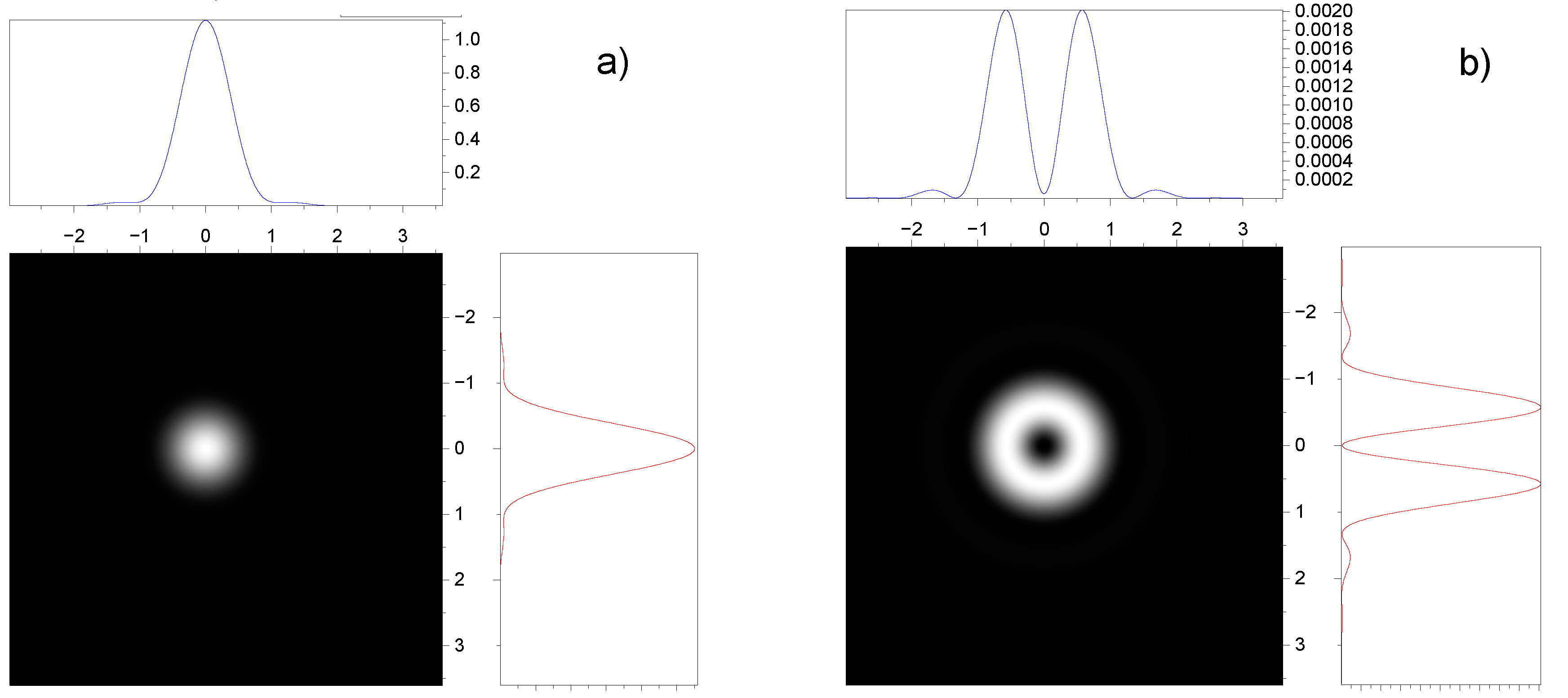
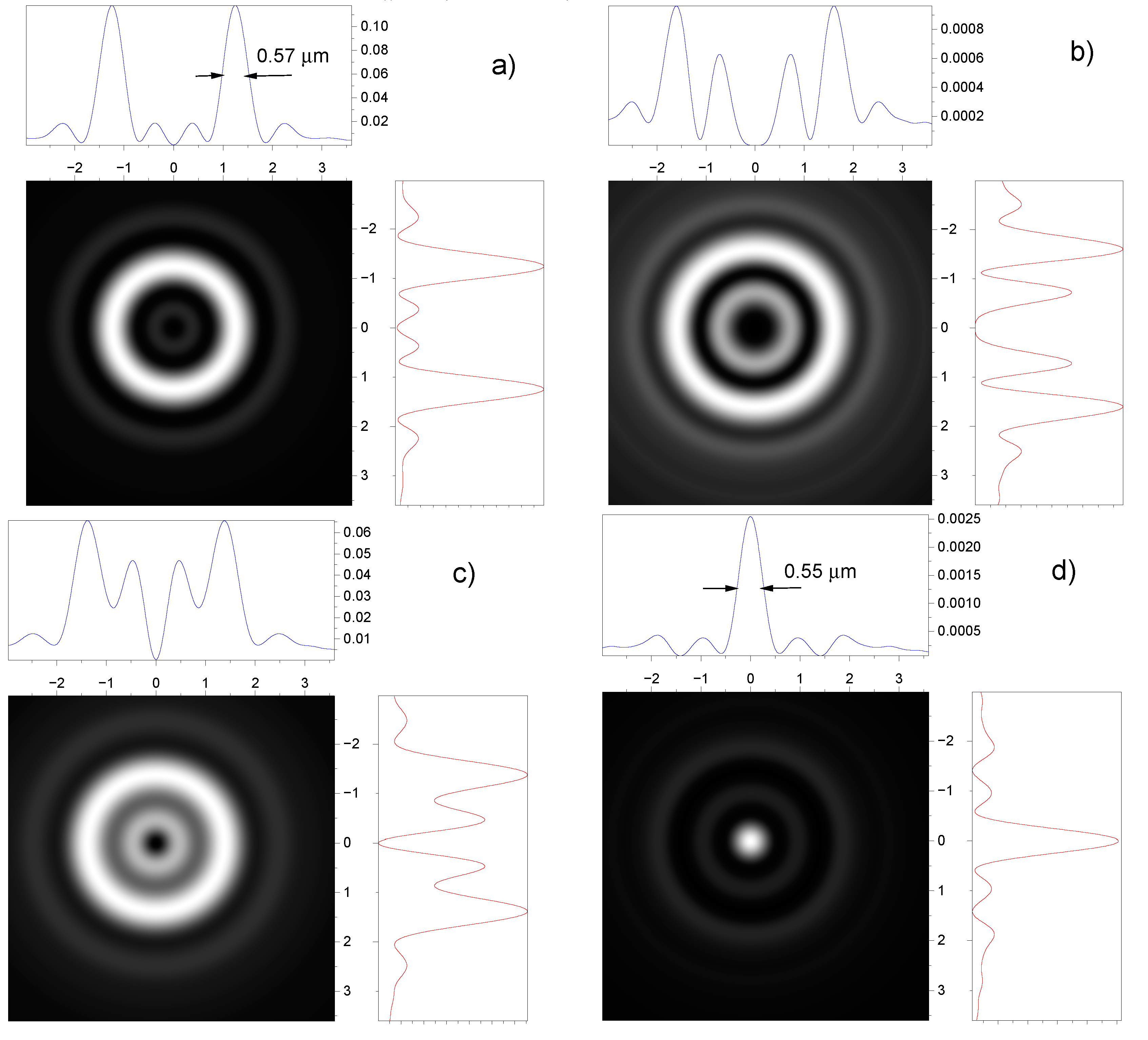
In Figure 7 the intensity profiles of the transverse and longitudinal field components in a focal plane z f are presented for the incident beams with the right- and left- handed polarizations, the radial index p = 1 and the same topological charges l = 1 .
It can be seen that the ring size in Figure 7a is much larger than the ring size in Figure 3a, although both cases have the same total angular momentum j = l + σ = 2 . The transverse components have an annular shape, whereas the longitudinal component of the left- handed polarization has a Gaussian shape (Figure 7d). Note that the spot size of the longitudinal field component in the plane of focus is less than the wavelength. The FWHM value (full width at half maximum) of the focused spot in the longitudinal component of the field is only 0.55 μm (Figure 7d). The thickness of the ring is also less than the wavelength (Figure 7 a).

3.3. Effect of spin-orbit interaction on the speed of vortex beams in optical fiber

Spin-orbit interaction affects the trajectory and intensity distribution of the light beam at propagation in a graded-index medium. The modes of a cylindrical waveguide are degenerated in the scalar approximation. When the vector term in the wave equation defining the spin-orbit interaction is considered, the spectrum of the propagation constant is split. The splitting of levels due to the term ∇ε (spin-orbit interaction of photons) in lens-like media has been considered in several papers [58,59]. Spin-orbit interaction in waveguides can significantly change the energy spectrum, causing splitting and removal of degeneracy of modes with different radial and azimuthal indices and polarizations [48,56,57]. These effects affect the group delay of modes in optical waveguides.
The group delay of the modes or the average time of arrival of a pulse are given by [48,57]
τ = z v g = z c β k z n 0 c + z n 0 c η 2 32 11 ν + 1 2 j 2 2 j σ ,
where c is the light velocity in vacuum, v g is the mode-group velocity, z is the length of the fiber, j = l + σ is the total angular momentum, σ is the spin angular momentum.
The group velocities v g = z / τ of vortex modes with right- and left- handed polarizations differ from each other, therefore, effective anisotropy is induced due to spin-orbit interaction. Such an asymmetry does not exist in the case of zero orbital momentum l = 0 . It follows from (10) that the group velocity of the modes decreases with increasing angular momentum of the propagating modes. Note that a similar result was obtained for a twisted light in vacuum in [60,61].
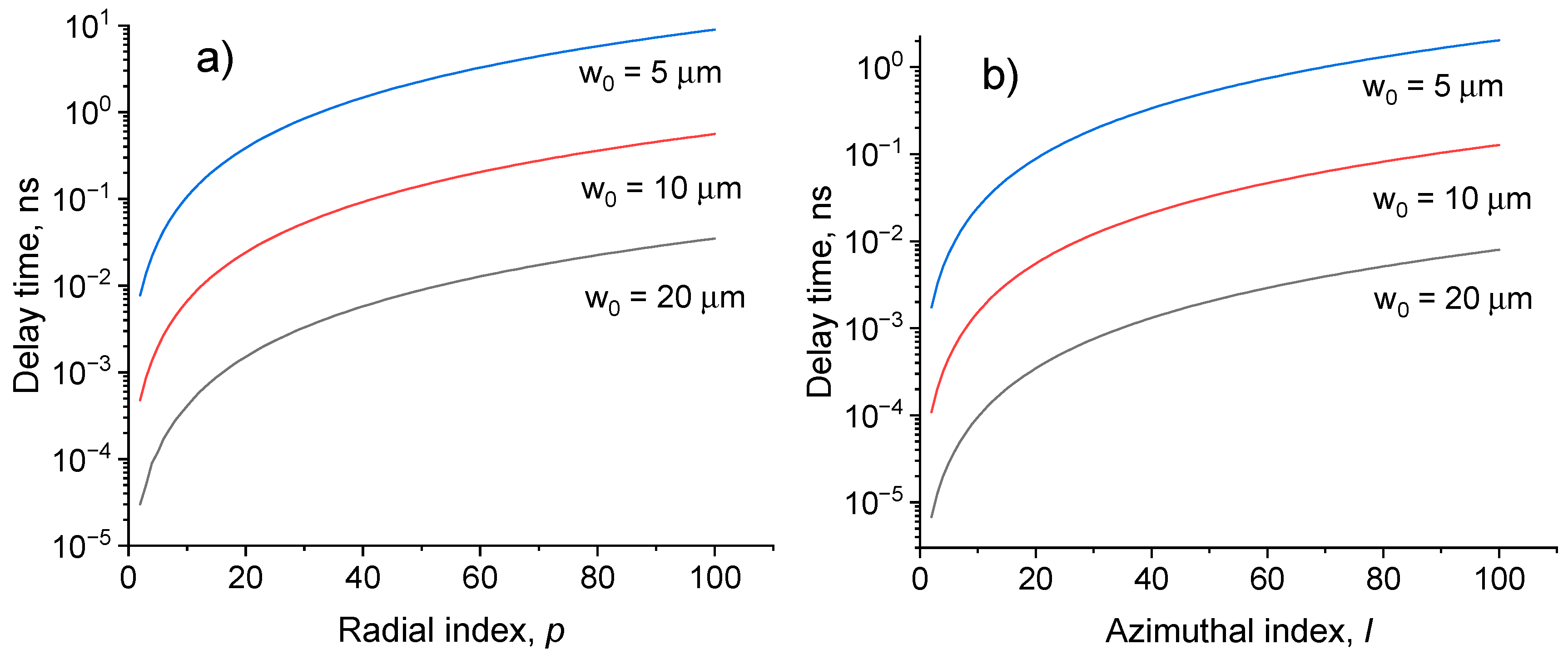
In Figure 8a the relative propagation delay of modes compared with the fundamental mode as a function of radial mode number p for various fundamental mode radiuses w 0 = 2 / k ω 1 / 2 is presented. In Figure 8b the delay times of the azimuthal modes of fixed radial indices l ( p = 0 ) are presented.
It can be seen that the delay time increases with increasing radial and azimuthal indices. The delay time also increases with a decrease in the radius of the fundamental mode w 0 .

Spin-induced asymmetry

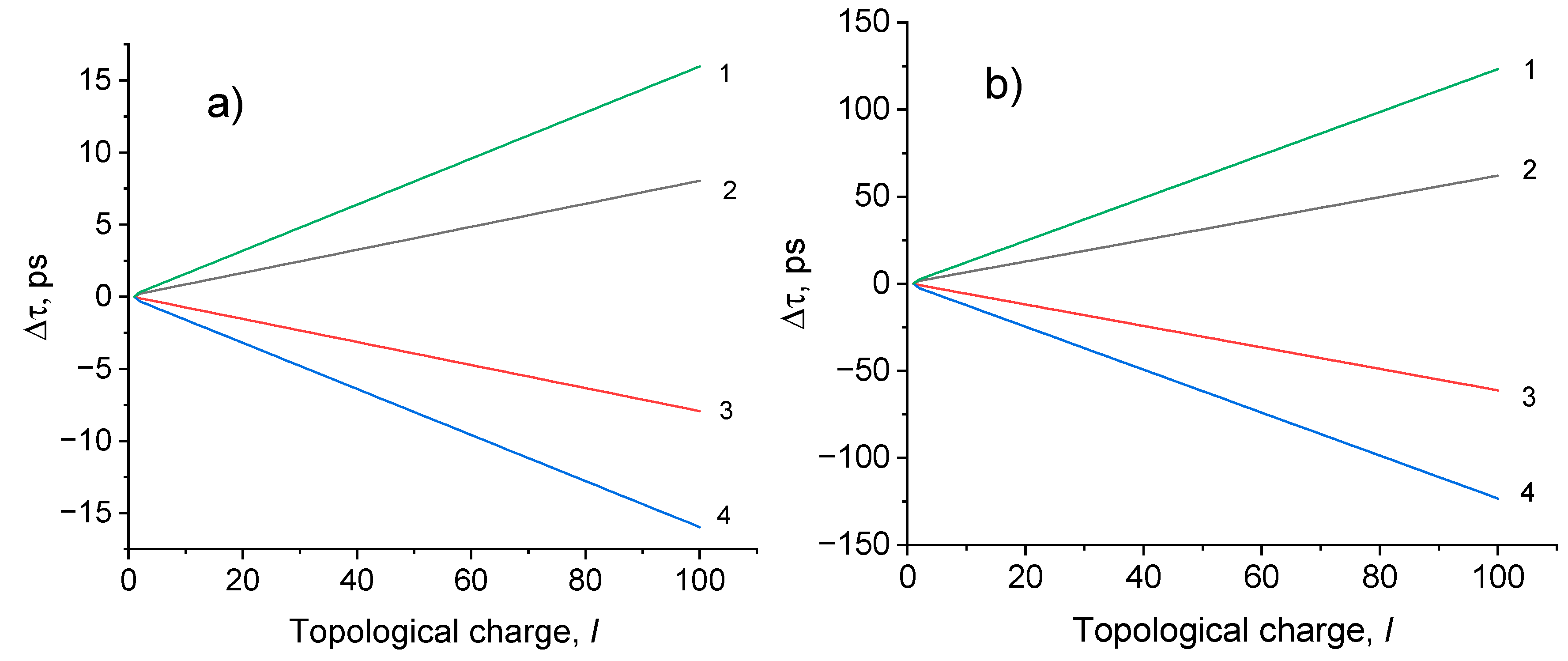
It follows from (10) that the group delay time depends on the spin angular momentum σ. Figure 9 shows the spin-dependent relative delay times ∆τ between pulses of different polarization states depending on the topological charge for waveguides with different gradient parameters.
It is seen from Figure 9, that in the case of positve azimuthal indices, the delay time of a pilse with left- handed polarization is longer than that of pulses with linear and right- handed polarizations, i.e. τ + 1 < τ 0 < τ 1 . This indicates that a right- handed polarized pulse propagates at a higher speed than linear and left- haded polarized pulses, i.e. v 1 < v 0 < v + 1 . In the case of negative azimuthal indices, the delay time of a pilse with right- handed polarization is longer than that of pulses with linear and left- handed polarizations, i.e. τ + 1 > τ 0 > τ 1 . This indicates that in this case a left- handed polarized pulse propagates at a higher speed than linear and right- handed polarized pulses, i.e. v 1 > v 0 > v + 1 .This effect can be attributed to the temporary spin Hall effect, which manifests itself as a difference in the arrival time of pulses with different circular polarization.
Thus, the pulses with right- and left- handed polarizations propagate with different velocities due to spin-orbit interaction. The spin-orbit interaction is responsible also for the degeneracy lifting of modes with distinct orbital angular momentum (OAM) and polarization but the same total angular momentum. The removal of degeneracy can be considered as an optical analogue of the Lamb shift, in which the levels are separated between degenerate states with the same total angular momentum. This level splitting is very small for ordinary optical fibers, where w 0 λ , but it becomes significant for fibers with a diameter of the order of the wavelength. Numerical estimates have shown that the elimination of degeneracy leads to a delay time between degenerate modes of the order of 1 ns/km for an optical fiber with a radius of the funfdamental mode of the order of the wavelength of light.

4. Conclusion

Thus, the effects of nonparaxiality and spin-orbit coupling on the axial and radial intensity distributions, and on the group velocities of modes are studied by solving the full three-component field Maxwell’s equations. It is shown that nonparaxiality causes an asymmetry in the distribution of the field intensity in the axial direction during tight focusing. Spin-orbit interaction induces the effective anisotropy in an isotropic graded-index medium causing asymmetry effects between the right- and left-handed polarized beams. Note that these effects can be regarded as a manifestation of the optical spin-Hall effect [28,29] which arises due to a spin-orbit coupling. In its turn, the spin-Hall effect is related to the geometric Berry phase [10,26,32,62]. It was shown in [10,32], that the spin Hall effect and the Berry phase are closely associated with the spin angular momentum dynamics and can be explained in terms of the Coriolis effect.
Future research may be related to the study of asymmetric effects in the propagation of vortex pulses and partially polarized and partially coherent vortex beams in a graded-index medium [63,64,65,66,67]. Of particular interest is the consideration of the effects of large-scale revival [39,68], the transverse spin phenomenon [69,70,71] and the optical spin Hall effect [72,73].
In summary, the modal solutions in a GRIN medium, which are the hybrid vector Laguerre-Gauss modes with spin-orbit entanglement, are used to study the propagation of vector wave beams in a graded-index medium. Modes exhibiting hybrid entanglement between spin and orbital angular momentum may be useful for classical implementations of quantum communication and computational tasks. The asymmetric distribution of the field intensity of the focused spot in the axial direction is shown. The asymmetry effects manifesting in different intensity distributions in the focal plane for opposite handedness of vorticity and/or polarization are demonstrated. It is shown that the group velocities of vortex modes with right- and left-handed polarizations differ from each other, so the effective anisotropy is induced due to spin-orbit interaction. The velocities of the left- and right- handed circularly polarized light pulses propagating in a graded-index fiber are different, which leads to a difference in the arrival time of pulses with opposite circular polarizations. This difference increases with the topological charge and radial index. The different delay times for opposite handedness of polarization can be considered as a temporal spin Hall effect, which can be observed for light with left- and right- handed circular polarization in an isotropic graded-index fiber. These effects influence on the group delay of modes and the average time of arrival of a pulse in optical fibers and become important in fiber optic communications with high carrying capacities and faster transmission rates.

Funding

This research was funded by the Ministry of Science and Higher Education of the Russian Federation under the State contract No. FFNS-2022-0009.

Data Availability Statement

Not applicable.

Conflicts of Interest

The author declareы no conflict of interest.

References

  1. Fedotov, V.A.; Mladyonov, P.I.; Prosvirnin, S.I.; Rogacheva, A.V.; Chen, Y.; and Zheludev, N.I. Asymmetric Propagation of Electromagnetic Waves through a Planar Chiral Structure. Phys. Rev. Lett. 2006, 97, 167401. [Google Scholar] [CrossRef]
  2. Xu, Y.; Shi, Q.; Zhu, Z.; and Shi, J. Mutual conversion and asymmetric transmission of linearly polarized light in bilayered chiral metamaterial. Opt. Expr. 2014, 22, 25679–25688. [Google Scholar] [CrossRef] [PubMed]
  3. Plum, R.; Lin, X.X.; Fedotov, V.; Chen, Y.; Tsai, D.P.; Zheludev, N.I. Metamaterials: Optical Activity without Chirality. Phys. Rev. Lett. 2009, 102, 113902. [Google Scholar] [CrossRef]
  4. Goos, F.; Hanchen, H. Ein neuer und fundamentaler versuch zur total reflexion. Ann. Phys. (Leipzig) 1947, 1, 333–345. [Google Scholar] [CrossRef]
  5. Imbert, C. Calculation and experimental proof of the transverse shift induced by total internal reflection of a circularly polarized light beam. Phys. Rev. D 1972, 5, 787–796. [Google Scholar] [CrossRef]
  6. Petrov, N.I. Reflection and transmission of strongly focused light beams at a dielectric interface. J. Mod. Opt. 2005, 52, 1545–1556. [Google Scholar] [CrossRef]
  7. Petrov, N.I. Frustrated-total-internal-reflection-based thin-film color separator. Opt. Lett. 2007, 32, 2744–2746. [Google Scholar] [CrossRef]
  8. Petrov, N.I. Splitting the bandwidth of a frustrated total internal reflection filter with nanoparticle inclusions. OSA Cont. 2020, 3, 2591–2601. [Google Scholar] [CrossRef]
  9. Gorodetsky, Y.; Niv, A.; Kleiner, V.; and Hasman, E. Observation of the Spin-Based Plasmonic Effect in Nanoscale Structures. Phys. Rev. Lett. 2008, 101, 043903. [Google Scholar] [CrossRef]
  10. Bliokh, K.Y.; Gorodetski, Y.; Kleiner, V.; and Hasman, E. Coriolis effect in optics: unified geometric phase and spin-Hall effect. Phys. Rev. Lett. 2008, 101, 030404. [Google Scholar] [CrossRef]
  11. Petrov, N.I.; Danilov, V.A.; Popov, V.V.; and Usievich, B.A. Large positive and negative Goos-Hänchen shifts near the surface plasmon resonance in subwavelength grating. Opt. Express 2020, 28, 7552–7564. [Google Scholar] [CrossRef]
  12. Petrov, N.I.; Sokolov, Y.M.; Stoiakin, V.V.; Danilov, V.A.; Popov, V.V.; Usievich, B.A. Observation of Giant Angular Goos-Hanchen Shifts Enhanced by Surface Plasmon Resonance in Subwavelength Grating. Photonics 2023, 10, 180. [Google Scholar] [CrossRef]
  13. Gorodetski, Y.; Shitrit, N.; Bretner, I.; Kleiner, V.; and Hasman, E. Observation of optical spin symmetry breaking in nanoapertures. Nano Letters 2009, 9, 3016–3019. [Google Scholar] [CrossRef]
  14. Vuong, L.T.; Adam, A.J.L.; Brok, J.M.; Planken, P.C.M.; and Urbach, H.P. Electromagnetic spin-orbit interactions via scattering of subwavelength apertures. Phys. Rev. Lett. 2010, 104, 083903. [Google Scholar] [CrossRef]
  15. Rytov, S.M. On transition from wave to geometrical optics. Dokl. Akad. Nauk USSR 1938, 18, 263–266. [Google Scholar]
  16. Vladimirsky, V.V. On rotation of polarization plane in twisted ray of light. Dokl. Akad. Nauk USSR 1941, 31, 222–225. [Google Scholar]
  17. Tomita, A.; Chiao, R.Y. Observation of Berry's Topological Phase by Use of an Optical Fiber. Phys. Rev. Lett. 1986, 57, 937–940. [Google Scholar] [CrossRef]
  18. Berry, M.V. Quantal phase factors accompanying adiabatic changes. Proc. R. Soc. Lond. A 1984, 392, 45–57. [Google Scholar]
  19. Zel’dovich, B.Ya. , and Kundikova, N.D. Intrafibre rotation of the plane of polarization. Quant. Electron. 1995, 25, 172–174. [Google Scholar] [CrossRef]
  20. Zel’dovich, B. Y.; Liberman, V. S. Rotation of the plane of a meridional beam in a graded-index waveguide due to the circular nature of the polarization. Sov. J. Quant. Electron. 1990, 20, 427–428. [Google Scholar] [CrossRef]
  21. Zel’dovich, B. Y.; Kitaevskaya, I.V.; Kundikova, I.D. Inhomogeneity of the optical Magnus effect. Quant. Electron. 1996, 26, 87–88. [Google Scholar] [CrossRef]
  22. Petrov, N.I. Depolarization of light in a graded-index isotropic medium. J. Mod. Opt. 1996, 43, 2239–2249. [Google Scholar] [CrossRef]
  23. Petrov, N.I. Evolution of polarization in an inhomogeneous isotropic medium. JETP 1997, 85, 1085–1093. [Google Scholar] [CrossRef]
  24. Petrov, N.I. Evolution of Berry's phase in a graded-index medium. Phys. Lett. A 1997, 234, 239–250. [Google Scholar] [CrossRef]
  25. Petrov, N.I. The influence of polarization on the trajectory and the width of a radiation beam in an inhomogeneous medium. Las. Phys. 2000, 10, 619–621. [Google Scholar]
  26. Bliokh, K.Y.; Niv, A.; Kleiner, V.; Hasman, E. Geometrodynamics of spinning light. Nat. Photon. 2008, 2, 748–753. [Google Scholar] [CrossRef]
  27. Liberman, V.S.; Zel’dovich, B.Y. Spin-orbit interaction of a photon in an inhomogeneous medium. Phys. Rev. A 1992, 46, 5199–5207. [Google Scholar] [CrossRef] [PubMed]
  28. Onoda, M.; Murakami, S.; Nagaosa, N. Hall Effect of Light. Phys. Rev. Lett. 2004, 93, 083901. [Google Scholar] [CrossRef]
  29. Kavokin, A.; Malpuech, G.; Glazov, M. Optical Spin Hall Effect. Phys. Rev. Lett. 2005, 95, 136601. [Google Scholar] [CrossRef]
  30. Snyder, A. W.; Love, J. D. Optical waveguide theory; Chapman and Hall: London, N.Y., 1983. [Google Scholar]
  31. Bliokh, K.Y.; Desyatnikov, A.S. Spin and orbital Hall effects for diffracting optical beams in gradient-index media. Phys. Rev. A 2009, 79, 011807. [Google Scholar] [CrossRef]
  32. Bliokh, K. Y. Geometrodynamics of polarized light: Berry phase and spin Hall effect in a gradient-index medium. J. Opt. A: Pure Appl. Opt. 2009, 11, 094009. [Google Scholar] [CrossRef]
  33. Dugin, A.; Zel’dovich, B.; Kundikova, N.; Liberman, V. Effect of circular polarization on the propagation of light through an optical fiber. J. Exp. Theor. Phys. Lett. 1991, 53, 197–199. [Google Scholar]
  34. Liberman, V.S.; Zel’dovich, B.Y. Spin-orbit interaction of a photon in an inhomogeneous medium. Phys. Rev. A 1992, 46, 5199–5207. [Google Scholar] [CrossRef]
  35. Bliokh, K.Y.; Ostrovskaya, E.A.; Alonso, M.A.; Rodriguez-Herrera, O.G.; Lara, D.; and Dainty, C. Spin-to-orbital angular momentum conversion in focusing, scattering, and imaging systems. Optics Express 2011, 19, 26132–26149. [Google Scholar] [CrossRef]
  36. Petrov, N.I. Spin-orbit and tensor interactions of light in inhomogeneous isotropic media. Phys. Rev. A 2013, 88, 023815. [Google Scholar] [CrossRef]
  37. Petrov, N.I. Spin-dependent transverse force on a vortex light beam in an inhomogeneous medium. JETP Letters 2016, 103, 443–448. [Google Scholar] [CrossRef]
  38. Zhao, R.; Deng, F.; Yu, W.; Huang, J.; and Deng, D. Propagation properties of Airy–Gaussian vortex beams through the gradient-index medium. J. Opt. Soc. Am. A 2016, 33, 1025–1031. [Google Scholar] [CrossRef]
  39. Petrov, N.I. Vector Laguerre–Gauss beams with polarization-orbital angular momentum entanglement in a graded-index medium. J. Opt. Soc. Am. A 2016, 33, 1363–1369. [Google Scholar] [CrossRef]
  40. Yin, X.; Hao, P.; Zhang, Y.; Zhao, Z.; Wu, J.; and Li, J. Propagation of noninteger cylindrical vector vortex beams in a gradient-index fiber. Opt. Lett. 2023, 48, 2484–2487. [Google Scholar] [CrossRef]
  41. Pei, S.; Xu, S.; Cui, F.; Pan, Q.; and Cao, Z. Propagation of a Bessel–Gaussian beam in a gradient-index medium. Appl. Opt. 2019, 58, 920–926. [Google Scholar] [CrossRef]
  42. Chakravarthy, T.P.; Viswanatham, N.K. Direct and reciprocal spin-orbit interaction effects in a graded-index medium. OSA Continuum 2019, 2, 1576–1589. [Google Scholar] [CrossRef]
  43. Sodha, M. S.; Ghatak, A. K. Inhomogeneous Optical Waveguides; Plenum Press: New York, NY, USA, 1977. [Google Scholar]
  44. Loffler, W.; van Exter, M. P.; Hooft, G. W.; Eliel, E. R.; Hermans, K.; Broer, D. J.; Woerdman, J. P. Polarization-dependent Goos–Hänchen shift at a graded dielectric interface. Opt. Commun. 2010, 283, 3367–3370. [Google Scholar] [CrossRef]
  45. Petrov, N.I. Beam shift in a graded-index optical fiber. J. Opt. 2013, 15, 014011. [Google Scholar] [CrossRef]
  46. Fock, V.A.; Leontovich, M.A. Solution of the Problem of Propagation of Electromagnetic Waves along the Earth’s Surface by Method of Parabolic Equations. Journal of Physics—USSR 1946, 10, 13–23. [Google Scholar]
  47. Petrov, N.I. Vector and tensor polarizations of light beams. Las. Phys. 2008, 18, 522–525. [Google Scholar] [CrossRef]
  48. Petrov, N.I. Splitting of levels in a cylindrical dielectric waveguide. Opt. Lett. 2013, 38, 2020–2022. [Google Scholar] [CrossRef]
  49. Eide, H.A.; and Stamnes, J.J. Exact and approximate solutions for focusing of two-dimensional waves. J. Opt. Soc. Am. A 1998, 15, 1285–1319. [Google Scholar]
  50. Petrov, N.I. Nonparaxial focusing of wave beams in a graded-index medium. Rus. J. Quant. Electron. 1999, 29, 249–255. [Google Scholar] [CrossRef]
  51. Petrov, N.I. Focusing of beams into subwavelength area in an inhomogeneous medium. Opt. Exp. 2001, 9, 658–673. [Google Scholar] [CrossRef]
  52. Yuan, Y.; Du, S.; Dong, Y.; Wang, F.; Zhao, C.; and Cai, Y. Nonparaxial propagation properties of a vector partially coherent dark hollow beam. JOSA A 2013, 30, 1358–1372. [Google Scholar] [CrossRef]
  53. Petrov, N.I. Macroscopic quantum effects for classical light. Phys. Rev. A 2014, 90, 043814. [Google Scholar] [CrossRef]
  54. Petrov, N.I. Nonparaxial Propagation of Bessel Correlated Vortex Beams in Free Space. Micromachines 2023, 14, 38. [Google Scholar] [CrossRef]
  55. Petrov, N.I. Nonparaxial Focusing of Partially Coherent Gaussian Schell-Model and Bessel-Correlated Beams in Free Space. Photonics 2023, 10, 857. [Google Scholar] [CrossRef]
  56. Bliokh, K.Yu.; Frolov, D.Yu. Spin-orbit interaction of photons and fine splitting of levels in ring dielectric resonator. Optics Commun. 2005, 250, 321–327. [Google Scholar] [CrossRef]
  57. Petrov, N.I. Depolarization of Light in Optical Fibers: Effects of Diffraction and Spin-Orbit Interaction. Fibers 2021, 9, 34. [Google Scholar] [CrossRef]
  58. Matsuhara, M. Analysis of electromagnetic-wave modes in lens-like media. JOSA 1973, 63, 135–138. [Google Scholar] [CrossRef]
  59. Thyagarajan, R.; and Chatak, A.K. Perturbation theory for studying the effect of the ∇ε term in lens-like media. Optics Commun. 1974, 11, 417–421. [Google Scholar] [CrossRef]
  60. Bouchard, F.; Harris, J.; Mand, H.; Boyd, R.W.; and Karimi, E. Observation of subluminal twisted light in vacuum. Optica 2016, 3, 351–354. [Google Scholar] [CrossRef]
  61. Petrov, N.I. Speed of structured light pulses in free space. Sci. Rep. 2019, 9, 18332. [Google Scholar] [CrossRef]
  62. Guo, Y.; Pu, M.; Zhang, F.; Xu, M.; Li, X.; Ma, X.; and Luo, X. Classical and generalized geometric phase in electromagnetic metasurfaces. Photonics Insights 2022, 1, R03. [Google Scholar] [CrossRef]
  63. Dong, M.; Bai, Y.; Yao, J.; Zhao, Q.; and Yang, Y. Propagation properties of partially coherent modified Bessel-Gauss beams through the gradient-index medium. Appl. Opt. 2020, 59, 8023–8028. [Google Scholar] [CrossRef]
  64. Wang, J.; Yang, M.; Guo, Z.; Feng, Z.; Li, J. Change in phase singularities of a partially coherent Gaussian vortex beam propagating in a GRIN fiber. Opt. Expr. 2020, 28, 4661–4673. [Google Scholar] [CrossRef]
  65. Wadood, S.A.; Liang, K.; Agrawal, G.P.; Visser, T.D.; Stroud, C.R.; Vamivakas, A.N. Propagation of Gaussian Schell-model beams in modulated graded-index media. Opt. Expr. 2021, 29, 21240–21251. [Google Scholar] [CrossRef]
  66. Dong, M.; Bai, Y.; Yao, J.; Zhao, Q.; and Yang, Y. Propagation properties of partially coherent modified Bessel–Gauss beams through the gradient-index medium. Appl. Opt. 2020, 59, 8023–8028. [Google Scholar] [CrossRef]
  67. Petrov, N.I. Sharp focusing of partially coherent Bessel-correlated beams by a graded-index lens. Opt. Lett. 2023, 48, 6048–6051. [Google Scholar] [CrossRef]
  68. Petrov, N.I. Remote focusing of a light beam. Las. Phys. Lett. 2016, 13, 015101. [Google Scholar] [CrossRef]
  69. Eismann, J.S.; Nicholls, L.H.; Roth, D.J.; et al. Transverse spinning of unpolarized light. Nat. Photonics 2021, 15, 156–161. [Google Scholar] [CrossRef]
  70. Ketara, M.L.; Kobayashi, H.; Brasselet, E. Sensitive vectorial optomechanical footprint of light in soft condensed matter. Nat. Photon. 2021, 15, 121–124. [Google Scholar] [CrossRef]
  71. Cardano, F.; Marrucci, L. Longitudinal fields and transverse rotations. Nat. Photonics 2021, 15, 1–3. [Google Scholar] [CrossRef]
  72. Qin, Z.; Zhang, L.; Zhang, R.; Zhang, P.; Qi, R.; Zhang, Q.; Ren, L.; and Jiang, L. Effect of the incident polarization on in-plane and out-of-plane spin splitting near the critical angle. Opt. Exp. 2023, 31, 853–863. [Google Scholar] [CrossRef]
  73. Lee, Y.U.; and Wu, J.W. Visualization of the optical spin Hall effect in out-of-plane refraction. Opt. Lett. 2023, 48, 5988–5991. [Google Scholar] [CrossRef] [PubMed]
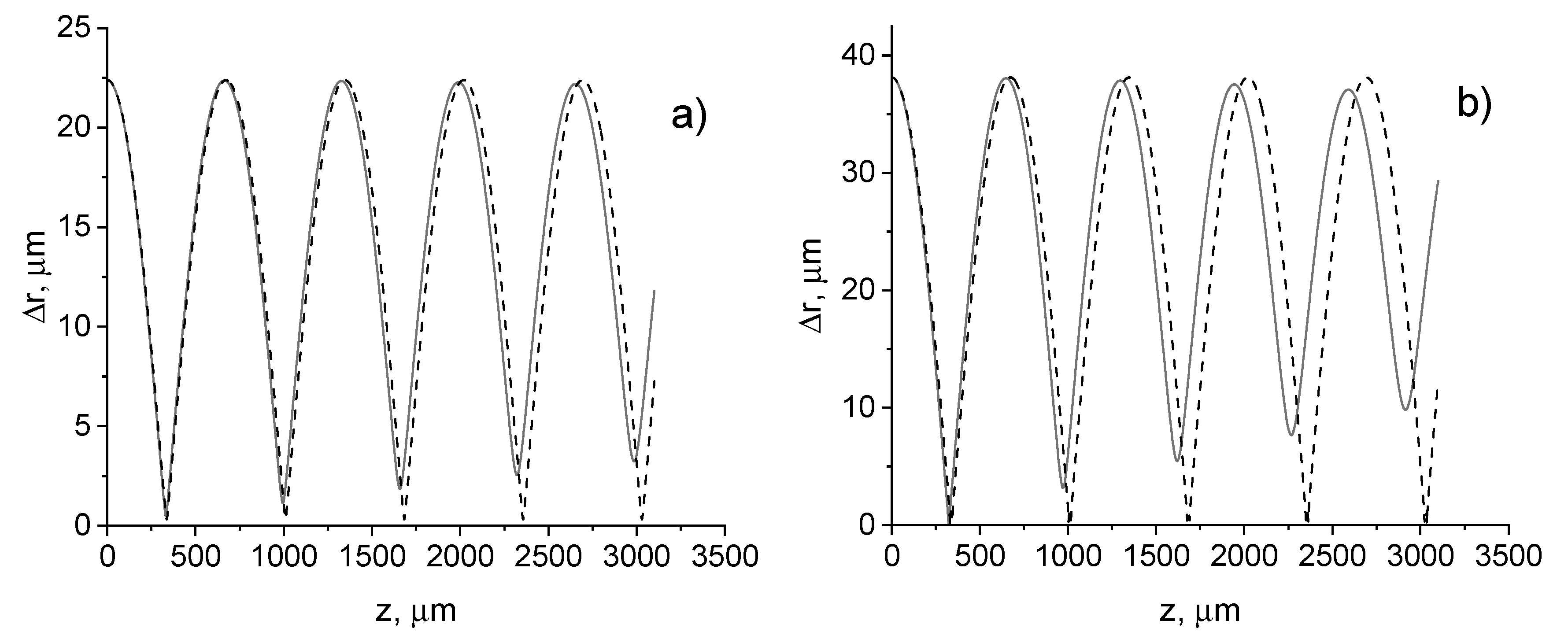
Figure 1. Beam width change with distance. l = 0, σ = 0, λ = 0.63   μ m , n 0 = 1.5 . Dashed line – paraxial approximation. (a) a 0 = 45 μm; (b) a 0 = 90 μm.
Preprints 92730 g001
Figure 2. Intensity profiles of the transverse electric field component in axial direction. l = 0, σ = 0, λ = 0.63   μ m , n 0 = 1.5 ,     a 0 = 45 μm. a nonparaxial; (b) – paraxial approximation; (c) – intensity profiles at a second focus plane: black line – nonparaxial, red line – paraxial; (d) – intensity profiles at a third focus plane: black line – nonparaxial, red line – paraxial.
Preprints 92730 g002
Figure 3. Intensity profiles of the transverse electric field component (left column) and the longitudinal electric field component (right column) for the circularly polarized incident beam with zero radial index in the focal plane z f = 331   μ m : (a, b) l = 1 ,   σ = 1 ; (c, d) l = 1 ,   σ = 1 .
Preprints 92730 g003
Figure 4. Intensity profiles of the transverse electric field component (left column) and the longitudinal electric field component (right column) for the circularly polarized incident beam with zero radial number in the focal planes z f = 331   μ m : (a, b) l = 1 ,   σ = 1 ; (c, d) l = 1 ,   σ = 1 .
Preprints 92730 g004
Figure 5. Intensity profiles of the transverse electric field component (left column) and the longitudinal electric field component (right column) for the circularly polarized incident beams with zero radial number in the focal planes z f = 331   μ m : (a, b) l = 0 ,   σ = 1 ; (c, d) l = 2 ,   σ = 1 .
Preprints 92730 g005aPreprints 92730 g005b
Figure 6. Intensity profiles of the transverse electric field component (left column) and the longitudinal electric field component (right column) for the circularly polarized incident beams with zero radial number in the focal planes z f = 331   μ m : (a, b) l = 1 ,   σ = 1 ; (c, d) l = 3 ,   σ = 1 .
Preprints 92730 g006aPreprints 92730 g006b
Figure 7. Intensity profiles of the transverse electric field component (left column) and the longitudinal electric field component (right column) for the circularly polarized incident beams with nonzero radial number p = 1 in the focal plane z f = 331   μ m : (a, b) l = 1 , σ = 1 ; (c, d) l = 1 ,   σ = 1 .
Preprints 92730 g007
Figure 8. Delay times as a function of radial (a) and azimuthal (b) indices, accordingly, z = 1 km, n 0 = 1.5 , σ = 0.
Preprints 92730 g008
Figure 9. Relative delay times as a function of topological charge: z = 1 km, n 0 = 1.5 ; 1 - delay between beams with σ = -1 and σ = 1 τ = τ 1 τ 1 ; 2 - τ = τ 0 τ 1 ; 3 - τ = τ 0 τ 1 ; 4 - τ = τ 1 τ 1 . (a) ω = 8 10 3 μm-1, (b) ω = 2.2 10 2 μm-1. Subindex in τ σ corresponds to the spin angular momentum σ = 0, 1, −1.
Preprints 92730 g009
Disclaimer/Publisher’s Note: The statements, opinions and data contained in all publications are solely those of the individual author(s) and contributor(s) and not of MDPI and/or the editor(s). MDPI and/or the editor(s) disclaim responsibility for any injury to people or property resulting from any ideas, methods, instructions or products referred to in the content.
Copyright: This open access article is published under a Creative Commons CC BY 4.0 license, which permit the free download, distribution, and reuse, provided that the author and preprint are cited in any reuse.
Prerpints.org logo

Preprints.org is a free preprint server supported by MDPI in Basel, Switzerland.

Subscribe

© 2024 MDPI (Basel, Switzerland) unless otherwise stated