Submitted:
07 December 2023
Posted:
08 December 2023
You are already at the latest version
Abstract
In this paper, experimental results about the performance of a Takagi-Sugeno Fuzzy Controller (TSFC) for an EV3 Ballbot Robotic System (EV3BRS) are reported. The physical configuration for the EV3BRS has the form of an inverted pendulum mounted on a ball. The EV3BRS is an underactuated robotic system with four outputs and two control torques. The Takagi-Sugeno Fuzzy Model (TSFM) design comes from linearization of the nonlinear model around two operation points near from the upright position of the EV3BRS's body. The Parallel Distributed Compensation (PDC) approach is used to the design of the TSFC. The Linear Matrix Inequalities (LMIs) approach is used to get the feedback gains for every local linear controller guaranteeing global asymptotically stability, via a more relaxed stability condition, of the overall fuzzy control system. Measurement and control data from and to the EV3BRS are transferred via telecontrol and telemetry.
Keywords:
ballbot
; linear matrix inequalities
; parallel distributed compensation
; Takagi-Sugeno fuzzy control
; Takagi-Sugeno fuzzy model
; telecontrol
; telemetry
; underactuated systems
1. Introduction
A ballbot is an omnidirectional underactuated robotic system driven through a spherical wheel and whose dynamics are based on the spherical inverted pendulum system [1,2]. The NXT Ballbot Robotic System (NXTBRS) is a small version from a huge robotic platform introduced in [2] but built using the robotics LEGO Mindstorms NXT kit plus two gyro sensors [3]. Due to the benefit that this robotics kit is reconfigurable and reprogrammable, besides its low–cost, it has been used in education and research activities [4]. The robotics kit comprises Direct Current (DC) motors with encoders, sensors, and the NXT brick as well as structural elements like wheels, gears, bars and balls [5]. The principal parts of the NXTBRS are two rubber tires attached to servomotors, one spherical wheel, two gyro sensors, and the NXT brick (See Figure 1).
Because some DC motor parameters can not be accurately measured, namely, moment of inertia and friction coefficient, the main control problem for a ballbot is the balancing of its body for the upright position at all time due to the uncertainties when considering the actuator dynamics. Some authors have used different values for the physical parameters of the servomotors based on experimental tests [3,5,6,7,8]. In [3], a type–1 servo system [9], also known as integral control structure [10], was employed to the control of a NXTBRS where feedback gains were calculated through the Linear Quadratic Regulator (LQR) design approach. The performance of the servo system was validated via simulation and experimental results. In [5], a LQR was designed to control a NXTBRS whose performance was also validated through numerical simulation and experiments. In [1], a robust controller was designed under the focus of Polytopic Linear Differential Inclusion (PLDI) models and Linear Matrix Inequalities (LMIs). A Polytopic Model (PM) for the NXTBRS was proposed where the gains for a LQR were designed via LMIs technique. In such a work, the parameters corresponding to both moment of inertia and friction coefficient from the NXT servomotors were taken from [3,5,6,7], and [8]. So, the NXTBRS PM was constituted by four linear subsystems, the so–called vertices, in such a way that all possible minimum and maximum values for the parameters from the NXT servomotors may be considered in the same PM. The Polytopic Controller (PC) (control law) was then given by state feedback plus an integral action, namely, in the form of a type–1 servo system via LQR design approach. Simulation and experimental results validated the performance of the PC in contrast with those from the classical LQRs tuned for each vertex from the PM, showing that for some vertices the classical LQR was not able to balance the NXTBRS; i.e. the PC was robust for the widespread range of parameters from the servomotors. In [11], Discrete-Time LQRs (DTLQRs) were designed to the control of a NXT ballbot when considering the physical parameters from each one of the systems given in [3,5,6,7,8]. Numerical simulation results validated the performance of the DTLQRs when comparing their response versus that from their respective continuous-time versions. In [12], an extended Kalman filter was used to estimate, under position measurements, the state vector of the NXTBRS. The estimated state vector is used by a LQR achieving the control objective. In that work has been shown that the closed–loop system is locally asymptotically stable. The viability of such proposal was validated via numerical simulation. In [13], a dual Takagi–Sugeno Fuzzy Controller (TSFC) was proposed to the control of a Ball Robot System (BRS) to operate in an independently way without coupling. The fuzzy model for the BRS is comprised of two fuzzy rules whose local linear models were obtained from linearizing the nonlinear model around from zero and five degrees with respect to the vertical unstable equilibrium position. Membership functions of the Gaussian–type were used. The BRS has the physical configuration of an inverted pendulum but supported by a bowling ball and driven through two 24V DC motors orthogonally placed. The BRS is about 40 cm height and 17 kg of weight. Simulation and experimental results validated the proposal. In [14], from the dynamic model for a ballbot given in terms of the Euler-Lagrange equations, a H-infinity (nonlinear optimal) controller was designed whose performance is evaluated via simulation results. The nonlinear model is linearized around a temporary operating point which is updated at each time-step of the control algorithm. Feedback control gains are computed through the solution of an algebraic Riccati equation solved at each time-step. Closed-loop stability is shown via Lyapunov approach.
Mobile robots have been playing a key role in the areas related with transportation, logistics and healthcare. Single-wheel robots, two-wheel robots, and omnidirectional-wheel (ODW) robots have been designed in order to gain an increase in mobility. A ball segway (BS), a ballbot-type mobile robot, was introduced in [15], where a PID two-loop controller is proposed to control ODWs for both balancing and transferring of the BS whose performance was evaluated experimentally. In [16], a double–loop controller is proposed to control the BS and whose performance was validated via simulation and experimental results. This BS has the capability to transport a single human passenger. It was shown that this BS can maintain its balance, perform trajectory tracking and rotate around its own vertical axis. The double-loop controller comprises a LQR outer-loop controller and a PI-plus-feedforward inner loop controller. A PD controller was added to control the rotation of the BS around its vertical axis. The driving mechanism for the BS consists of three ODWs. Its governing equations are given by a second order multi-input multi-output (MIMO) system with five degree-of-freedom (DOF). The system dynamics can be decoupled into three planar planes under certain conditions. So, the whole system can be operated by separately control on these decoupled dynamics. Robust controllers must be designed to face modeling uncertainties due to backlash between mechanical components, location center of mass, mass moment of inertia, nonlinearities from the motors, and friction between the ball and the road surface. In [17,18,19,20], a hierarchical sliding mode control (HSMC) approach was used to address the balancing and movement problem for the BS. In [21], an adaptive version of the HSMC approach to the control of the BS was proposed. A passivity-based nonlinear controller for a BS was suggested in [22]. In [23], a control scheme based on radial basis function networks jointly with the dynamic surface control approach for balancing and trajectory tracking of a BS was addressed. Control schemes based on partial feedback linearization approach and energy-based method were reported in [24,25,26]. The performance of the control schemes proposed in [18,21,23,26] was validated through numerical simulation whereas experimental results were exhibited in [19,22], and both simulation and experimental results were included in [17,20,24,25].
In this work, a TSFC is implemented on an EV3 Ballbot Robotic System (EV3BRS) in order to evaluate its performance in real-time for this kind of easy-to-build lightweight and low-cost prototype. It must be highlighted that the EV3BRS comprises an EV3 brick, this latter a more recent version from the NXT brick but with better capabilities. In our work, the Takagi-Sugeno Fuzzy Model (TSFM) is comprised of two fuzzy rules where the absolute value for the angular displacement of the EV3BRS’s body is considered as premise variable and whose membership functions differ from that of the Gaussian-type. Also, the TSFM is composed by two local linear models; the first one designed from a more far angle with respect to the vertical unstable equilibrium position of the EV3BRS’s body while the second one is designed from the zero degrees reference for the upright position. Moreover, the dynamics of the actuators is taken into account when linearizing the nonlinear model. Besides, a more relaxed stability condition to the design of the gains for the TSFC is used.
The manuscript is organized as follows. In Section 2 are described the nonlinear dynamic model and the state-variable equations of the EV3BRS including the dynamics of the actuator. The TSFM of the EV3BRS and the design procedure of the TSFC are included in Section 3. In Section 4, the experimental results about the performance of the TSFC in real-time are shown. In Section 5, the conclusion is drawn.
2. Dynamical model
In our work, a four degree–of–freedom (DOF) underactuated system consisting of a rigid body balancing atop a ball (See Figure 2) having two control inputs (See Figure 1), here known as ballbot EV3, is considered. When assuming that the whole dynamics of motion can be decomposed into two planes of motion, a Takagi-Sugeno fuzzy controller is designed from just taking one of that planes of motion as reference and then implemented in a decentralized way on each one. In this work, the controller design is carried out under the premise that there is no slipping between wheel and surface and that just viscous friction exists between wheel and body. The control inputs are just considered as torques. The generalized coordinates are given by the angular displacement of the ballbot’s body, namely , and the angle of the motor shaft, namely (See Figure 2).
Let us consider the model for the EV3BRS [3] given in the second–order matrix form [27]
whose form frequently is used to model the dynamics from robot arms of n DOF [28,29,30], where
with , , and which is referred as inertia (mass) matrix, symmetric and positive definite for all ,
is the centrifugal and Coriolis forces (damping) matrix,
is the gravitational forces or torques vector,
is the viscous friction forces vector, which depends on the joint velocities, and
is the vector of external forces corresponding to the torque exerted by the actuator. By inverse relationship, the dynamics of motion (1) may also be expressed in terms of the joint accelerations, i.e.,
with
where, if the existence of (8) is guaranteed, (7) is then given by
2.1. DC motor dynamics
The governing equations for the DC motor are are given by [27]
where is the armature inductance, is the direct armature current, v is the input armature voltage, is the armature resistance, and is the back electromotive force (BEMF) coming from the armature. Assuming , thus .
The DC motor torque is given by
i.e., the input torque is a voltage scaled by , with the torque constant of the motor [28].
Physical and electrical parametric values corresponding to the platform based on the LEGO Mindstorms EV3 kit are given in Table 1.
2.2. EV3BRS’s state–variable equations
From (9), by selecting the state variables as , , , and , the state–variable equations are then formed as
which can also be written as
3. Takagi–Sugeno Fuzzy Modelling
3.1. EV3BRS’s TSFM
The TSFM [31,32] is described by fuzzy IF–THEN rules, each one associated with a local linear system getting from the linearization around on an operation point for a nonlinear system [33,34,35]. From the fuzzy blending of the linear system models raises the overall fuzzy model of the system. The structure of a TSFM in continuous–time adopts the form:
Plant rule i:
where are measurable premise variables, are fuzzy sets, is the state vector, is the output vector, is the input vector, , , and r is for the number of fuzzy rules.
So, the overall output of the T–S fuzzy system (14) and (15) is inferred using a singleton fuzzifier, a center average defuzzifier and a product inference engine, from the pair of , as follows [36]:
where and , with the grade of membership of in , and
is the normalized weight of each IF–THEN rule.
In our work, the nonlinear model (13) is linearized around operation points and . Thus, taking , and recalling that from small–angle linearization and , the linear model has the form
where , , and .
From the parametric values in Table 1, (19) takes the form
which corresponds to the local linear system .
Hence, taking thus
with . Then, from (13), the corresponding linear model to this latter value for the operation point results
with , and .
3.2. Parallel Distributed Compensation (PDC)
The PDC technique [37] is used to design the fuzzy controller for the fuzzy model (14) and (15), where each rule is designed from the respective rule of the TSFM [33,34,35]. From the premise variables, the fuzzy controller shares the same fuzzy sets with the fuzzy model. So, the following fuzzy controller is inferred:
Control rule i:
where is the feedback gain. Thus, the entire fuzzy controller is given as
It should be noticed that the controller (25) is nonlinear.
3.3. TSFC Design
The solution to the controller fuzzy design problem consists into determine feedback gains for the linear controllers fulfilling the following theorem.
Theorem 1
Proof.
See [38]. □
The conditions (26) and (27) are not jointly convex in and . So, defining and such that for then , the stable fuzzy controller design problem is established as follows [38]:
Stable Fuzzy Controller Design Problem. Find and satisfying
The conditions (28) and (29) are LMIs with respect to variables X and . A positive definite matrix X and can be found satisfying such inequalities. From the solutions (28) and (29), a common positive definite matrix and feedback gains can be obtained as
Hence, assuming that the pair is controllable one proceeds with the stable fuzzy controller design. Then, solving the design problem through the use of the LMI Control Toolbox from MATLAB® the existence of a common positive definite matrix has been verified [39] for which feedback gains result as
4. Results
The following results were obtained from a real-time testing prototype using an EV3 brick, including the LEGO Mindstorms Kit, a tp-link wireless router WR840N, and a WiFi USB NetGear WNA1100. So, measurement and control data from and to the EV3BRS are transferred via telecontrol and telemetry. The EV3BRS prototype is shown in Figure 5. The proposed control scheme is programmed in Matlab/Simulink® (Matlab and Simulink are registered trademarks of MathWorks). Figure 6 shows the schematic representation of the experimental setup and the measurement/control signal route. Figure 7, Figure 8, Figure 9, Figure 10, Figure 11 and Figure 12 show the performance in real-time of the TSFC on the EV3BRS for initial conditions starting from zero, i.e., for the case for which the EV3BRS’s body is released from its the upright position. From Figure 7Figure 8, it can be seen that the EV3BRS’s body is maintained near to zero, i.e. near to its upright position, showing a better balance around its y-axis in contrast with that from the x-axis. Figure 9 and Figure 10 show the dynamics from each one of the actuators on its own rotor shaft. The control signal from each actuator is shown through Figure 8 and Figure 12 from which it can be seen that the actuator aligned with the y-axis exerts a minor effort. Also, it can be seen that the EV3BRS’s body and control effort tends to zero. It must be noticed that in our work we are focused into maintain the EV3BRS’s body at its upright position neglecting the angular displacement from the motor shaft (wheel). So, from experimental results it can be noticed that the control objective is successfully achieved in spite of faults that may be due to delays between communication signals. A video is attached to this draft version of the manuscript.
5. Conclusion
From the experimental evaluation results, we concluded that our proposal to the control of an EV3BRS performs well. So, it can be seen that the control objective has been reached just considering two fuzzy rules for the TSFM with membership functions differing from that of the Gaussian-type and taking the absolute value for the angular displacement of the EV3BRS’s body as premise variable for the fuzzy rules. Also, we confirm that when following the design control in a decentralized way, the control task can be carried out successfully although for one of the planes of motion the dynamics are more demanding. Moreover, as a disadvantage from the TSFC technique is the lack of the approach on the improvement of the transient dynamics when trying to reach the stability in fixed time. Furthermore, global asymptotically stability is achieved via a more relaxed stability condition. As future work, we will explore another design methodologies in order to evaluate their respective performance in the achievement of the control task in real–time.
Author Contributions
Conceptualization, F.J.; investigation, R.E., F.J. and J.V-T.; methodology, R.E. and F.J.; formal analysis, R.E.; validation, R.E., F.J. and J.V-T.; software, R.E.; data curation, R.E.; visualization, R.E., F.J. and J.V-T.; writing–original draft preparation, R.E. and F.J.; writing–review and editing, F.J.; supervision, F.J. and J.V-T.; funding acquisition, F.J.; resources, F.J.; project administration, F.J. All authors have read and agreed to the published version of the manuscript.
Funding
This research was funded by Tecnológico Nacional de México (TecNM) through project 18437.23-P and, partially, under grant 39873 from EDD 2022 program. This work was supported by CONACYT, México, under grant 759631.
Conflicts of Interest
The authors declare no conflict of interest.
Abbreviations
The following abbreviations are used in this manuscript:
| BEMF | Back Electromotive Force |
| BRS | Ball Robot System |
| BS | Ball Segway |
| DC | Direct Current |
| DOF | Degree-of-Freedom |
| DTLQR | Discrete-Time Linear Quadratic Regulator |
| EV3BRS | EV3 Ballbot Robotic System |
| HSMC | Hierarchical Sliding Mode Control |
| LQR | Linear Quadratic Regulator |
| LMIs | Linear Matrix Inequalities |
| MIMO | Multi-Input Multi-Output |
| NXTBRS | NXT Ballbot Robotic System |
| ODW | Omnidirectional Wheel |
| PDC | Parallel Distributed Compensation |
| PLDI | Polytopic Linear Differential Inclusion |
| PC | Polytopic Controller |
| PM | Polytopic Model |
| TSFC | Takagi-Sugeno Fuzzy Controller |
| TSFM | Takagi-Sugeno Fuzzy Model |
References
- García, R.; Arias, M. Linear Controllers for the NXT Ballbot with Parameter Variations Using Linear Matrix Inequalities. Control Syst. Mag. 2016. [Google Scholar]
- R. Hollis, Ballbots, Sci. Am., vol. 295, no. 4, 2006.
- Yamamoto, Y. NXT Ballbot Model–Based Design–Control of Self–balancing Robot on a Ball, Built with LEGO Mindstorm NXT, 1st ed., Cybernet Systems, Japan, 2009.
- Gawthrop, P.; McGookin, E. `A LEGO–based control experiment. Control Syst. Mag. 2004, 24. [Google Scholar]
- Sánchez, P.; Arribas, T.; Gómez, M.; Rodríguez, O. A Monoball Robot Based on LEGO Mindstorms. Control Syst. Mag. 2012. [Google Scholar]
- P. Hurbain, LEGO 9V Technic Motors compared characteristics. [Online]. Available: http://www.philohome.com/motors/motorcomp.
- Pinto, M.; Bermúdez, G. Parameters determination of a mobil robot of LEGO Mindstorms (in Spanish). Ingeniería Investigación y Desarrollo 2007, 5, 7–13. [Google Scholar]
- R. García, Development of a robot ballbot–like for control applications (in Spanish). [Online]. Available: http://jupiter.utm.mx/tesis_dig/12495.pdf.
- Ogata, K. Modern Control Engineering. Fourth Edition. Upper Saddle River, NJ: Prentice Hall, 2002.
- Franklin, G.F.; Powell, J.D.; Emami–Naeini, A. Feedback Control of Dynamic Systems. Sixth Edition. Upper Saddle River, NJ: Pearson, 2010.
- I. Ortíz, F. I. Ortíz, F. Jurado, and E.J. Ollervides-Vázquez, Discrete-Time Linear Quadratic Regulator for a NXT Ballbot System, 2022 Int. Conf. on Mechatronics, Electronics and Automotive Eng. (ICMEAE), Cuernavaca, Morelos, México, pp. 95-100, 2022.
- L.E. Herrera, R. L.E. Herrera, R. Hernández, and F. Jurado, Control and extended Kalman filter based estimation for a ballbot robotic system, XX Congreso Mexicano de Robótica (COMRob), Ensenada, Baja California, México, 2018.
- Chiu, C.H.; Peng, Y.F. Design of Takagi-Sugeno Fuzzy Control Scheme for Real World System Control. Sustainability 2019, 11, 3855. [Google Scholar] [CrossRef]
- G. Rigatos, M. G. Rigatos, M. Abbaszadeh, J. Pomares, A nonlinear optimal control method for the ballbot autonomous vehicle, 2020 American Control Conf., Denver, CO, USA, pp. 665-670, 2020.
- D.B. Pham, S.G. D.B. Pham, S.G. Lee, S. Back, J.J. Kim, M.K. Lee, Balancing and translation control of a ball Segway that a human can ride, 2016 16th Int. Conf. on Control, Automation and Systems (ICCAS), Gyeongju, Korea (South), 2016.
- Pham, D.B.; Kim, H.; Kim, J.J.; Lee, S.G. “Balancing and Transferring Control of a Ball Segway Using a Double–Loop Approach”. IEEE Control Systems Magazine 2018, 38, 15–37. [Google Scholar]
- Pham, D.B.; Lee, S.G. “Hierarchical Sliding Mode Control for a Two-Dimensional Ball Segway that is a Class of a Second-Order Underactuated System”. J. of Vibration and Control 2019, 25. [Google Scholar] [CrossRef]
- Lee, S.M.; Park, B.S. Robust Control for Trajectory Tracking and Balancing of a Ballbot. IEEE Access 2020. [Google Scholar] [CrossRef]
- Do, V.T.; Lee, S.G. Robust integral backstepping hierarchical sliding mode controller for a ballbot system. Mechanical Systems and Signal Processing 2020, 144. [Google Scholar] [CrossRef]
- D.B. Pham, S.G. D.B. Pham, S.G. Lee, T.H. Bui, T.P. Truong, Hierarchical Sliding Mode Control for a 2D Ballbot that is a Class of Second-Order Underactuated System, IntechOpen, 2022.
- Do, V.T.; Lee, S.G.; Mien, V. “Adaptive Hierarchical Sliding Mode Control for Full Nonlinear Dynamics of Uncertain Ridable Ballbots under Input Saturation”. Int. J. of Robust and Nonlinear Control 2021, 31. [Google Scholar] [CrossRef]
- V.T. Do, S.G. V.T. Do, S.G. Lee, K.W. Gwak, “Passivity-based Nonlinear Control for a Ballbot to Balance and Transfer,” Int. J. of Control Automation and Systems, vol. 17, no. 10, 2019.
- Jang, H.G.; Hyun, C.H.; Park, B.S. Neural Network Control for Trajectory Tracking and Balancing of a Ball-Balancing Robot with Uncertainty. Applied Sciences 2021, 11, 4739. [Google Scholar] [CrossRef]
- Pham, D.B.; Kim, J.J.; Lee, S.G. “Combined Control with Sliding Mode and Partial Feedback Linearization for a Spatial Ridable Ballbot”. Mechanical Systems and Signal Processing 2019, 128. [Google Scholar] [CrossRef]
- Pham, D.B.; Weon, I.S.; Lee, S.G. Partial Feedback Linearization Double-Loop Control for a Pseudo-2D Ridable Ballbot. Int. J. of Control, Automation and Systems 2020, 18. [Google Scholar] [CrossRef]
- V.T. Do, D.B. Pham, S.G. Lee, Design of an energy-based controller for a 2D ball segway, 17th Int. Conf. on Control, Automation and Systems (ICCAS), Jeju, Korea (South), 2017.
- R. Esfandiari and B. Lu, Modeling and Analysis of Dynamic Systems, Boca Raton, FL: CRC Press, 2010.
- R. Kelly, V. Santibáñez, and A. Loría, Control of Robot Manipulators in Joint Space, Springer, 2005.
- L.A. Vázquez, F. Jurado, C.E. Castañeda, and V. Santibáñez,“Real–time decentralized neural control via backstepping for a robotic arm powered by industrial servomotors,” IEEE Trans. on Neural Net. and Learning Syst., vol. 29, no. 2, pp. 419–426, 2018.
- L.A. Vázquez, F. Jurado, C.E. Castañeda, and A.Y. Alanis,“Real–time implementation of a neural integrator backstepping control via recurrent wavelet first order neural network,” Neural Proc. Lett., vol. 49, pp. 1629–1648, 2019.
- T. Takagi and M. Sugeno, “Fuzzy identification of systems and its applications to modeling and control,” IEEE Trans. Syst. Man. Cyber., vol. 15, pp. 116-132, 1985.
- H.O. Wang, K. Tanaka and M. Griffin, An analytical framework of fuzzy modeling and control of nonlinear systems: stability and design issues, Proc. 1995 American Control Conf., Seattle, pp. 2272-2276, 1995.
- F. Jurado, B. Castillo–Toledo, and S. Di Gennaro, Stabilization of a Quadrotor via Takagi–Sugeno Fuzzy Control, Proc. of the 12th World Multi–Conference on Systemics, Cybernetics and Informatics: WMSCI 2008, Orlando, FL, 2008.
- F. Jurado, G. Palacios, F. Flores, and H. M. Becerra, “Vision-based trajectory tracking system for an emulated quadrotor UAV,” Asian J. of Control, vol. 16, issue 3, pp. 729-741, 2014.
- M.A. Llama, W. De La Torre, F. Jurado, and R. Garcia-Hernandez, “Robust Takagi–Sugeno fuzzy dynamic regulator for trajectory tracking of a pendulum–cart system,” Mathematical Problems in Engineering, vol. 2015, Article ID 247682, 11 pages, 2015. [CrossRef]
- L.X. Wang, A Course in Fuzzy Systems and Control. Upper Saddle River, NJ: Prentice Hall PTR, 1997.
- H.O. Wang, K. Tanaka and M. Griffin, Parallel Distributed Compensation of Nonlinear Systems by Takagi–Sugeno Fuzzy Model, Proc. FUZZ-IEEE/IFES’95, pp. 531-538, 1995.
- K. Tanaka and H.O. Wang, Fuzzy Control Systems Design and Analysis: A Linear Matrix Inequality Approach, John Wiley & sons, Inc., 2001.
- R. Enemegio, F. Jurado, and J. Villanueva-Tavira, Takagi-Sugeno Fuzzy Controller Design for an EV3 Ballbot Robotic System, Proc. of the 2022 International Conference on Mechatronics, Electronics and Automotive Engineering (ICMEAE), Cuernavaca, Morelos, Mexico, 2022.
Figure 1.
EV3BRS’s generalized coordinates.
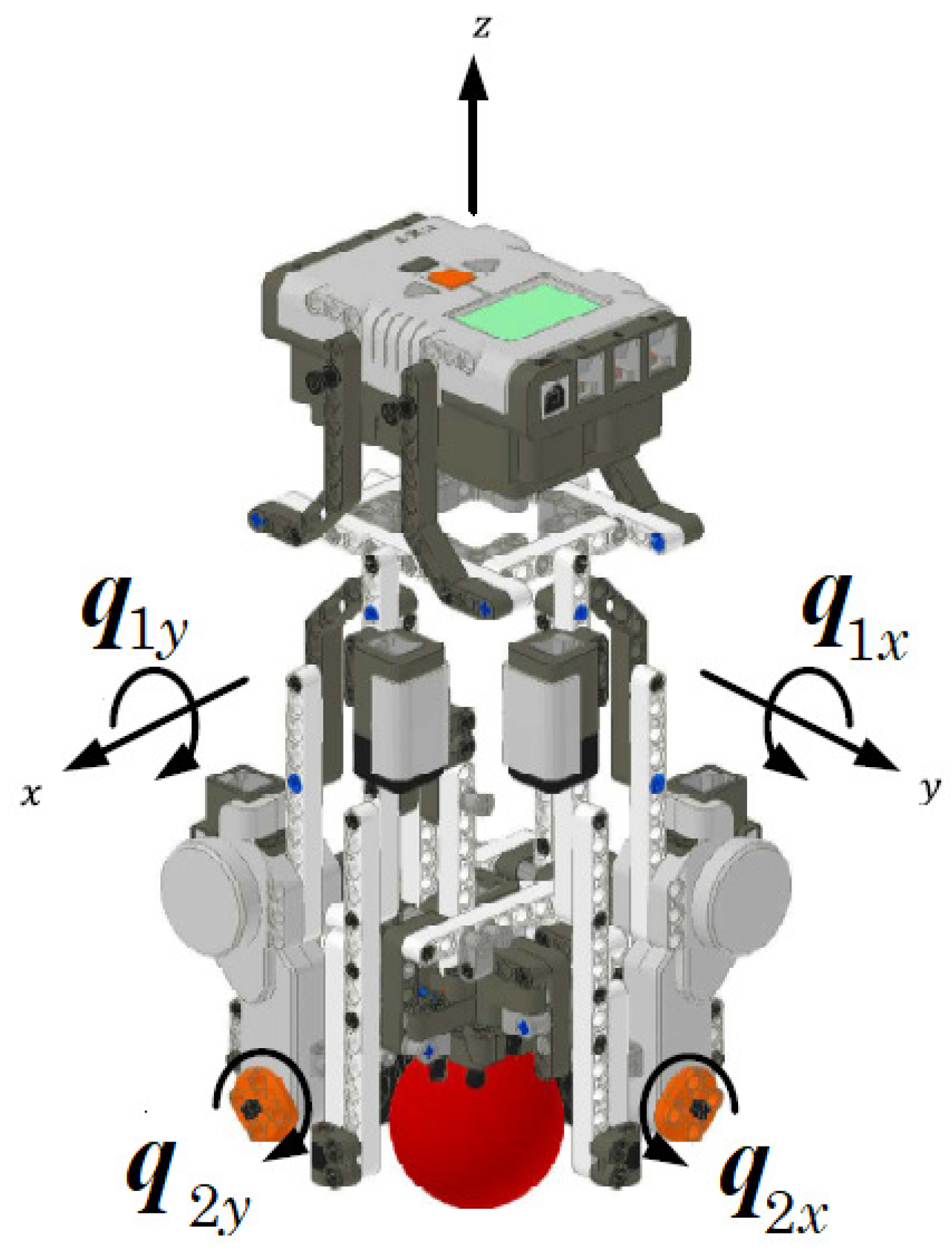
Figure 2.
EV3BRS’s simplified model.
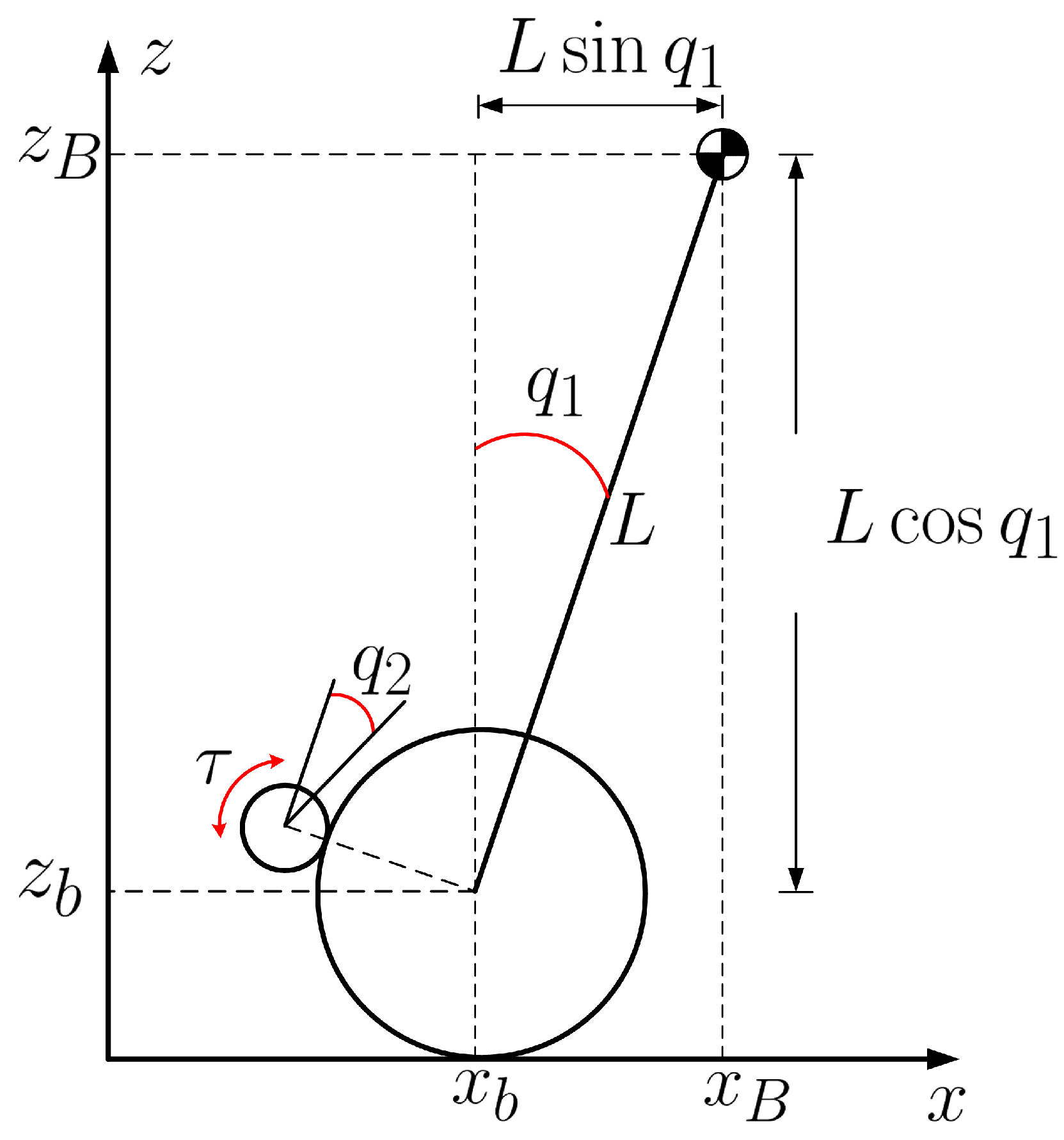
Figure 3.
Membership functions.
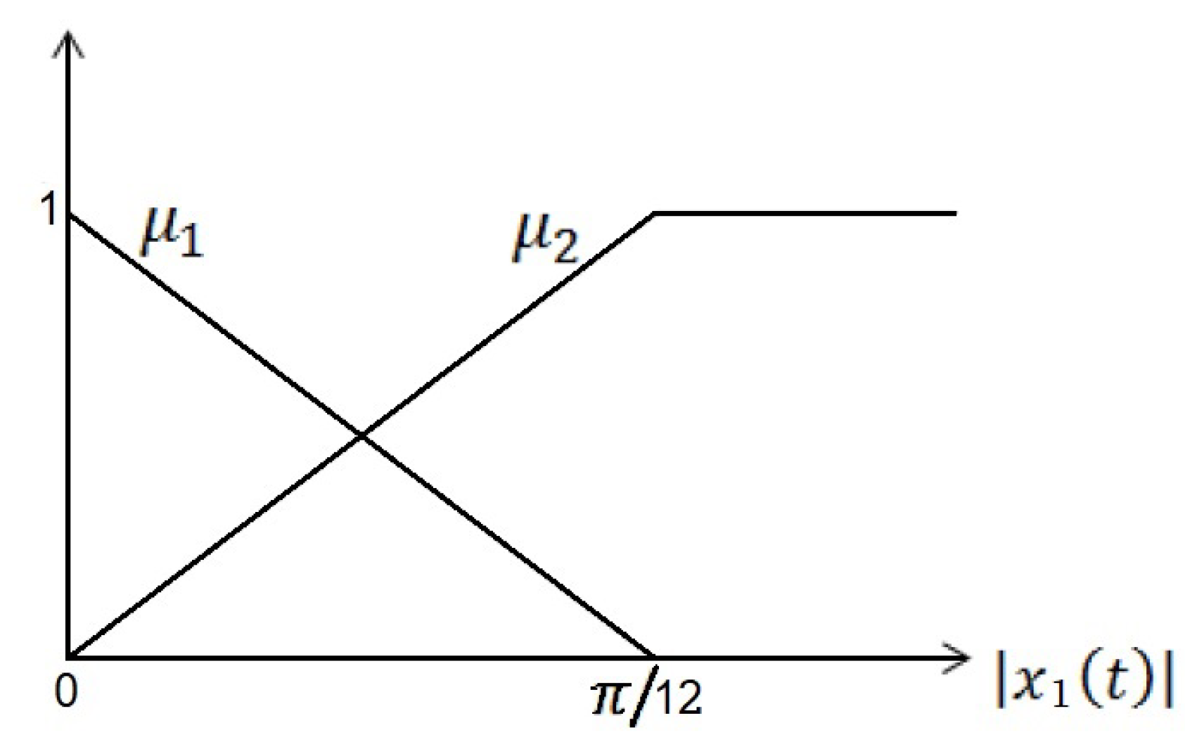
Figure 4.
TSFC scheme.
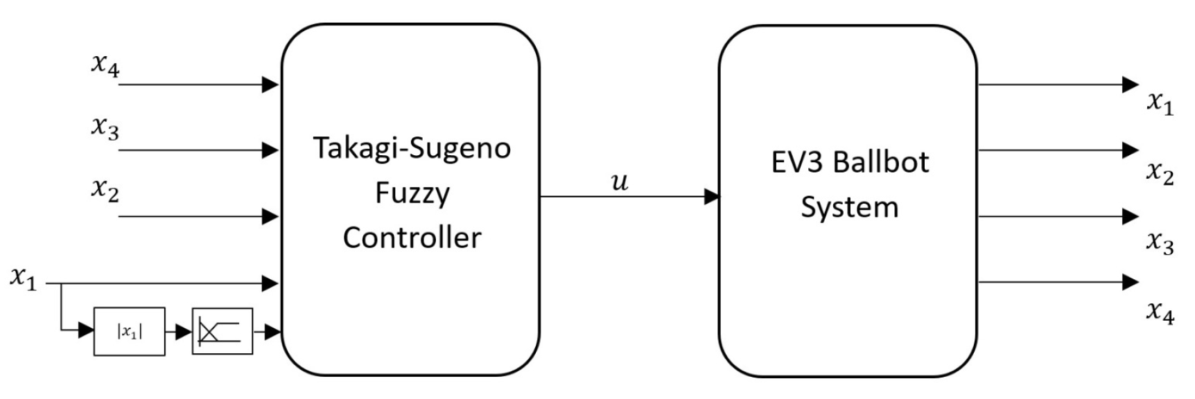
Figure 5.
EV3BRS prototype.
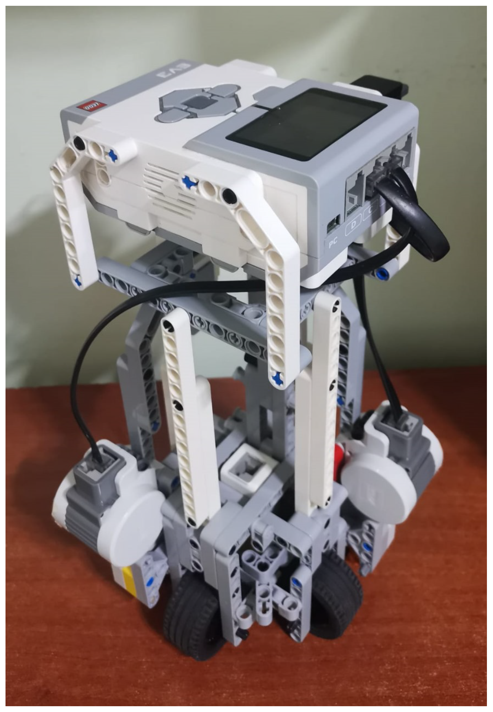
Figure 6.
Experimental setup.
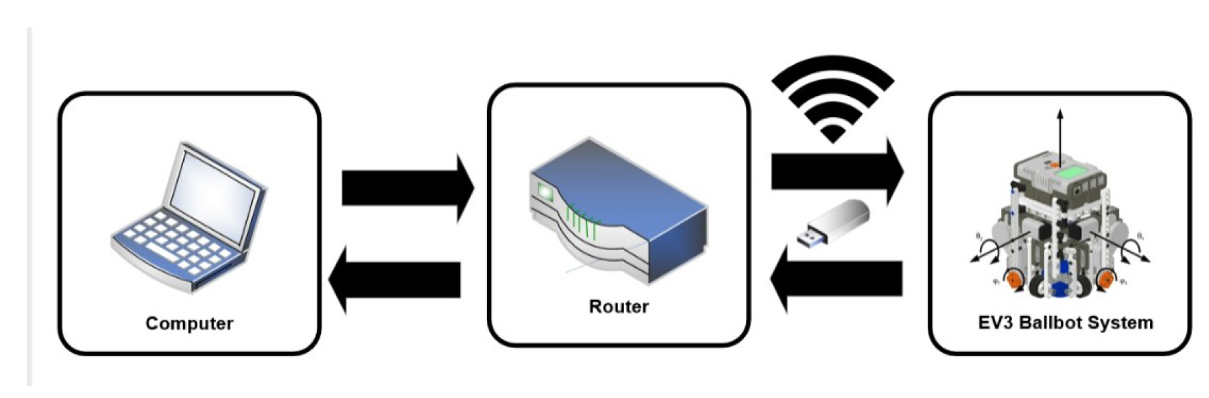
Figure 7.
Dynamics of the EV3BRS’s body around the x-axis.
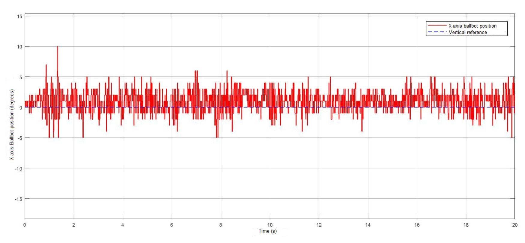
Figure 8.
Dynamics of the EV3BRS’s body around the y-axis.
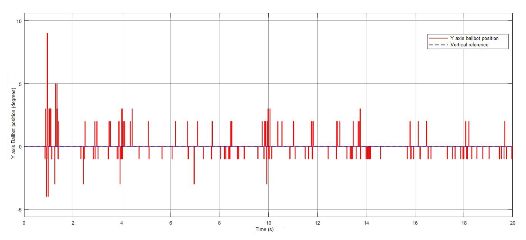
Figure 9.
Dynamics of the rotor shaft around the x-axis.

Figure 10.
Dynamics of the rotor shaft around the y-axis.
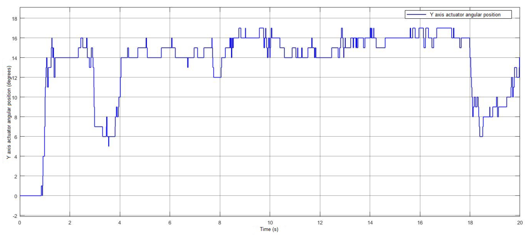
Figure 11.
Control signal from the actuator on the x-axis.
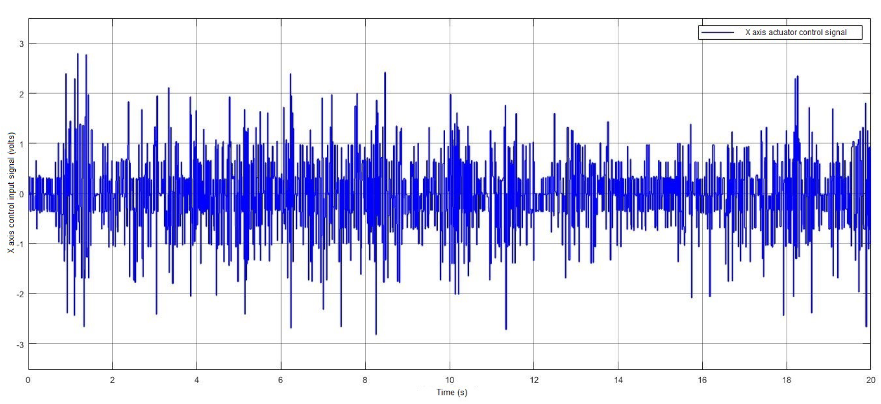
Figure 12.
Control signal from the actuator on the y-axis.
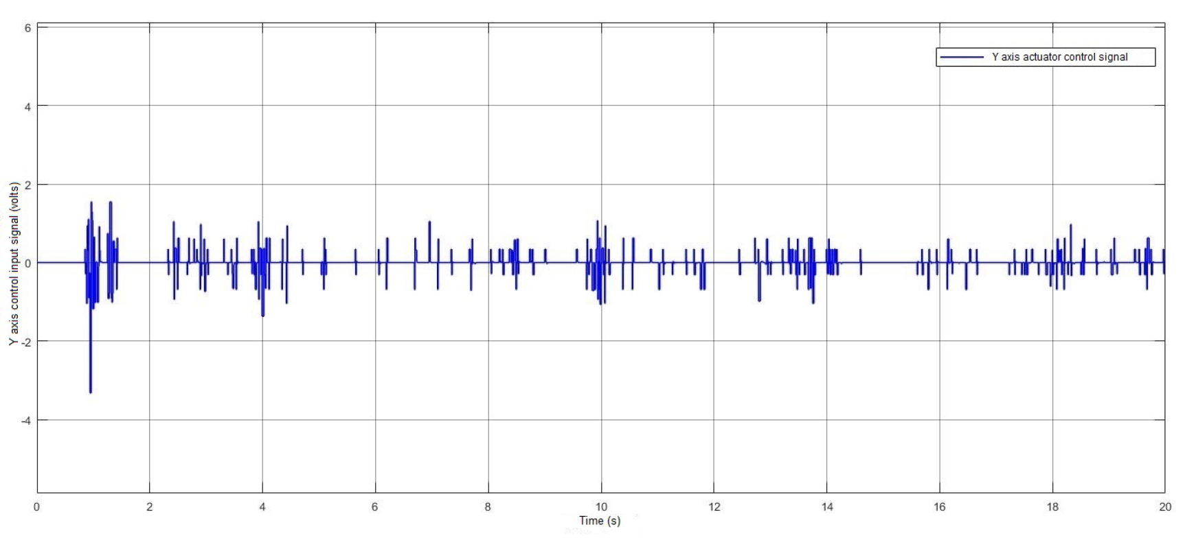

Table 1.
EV3BRS’s Parametric Values.
| Parameter | Symbol | Value | Units |
| Mass of the body | 0.7448 | kg | |
| Mass of the ball | 0.0139 | kg | |
| Radius of the wheel | 0.0222 | m | |
| Radius of the ball | 0.026 | m | |
| Body moment of inertia | kg | ||
| Ball moment of inertia | kg | ||
| Height of the centre of mass | L | 0.155 | m |
| Gravity acceleration | 9.81 | m/ | |
| Gear ratio, motor ball | – | ||
| DC motor moment of inertia | 1× | kg | |
| Friction between body and surface | 0 | Nms/rad | |
| Friction between body and ball | 0.0022 | Nms/rad | |
| DC motor torque constant | 0.317 | Nm/A | |
| DC motor resistance | 6.69 | ||
| DC motor back EMF constant | 0.468 | V s/rad |
Disclaimer/Publisher’s Note: The statements, opinions and data contained in all publications are solely those of the individual author(s) and contributor(s) and not of MDPI and/or the editor(s). MDPI and/or the editor(s) disclaim responsibility for any injury to people or property resulting from any ideas, methods, instructions or products referred to in the content. |
© 2023 by the authors. Licensee MDPI, Basel, Switzerland. This article is an open access article distributed under the terms and conditions of the Creative Commons Attribution (CC BY) license (http://creativecommons.org/licenses/by/4.0/).
Copyright: This open access article is published under a Creative Commons CC BY 4.0 license, which permit the free download, distribution, and reuse, provided that the author and preprint are cited in any reuse.


