1. Introduction
Growing energy demand, coupled with the rapid depletion of fossil fuels and the deterioration of environmental pollution, are driving the transformation of the energy mix [
1,
2,
3,
4,
5]. In order to achieve the goals of carbon peak and carbon neutrality, it is necessary to promote an all-round, full-chain and full-life cycle energy revolution, optimize the energy structure, and build a clean, low-carbon, safe and efficient energy system [
6]. Lithium-ion batteries are one of the most widely used chemical batteries due to their high energy density, low self-discharge rate, and long cycle life, and are widely used in electric vehicles, energy storage, and portable electronics [
7,
8,
9]. Lithium-ion batteries are composed of six parts: cathode material, anode material, separator, current collector, electrolyte, and battery shell. Among them, the cathode material is one of the key factors that determine its performance, which has an important impact on the capacity, service life and cycle performance of the battery, and is also the key to reducing the cost of the battery. However, the performance of currently commercially available lithium-ion batteries is difficult to meet the growing performance requirements of electric vehicles [
10,
11,
12].
In recent years, the layered structure of LiNi
xCo
yMn
zO
2(x≥0.6) cathode material has been gradually applied to the field of electric vehicles and the energy industry due to its high energy density and excellent cycling performance [
13,
14]. High-nickel cathode material can deliver a high capacity of above 200 mAh g
−1, which can effectively match the capacity of the current commercial anode material graphite (372 mAh g
-1), improve the energy density of lithium-ion batteries, and is expected to achieve the goal of 300 Wh kg
-1 energy density of power battery cells [
15,
16].
However, high-nickel cathode materials still face many basic scientific and technical problems, which restrict their commercialization, and the main problems are the cycling performance and stability, including poor thermal stability of crystals, instability of electrolyte interfaces, and poor chemical and mechanical stability of particles [
17,
18,
19]. Therefore, it is necessary to modify the high-nickel cathode material to improve its cycling performance and stability.
In this paper, we review the research progress of high-nickel cathode materials in bulk doping and surface coating. The bulk doping involves the introduction of different ions. Surface coating includes carbon material coating, phosphate coating, fluoride and oxide coating. In addition, the modification method of doping and coating integration is also discussed. Finally, we evaluate the methods summarized in this paper and look forward to the future development direction of high-nickel cathode materials.
2. Materials and Methods
Bulk doping is to improve the stability of layered cathode materials by introducing other elements, mainly including anion doping, cation doping, and multi-ion co-doping. Doping some metal ions with low electrochemical activity in the crystal lattice of high-nickel materials can not only improve the chemical and thermal stability of the material structure, but also improve the electronic conductivity and ionic conductivity at the same time, and increase the output power of the battery. Equivalent cation doping generally does not change the valency of the element, but can make the material structure stable, while the doping of ions with lower valence states will lead to an increase in the valence state of the transition element, that is, the formation of holes, change the band structure of the material, and greatly improve the electronic conductivity of the material [
20].
2.1. Anionic doping
Anionic doping is the introduction of single or polyanion-substitution of O
2- in the crystal lattice by introducing single or polyanionic ions such as F
- [
21,
22] Br
- [
23], N
3- [
24], (BO
3)
3- [
25,
26]. F
- has a better modification effect, because the electronegativity of F
- is greater than that of O
2-, so the bond energy of Li-F is higher than that of Li-O. F
- substitution can effectively reduce the lattice constant, effectively inhibit the dissolution of transition metal elements, and at the same time, F
- can promote the formation of SEI film on the surface of the material to avoid the corrosion of HF, a by-product of electrolyte reaction, and play a role in stabilizing the cathode-electrolyte interface and improving the cycling performance of the material.
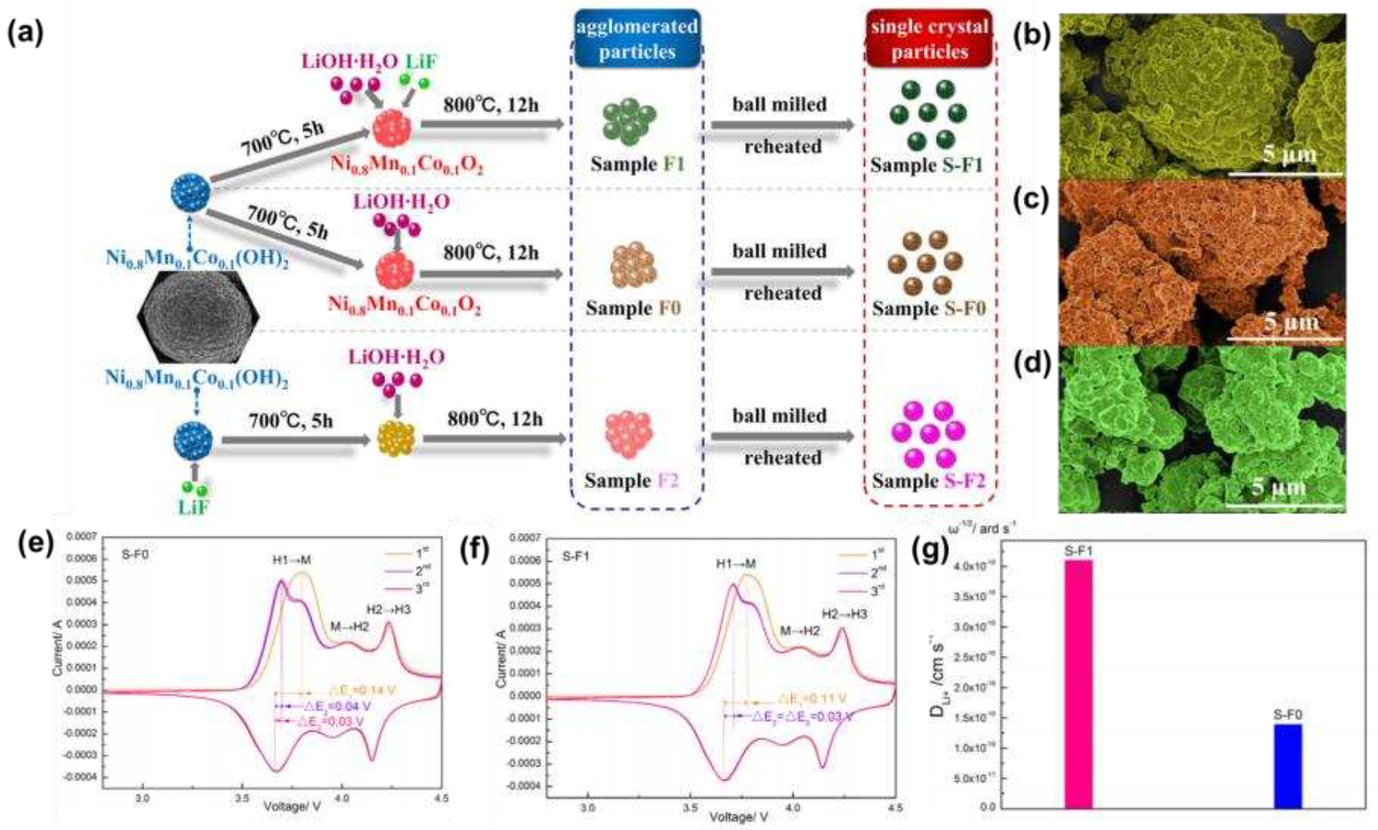
Zhao et al. [
22] successfully synthesized fluorine-doped high-nickel cathode materials, the synthesis schematic diagram was shown in
Figure 1a, and the basic morphology was shown in
Figure 1b-d. XRD analysis showed that the fluorine substitution process did not change the layered structure, but promoted the growth and expansion of unit cells in the c-axis direction, and improved the Li
+ diffusion kinetics. Cyclic voltammetry (CV) (
Figure 1e, f) and lithium-ion diffusion rate plots (
Figure 1g) showed that fluorine substitution can effectively reduce the polarization and migration resistance of lithium-ions, resulting in smoother migration.
He et al. [
23] prepared a Br
- modified LiNi
0.815Co
0.15Al
0.035O
2 cathode material by in-situ doping method for the first time, and found that Br
- doping could reduce the particle size and increase the interlayer distance. When the concentration of Br
- is 0.2 mol%, it could be observed that the potential polarization and R
SEI + R
ct value of the doped material were significantly reduced, and the Li
+ diffusion coefficient increased, and the capacity retention rate was 75.7% after 100 cycles, indicating that the introduction of Br
- can effectively enhance the stability of the material.
Binder et al. [
24] innovatively doped N
3- into Li
1.02 (Ni
0.8Co
0.1Mn
0.1)
0.98O
2 by ammonia treatment (in the presence of oxygen), and found that the introduction of N
3- could expand the interlayer distance of the material structure, significantly improve the rate performance and overall electrochemical performance of the material.
Chen et al. [
25] used H
3BO
3 as a boron source, and (BO
3)
3- gradient doped high-nickel spherical LiNi
0.8Co
0.15Al
0.05O
2 (NCA) cathode materials were obtained after high-temperature sintering. At 1.5 % borate, the material had a capacity retention rate of 96.7% after 200 cycles at 2 C, even under high cut-off potential and higher temperature test conditions, in addition to exhibiting more stable discharge capability and smaller voltage drop.
2.2. Cation doping
Cationic doping is the introduction of K
+ [
27], Na
+ [
28], Mn
4+ [
29], Mg
2+ [
30,
31,
32], Al
3+ [
33], Ti
4+ [
34,
35,
36], V
4+ [
37,
38], Zr
4+ [
39], etc. in the substitution structure of Li
+ or transition metal ions. It can effectively reduce the mixing of Li
+/Ni
2+ cations, inhibit the multiphase transition in the charge-discharge process, and improve the stability of the crystal structure, thereby improving the cyclic stability of the material.
Xu et al. [
27] successfully synthesized Li
1-xK
xNi
0.8Co
0.1Mn
0.2 (LKNCM) by introducing K
+ into NCM811 by molten salt-assisted growth method, and found that it had a low degree of Li
+/Ni
2+ mixing and ordered layered structure. It still had a capacity retention rate of more than 95% after 100 cycles at 0.1 C and 95.2% capacity retention even after 180 cycles at 10 C, with excellent cycling stability, which was attributed to the K
+ doping ability to effectively inhibit side reactions and electrolyte decomposition in charge-discharge cycles.
Tao et al. [
30] prepared LiNi
0.8-xCo
0.1Mn
0.1Mg
xO
2 by co-precipitation method, which showed low Li
+/Ni
2+ cation mixing at 2.7-4.5 V voltage, high structural stability and cycling stability, and the discharge capacity could reach 163.5 mAh g
-1 after 200 cycles at 1 C, and the capacity loss rate did not exceed 20%. Bai et al. [
31] used nano-silica sand grinding method to prepare Mg
2+-doped NCA, and found that the polarization of the NCA electrode was slightly reduced, the lithium ion diffusion was enhanced, and the cycle retention rate was improved. Lv et al. [
32] introduced Mg
2+ into Ni
0.83Co
0.12Mn
0.05 by co-precipitation-sintering. The results showed that Mg
2+ doping can significantly improve the cycling stability of the material. When the doping amount was 0.96%, the initial discharge capacity was 199.7 mAh g
-1, the capacity retention rate was 87.2%, and the structure was not damaged after cycling.
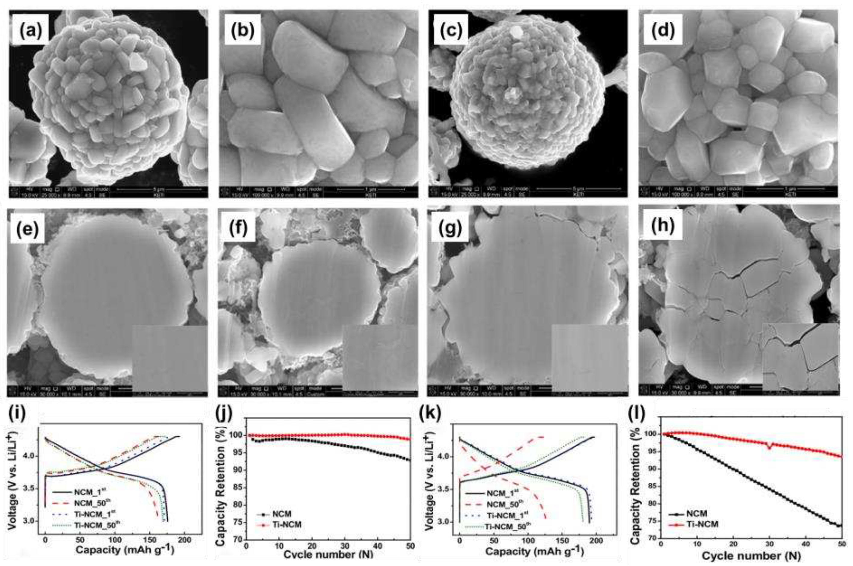
Song et al. [
35] doped high-nickel LiNi
0.7Co
0.15Mn
0.15O
2 materials in solution. As shown in
Figure 2a-d, the material morphology remained similar after Ti
4+ doping, but the lattice parameters of the layered structure were slightly shifted to the larger value by analyzing XRD. Analysis of electrochemical performance (
Figure 2i-l) showed that Ti
4+ doping enhanced cycling performance at 25°C. In addition, when the temperature was increased to 60°C, the capacity retention rate of Ti-doped material was greatly improved, and it was still 95% after 50 cycles. This was attributed to better retention of the compressive strength of the particles and Ti
4+ doping to delay crack formation within the particles (
Figure 2e-h).
2.3. Multi-ion co-doping
Multi-ion co-doping is the use of multiple ions for modification, which can combine the advantages of multiple ions and maximize the comprehensive electrochemical performance of the material. For example, PO
43-/Mn
4+ [
40], P
3-/F
- [
41,
42], Mg
2+/Al
3+ [
43,
44], Al
3+/Fe
3+ [
45], Mg
2+/F
- [
46], Na
+/F
- [
47].
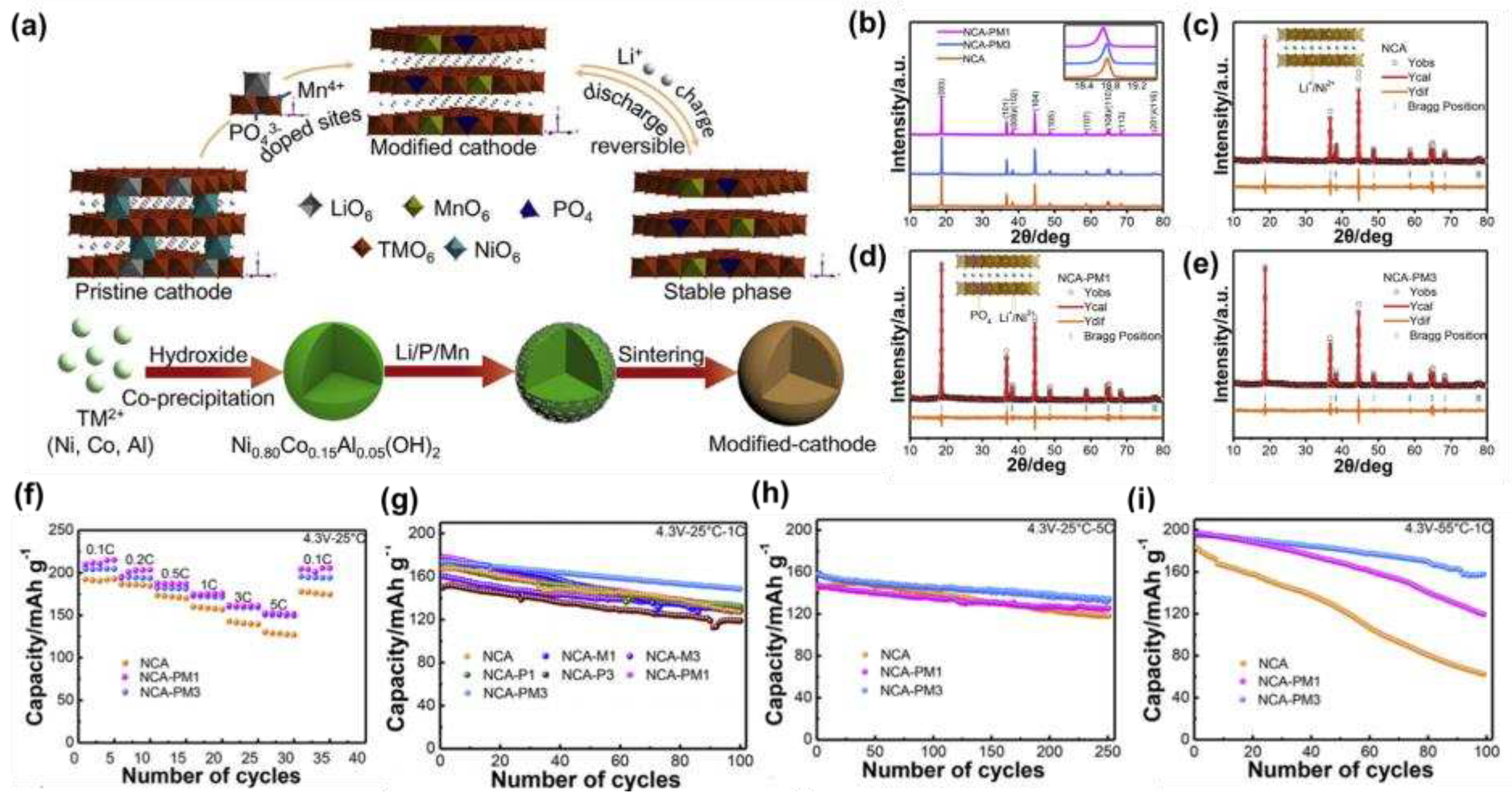
Qiu et al. [
40] synthesized LiNi
0.8Co
0.15Al
0.05O
2 doped with PO
43- and Mn
4+ by high-temperature solid-state reaction. As shown in
Figure 3a, a schematic diagram of the synthesis of the modified material, the crystal structure showed that the co-doping of PO
43- and Mn
4+ could expand the Li
+ transport channel and reduce lattice defects, which could also be illustrated by the XRD of
Figure 3b-e to the low angle offset. The electrochemical performance was tested and found that the modified sample had good rate performance (
Figure 3f), and that the NCM-PM
3 had a capacity of 204 mAh g
−1 at 0.1 C at 2.7-4.3 V, and a capacity retention rate of 85.5% after 100 cycles at 1C (
Figure 3g), and a capacity of 157.8 mAh g
−1 even at a high current of 5 C (
Figure 3h). In addition, even at a high temperature of 55°C, the capacity of NCM-PM
3 was maintained at 80.9% after 100 cycles at 1 C (
Figure 3i), and the excellent cycling stability was attributed to the stabilizing effect of Mn
4+ and PO
43- that inhibited structural degradation during cycling.
Yuan et al. [
41] used LiPF
6 as a dopant to co-dop P and F into the structure of NCM811 material, and found that the d spacing of the material increased, the surface stability was enhanced, and the cycling performance was greatly improved.
Xiao et al. [
43] co-doped Mg
2+ and Al
3+ in NCM811 and found that the double doping could expand the fusion channel of Li
+ and reduce the degree of cation mixing, thereby inhibiting the structural degradation during cycling and improving the structural stability during cycling.
3. Surface coating
Surface coating refers to coating a layer of chemically stable material on the surface of the material to block the direct contact between the electrolyte and the cathode material, so as to inhibit the dissolution and corrosion of the electrolyte on the cathode material and reduce the side reactions. Surface coating can improve the stability of the surface structure of the material, promote the transfer of electrons on the surface of the material, and prolong the service life of the material. At present, commonly used coating materials include carbon materials (amorphous carbon [
48,
49,
50], graphene [
51,
52,
53], carbon nanotubes [
54,
55]), phosphate (Li
3PO
4 [
56,
57,
58], LiFePO
4 [
59], MnPO
4 [
60]), fluoride (CaF
2 [
61], AlF
3 [
62], LiF [
63]), oxides (LiBO
3 [
64], LiWO
3 [
65], Li
2TiO
3 [
66], WO
3 [
67], SiO
2 [
68], Al
2O
3 [
69], CeO
2 [
70]) etc.
3.1. Carbon materials coating
The high-nickel ternary cathode material has a high nickel content, large theoretical specific capacity and low cost, which is a promising cathode material for lithium-ion batteries, but there is still a mixed discharge of Ni2+ and Li+ that has an impact on its commercial application, and the low Co and Mn content will also adversely affect the cycling performance and rate performance of the material. Carbon materials have excellent electrical conductivity and large specific surface area. The coating modification of high-nickel ternary cathode materials by carbon materials can effectively improve the electrochemical properties of the materials.
3.1.1. Amorphous carbon
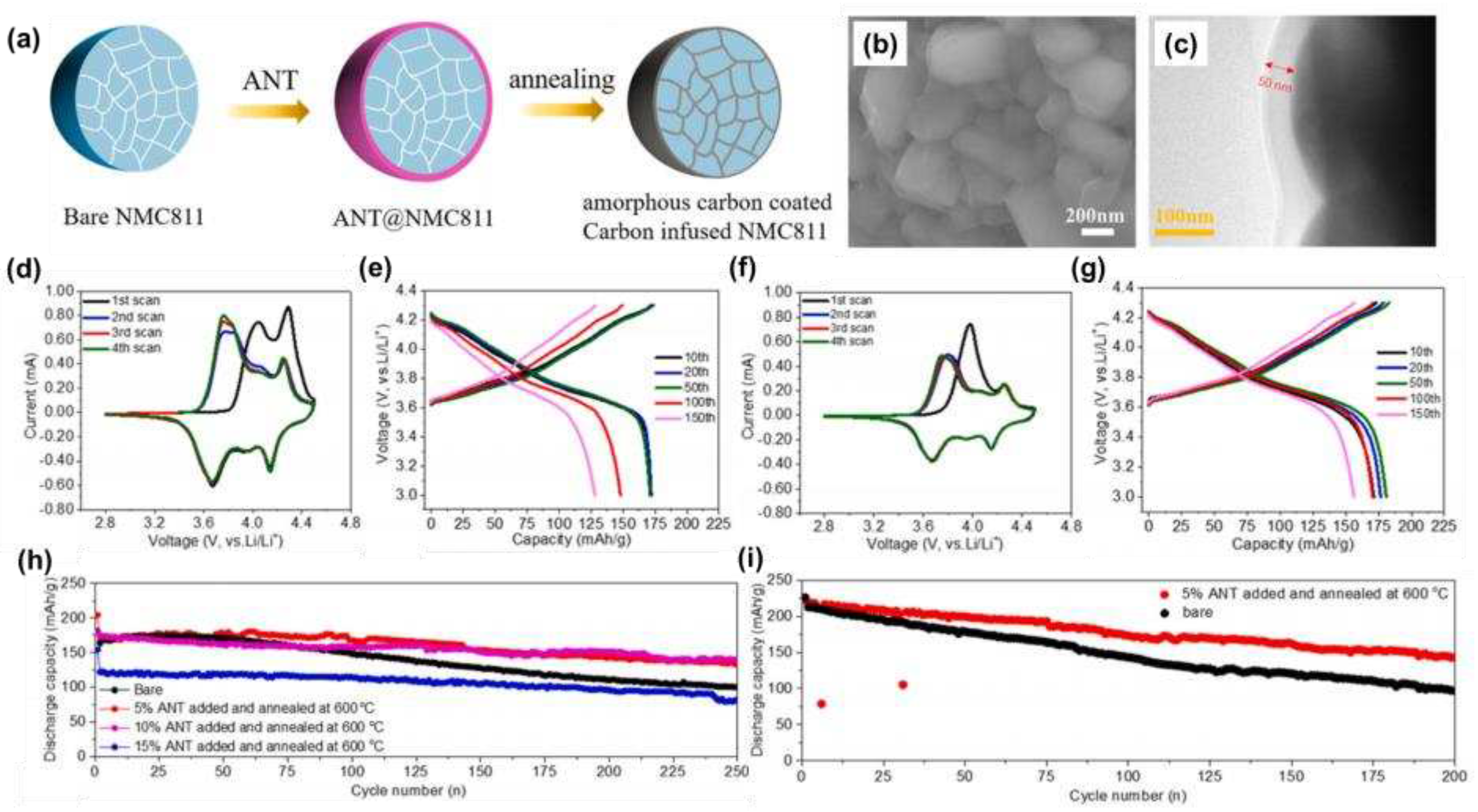
Liang et al. [
50] used a liquid phase polymer acrylonitrile telomer (ANT) as a precursor to coat an amorphous carbon layer on a high-nickel cathode, and the synthesis process was shown in
Figure 4a, and the related morphology was shown in
Figure 4b. When the ANT addition was 5 wt% and the annealing temperature was 600 °C, we could clearly see the presence of an amorphous carbon layer with a thickness of 50 nm in the TEM image (
Figure 4c). Comparing the CV curves (
Figure 4d, f), it could be found that the anode peak positions of 4.08 V and 4.31 V were reduced and the peak area was reduced after the amorphous carbon layer was coated, indicating that the amorphous carbon coating reduced the relative electrochemical polarity and inhibited the side reactions at high pressure. Comparing the charge-discharge curves (
Figure 4e, g) and the cycle curves (
Figure 4h, i), it can be found that the coating of the amorphous carbon layer could improve the cyclic stability of the material and reduced the voltage attenuation.
Qiu et al. [
49] successfully prepared NCM-N
2, an amorphous N-nano-carbon shell-coated material, in an N
2 atmosphere, and found that its cycling stability was significantly improved. The capacity retention rate was 96.64% after 40 cycles at 0.1 C and 95.06% after 100 cycles at 1 C, which was attributed to the fact that the amorphous N-nanocarbon shell could inhibit the occurrence of side reactions, improve the conductivity, and effectively increase the diffusion rate and charge migration rate of Li
+. Kathribail et al. [
48] successfully inducted an amorphous carbon coating at NCM622 by furfuryl alcohol polymerization followed by calcination. It was found that the heat treatment could significantly improve the cycling stability, and the capacity retention rate could still reach 89.42% after 400 cycles of 2 C current cycle a heat treatment at 400°C, which was much higher than that of the uncoated sample (81.38%).
3.1.2. Graphene
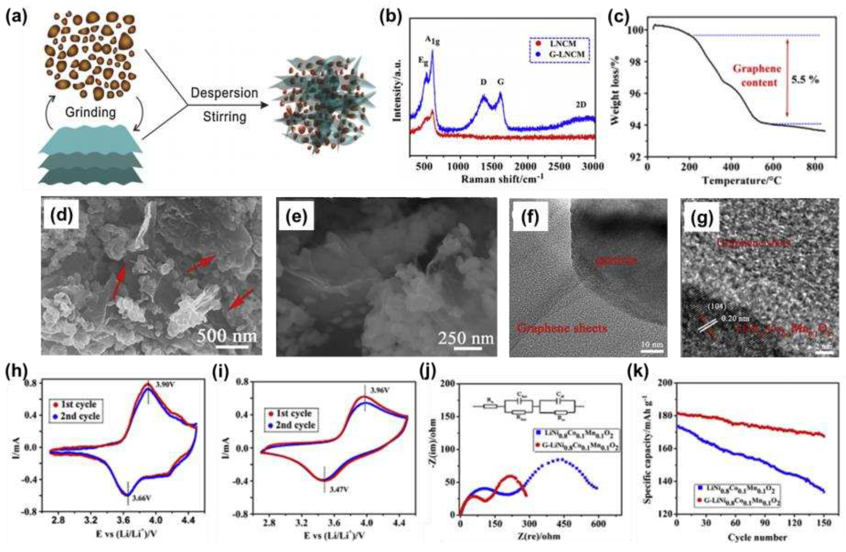
As shown in
Figure 5a, Jan et al. [
52] successfully synthesized a layered NCM811-graphene composite, with Raman spectroscopy (
Figure 5b) confirming the presence of graphene and a TG curve (
Figure 5c) measuring a graphene content of 5.5%. The presence of graphene was clearly visible in SEM images (
Figure 5d, e), and TEM images (
Figure 5f, g) further illustrated the success of the coating. The CV curves showed that the redox peak potential difference of the graphene composites was reduced (
Figure 5h, i), indicating that the introduction of graphene nanosheets could reduce the electrode polarization. The EIS image (
Figure 5j) confirmed a significant reduction in R
SEI and R
ct, and a significant improvement in electrode kinetics. Further testing of the cycling performance showed that after 150 cycles at 1 C, the capacity still had 167.5 mAh g
-1 and the retention rate was 92.2%.
Ning et al. [
51] prepared a homogeneous redox graphene-coated NCM811 (PG-NCM) by physical mixing, and found that the capacity could reach 194.1 mAh g
−1 at 1 C, the capacity retention rate was 92.8% after 100 cycles, and the capacity could reach 122.1 mAh g
−1 even at 10 C.
Park et al. [
53] constructed a conformal graphene coating on the surface of NCA, which could not only enhance the conductivity of the material and inhibit the degradation of the cathode surface, but also greatly improve the cycling stability, making the material close to the volume capacity and specific capacity limits of the cathode of lithium batteries at the same time.
3.1.3. Carbon nanotubes
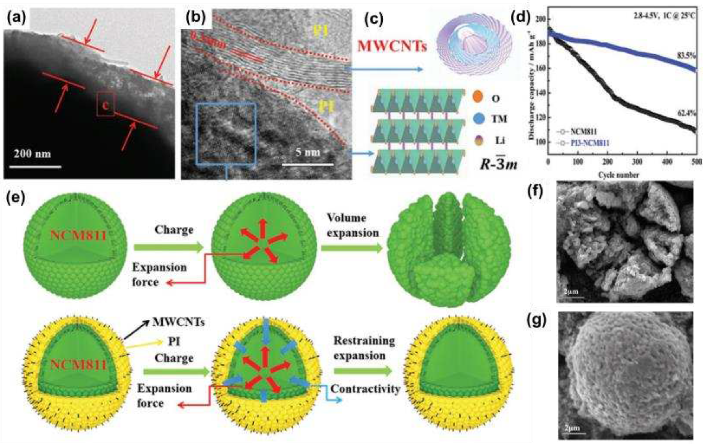
Zha et al. [
54] prepared the PI3-NCM811 cathode by combining multi-walled carbon nanotubes (MWCNTs), polyimide (PI), and NCM811. The TEM image in
Figure 6a showed that the microspheres of PI3-NCM811 were encapsulated by PI/MWCNTs and are approximately between 150-180 nm thick.
Figure 6b showed that the lattice fringe of NCM811 was 0.47 nm, which corresponded to the rhombic phase layered structure of NCM811(003) in
Figure 6c. The electrochemical performance test showed that the capacity retention rate of the PI3-NCM811 cathode was 83.5% after 500 cycles at 1 C at 2.8-4.5 V (
Figure 6d), which was much higher than that of the original sample (62.4%), and the excellent stability was not only due to the coating inhibiting the electrode material from contacting the electrode material and the electrolyte and preventing the material from being corroded by the electrolyte, but also that the PI/MWCNTs composite coating inhibited the cracking damage caused by the expansion of the crystal volume during discharge (
Figure 6e-g).
Hwang et al. [
55] successfully coated NCM811 with a conductive three-dimensional carbon network layer (consisting of 6-amino-4-hydroxy-2-naphthalenesulfonic acid -functionalized rGO and carbon nanotubes). The coating could enhance the electrical conductivity, inhibit the occurrence of irreversible phase changes and side reactions, and achieve a stable high-rate electrochemical reaction. The capacity was maintained at 88% after 100 cycles at 1 C.
3.2. Phosphate coating
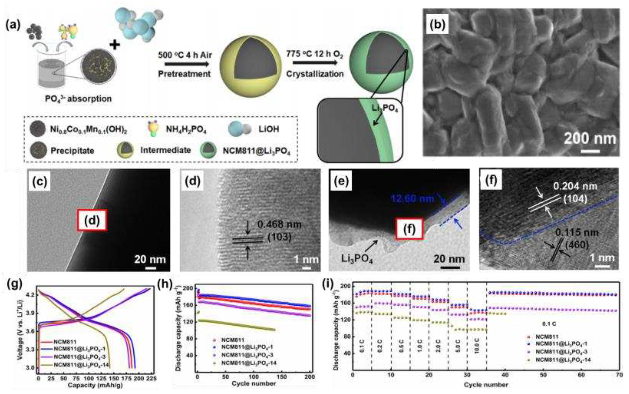
As shown in
Figure 7a, Zhang et al. [
57] prepared an NCM811@Li
3PO
4 coated with a solid electrolyte lithium phosphate in situ with the basic morphology shown in
Figure 7b, and found that the particle surface became rough. As could be seen from the TEM images (
Figure 7c, d), NCM811 had a typical layered structure, with a thickness of approximately 12.6 nm at the Li
3PO
4 surface, and good overall crystallinity (
Figure 7e, f). When the coating amount of Li
3PO
4 was 1 mol%, it had the best electrochemical performance. The initial discharge capacity was 192.4 mAh g
-1 (
Figure 7g), and after 200 cycles at 1 C, the capacity was 157.8 mAh g
-1, and the capacity retention rate was 86.7% (
Figure 7h). In addition, the NCM811@Li
3PO
4 had good magnification performance (
Figure 7i). The good electrochemical performance was attributed to the coating relieving stress-induced microcrack evolution, slowing down HF corrosion, and maintaining a high lithium-ion diffusion coefficient.
Zhu et al. [
56] successfully constructed a Li
3PO
4 coating on the surface of NCM811 using the reaction between residual lithium and (NH
4)
2HPO
4, and found that the material properties were significantly improved, which was attributed to the formation of the coating to eliminate residual lithium on the surface, promote the diffusion of lithium ions, inhibit the reaction of surfactants with CO
2 and H
2O, and inhibit the occurrence of side reactions.
Zhuang et al. [
59] prepared Li
3FePO
4/C-coated NCM811 by simple ball milling and found that the coating could inhibit the change of particle volume during cycling and reduce the occurrence of side reactions. When the LFP/C coating amount was 1 wt%, it had good cycle stability and rate performance. The volume retention rate after 300 cycles at 25°C was 61.6%, which was significantly higher than the 48.63% retention rate of the bare NCM811.
3.3. Fluoride coating
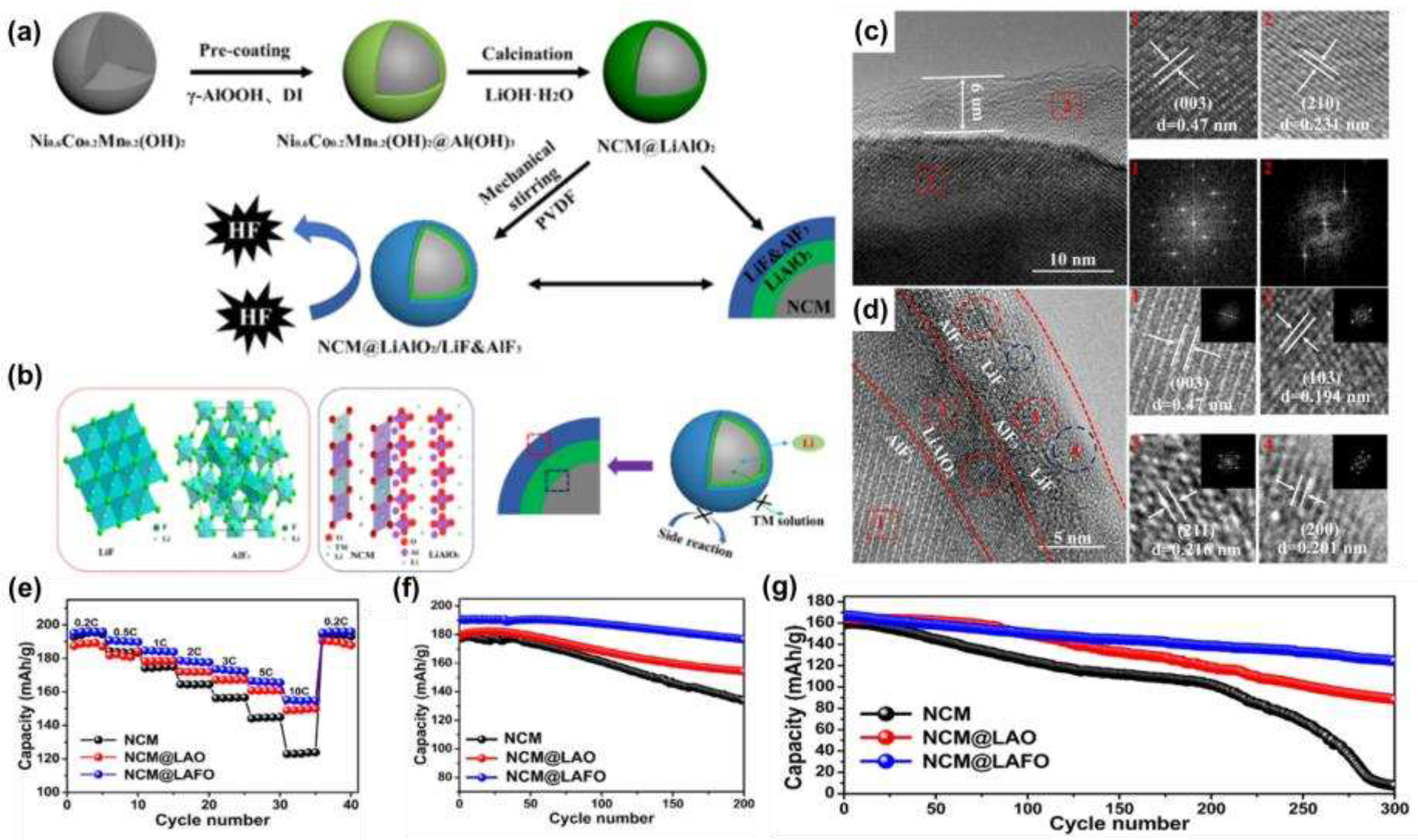
Wang et al. [
62] reported a modification strategy for the synthesis of a LiAlO
2/LiF&AlF
3 (LAFO) hybrid coating on the surface of NCM622, and the material preparation flow was shown in
Figure 8a. The crystal structure of the NCM@LAFO was shown in
Figure 8b, from which it could be seen that LiAlO
2 was tightly fixed on the surface of NCM, while the LiF and AlF
3 layers were fixed on the surface of LiAlO
2, and this structural distribution could effectively slow down the corrosion of HF and alleviate the structural degradation and intergranular cracks during cycling. The structural distribution of NCM- LiAlO
2-LiF&AlF
3 could also be seen in
Figure 8b, c. The electrochemical properties were tested and found to have excellent rate performance (
Figure 8e) and cycling stability, with a capacity retention rate of 93.01% after 200 cycles at 1 C (
Figure 8f) and 74.5% after 300 cycles at 5 C (
Figure 8g).
Dai et al. [
61] designed an ultra-thin calcium fluoride coating on the surface of NCM811 with a thickness of only 5-12 nm. When the calcium fluoride content was 3 wt%, the modified sample exhibited the best cycling capacity and rate performance. In addition, the calcium fluoride coating significantly improved the high-temperature stability of the cathode material, and the capacity retention rate was 79.68% after 50 cycles at 1 C at 55°C, far exceeding the 59.32% of the original sample.
3.4. Oxide coating
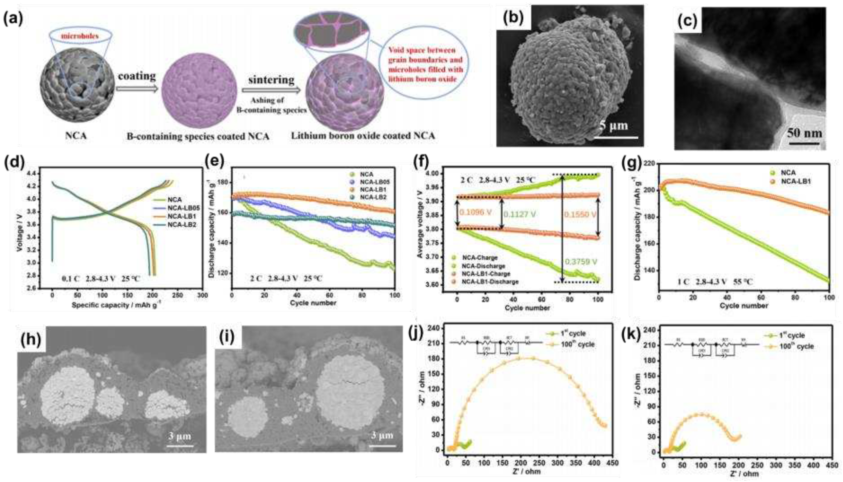
As shown in
Figure 9a, Du et al. [
64] prepared a uniform layer of lithium boron oxide coating from residual lithium on the surface of NCA, and the basic morphology was shown in
Figure 9b. Through the TEM image (
Figure 9c), it was found that the lithium boron oxide film not only uniformly covered the surface of NCA, but also closely connected with the main particles in the secondary particles, preventing the degradation of the microstructure of the material. The charge and discharge curves at 0.1 C (
Figure 9d) and the cycling performance at 2 C (
Figure 9e) showed that NCA-LB1 had suitable electrochemical properties, and the average discharge voltage decreased by only 0.0385 V after 100 cycles (
Figure 9f), indicating that it had good electrochemical stability. The performance of NCA-LB1 at 55 °C at 1 C was further tested (
Figure 9g) and it was found that its capacity retention rate was 90.87% after 100 cycles, much higher than the 65.17% of the original NCA cathode.
The excellent stability at high temperatures was attributed to the fact that the lithium boron oxide film mitigated electrolyte penetration into the particles, reduced the formation of SEI films within the NCA spheres, and thus reduced the formation of microcracks inside the secondary particles (
Figure 9h, i). This result could also be illustrated by the EIS image after 100 cycles (
Figure 9j, k), where the R
SEI of the NCA-LB1 electrode barely changed and the R
ct increased significantly.
Cho et al. [
68] coated the surface of NCM622 with a layer of SiO
2, and found that the cycling performance of the modified material was greatly improved at a high temperature of 60°C, and the capacity retention rate was 93% after 50 cycles. This was attributed to the fact that the coating inhibited the growth of interfacial impedance during cycling, slowing down the corrosion of HF.
4. Integrated treatment of doping and coating
Due to the complexity of the process, it is still a great challenge to achieve the structural and interfacial stability of nickel-rich materials at the same time. Therefore, researchers explore the integrated strategy of doping and coating, and realize the controllable preparation of stable cathode materials by modifying the doping and coating of the same material, while regulating the crystal structure and improving the interfacial stability of the material.
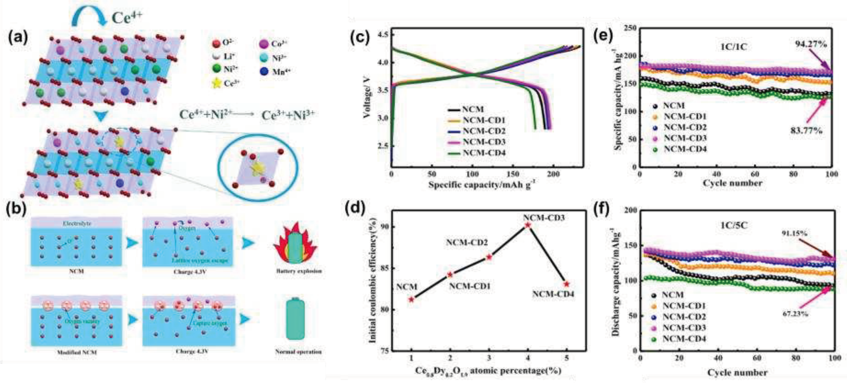
Wang et al. [
71] successfully introduced fluorite-type oxygen ion conductors into the surface of pristine particles, which ensured the stability of the electrochemical process under a special process environment. In this method, the oxygen ion conductor Ce
0.8Dy
0.2O
1.9 containing oxygen vacancies was coated on the surface of the material by in-situ co-precipitation, which improved the stability of the cathode material, and obtained a material with high capacity, good safety and high electronic conductivity, which was a modification strategy that combines the dual advantages of surface coating and element doping. As shown in
Figure 1a, the oxygen ion conductor contained the rare earth element cerium, and there were two valence states of Ce
3+ and Ce
4+, which could be converted into each other in chemical processes. Ce
4+ had strong oxidation properties, which could oxidize Ni
2+ to Ni
3+, reduce the mixed discharge of Li
+/Ni
2+, and further improve the first-turn cycle efficiency and structural stability of battery materials. In addition, a large number of oxygen vacancies existed in the Ce
0.8Dy
0.2O
1.9 crystal, which brought better results in inhibiting the release of oxygen and improving the safety performance of the material, schematic diagram shown in
Figure 1b.
The results of the electrochemical performance test in
Figure 2c-f showed that among the various oxygen ion conductors added, the 3 wt% oxygen ion conductor had the most significant effect on improving the electrochemical performance of the material. The first-pass coulombic efficiency and cycling performance of the original sample were 81.23% and 83.77%, compared to 90.24% and 94.27% for the NCM-CD3 sample. The reason for this was that the reaction between Ce
4+ and Ni
2+ alleviates the phenomenon of cation mixing, and showed excellent cycling performance. In addition, a large number of oxygen vacancies in Ce
0.8Dy
0.2O
1.9 crystals could effectively trap unstable oxygen-containing substances (such as O
2-, O
- and O
22-) generated in the deep lithium removal process, the release of oxygen was reduced, and the stability and safety of the material were well improved.
Figure 10.
(a) Schematic diagram of cation disorder of NCM and Ce0.8Dy0.2O1.9 modified NCM; (b) Schematic illustration of the oxygen vacancies in the Ce0.8Dy0.2O1.9 modified layer enhancing the structural stability of Ni-rich materials; (c) Initial chargedischarge curves between 2.8 and 4.3V at 0.1 C; (d) Initial coulomb efficiency; (e) The differential capacity curves in the first cycle; (f) Cycling performance at 1 C.
Bao et al. [
72] controlled the post-annealing temperature of the ultra-thin ZrO
2 films prepared by ALD, and the Zr
4+ layered oxides could be surface-doped to accelerate charge transfer while providing adequate protection. Using single crystal NCM622 as the model material, it was found that the surface Zr
4+ doping combined with ZrO
2 coating could improve the cycling performance and rate performance. Surface doping by controllable post-annealing of ALD surface coatings revealed an attractive approach to the development of stable and Li
+ conductive interfaces for monocrystalline cell materials.
Ran et al. [
73] used a gradient phosphate polyanion doping strategy to enhance the electrochemical performance of NCM622 cathode materials. This strategy synergistically realized the gradient doping of phosphate polyanions and the in-situ coating of Li
3PO
4 coatings. Gradient doping improved the cycling stability and rate performance of NCM622, and the capacity retention rate of the modified sample reached 92.9% at high cut-off voltage (4.5 V) and high temperature (55°C).
Zhang et al. [
74] modified the internal and surface structure of the high-nickel NCM811 cathode material by employing the rare element Y doping. The coating of the surface lithium-ion conductor LiYO
2 as a surface protector inhibited the side reactions, and the gradient Y
3+ doping supported the crystal structure, showing a synergistic effect in improving the electrochemical performance of the cathode material, with a capacity retention rate of up to 98.4% after 100 cycles at 2.8-4.5 V.
5. Conclusions
High nickel cathode materials have the advantages of high energy density and high safety, but there are also problems of cation mixing and poor stability that need to be solved, which will adversely affect the commercial application of high nickel cathode materials. In this paper, the main modification methods of high-nickel cathode materials are summarized, such as ion doping and surface coating. Although the cycling performance and thermal stability of the modified materials have been greatly improved, these methods cannot fully solve all the problems existing in high-nickel cathode materials.
In the future, one of the main directions for the development of high-nickel cathode materials is co-modification, such as element doping, surface coating and structural design, which can improve the structural stability of materials and reduce the degree of cation mixing through element doping. By reducing the side reactions between the cathode material and the electrolyte through surface coating, we can jointly solve the problems of improving surface sensitivity and oxygen evolution and transition metal ion migration.
In addition, the introduction of oxygen vacancies on the surface of the particles can adsorb and store oxygen, the generation of oxygen is inhibited, the process of reversible redox of oxygen ions in the electrochemical process can be better carried out, and the thermal stability of battery materials is also improved. Since the diffusion of lattice oxygen vacancies in the bulk phase of the material and the aggregation of specific crystal planes are the direct causes of high-temperature phase transformation gas production and crack and final rupture of oxide cathode materials, the irreversible oxygen loss reaction at the interface can be inhibited by the surface coating strategy, so as to effectively reduce the generation of lattice oxygen vacancies in the process of cycling, inhibit the diffusion and accumulation process of lattice oxygen vacancies from the source, and finally achieve the effect of improving particle stability.
In summary, it is difficult for a single modification strategy to take in to account the needs of improving the structural stability, energy density, and rate performance of materials at the same time, so the comprehensive application of various modification strategies is crucial. It is believed that with the joint efforts of future researchers, high-nickel cathode materials can be better applied to lithium-ion batteries and conform to people’s expectations for battery development in the new energy era.
Conflicts of Interest
The authors declare no conflict of interest
References
- Sasirekha, C.; Arumugam, S.; Muralidharan, G. Green synthesis of ZnO/carbon (ZnO/C) as an electrode material for symmetric supercapacitor devices. Appl. Surf. Sci 2018, 449, 521–527. [Google Scholar] [CrossRef]
- Wu, M. K.; Chen, C.; Zhou, J. J.; Yi, F. Y.; Tao, K.; Han, L. MOF-derived hollow double-shelled NiO nanospheres for high-performance supercapacitors. J. Alloys Compd. 2018, 734, 1–8. [Google Scholar] [CrossRef]
- Nitta, N.; Wu, F. X.; Lee, J. T.; Yushin, G. Li-ion battery materials: present and future. Materials Today 2015, 18, 252–264. [Google Scholar] [CrossRef]
- Chu, S.; Cui, Y.; Liu, N. The path towards sustainable energy. Nat. Mater. 2017, 16, 16–22. [Google Scholar] [CrossRef]
- Ahmadi, L.; Young, S. B.; Fowler, M.; Fraser, R. A.; Achachlouei, M. A. A cascaded life cycle: reuse of electric vehicle lithium-ion battery packs in energy storage systems. Int. J. Life Cycle Assess. 2017, 22, 111–124. [Google Scholar] [CrossRef]
- Schmuch, R.; Wagner, R.; Horpel, G.; Placke, T.; Winter, M. Performance and cost of materials for lithium-based rechargeable automotive batteries. Nat. Energy 2018, 3, 267–278. [Google Scholar] [CrossRef]
- Tan, X. R.; Zhang, M. L.; Li, J.; Zhang, D. Y.; Yan, Y. X.; Li, Z. M. Recent progress in coatings and methods of Ni-rich LiNi0.8Co0.1Mn0.1O2 cathode materials: A short review. Ceram. Int. 2020, 46, 21888–21901. [Google Scholar] [CrossRef]
- Sari, H. M. K.; Li, X. F. Controllable Cathode-Electrolyte Interface of Li[Ni0.8Co0.1Mn0.1]O2 for Lithium Ion Batteries: A Review. Adv. Energy Mater. 2019, 9, 1901597. [Google Scholar] [CrossRef]
- Jiang, L. Q.; Zhang, X. F.; Chen, Y. J.; Qiao, L.; Lu, X. L.; Tian, X. Modified polypropylene/cotton fiber composite nonwoven as lithium-ion battery separator. Mater. Chem. Phys. 2018, 219, 368–375. [Google Scholar] [CrossRef]
- Xu, B.; Qian, D. N.; Wang, Z. Y.; Meng, Y. S. L. Recent progress in cathode materials research for advanced lithium ion batteries. Mater. Sci. Eng. R-Rep. 2012, 73, 51–65. [Google Scholar] [CrossRef]
- Zhan, C.; Wu, T. P.; Lu, J.; Amine, K. Dissolution, migration, and deposition of transition metal ions in Li-ion batteries exemplified by Mn-based cathodes - a critical review. Energy Environ. Sci. 2018, 11, 243–257. [Google Scholar] [CrossRef]
- Wandt, J.; Freiberg, A. T. S.; Ogrodnik, A.; Gasteiger, H. A. Singlet oxygen evolution from layered transition metal oxide cathode materials and its implications for lithium-ion batteries. Materials Today 2018, 21, 825–833. [Google Scholar] [CrossRef]
- Kim, J. H.; Park, K. J.; Kim, S. J.; Yoon, C. S.; Sun, Y. K. A method of increasing the energy density of layered Ni-rich Li[Ni1-2xCoxMnx]O2 cathodes (x=0.05, 0.1, 0.2). J. Mater. Chem. A 2019, 7, 2694–2701. [Google Scholar] [CrossRef]
- Ni, L. S.; Chen, H. Y.; Deng, W. T.; Wang, B. W.; Chen, J.; Mei, Y.; Zou, G. Q.; Hou, H. S.; Guo, R.; Xie, J. Y.; Ji, X. B. Atomical Reconstruction and Cationic Reordering for Nickel-Rich Layered Cathodes. Adv. Energy Mater. 2022, 12, 2103757. [Google Scholar] [CrossRef]
- Choi, J. W.; Aurbach, D. Promise and reality of post-lithium-ion batteries with high energy densities. Nat. Rev. Mater. 2016, 1, 16013. [Google Scholar] [CrossRef]
- Xu, X.; Huo, H.; Jian, J. Y.; Wang, L. G.; Zhu, H.; Xu, S.; He, X. S.; Yin, G. P.; Du, C. Y.; Sun, X. L. Radially Oriented Single-Crystal Primary Nanosheets Enable Ultrahigh Rate and Cycling Properties of LiNi0.8Co0.1Mn0.1O2 Cathode Material for Lithium-Ion Batteries. Adv. Energy Mater. 2019, 9, 1803693. [Google Scholar] [CrossRef]
- Jiang, Y.; Bi, Y. J.; Liu, M.; Peng, Z.; Huai, L. Y.; Dong, P.; Duan, J. G.; Chen, Z. L.; Li, X.; Wang, D. Y.; Zhang, Y. J. Improved stability of Ni-rich cathode by the substitutive cations with stronger bonds. Electrochim. Acta 2018, 268, 41–48. [Google Scholar] [CrossRef]
- Sun, S. M.; Liu, T.; Niu, Q. H.; Sun, X. L.; Song, D. P.; Liu, H.; Zhou, X. X.; Ohsaka, T.; Wu, J. F. Improvement of superior cycle performance of LiNi0.8Co0.15Al0.05O2 cathode for lithium-ion batteries by multiple compound modifications. J. Electroanal. Chem. 2019, 838, 178–185. [Google Scholar] [CrossRef]
- Li, W. D.; Liu, X. M.; Celio, H.; Smith, P.; Dolocan, A.; Chi, M. F.; Manthiram, A. Mn versus Al in Layered Oxide Cathodes in Lithium-Ion Batteries: A Comprehensive Evaluation on Long-Term Cyclability. Adv. Energy Mater. 2018, 8, 1703154. [Google Scholar] [CrossRef]
- Yan, W. W.; Yang, S. Y.; Huang, Y. Y.; Yang, Y.; Yuan, G. H. A review on doping/coating of nickel-rich cathode materials for lithium-ion batteries. Journal of Alloys and Compounds 2020, 819, 153048. [Google Scholar] [CrossRef]
- Qiu, Q. Q.; Yuan, S. S.; Bao, J.; Wang, Q. C.; Yue, X. Y.; Li, X. L.; Wu, X. J.; Zhou, Y. N. Suppressing irreversible phase transition and enhancing electrochemical performance of Ni-rich layered cathode LiNi0.9Co0.05Mn0.05O2 by fluorine substitution. J. Energy Chem. 2021, 61, 574–581. [Google Scholar] [CrossRef]
- Zhao, Z. Y.; Huang, B.; Wang, M.; Yang, X. W.; Gu, Y. J. Facile synthesis of fluorine doped single crystal Ni-rich cathode material for lithium-ion batteries. Solid State Ion. 2019, 342, 115065. [Google Scholar] [CrossRef]
- He, S. Y.; Wei, A. J.; Li, W.; Bai, X.; Zhang, L. H.; Li, X. H.; He, R.; Yang, L. L.; Liu, Z. F. An in-depth analysis detailing the structural and electrochemical properties within Br- modified LiNi0.815Co0.15Al0.035O2 (NCA) cathode material. Electrochim. Acta 2019, 318, 362–373. [Google Scholar] [CrossRef]
- Binder, J. O.; Culver, S. P.; Pinedo, R.; Weber, D. A.; Friedrich, M. S.; Gries, K. I.; Volz, K.; Zeier, W. G.; Janek, J. Investigation of Fluorine and Nitrogen as Anionic Dopants in Nickel-Rich Cathode Materials for Lithium-Ion Batteries. ACS Appl. Mater. Interfaces 2018, 10, 44452–44462. [Google Scholar] [CrossRef] [PubMed]
- Chen, T.; Li, X.; Wang, H.; Yan, X. X.; Wang, L.; Deng, B. W.; Ge, W. J.; Qu, M. Z. The effect of gradient boracic polyanion-doping on structure, morphology, and cycling performance of Ni-rich LiNi0.8Co0.15Al0.05O2 cathode material. J. Power Sources 2018, 374, 1–11. [Google Scholar] [CrossRef]
- Liu, J. T.; Wang, S. B.; Ding, Z. P.; Zhou, R. Q.; Xia, Q. B.; Zhang, J. F.; Chen, L. B.; Wei, W. F.; Wang, P. The Effect of Boron Doping on Structure and Electrochemical Performance of Lithium-Rich Layered Oxide Materials. ACS Appl. Mater. Interfaces 2016, 8, 18008–18017. [Google Scholar] [CrossRef] [PubMed]
- Xu, T. T.; Liu, C.; Guo, Z. X.; Li, W. L.; Li, Y. H.; Yang, G. Improved rate and cyclic performance of potassium-doped nickel-rich ternary cathode material for lithium-ion batteries. J. Mater. Sci. 2021, 56, 2399–2411. [Google Scholar] [CrossRef]
- Xie, H. B.; Du, K.; Hu, G. R.; Peng, Z. D.; Cao, Y. B. The Role of Sodium in LiNi0.8Co0.15Al0.05O2 Cathode Material and Its Electrochemical Behaviors. J. Phys. Chem. C 2016, 120, 3235–3241. [Google Scholar] [CrossRef]
- Huang, B.; Li, X. H.; Wang, Z. X.; Guo, H. J.; Shen, L.; Wang, J. X. A comprehensive study on electrochemical performance of Mn-surface-modified LiNi0.8Co0.15Al0.05O2 synthesized by an in situ oxidizing-coating method. J. Power Sources 2014, 252, 200–207. [Google Scholar] [CrossRef]
- Tao, J. L.; Mu, A. N.; Geng, S. J.; Xiao, H.; Zhang, L. T.; Huang, Q. S. Influences of direction and magnitude of Mg2+ doping concentration gradient on the performance of full concentration gradient cathode material. J. Solid State Electrochem. 2021, 25, 1959–1974. [Google Scholar] [CrossRef]
- Bai, X.; Wei, A. J.; He, R.; Li, W.; Li, X. H.; Zhang, L. H.; Liu, Z. F. The structural and electrochemical performance of Mg-doped LiNi0. 85Co0.10Al0.05O2 prepared by a solid state method. J. Electroanal. Chem. 2020, 858, 113771. [Google Scholar] [CrossRef]
- Lv, Y. T.; Cheng, X.; Qiang, W. J.; Huang, B. X. Improved electrochemical performances of Ni-rich LiNi0.83Co0.12Mn0.5O2 by Mg-doping. J. Power Sources 2020, 450, 227718. [Google Scholar] [CrossRef]
- Li, Y. C.; Xiang, W.; Wu, Z. G.; Xu, C. L.; Xu, Y. D.; Xiao, Y.; Yang, Z. G.; Wu, C. J.; Lv, G. P.; Guo, X. D. Construction of homogeneously Al3+ doped Ni rich Ni-Co-Mn cathode with high stable cycling performance and storage stability via scalable continuous precipitation. Electrochim. Acta 2018, 291, 84–94. [Google Scholar] [CrossRef]
- Yang, J.; Huang, B. X.; Yin, J. Y.; Yao, X. Y.; Peng, G.; Zhou, J.; Xu, X. X. Structure Integrity Endowed by a Ti-Containing Surface Layer towards Ultrastable LiNi0.8Co0.15Al0.05O2 for All-Solid-State Lithium Batteries. J. Electrochem. Soc. 2016, 163, A1530–A1534. [Google Scholar] [CrossRef]
- Song, J. H.; Bae, J.; Lee, K. W.; Lee, I.; Hwang, K.; Cho, W.; Hahn, S. J.; Yoon, S. Enhancement of high temperature cycling stability in high-nickel cathode materials with titanium doping. J. Ind. Eng. Chem. 2018, 68, 124–128. [Google Scholar] [CrossRef]
- Zhang, D. K.; Liu, Y.; Wu, L.; Feng, L. W.; Jin, S. L.; Zhang, R.; Jin, M. L. Effect of Ti ion doping on electrochemical performance of Ni-rich LiNi0.8Co0.1Mn0.1O2 cathode material. Electrochim. Acta 2019, 328, 135086. [Google Scholar] [CrossRef]
- Lee, M. J.; Noh, M.; Park, M. H.; Jo, M.; Kim, H.; Nam, H.; Cho, J. The role of nanoscale-range vanadium treatment in LiNi0.8Co0.15Al0.05O2 cathode materials for Li-ion batteries at elevated temperatures. J. Mater. Chem. A 2015, 3, 13453–13460. [Google Scholar] [CrossRef]
- Sim, S. J.; Lee, S. H.; Jin, B. S.; Kim, H. S. Improving the electrochemical performances using a V-doped Ni- rich NCM cathode. Sci Rep 2019, 9, 8952. [Google Scholar] [CrossRef] [PubMed]
- He, T.; Lu, Y.; Su, Y. F.; Bao, L. Y.; Tan, J.; Chen, L.; Zhang, Q. Y.; Li, W. K.; Chen, S.; Wu, F. Sufficient Utilization of Zirconium Ions to Improve the Structure and Surface properties of Nickel-Rich Cathode Materials for Lithium-Ion Batteries. ChemSusChem 2018, 11, 1639–1648. [Google Scholar] [CrossRef]
- Qiu, L.; Xiang, W.; Tian, W.; Xu, C. L.; Li, Y. C.; Wu, Z. G.; Chen, T. R.; Jia, K.; Wang, D.; He, F. R.; Guo, X. D. Polyanion and cation co-doping stabilized Ni-rich Ni-Co-Al material as cathode with enhanced electrochemical performance for Li-ion battery. Nano Energy 2019, 63, 103818. [Google Scholar] [CrossRef]
- Yuan, A.; Tang, H.; Liu, L.; Ying, J.; Tan, L.; Tan, L.; Sun, R. G. High performance of phosphorus and fluorine co-doped LiNi0.8Co0.1Mn0.1O2 as a cathode material for lithium ion batteries. Journal of Alloys and Compounds 2020, 844, 156210. [Google Scholar] [CrossRef]
- Tang, H.; Fu, W. W.; Xie, T.; Tan, L.; Sun, R. G. High performance of phosphorus and fluorine co-doped nickel-rich cathode material for lithium ion batteries. Solid State Ion. 2021, 361, 115550. [Google Scholar] [CrossRef]
- Xiao, L.; Tang, X. C.; Ban, Z.; Tang, Z. L.; Liu, H. N.; Liu, C.; Lou, Y. S. An Mg-Al dual doping strategy to enhance the structural stability and long cycle life of LiNi0.8Co0.1Mn0.1O2 cathode material. Ionics 2022, 28, 3101–3112. [Google Scholar] [CrossRef]
- Woo, S. W.; Myung, S. T.; Bang, H.; Kim, D. W.; Sun, Y. K. Improvement of electrochemical and thermal properties of Li[Ni0.8Co0.1Mn0.1]O2 positive electrode materials by multiple metal (Al, Mg) substitution. Electrochim. Acta 2009, 54, 3851–3856. [Google Scholar] [CrossRef]
- El Mofid, W.; Ivanov, S.; Konkin, A.; Bund, A. A high performance layered transition metal oxide cathode material obtained by simultaneous aluminum and iron cationic substitution. J. Power Sources 2014, 268, 414–422. [Google Scholar] [CrossRef]
- Chen, Q. C.; Yan, G. J.; Luo, L. M.; Chen, F.; Xie, T. F.; Dai, S. C.; Yuan, M. L. Enhanced cycling stability of Mg-F co-modified LiNi0.6Co0.2Mn0.2-yMgyO2-zFz for lithium-ion batteries. Trans. Nonferrous Met. Soc. China 2018, 28, 1397–1403. [Google Scholar] [CrossRef]
- Xiang, W.; Zhu, C. Q.; Zhang, J.; Shi, H.; Liang, Y. T.; Yu, M. H.; Zhu, X. M.; He, F. R.; Lv, G. P.; Guo, X. D. Synergistic coupling effect of sodium and fluorine co-substitution on enhancing rate capability and cycling performance of Ni-rich cathode for lithium ion battery. Journal of Alloys and Compounds 2019, 786, 56–64. [Google Scholar] [CrossRef]
- Kathribail, A. R.; Rezqita, A.; Lager, D.; Hamid, R.; Surace, Y.; Berecibar, M.; Van Mierlo, J.; Hubin, A.; Jahn, M.; Kahr, J. High-Performance Amorphous Carbon Coated LiNi0.6Mn0.2Co0.2O2 Cathode Material with Improved Capacity Retention for Lithium-Ion Batteries. Batteries-Basel 2021, 7, 69. [Google Scholar] [CrossRef]
- Qiu, Y. H.; Wei, X. B.; Liu, N.; Song, Y. C.; Bi, L. N.; Long, X.; Chen, Z.; Wang, S. Z.; Liao, J. X. Plasma-induced amorphous N-nano carbon shell for improving structural stability of LiNi0.8Co0.1Mn0.1O2 cathode. Electrochim. Acta 2022, 428, 140973. [Google Scholar] [CrossRef]
- Liang, J. N.; Hu, J.; Zhou, T.; Li, Y. L.; Ren, X. Z.; Huang, S. L.; Yang, X. M.; Zhang, Q. L.; Liu, J. H. Coating Ni-rich cathode with an amorphous carbon for improving the stability and electrochemical performance. Compos. Commun. 2022, 36, 101356. [Google Scholar] [CrossRef]
- Ning, R. Q.; Yuan, K.; Zhang, K.; Shen, C.; Xie, K. Y. A scalable snowballing strategy to construct uniform rGO-wrapped LiNi0.8Co0.1Mn0.1O2 with enhanced processability and electrochemical performance. Applied Surface Science 2021, 542, 148663. [Google Scholar] [CrossRef]
- Jan, S. S.; Nurgul, S.; Shi, X. Q.; Xia, H.; Pang, H. Improvement of electrochemical performance of LiNi0.8Co0.1Mn0.1O2 cathode material by graphene nanosheets modification. Electrochim. Acta 2014, 149, 86–93. [Google Scholar] [CrossRef]
- Park, K. Y.; Lim, J. M.; Luu, N. S.; Downing, J. R.; Wallace, S. G.; Chaney, L. E.; Yoo, H.; Hyun, W. J.; Kim, H. U.; Hersam, M. C. Concurrently Approaching Volumetric and Specific Capacity Limits of Lithium Battery Cathodes via Conformal Pickering Emulsion Graphene Coatings. Adv. Energy Mater. 2020, 10, 2001216. [Google Scholar] [CrossRef]
- Zha, G. J.; Chuying, O.; Yin, S. G.; Yao, K. Q.; Agarwal, S.; Hu, N. G.; Hou, H. Q. High Cycling Stability of the LiNi0.8Co0.1Mn0.1O2 Cathode via Surface Modification with Polyimide/Multi-Walled Carbon Nanotubes Composite Coating. Small 2021, 17, 2102981. [Google Scholar] [CrossRef]
- Hwang, J.; Do, K.; Ahn, H. Highly conductive 3D structural carbon network-encapsulated Ni-rich LiNi0.8Co0.1Mn0.1O2 as depolarized and passivated cathode for lithium-ion batteries. Chem. Eng. J. 2021, 406, 126813. [Google Scholar] [CrossRef]
- Zhu, J.; Li, Y. J.; Xue, L. L.; Chen, Y. X.; Lei, T. X.; Deng, S. Y.; Cao, G. L. Enhanced electrochemical performance of Li3PO4 modified Li[Ni0.8Co0.1Mn0.1]O2 cathode material via lithium-reactive coating. Journal of Alloys and Compounds 2019, 773, 112–120. [Google Scholar] [CrossRef]
- Zhang, W. H.; Liang, L. W.; Zhao, F.; Liu, Y.; Hou, L. R.; Yuan, C. Z. Ni-rich LiNi0.8Co0.1Mn0.1O2 coated with Li-ion conductive Li3PO4 as competitive cathodes for high-energy-density lithium ion batteries. Electrochim. Acta 2020, 340, 135871. [Google Scholar] [CrossRef]
- Chen, S.; He, T.; Su, Y. F.; Lu, Y.; Ban, L. Y.; Chen, L.; Zhang, Q. Y.; Wang, J.; Chen, R. J.; Wu, F. Ni-Rich LiNi0.8Co0.1Mn0.1O2 Oxide Coated by Dual-Conductive Layers as High Performance Cathode for Lithium-Ion Batteries. ACS Appl. Mater. Interfaces 2017, 9, 29732–29743. [Google Scholar] [CrossRef]
- Zhuang, Y.; Zhang, W.; Bao, Y. Q.; Guan, M. Y. Influence of the LiFePO4/C coating on the electrochemical performance of Nickel-rich cathode for lithium-ion batteries. Journal of Alloys and Compounds 2022, 898, 162848. [Google Scholar] [CrossRef]
- Chen, Z.; Kim, G. T.; Guang, Y.; Bresser, D.; Diemant, T.; Huang, Y. Z.; Copley, M.; Behm, R. J.; Passerini, S.; Shen, Z. X. Manganese phosphate coated Li[Ni0.6Co0.2Mn0.2]O2 cathode material: Towards superior cycling stability at elevated temperature and high voltage. J. Power Sources 2018, 402, 263–271. [Google Scholar] [CrossRef]
- Dai, S. C.; Yan, G. J.; Wang, L.; Luo, L. M.; Li, Y. P.; Yang, Y. T.; Liu, H. H.; Liu, Y.; Yuan, M. L. Enhanced electrochemical performance and thermal properties of Ni-rich LiNi0.8Co0.1Mn0.1O2 cathode material via CaF2 coating. J. Electroanal. Chem. 2019, 847, 113197. [Google Scholar] [CrossRef]
- Wang, H. Q.; Chu, Y. Q.; Pan, Q. C.; Yang, G. C.; Lai, A. J.; Liu, Z. H.; Zheng, F. H.; Hu, S. J.; Huang, Y. G.; Li, Q. Y. Enhanced interfacial reaction interface stability of Ni-rich cathode materials by fabricating dual-modified layer coating for lithium-ion batteries. Electrochim. Acta 2021, 366, 137476. [Google Scholar] [CrossRef]
- Huang, J. L.; Du, K.; Peng, Z. D.; Cao, Y. B.; Xue, Z. C.; Duan, J. G.; Wang, F.; Liu, Y.; Hu, G. R. Enhanced High-Temperature Electrochemical Performance of Layered Nickel-Rich Cathodes for Lithium-Ion Batteries after LiF Surface Modification. ChemElectroChem 2019, 6, 5428–5432. [Google Scholar] [CrossRef]
- Du, F. H.; Sun, P. P.; Zhou, Q.; Zeng, D.; Hu, D.; Fan, Z. X.; Hao, Q.; Mei, C. X.; Xu, T.; Zheng, J. W. Interlinking Primary Grains with Lithium Boron Oxide to Enhance the Stability of LiNi0.8Co0.15Al0.05O2. ACS Appl. Mater. Interfaces 2020, 12, 56963–56973. [Google Scholar] [CrossRef]
- Sim, S. J.; Lee, S. H.; Jin, B. S.; Kim, H. S. Effects of lithium tungsten oxide coating on LiNi0.90Co0.05Mn0.05O2 cathode material for lithium-ion batteries. J. Power Sources 2021, 481, 229037. [Google Scholar] [CrossRef]
- He, X. S.; Xu, X.; Wang, L. G.; Du, C. Y.; Cheng, X. Q.; Zuo, P. J.; Ma, Y. L.; Yin, G. P. Enhanced Electrochemical Performance of LiNi0.8Co0.15Al0.05O2 Cathode Material via Li2TiO3 Nanoparticles Coating. J. Electrochem. Soc. 2019, 166, A143–A150. [Google Scholar] [CrossRef]
- Shim, T. Y.; Yoo, Y. W.; Hwang, D. Y.; Lee, S. H. Highly improved structural stability and electrochemical properties of Ni-rich NCM cathode materials. Ceram. Int. 2023, 49, 12138–12143. [Google Scholar] [CrossRef]
- Cho, W.; Kim, S. M.; Song, J. H.; Yim, T.; Woo, S. G.; Lee, K. W.; Kim, J. S.; Kim, Y. J. Improved electrochemical and thermal properties of nickel rich LiNi0.6Co0.2Mn0.2O2 cathode materials by SiO2 coating. J. Power Sources 2015, 282, 45–50. [Google Scholar] [CrossRef]
- Schipper, F.; Bouzaglo, H.; Dixit, M.; Erickson, E. M.; Weigel, T.; Talianker, M.; Grinblat, J.; Burstein, L.; Schmidt, M.; Lampert, J.; Erk, C.; Markovsky, B.; Major, D. T.; Aurbach, D. From Surface ZrO2 Coating to Bulk Zr Doping by High Temperature Annealing of Nickel-Rich Lithiated Oxides and Their Enhanced Electrochemical Performance in Lithium Ion Batteries. Adv. Energy Mater. 2018, 8, 1701682. [Google Scholar] [CrossRef]
- Wu, F.; Li, Q.; Chen, L.; Lu, Y.; Su, Y. F.; Bao, L. Y.; Chen, R. J.; Chen, S. Use of Ce to Reinforce the Interface of Ni-Rich LiNi0.8Co0.1Mn0.1O2 Cathode Materials for Lithium-Ion Batteries under High Operating Voltage. ChemSusChem 2019, 12, 935–943. [Google Scholar] [CrossRef]
- Wang, L. F.; Liu, G. Y.; Ding, X. A.; Zhan, C.; Wang, X. D. Simultaneous Coating and Doping of a Nickel-Rich Cathode by an Oxygen Ion Conductor for Enhanced Stability and Power of Lithium-Ion Batteries. ACS Appl. Mater. Interfaces 2019, 11, 33901–33912. [Google Scholar] [CrossRef]
- Bao, W. D.; Qian, G. N.; Zhao, L. Q.; Yu, Y.; Su, L. X.; Cai, X. C.; Zhao, H. J.; Zuo, Y. Q.; Zhang, Y.; Li, H. Y.; Peng, Z. J.; Li, L. S.; Xie, J. Simultaneous Enhancement of Interfacial Stability and Kinetics of Single-Crystal LiNi0.6Mn0.2Co0.2O2 through Optimized Surface Coating and Doping. Nano Lett. 2020, 20, 8832–8840. [Google Scholar] [CrossRef] [PubMed]
- Ran, Q. W.; Zhao, H. Y.; Wang, Q.; Shu, X. H.; Hu, Y. Z.; Hao, S.; Wang, M.; Liu, J. T.; Zhang, M. L.; Li, H.; Liu, N. Y.; Liu, X. Q. Dual functions of gradient phosphate polyanion doping on improving the electrochemical performance of Ni-rich LiNi0.6Co0.2Mn0.2O2 cathode at high cut-off voltage and high temperature. Electrochim. Acta 2019, 299, 971–978. [Google Scholar] [CrossRef]
- Zhang, M. L.; Zhao, H. Y.; Tan, M.; Liu, J. T.; Hu, Y. Z.; Liu, S. S.; Shu, X. H.; Li, H.; Ran, Q. W.; Cai, J. J.; Liu, X. Q. Yttrium modified Ni-rich LiNi0.8Co0.1Mn0.1O2 with enhanced electrochemical performance as high energy density cathode material at 4.5 V high voltage. J. Alloys Compd. 2019, 774, 82–92. [Google Scholar] [CrossRef]
Figure 1.
(a) Schematic diagram of fluorine-doped high-nickel cathode materials; (b-d) SEM images of S-F0, S-F1, S-F2; (e, f) CV curves at the scan rate of 0.1 mV s−1 for the sample S-F0 and S-F1 cathode electrodes; (g) DLi+ of S-F0 and S-F1 obtained from the EIS data.
Figure 1.
(a) Schematic diagram of fluorine-doped high-nickel cathode materials; (b-d) SEM images of S-F0, S-F1, S-F2; (e, f) CV curves at the scan rate of 0.1 mV s−1 for the sample S-F0 and S-F1 cathode electrodes; (g) DLi+ of S-F0 and S-F1 obtained from the EIS data.
Figure 2.
SEM images of (a, b) NCM powder; (c, d) Ti-NCM powder, SEM images of polished cross-sections of (e) Fresh NCM electrode; (f) NCM electrode after 50 cycles; (g) Fresh Ti-NCM electrode; (h) Ti-NCM electrode after 50 cycles, Charge–discharge curves and cycling performance for NCM and Ti-NCM for (i, j) 3.0–4.3 V at 25°C; (k, l) 3.0–4.3 V at 60°C.
Figure 3.
(a) Schematic diagram and crystal structure of the modified material; (b) XRD diffraction pattern; (c-e) Rietveld refinement results of samples and inserts; (f) Rate performance at 0.1-5 C; (g) Cycling performance at 1 C; (h) Cycling performance at 1 C; (i) Cycling performance at 1 C at 55°C.
Figure 4.
(a) Schematic diagram of carbon coating process on the surface of NMC811 particles; (b) SEM images of NMC811 with 5 wt% ANT added and annealed at 600°C; (c) TEM images of NMC811 with 5 wt% ANT added and annealed at 600°C; (d, f) CV curves of bare NMC811 and carbon-coated NMC811; (e, g) Charge-discharge curves of bare NMC811 and carbon-coated NMC811; (h) Comparison of capacitance performance of NMC811 (3-4.3 V) thicknesses with different carbon coatings;(i) Comparison of long-cycle and high-voltage performance of bare NMC811 and carbon-coated NMC811 (voltage range: 3-4.5 V).
Figure 5.
NCM811-graphene composites (a) Preparation of schematic diagrams; (c) Thermogravimetric analysis; (d, e) SEM images; (f, g) TEM image, bare NCM811 and NCM811-graphene composites (b) Raman spectroscopy; (h, i) CV curves; (j) EIS diagram after 5 charge-discharge cycles at 0.1 C; (k) Cycling curves for 150 cycles at 1 C.
Figure 6.
(a, b) TEM image of PI3-NCM811; (c) Simulated structures with rhombic phase (R-3m) and MWCNTs; (d) Long cycle performance of PI3-NCM811 cathode and NCM811 at 2.8-4.5 V at 25°C; (e) a model explaining that the PI3-NCM811 cathode has better cyclic stability than NCM811; (f, g) SEM images of NCM811 and PI3-NCM811 after 500 cycles.
Figure 7.
(a) Schematic diagram of the synthesis process of NCM811@Li3PO4; (b) SEM images of NCM811@Li3PO4; (c) TEM image of NCM811; (d) HRTEM image of NCM811; (e) TEM image of NCM811@Li3PO4; (f) HRTEM image of NCM811@Li3PO4; (g) Charge-discharge performance of NCM811 and NCM811@Li3PO4 (0.1 C); (h) Cycling performance (1.0 C); (i) Rate performance.
Figure 8.
(a) Flow chart of the preparation of the NCM@LAFO; (b) Schematic diagram of the NCM@LAFO structure; (c) NCM@LAO TEM and HRTEM images; (d) NCM@LAFO TEM and HRTEM images; (e)Rate performance of NCM, NCM@LAO, and NCM@LAFO samples; (f) Cycling performance at 1 C; (g) Cycling performance at 5 C.
Figure 9.
(a) Schematic diagram of the formation process of boron oxide on the surface of NCA spheres; (b) SEM image of NCA-LB1; (c) TEM image of NCA-LB1; (d) Initial charge-discharge curves of NCA, NCA-LB05, NCA-LB1 and NCA-LB2 cathodes at 0.1 C; (e) Cycling performance of NCA, NCA-LB05, NCA-LB1 and NCA-LB2 cathodes at 2 C; (f) Average voltage of NCA and NCA-LB1; (g) Cycling performance of NCA and NCA-LB1 cathodes at 55°C; (h) SEM images of NCA and (i) NCA-LB1 electrodes after 100 cycles at 55°C; Electrochemical impedance spectra of the cathode at the 1st and 100th cycles of (j) NCA and (k) NCA-LB1.
|
Disclaimer/Publisher’s Note: The statements, opinions and data contained in all publications are solely those of the individual author(s) and contributor(s) and not of MDPI and/or the editor(s). MDPI and/or the editor(s) disclaim responsibility for any injury to people or property resulting from any ideas, methods, instructions or products referred to in the content. |
© 2023 by the authors. Licensee MDPI, Basel, Switzerland. This article is an open access article distributed under the terms and conditions of the Creative Commons Attribution (CC BY) license (http://creativecommons.org/licenses/by/4.0/).
