Submitted:
29 November 2023
Posted:
29 November 2023
Read the latest preprint version here
Abstract
Gas turbine engines are widely used in various industries such as aviation, power generation, and marine propulsion due to their high efficiency and reliability. The combustion chamber of a gas turbine engine design contains a number of elements, including as the chamber's size and form, the fuel injection system, the ignition system, and the cooling system and it plays a critical role in the performance and efficiency of the engine. This research discusses the fabrication of a combustion chamber model for a gas turbine engine. The aim of this research is to develop a combustion chamber that is cost-effective, easily available, and can be fabricated in less time. The research covers the different types of combustion chambers used in gas turbine engines and compares their advantages and disadvantages. It then selects the best type of combustion chamber for the gas turbine engine based on its cost, availability, and fabrication time, Efficiency and high power to fuel ratio. The report also describes the fabrication process involved, including the techniques and materials used, along with safety precautions and environmental protection measures. Lastly, the research suggests future improvements and potential applications for the fabricated combustion chamber model.
Keywords:
Aviation
; Marine propulsion
; Combustion chamber
; high power to fuel ratio
; Gas turbine engines
I. Introduction
A combustion chamber is an essential component in internal combustion engines, gas turbines, and other devices that rely on the combustion of fuel to generate energy. The combustion chamber is where the fuel and air mixture are ignited and burned, producing hot gases that expand and drive the engine or turbine. In an internal combustion engine, the combustion chamber is typically located in the cylinder head and consists of a cylinder-shaped space where the fuel and air mixture are compressed and ignited by a spark plug or other ignition source. As the fuel and air burn, the pressure and temperature within the combustion chamber increase, which in turn drives the piston and generates power.
In a gas turbine, the combustion chamber is typically located between the compressor and the turbine and consists of a series of fuel injectors that spray fuel into a stream of compressed air. The fuel and air mixture then burns in the combustion chamber, producing hot gases that expand and drive the turbine. The design of the combustion chamber is critical to the performance and efficiency of the engine or turbine. Factors such as the shape and size of the chamber, the location of the fuel injectors or spark plugs, and the timing of the ignition all play a crucial role in determining the efficiency and power output of the device.
Combustion Chamber of Gas Turbine Engine
A combustor is an engine component or region where combustion occurs. It may also be referred to as a burner, combustion chamber, or flame holder. The compression system in a gas turbine engine supplies high pressure air to the combustor or combustion chamber. The combustor then warms this constant-pressure air. Following heating, air flows from the combustor to the turbine via the nozzle guiding vanes. The air is delivered directly to the nozzle in the case of ramjet or scramjet engines. Despite very high air flow rates, a combustor must contain and maintain stable combustion. To do this, combustors are carefully engineered to first combine and ignite the air and fuel, and then mix in additional air to finish the combustion process. Early gas turbine engines featured a can type combustor, which consisted of a single chamber. There are three major variants available today: can, annular, and cannular (also known as can-annular tubo-annular). Afterburners are frequently regarded as a different sort of combustor.
Combustors are essential for determining most of an engine's operational properties, including fuel efficiency, pollution levels, and transient responsiveness (the response to changing variables like fuel flow and air speed).
Figure 1.
Combustion chamber model.
The Principles of Combustor
- Combust the fuel completely. Instead, the engine wastes unbent fuel and emits harmful emissions such as unburned hydrocarbons, carbon monoxide (CO), and soot.
- The combustor has a low-pressure loss. The turbine that the combustor feeds require high pressure flow to function properly.
- The flame (combustion) must be contained (kept) inside the combustor. If combustion occurs further back in the engine, the turbine stages are more likely to be overheated and damaged.
- Furthermore, as turbine blades become more advanced and can endure greater temperatures, combustors are being constructed to burn at higher temperatures, and the parts of the combustor must be designed to resist those higher temperatures.
- It should be able to relight at high altitude if the engine flames out.
- Exit temperature profile that is consistent. If the exit flow contains hot patches, the turbine may be susceptible to thermal stress or other sorts of damage. Similarly, the temperature profile within the combustor should prevent hot patches, which can cause internal combustor damage or destruction.
- Physical size and weight are both small. Because space and weight are at a premium in aero plane applications, a well-designed combustor attempts to be small. Non-aviation applications, such as power generation gas turbines, are not as hindered by this aspect.
- Broad range of operation. Most combustors must be able to function with a wide range of inlet pressures, temperatures, and mass flows. These variables vary depending on engine settings and climatic conditions (for example, full throttle at low altitude can be considerably different from idle throttle at high altitude).
Figure 2.
Basic Designing of Combustion Chamber.
Process of Combustion in the Combustion Chamber
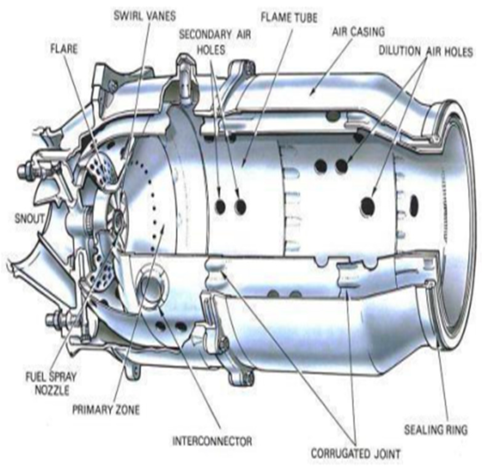
The air from the engine compressor reaches the combustion chamber at speeds of up to 500 feet per second, but because this is far too fast for combustion, the chamber must first disperse it, i.e., decelerate it and elevate its static pressure. Because the speed of burning kerosene is only a few feet per second at standard mixture ratios, any fuel burnt even in the dispersed air stream, which now has a velocity of around 80 feet per second, would be blasted away. An area of low axial velocity must thus be produced in the chamber so that the flame remains lit throughout. The ratio of a combustion chamber can range between 45:1 and 130:1. Kerosene, on the other hand, will only burn efficiently at or near a ratio of 15:1, therefore the fuel must be burned with only a portion of the air entering the chamber, in what is known as a main combustion zone. This is accomplished by the use of a flame tube (combustion liner) with various systems for metering the air flow distribution throughout the chamber. The snout or entering segment absorbs approximately 20% of the air mass flow.
Path of Air Flow Distribution
The primary air
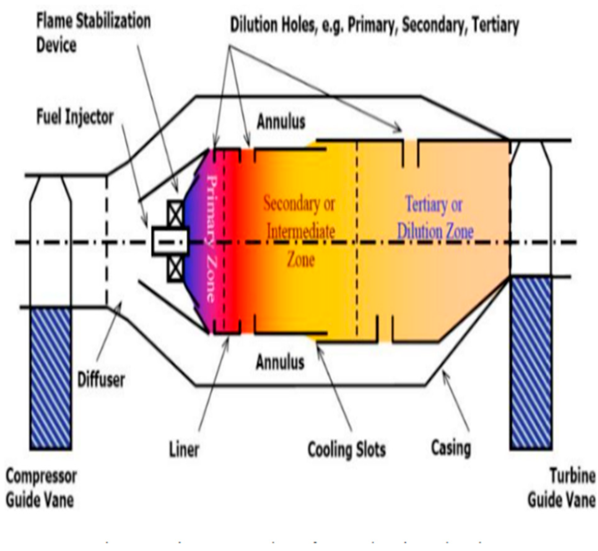
This is the principal source of combustion air. It is heavily compressed air from a high-pressure compressor (typically decelerated via a Diffuser). That is sucked via the main channels in the combustor dome and the first set of liner holes. This air is combined with fuel and then burned.
The air in the middle
The air vaccinated into the combustion zone through the second set of liner holes is known as intermediate air (primary air goes through the first set). This air completes the response processes by cooling it and diluting the high levels of carbon monoxide (CO) and hydrogen (H2). Dilution air is airflow injected through holes in the combustion chamber liner to help cool the air before it reaches the turbine stages. The air is utilized carefully to achieve the desired uniform temperature profile in the combustor. But, when turbine blade technology advances, allowing blades to withstand greater temperatures, dilution air is required less, allowing more combustion air to be used.
The rotating air creates a flow upstream of the flame tube's center, promoting the necessary recirculation. The air that the snout does not pick up flows into the annular space between the flame tube and the air casing. A number of secondary holes in the wall of the flame tube body, next to the combustion zone, allow an additional 20% of the main flow of air to enter the primary zone. The air from the swirl vanes interacts with the air from the secondary air holes, resulting in a zone of low velocity recirculation. This takes the appearance of a toroidal vortex, similar to a smoke ring, and serves to stabilize and anchor the flame (Figure 3). By swiftly bringing freshly injected fuel droplets to ignition temperature, the recirculating gases expedite their burning. It is set up so that the conical fuel spray from the nozzle intersects the recirculation vortex in the center. Along with the normal turbulence in the main zone, this action substantially aids in breaking up the fuel and mixing it with the entering air. The temperature of the gases generated by combustion is around 1,800 to 2,000 degrees Celsius, which is far too hot for passage into the turbine's nozzle guiding vanes. Cooling air can now enter a network of passageways within the flame tube wall before escaping to an insulating coating of air, according to a recent breakthrough. This can lower the amount of wall cooling airflow required by up to 50%. Otherwise, the incoming air will cool the flame and result in incomplete combustion if combustion is not completed before the diluting air enters the flame tube.
Relevant Contemporary Issue and Identification of Problem
Designing a combustion chamber that minimizes emissions of pollutants such as nitrogen oxides (NOx), carbon monoxide (CO), and particulate matter is a significant challenge. Striking a balance between combustion efficiency and low emissions requires careful design considerations. Continuous research and development efforts are dedicated to improving combustion chamber designs to enhance efficiency as well.
Literature Review/Background Study
- 1.
- A REVIEW OF THE LITERATURE ON CAN TYPE COMBUSTION CHAMBER
A Review on the Use of Computational Fluid Dynamics in Gas Turbine Combustor Analysis and its Scope, H. A. Bhimgade and S. K. Bhel. [1]
The CFD application and scope of this study are mostly focused on gas turbine combustor (usually can or tube, annular, and tub annular type of combustor utilized in gas turbines for improved efficiency). In many actual combustion applications, such as gas turbines and diesel engines, combustion occurs in a turbulent flow environment. Therefore, it is critical to represent the consequences of turbulence and mixing interactions, including all relevant physical and chemical processes. At the moment, the emphasis is on how turbulence causes enhanced mixing, which can then be used to compensate for inaccurate chemical reaction rate predictions. This, however, must be dealt with mathematically and physically. Both methods pertain to an incomplete mixing process that may cause the fuel vapour to ignite before the auto-ignition delay period or outside of the primary reaction zone. The mixing step physically accelerates the total reaction rate by extending and wrinkling the preheating zone. Nevertheless, turbulent spray combustion simulation remains a difficult task due to the high link that exists between the anticipated vapour mass fraction and the chemical process. The experimental results and semi-empirical correlations for calculating CO, UHC, NOx, exhaust gas temperature, and inner liner wall temperature as a function of different operating parameters are relevant for gas turbine combustor design, and further development of design is conceivable. Even with existing physical models, CFD can provide cost-effective solutions for a wide range of complex systems relevant to the power generation, aero-engine, and process industries.
- Dr. A.N. Pawar and Sachin Bhalerao. Thermal mapping of a can types gas turbine combustion chamber using CFD. [2]
This paper demonstrates that increasing the combustor exhaust temperature increases gas turbine efficiency. The simulation and results of the thermal flow behavior of the combustion chamber using CFD are discussed in this paper. A conventional can type combustion chamber serves as the combustor understudy. The whole length of the combustor, including the diffuser section at the outlet, is 567mm.
After a series of testing shown that further refinement in either direction had no significant effect on the velocity and scalar variables at any point in the combustor, a mesh of 557K nodes is constructed. 3 million complete tetrahedral volume cells are used to discretize the domain. A mesh generator generates the grids. To approximate the domain, 2-D quadrilateral grids are used.
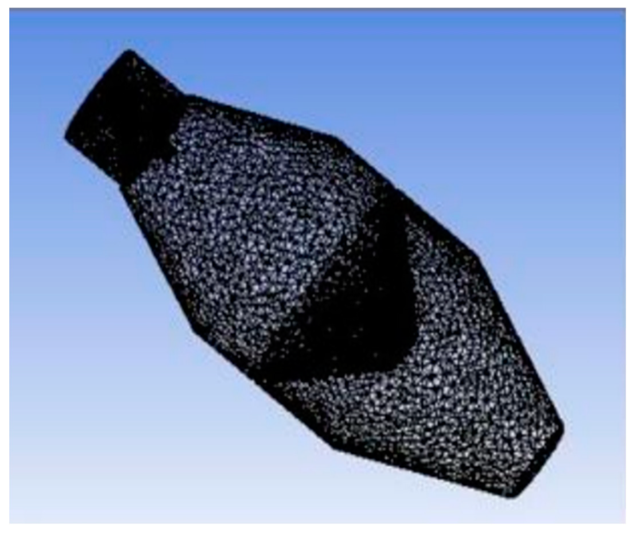
Figure 5.
Distinct Meshed Geometry Perspectives for a Combustion Chamber.
Graph 1.
Temperature Distribution Throughout the Combustion Chamber.
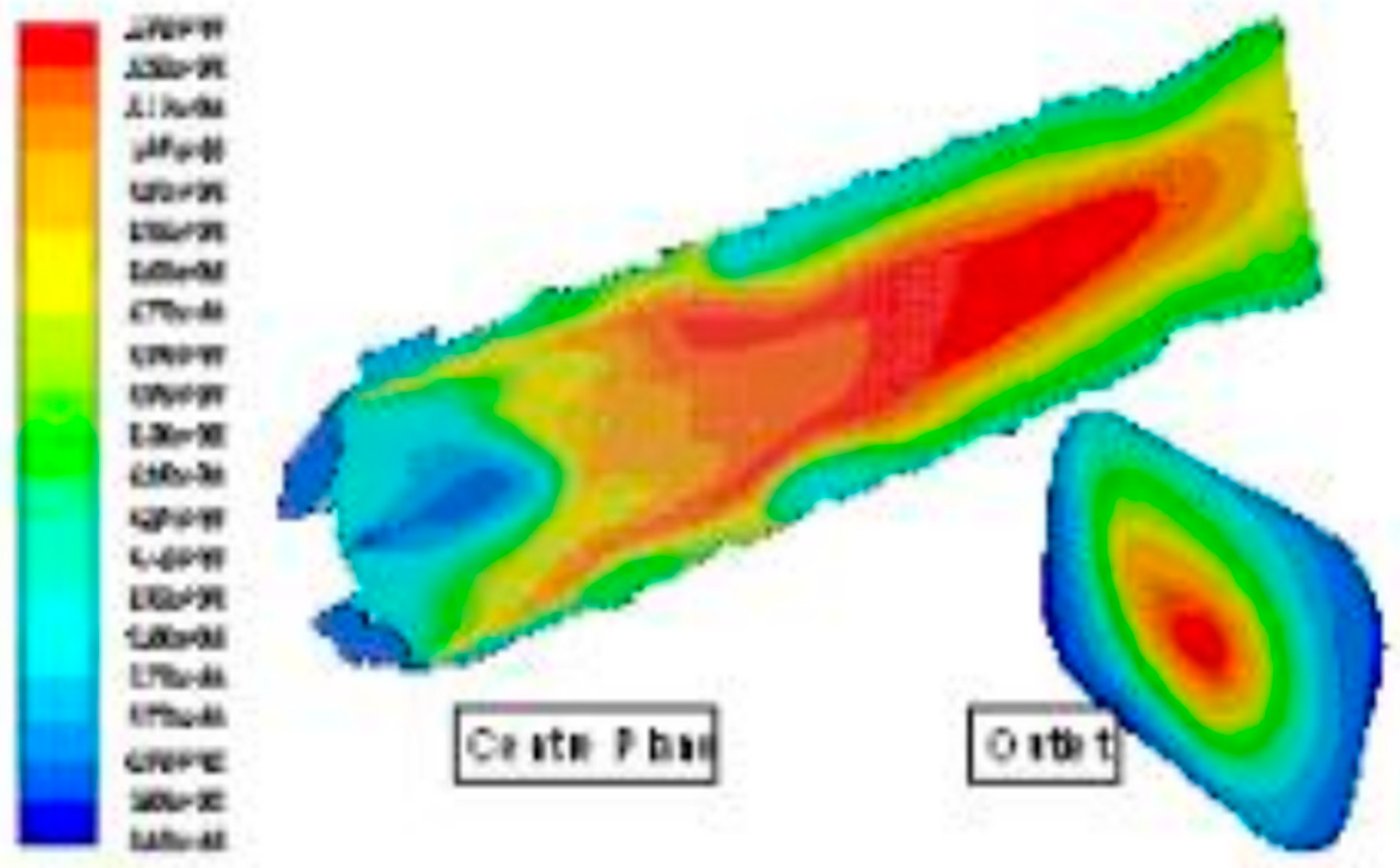
Man Young Kim and Selvakuma Kumaresh, “Combustion and Emission Properties in a Can-type Combustion Chamber." [3]
Several flow configurations with varying swirl angles are investigated in this study, and the motility of holes in the secondary chamber is varied to investigate the emission of unburned gases and to obtain an effective combustor with minimal NOx emission. Numerical analysis of a Can-type combustion chamber reveals that 60° swirl geometry produces less NO emission because the temperature at the combustion chamber's outlet is lower than 30° and 45° swirl angle geometry.
Figure 6.
Can Combustor Mesh Domain.
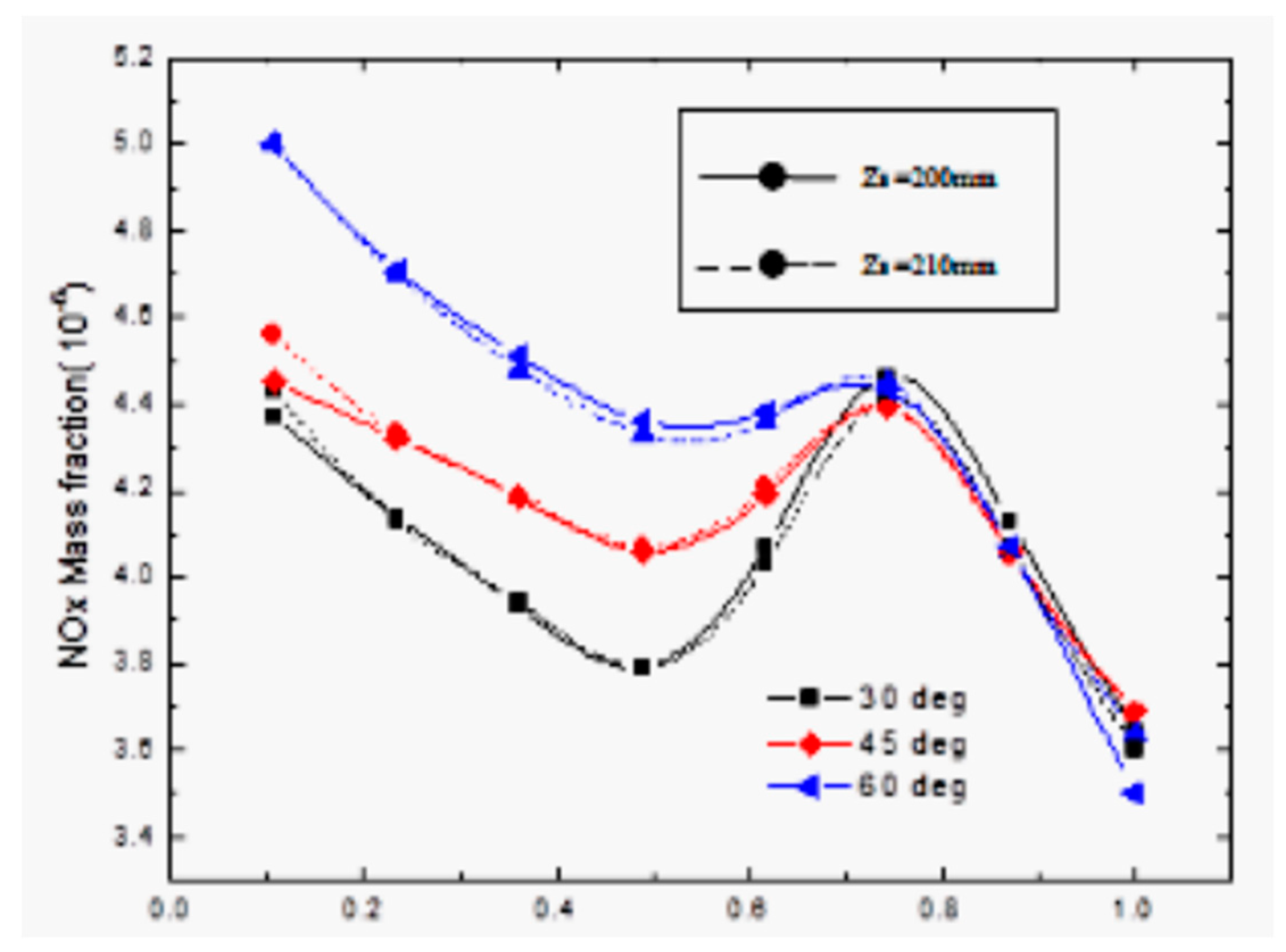
This study uses an algebraic grid-generation technique to discretize the geometry of a can combustor. The NOx mass fraction is shown at various swirl angles and axial distances. The primary chamber at Xs=0.7 decreases NOx emission due to air cooling. A 60-degree swirl angle at the secondary inlet site of 200mm achieves delayed emission and superior performance in aircraft applications. Parametric tests show that calculating NOx emissions helps create a low-emission combustor.
Design and Analysis of Gas Turbine Combustion Chamber, P. Sravan Kumar and P. Punna Rao. [4]
This study describes the design of a combustion chamber, which is followed by three-dimensional simulations to investigate the velocity profiles, species concentration, and temperature distribution within the chamber, utilising Methane as the fuel (CH4). The following findings are drawn from their analysis.
Figure 7.
NOx mass fraction variations for the can-combustor with varying swirl angles and axial distance.
Figure 7.
NOx mass fraction variations for the can-combustor with varying swirl angles and axial distance.
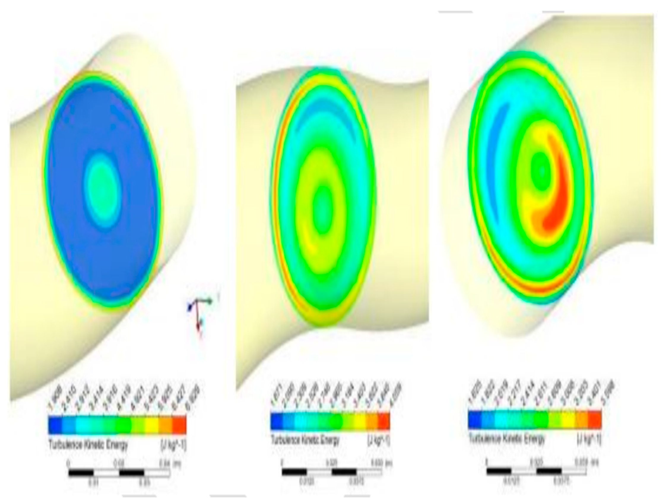
The static temperature is relatively high in the areas where combustion occurs and gradually decreases towards the outlet. The greatest temperature reached is 2500 K, indicating that the combustion process is efficient. The turbulence intensity is strong in the immediate area of the ramp injector, indicating that the air-fuel mixture is superior. A high turbulence intensity suggests excellent air-fuel mixing.
The quick increase in temperature near the injector tip shows the generation of shocks, which aid in enhanced air-fuel mixing. Better air-fuel mixing results in improved combustion quality and, as a result, improved performance.
Dr.G.Kalivarathan, P.S.Jeyalaxmi, CFD analysis of flow characteristics in a petrol turbine- A realistic approach to predicting turbulence. [5]
The RNG k- ε turbulence model employed in the examples is found to be practical in this inquiry, and the RSM model remarkably depicts the turbulence level and dilution jet mixing at the combustor outlet. Yet, it is easier to predict fluctuations in mean flow field results using CFD. As a result of these factors, further efforts must be made to test different turbulence models in order to obtain a more suitable means of anticipating this type of whirling, extremely turbulent, and flow scenario in a generic fashion using a feasible CFD tool.
CFD Modeling of Swirling Effect in S-Shaped Diffusing Duct by Swirl Angle of 10 Ramazan, Jawaz Pasha, Abdul Mujeeb M S. [6]
This work uses CFD to forecast the swirl effect on the properties of a constant, incompressible flow through an S-shaped diffusing duct with a swirl angle of 10 degrees. The curved diffuser in this example has an S-shaped diffusing duct with an area ratio of 1.9, a length of 300 mm, and a turning angle of 22.5 degrees.
The study reveals that static pressure recovery improves with swirl flow at the intake, regardless of direction (clockwise or anticlockwise), by about 40%. The flow distribution at the exit plane is more uniform for clockwise swirl compared to anti-clockwise swirl. Secondary flow is present throughout the diffuser, with a pair of vortices at each section. Swirl flow has only circular motion and strong turbulence intensity at the planes before and after the inflexion plane. The variance in turbulent intensity at the exit of clockwise swirl flow is lower than at the entrance.
II. A REVIEW OF THE LITERATURE ON TUBULAR TYPE COMBUSTION CHAMBER
Review on Research of expendable turbojet tubular combustion chamber Nikola S. Davidović, Nenad M. Kolarević, and Marko V. Miloš 2022 [7]
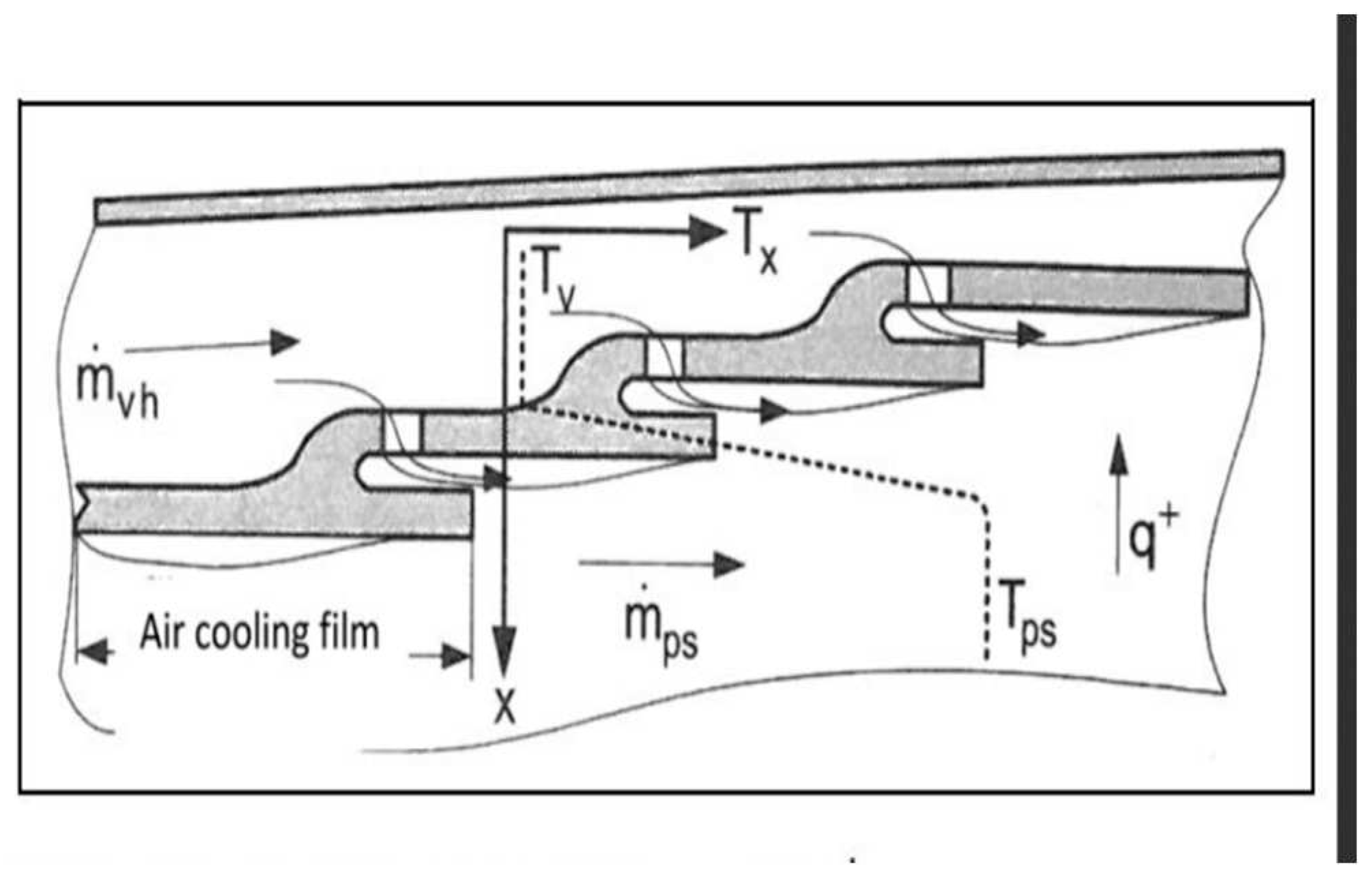
The paper has been completed its research on tubular combustion chamber. The reason being that they are easy to produce and require lower amount of air flow for testing. The test was completed under atmospheric conditions. Results obtained was wide enough to cover entire combustor working area.The power for turbine is obtained by mixing pressurized air from the compressor with the fuel to produce hot gases. Within the three zones the primary zone is in which the fuel to air mixture us maintained to achieve good stability and ignitability. It burns approx. 70% of fuel in this zone and the remaining should be finished within the secondary zone. The cooling system solution for this experiment as shown below:
Figure 8.
Cooling Solution Film Cooling.
The simplified design of combustion chamber is used without any modification. The tubular chamber was used to produce and test a single liner.
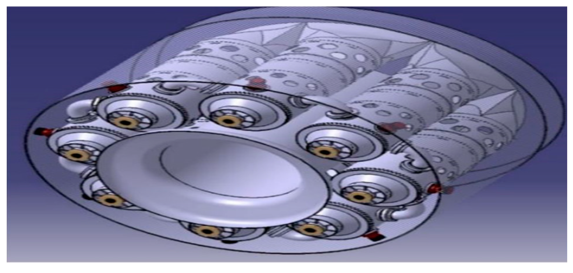
Figure 9.
Package for tubes after design process.
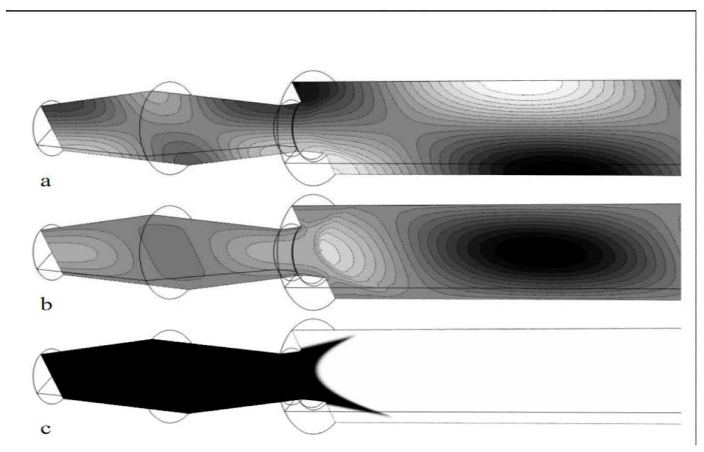
Review of Interaction of Vortex Shedding and Transverse High-Frequency Pressure Oscillations in a Tubular Combustion Chamber Schwing, J., Sattelmayer, T., & Noiray, N. (2011). [8]
This paper conducts the research on the thermoacoustic stability of premixed gas turbine combustor. All are experimental numerical based approaches to solve the problem of thermoacoustic instabilities on low frequencies. The perturbations of the shear layer are convectively unstable grow, roll up and form vortices.
Experiments was made in single burner test to maintain acoustic mode shapes cylindrical tube is used. To measure acoustic movements piezoelectric sensors are used. Optical techniques are used to get information on the flow field and on the turbulent flame.
Figure 10.
Acoustic pressure (a), y-component of the acoustic velocity (b) of a TI mode in combustor with temperature profile (c) in x-y-plane. Minimum is marked black, maximum white. Pressure and velocity are shifted by л/2.
Figure 10.
Acoustic pressure (a), y-component of the acoustic velocity (b) of a TI mode in combustor with temperature profile (c) in x-y-plane. Minimum is marked black, maximum white. Pressure and velocity are shifted by л/2.
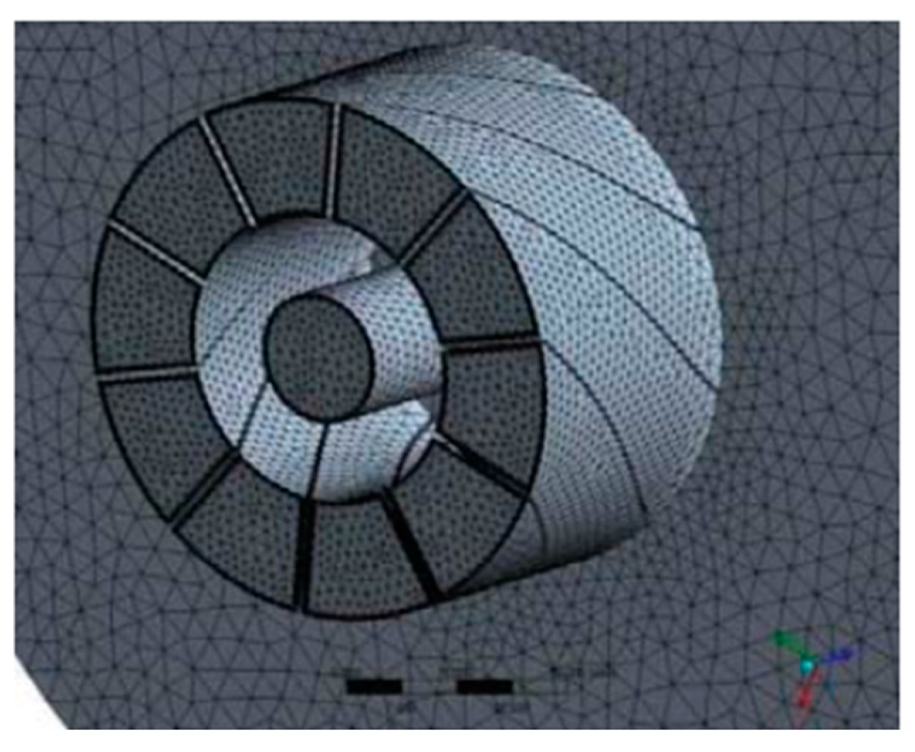
Review of Numerical simulation of combustion processes in a gas turbine. Bicsák, G., Hornyák, A., & Veress, A. (2012). [9]
The paper shows research in CAD systems which can help to reduce the high manufacturing cost of chambers and other parts
Figure 11.
The Inflation layer in the Vanes.
Review of Reference Area Investigation in a Gas Turbine Combustion chamber using CFD Fagner Luis Goular Dias, Marco Antonio Rosa do Nascimento, Lucilene de Oliveira Rodrigues 2014. [10]
It focuses on the issue of usage of Gas turbine engines for electrical power and their emissions due to it. The main motive has been to provide require modifications and preliminary design of reference area as the most important parameter through numerical investigation using Ansys CFX.
The dimension of the chamber is based on pressure losses corresponding to a design value. The tubular chamber sows pressure losses around 6-8%. Which are equally divided in 3 parts primary secondary and the ending dilution zone.
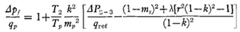
Review of Design of Tubuar Gas Turbine Combustion Chamber for Optimum Mixing Performance Lefebvre, A. H., & Norster, E. R. (1968). [11]
The paper focuses on the research of distribution of temperature in the efflux gases discharging into turbine. The optimum temperature is considered to be as 1800 K where the appropriate proportion of air flow occurs.
For maximum casing area a combustion zone of length /diameter ratio of 1:4 is taken. Most of the burning occurs in Primary region. Now changing optimum factor ‘k’ with the formula
We conclude that in tubular type combustion chamber the manufacturing and testing is simple and easy as compared to other types of combustion chambers. Drawbacks we can observe is that there are various efficiency lags due to vibrations and interaction of vortex shedding. If research and experiments is to be done in pre-mixed model of combustion chamber. Tubular type requires research and study in mixing of fuel which does not occur efficiently and there are various losses.
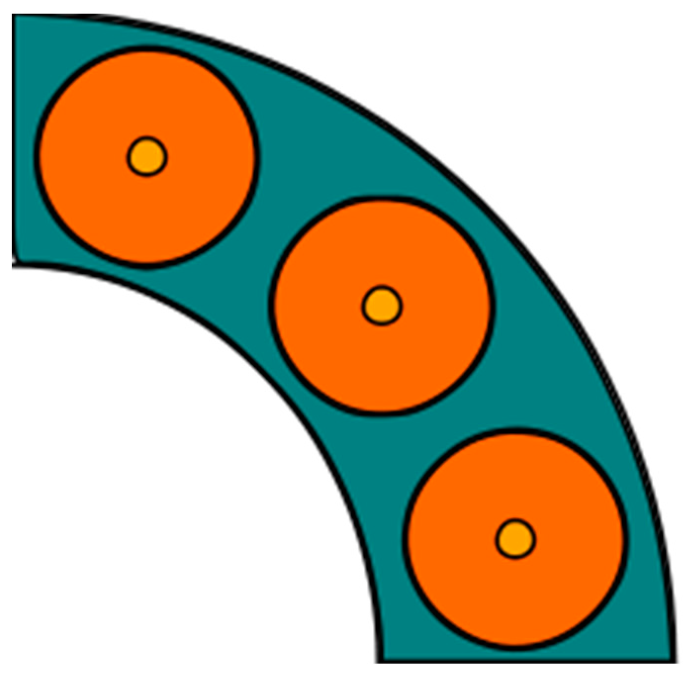
III. A REVIEW OF THE LITERATURE ON CAN-ANNULAR TYPE COMBUSTION CHAMBER
Can-annular combustors, similar to can-type combustors, consist of individual combustion zones that are enclosed in separate liners and equipped with their own fuel injectors. However, unlike can combustors, all the combustion zones of can-annular combustors are situated within a shared ring casing. Consequently, each combustion zone no longer needs to function as a pressure vessel
Figure 12.
Can-Annular combustor for a gas turbine engine, viewing axis on through the exhaust. Reference Image: https://en.wikipedia.org/wiki/File:CanAnnularCombustor.svg.
Figure 12.
Can-Annular combustor for a gas turbine engine, viewing axis on through the exhaust. Reference Image: https://en.wikipedia.org/wiki/File:CanAnnularCombustor.svg.
Thermoacoustic Properties of Can Annular Combustors, 8th AIAA/CEAS Aeroacoustics Conference, 4 Nov 2012. [12]
This paper conducts a thorough three-dimensional finite element analysis of a Can-Annular combustor design. Initially, the study focuses on a single Can setup and examines how the modes of acoustic pressure distribution are affected by the boundary condition at the plate's head.
Figure 13.
FE model of a can annular combustor.
Thermoacoustic of Can-Annular Combustors, ASME, September 14, 2018. [13]
In this paper, we are introduced with a low-order model for the acoustic communication at the turbine inlet between the transition ducts of can-annular combustors having N cans. The model is used to discuss the mode patterns and eigenfrequencies of can-annular combustors.
The research analyzes how the eigenfrequencies of can-annular systems change when the overall axial length of the cans is altered. It also forecasts the possibility of clusters of eigenmodes with very similar frequencies. Additionally, the study explores how a loss of rotational symmetry in the system causes mode localization.
Influence of rotational asymmetry on thermoacoustic instabilities in a can-annular lean-premixed combustor, Elsevier Inc. 19 October 2020. [14]
In this study, we expanded on the previous research by examining rotationally asymmetric conditions and found that the loss of rotational symmetry leads to various linear and nonlinear phenomena that were not previously observable. The experiment tends us to know six different interaction patterns, including two modes that were also present under rotationally symmetric conditions (alternating four-can push-pull and two-can push-pull modes) and four new types of interactions. The study scrutinized the behavior of these newly observed modes.
Design Flow/Process
Evaluation & Selection of Specifications/Features
- Selection of CAN- Type Combustion Chamber Over Other Types
- Simplicity: The design and the manufacturing process is relatively simple in case of Can-type combustion chambers, which can make them more cost-effective and consume less amount of time.
- Durability: Can-type combustion chambers are often made from durable materials, such as high temperature alloys, which can make them more resistant to heat.
- Combustion efficiency: Can-type combustion chambers are designed to give efficient combustion by ensuring that the fuel and air are well-mixed and evenly distributed throughout the chamber.
- Flexibility: Can-type combustion chambers can be adapted to a wide range of engine sizes and applications, which makes them a popular choice for many different types of engines.
Primary Features of Can- Type Combustion Chamber
- High temperature resistance: Can-type combustion chambers are made of materials that can withstand the high temperatures and pressures that occur during combustion process.
- Complete combustion: The efficient combustion occurs due to the arrangement of multiple combustion cans and as there are swirl vanes that help to mix the fuel and air before ignition wherein it ensures a complete combustion and reduces emissions.
- Pressure loss across the combustion chamber is relatively low.
- Can- type combustion chamber has wide range of reliable operation at all flight conditions.
- Can-type combustion chambers are a reliable and efficient means of achieving high-temperature combustion.
Design Constraints
Temperature: Gas turbine combustion chambers must be able to withstand high temperatures without melting or warping. Therefore, the materials used must be able to withstand temperatures of up to 2000°C or higher.
Pressure: Combustion chambers must be able to withstand high pressures caused by the combustion process. The chamber must be able to handle the pressure created by the burning fuel without leaking or rupturing.
Fuel type: The type of fuel used in the combustion process will dictate the design and operation of the combustion chamber. Different fuels have different combustion characteristics, so the chamber must be designed to work efficiently with the specific fuel being used.
Emissions regulations: There are strict regulations governing the emissions produced by gas turbine combustion chambers. The design must incorporate features that minimize emissions and meet local emissions regulations.
Maintenance: The combustion chamber must be designed to allow for easy maintenance and repair, as it will be subject to high temperatures and pressures over time, which can cause wear and damage.
Size and weight: The combustion chamber must be designed to fit within the overall dimensions of the gas turbine and be lightweight enough to not affect the performance of the turbine.
Combustion efficiency: The combustion chamber must be designed to achieve high combustion efficiency, which means that as much of the fuel as possible is burned to produce energy.
Analysis of Features and Finalization Subject to Constraints
- High temperature resistance: Can-type combustion chambers are made of materials that can withstand the high temperatures and pressures that occur during combustion process.
- Complete combustion: The efficient combustion occurs due to the arrangement of multiple combustion cans and as there are swirl vanes that help to mix the fuel and air before ignition wherein it ensures a complete combustion and reduces emissions.
- Pressure loss across the combustion chamber is relatively low.
- Can- type combustion chamber has wide range of reliable operation at all flight conditions.
- Can-type combustion chambers are a reliable and efficient means of achieving high-temperature combustion.
- Fuel injection system
- Airflow pattern
- Combustion zone geometry
- Cooling system
- Material selection
- Combustion control system
Design Selection 1:
Configuration [Not selected]
Figure 14.
CAD Model of CAN-Type.
Figure 15.
Internal View.
Dimension of Combustion Chamber
Figure 16.
2-D Design of Combustion Chamber.
DESIGN SELECTION 2
Configuration [Selected ]
Based on simulation Result
Figure 17.
CAN TYPE COMBUSTION CHAMBER.
Methodology
The approach we are using for this problem is Finite Element Method (FEM) which is a popular method for numerically solving differential equations arising in engineering and mathematical modeling, for which we are mainly focusing on the swirler analysis of the combustion chamber. And find its effects in primary secondary zone of combustion chamber. The effective swirler leads to more complete combustion and have a significant reduction in emissions. The nodes and elements of body are as tabulated below:

Table 1.
Nodes and Elements.
| S. N | Nodes | Elements |
|---|---|---|
| 1. | Total Nodes | 29783 |
| 2. | Total Elements | 16577 |
| 3. | Corner Nodes | 4818 |
| 4. | Mid nodes | 24965 |
| 5. | solid elements | 16577 |
Table 2.
Material properties use for the swirler.
| S. N | Properties | Description |
|---|---|---|
| 1. | Melting point | 2650 degrees Celsius |
| 2. | Density | 8.89 g/cm3 |
| 3. | Tensile strength | 690 to 783 MPa |
| 4. | Yield strength | 480 to 550 MPa |
| 5. | Hardness | 220 to 270 BHN |
| 6. | Corrosion resistance | Excellent resistance to a wide variety of chemicals. |
| 7. | Oxidation | good oxidation resistance up to 1100 degrees Celsius. |
| 8. | Weldability | Good weldability with conventional fusion welding techniques. |
| 9. | Machinability | Good machinability with conventional machining tools. |
| 10. | Cost | Relatively low cost compared to other high-temperature materials. |
Results Analysis and Validation
Meshing of Swirlers
Figure 18.
Mishing of Swirlers of Combustion Chamber.
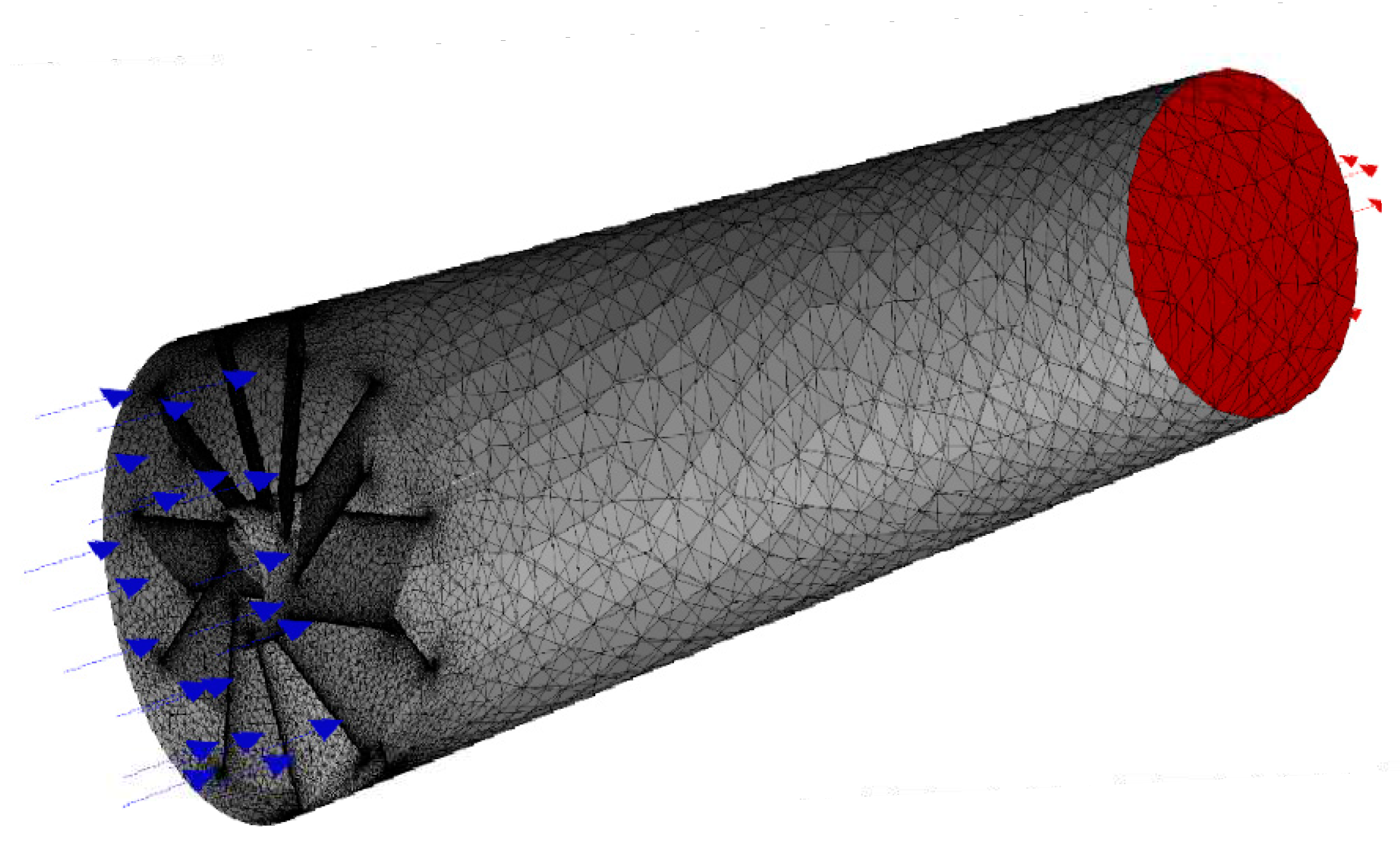
There are 29,783 nodes, 16,577 elements, 4,818 corner nodes, 24,965 mid nodes, and 16,577 solid elements in the mesh model. These components are utilised in the simulation to discretize the computational domain and represent the physical world. There are additionally 4,818 corner nodes, 24,965 mid nodes, and 16,577 solid components in the mesh model. With this degree of mesh resolution and complexity, simulation results may be thorough and precise for analysing the flow and thermal behaviour within the can-type combustion chamber.
Velocity Magnitude
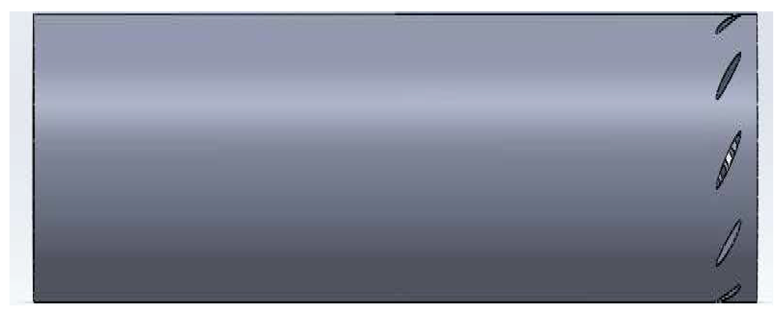
Figure 19.
Velocity Magnitude.
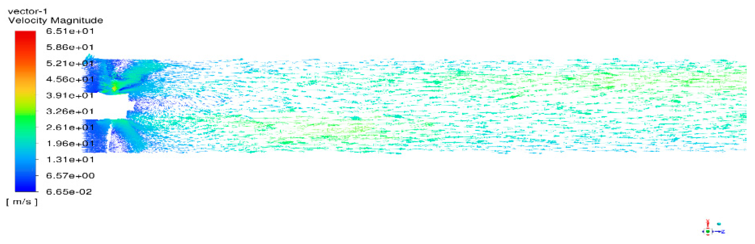
The range of the velocity magnitude lies from 6.65e-02 to 6.51e+01. But the average velocity if found to be followed everywhere i.e., at the intake of the swirler the velocity is 6.57e+00 and decreases further till 3.26e+01.
We found there are various points where air-fuel mixture starts to deflect from the path mostly at the outer edges due to the decrease in velocity.
Figure 20.
Mass fraction of CO / Emission of CO.
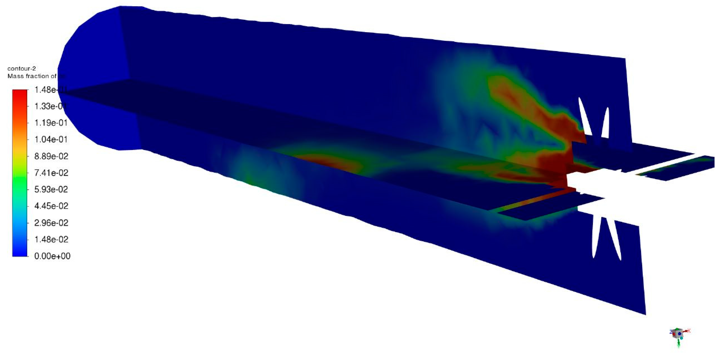
Emission of CO
The Figures shows the Mass fraction of Co contour 2 lies from 0.00e+00 to 1.48e-11.The mass fraction of CO is continuously decreased due to the combustion inside the combustion chamber.The blue coloured line depicts the CO that come from air inlet wit air.The concentration of CO is decreased due to large amount of heat is produced inside the combustion chamber.
Temperature distribution
Figure 21.
Temperature distribution.
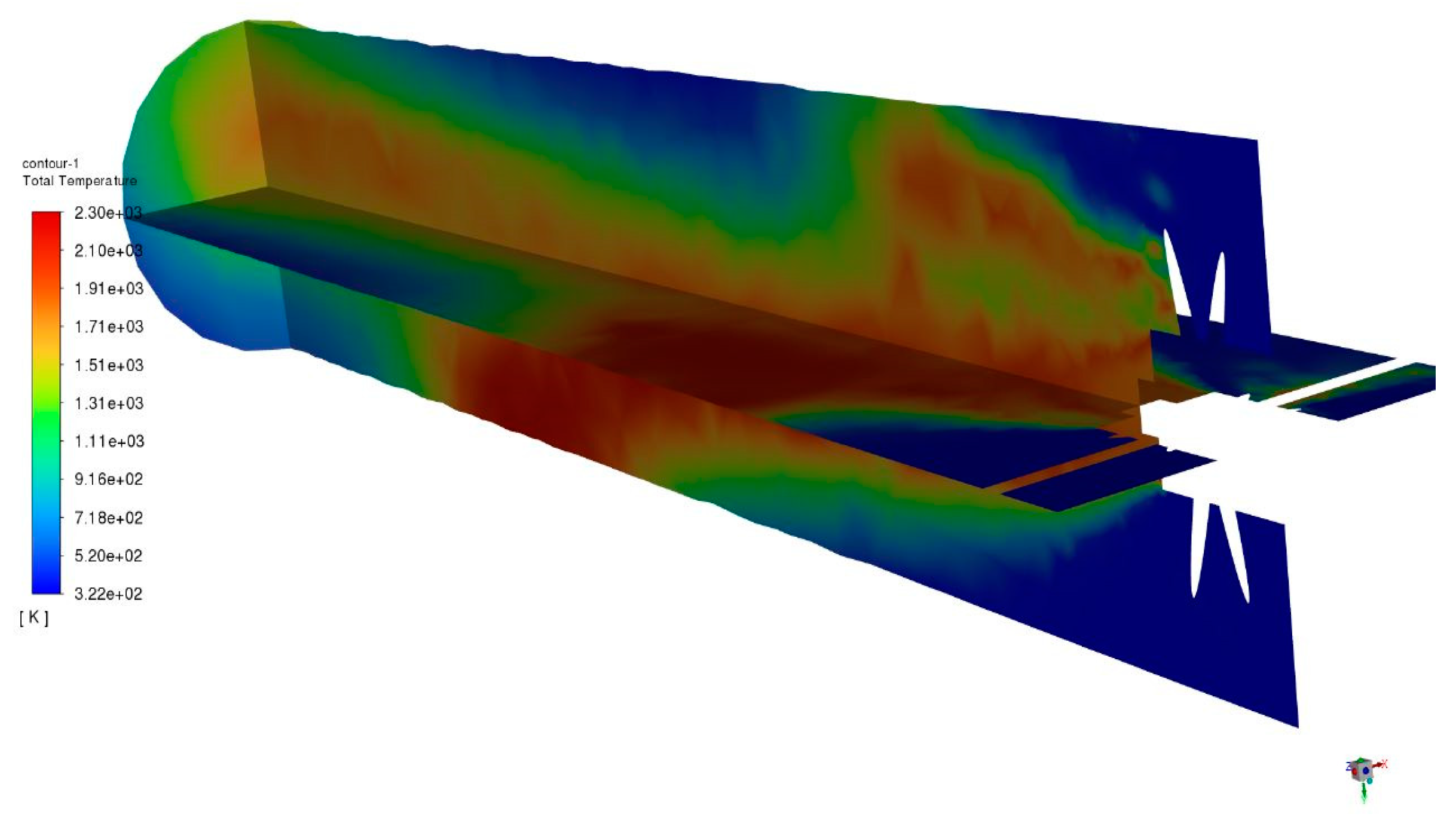
The figure explains about the Temperature variation inside the Can Type combustion chamber of gas turbine engine which ranges from 3.22e+02 to 2.30e+03. The blue colored indicates the air and the red color indicates the reaction of fuel with air inside the combustion chamber. The reaction of fuel with air produces large amount of heat inside the combustion chamber.
Turbulent Viscosity
Figure 22.
Turbulent Viscosity.
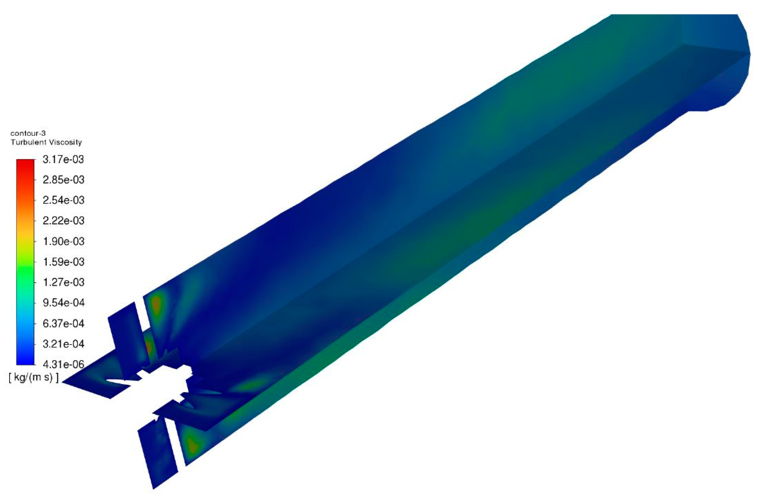
According to the ANSYS simulation results, the turbulent viscosity of the can-type combustion chamber ranges from 4.31e-06 to 3.17e-03 kg/ms. Turbulent viscosity is the measure of a fluid's resistance to flow induced by turbulence. It depicts the viscosity of the turbulent flow within the combustion chamber in this scenario.Turbulent flows have chaotic and uneven motion, and turbulent viscosity measures the strength of this turbulence. The ANSYS simulation's range of results reveals that the degree of turbulence within the combustion chamber can vary dramatically. A lower turbulent viscosity of 4.31e-06 kg/ms indicates a smoother, less chaotic flow with less resistance to motion. A higher number of 3.17e-03 kg/ms, on the other hand, suggests a more turbulent and chaotic flow with greater resistance to motion. Understanding and analysing turbulent viscosity in a combustion chamber is critical for optimising combustion processes, guaranteeing effective fuel-air mixing, and meeting performance objectives. These simulation findings may be used to fine-tune the combustion chamber's design and operating parameters for higher combustion efficiency and lower emissions.
Velocity Magnitude of Path lines
Figure 23.
Velocity Magnitude of Path lines.
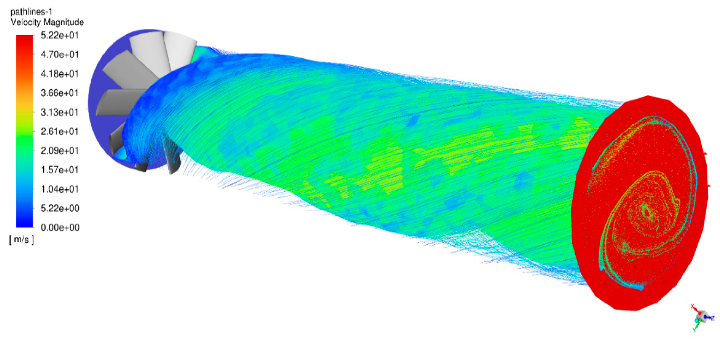
The velocity magnitude of pathlines in a can-type combustion chamber as simulated by ANSYS ranges from 0.00e-00 to 5.22e+01 m/s. The magnitude of the velocity indicates the speed of the fluid flow within the chamber. The measured data show a wide range of flow velocities, with some regions having very low or insignificant speeds near to 0 m/s and others experiencing comparatively higher velocities surpassing 52.2 m/s. These findings shed light on the flow dynamics within the combustion chamber and may be used to assess the combustion process's performance and efficiency.
Total Pressure vs Position
Graph 2.
Total Pressure vs Position.
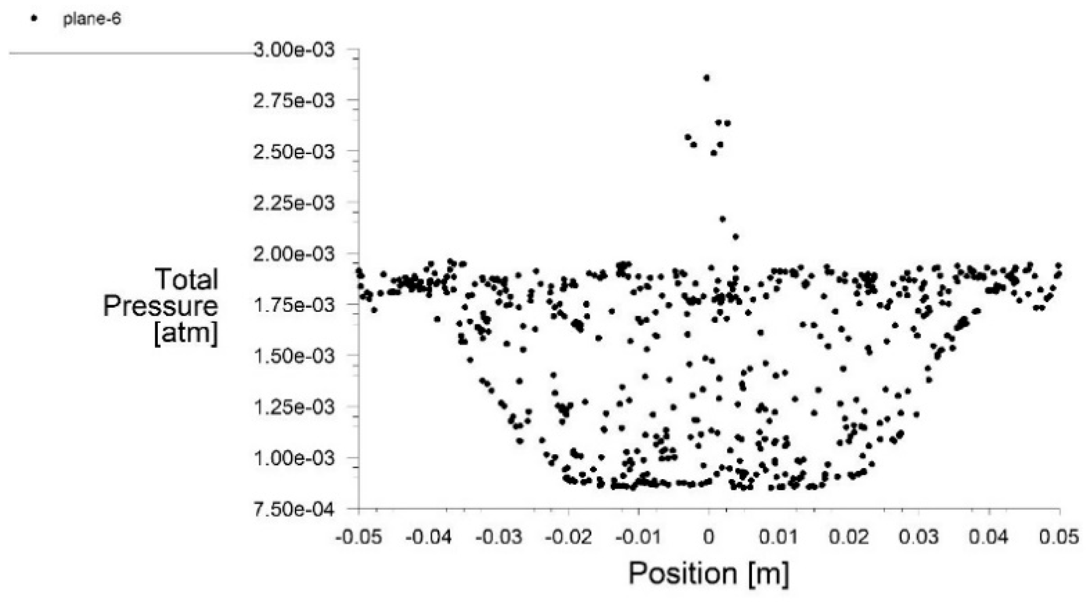
The total pressure versus position plot in a can-type combustion chamber displays the pressure distribution across the chamber at various points. Total pressure is the total of static and dynamic pressures, and it represents the fluid's energy content.
Total Temperature vs Position
Graph 3.
Total Temperature vs Position.
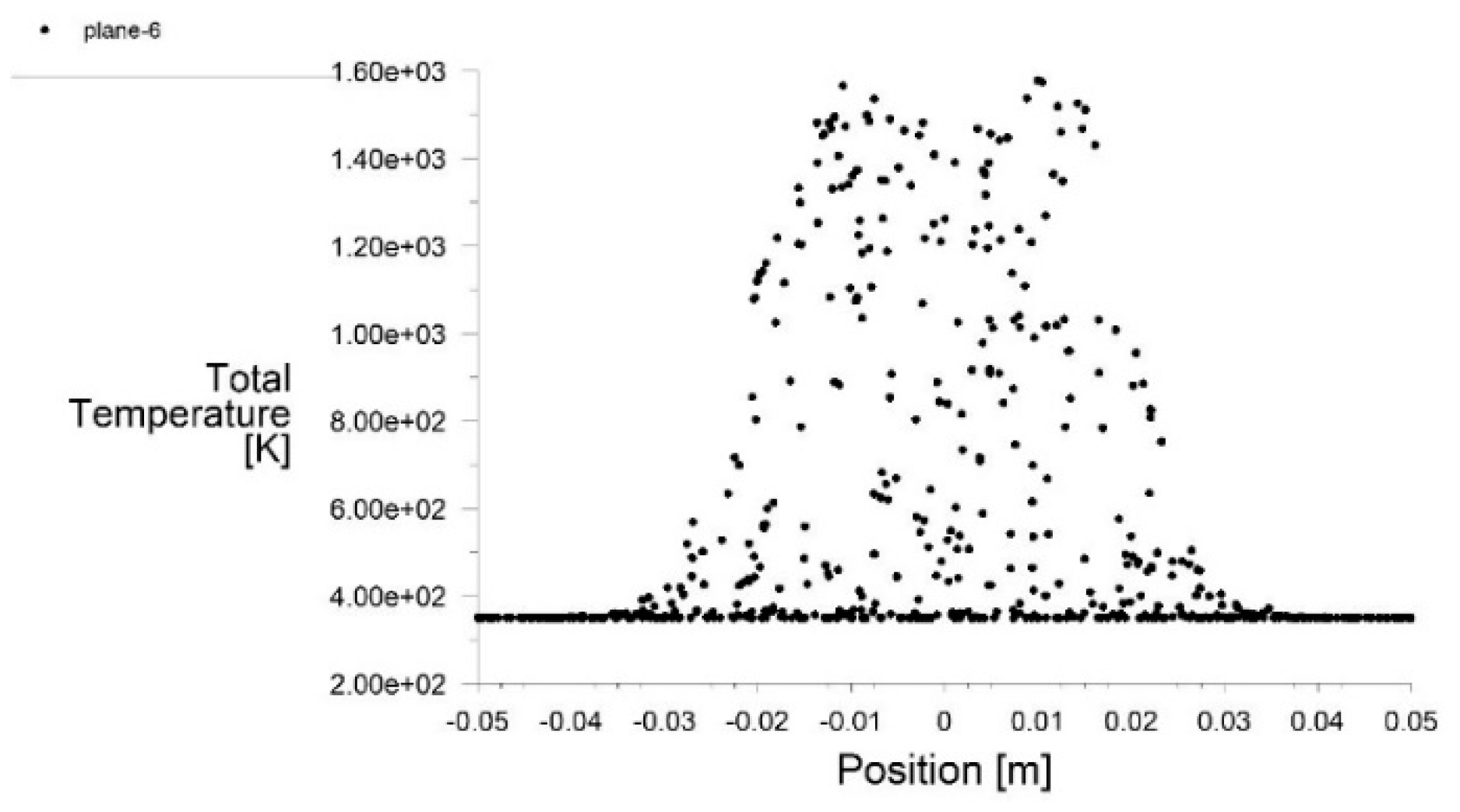
The total temperature versus position in a can-type combustion chamber displays the temperature distribution across the chamber at various places. The combination of static temperature and kinetic energy associated with fluid movement is referred to as total temperature. Temperature gradients, regions of high or low temperature, and possible locations of heat transfer or combustion inefficiencies can all be shown by the figure. It reveals information on fuel and air mixing and combustion, heat release patterns, and the thermal interaction of gases and combustion products within the chamber.
Cumulative Force vs Distance
Graph 4.
Cumulative Force vs Distance.
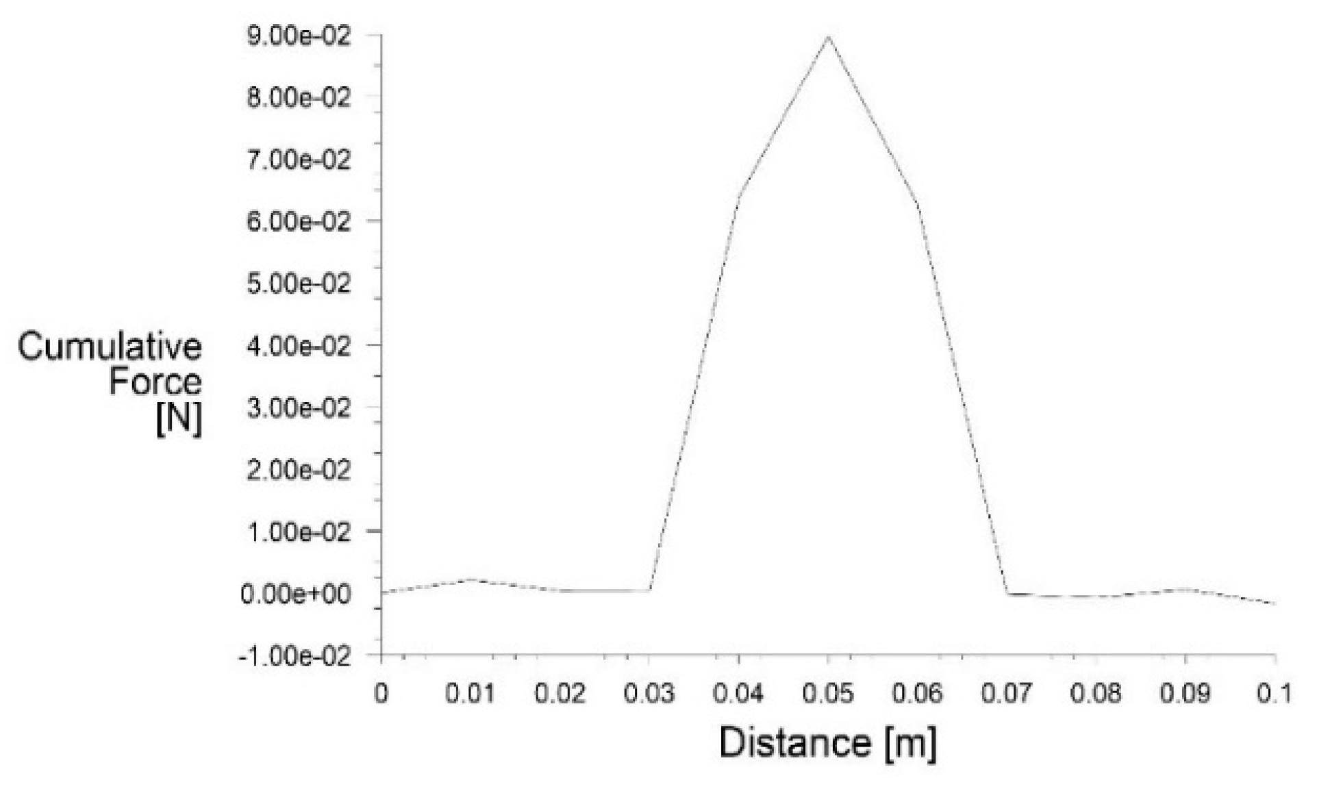
In a can-type combustion chamber, the cumulative force against distance is the overall force applied on a body or object within the chamber as a function of distance from a reference point. This data can give valuable insights into the mechanical behaviour of the chamber, such as areas of high or low force concentration, possible stress or strain regions, and structural integrity concerns. The cumulative force distribution analysis may help optimise the design and material selection for the combustion chamber, ensuring that components can sustain the forces applied on them without failure or excessive deformation.
Boundary Conditions:
Table 3.
Air Inlet Zone.
| Reference Frame | Absolute |
| Mass Flow Specification Method | Mass Flow Rate |
| Mass Flow Rate[kg/s] | 0.05 |
| Supersonic/Initial Gauge Pressure[atm] | 0 |
| Direction Specification Method | Normal to Boundary |
Table 4.
Turbulence.
| Specification Method | K and Elipson |
| Turbulent Kinetic Energy[m2/s2] | 1 |
| Turbulent Dissipation Rate[m3/s2] | 1 |
Equations
The chamber volume is typically determined based on the desired thrust or power output and the specific impulse or efficiency of the engine.
V = (Thrust or Power) / (Pressure × Specific Impulse)
- 1.
- Chamber Length:
The chamber length is typically determined based on the desired residence time of the combustion gases.
L = Residence Time × Average Combustion Gas Velocity
- 2.
- Chamber Diameter:
Diameter is determined by using a throat area based on the desired mass flow rate and combustion chamber pressure.
D = Throat Area = (Mass Flow Rate) / (Chamber Pressure)
Chamber Diameter = √(4 × Throat Area / π)
- 3.
- Swirler Area:Swirler Area = π × (swirler diameter/2)^2
- 4.
-
Adjusted Swirler Area = Swirler Area × ηEfficiency Factor - ηThe efficiency factor typically ranges from 0 to 1
- 5.
- Nozzle AreaNozzle Area = (Mass Flow Rate) / (Exit Velocity × Chamber Pressure)
Conclusion and Future Work
After analyzing and understanding all the above literatures, we can conclude that by optimization we can increase the combustion efficiency for a can type combustion chamber. Using CFD simulation, the effective design for such type of combustion chamber can be developed. After making some of the design modifications, we can minimize the pressure loss and can maximize heat release for limited space available. Using some of the experimental results and the semi empirical correlations for calculating CO, UHC, NO, exhaust gas temperature, inner liner wall temperatures, etc. developments in the design for a can type combustion chamber is possible. Such design modifications can offer cost-effective solutions for many complex systems of interest to the power generation, aero-engines and process industries.
References
- A Review on the Use of Computational Fluid Dynamics in Gas Turbine Combustor Analysis and its Scope, H. A. Bhimgade and S. K. Bhele., International Journal of Science and Research (IJSR), India Online ISSN: 2319-7064.
- Dr. A.N. Pawar and Sachin Bhalerao. Thermal mapping of a can types gas turbine combustion chamber using CFD, International Journal of Emerging trends in Engineering and Development. Vol.1 ISSN 2249-6149 Issue2.
- Man Young Kim and Selvakuma Kumaresh, "Combustion and Emission Properties in a Can-type Combustion Chamber.", Vol:8 No:7/2014, International Journal of Mechanical, Aerospace, Industrial, and Mechatronics Engineering. [CrossRef]
- Design and Analysis of Gas Turbine Combustion Chamber, P. Sravan Kumar and P. Punna Rao, Vol. 03, Issue 12/2013, International Journal of Computational Engineering Research.
- Dr.G.Kalivarathan, P.S.Jeyalaxmi, CFD analysis of flow characteristics in a petrol turbine- A realistic approach to predicting turbulence, ISSN 0976, Volume 4, Issue 2, March - April 2013. International Journal of Mechanical Engineering and Technology (IJMET).
- CFD Modeling of Swirling Effect in S-Shaped Diffusing Duct by Swirl Angle of 10 Ramazan, Jawaz Pasha, Abdul Mujeeb M S., ISSN: 2320-334X, IOSR Journal of Mechanical and Civil Engineering, Volume 6, Issue 2, March - April 2013.
- Expendable turbojet tubular combustion chamber Nikola S. Davidović, Nenad M. Kolarević, and Marko V. Miloš 2022.
- Interaction of Vortex Shedding and Transverse High-Frequency Pressure Oscillations in a Tubular Combustion Chamber Schwing, J., Sattelmayer, T., & Noiray, N. (2011).
- Numerical simulation of combustion processes in a gas turbine. Bicsák, G., Hornyák, A., & Veress, A. (2012).
- Reference Area Investigation in a Gas Turbine Combustion chamber using CFD Fagner Luis Goular Dias, Marco Antonio Rosa do Nascimento, Lucilene de Oliveira Rodrigues (2014).
- Design of Tubularr Gas Turbine Combustion Chamber for Optimum Mixing Performance Lefebvre, A. H., & Norster, E. R. (1968).
- Thermoacoustic Properties of Can Annular Combustors, 8th AIAA/CEAS Aeroacoustics Conference, 4 Nov 2012.
- Thermoacoustics of Can-Annular Combustors, ASME, September 14, 2018.
- Influence of rotational asymmetry on thermoacoustic instabilities in a can-annular lean-premixed combustor, Elsevier Inc. 19 October 2020.
- Cohen, H., Rogers, G. F. C., & Saravanamuttoo, H. I. H. (2007). Gas Turbine Theory (6th ed.). Pearson Education Limited. Chapter 7: Combustion Chambers.
- Oyekunle, L. O., & Ismail, I. M. (2018). A Review of Annular Combustion Chamber for Small Gas Turbine Engine. International Journal of Engineering Trends and Technology, 62(5), 272-277.
Figure 3.
Airflow Distribution.
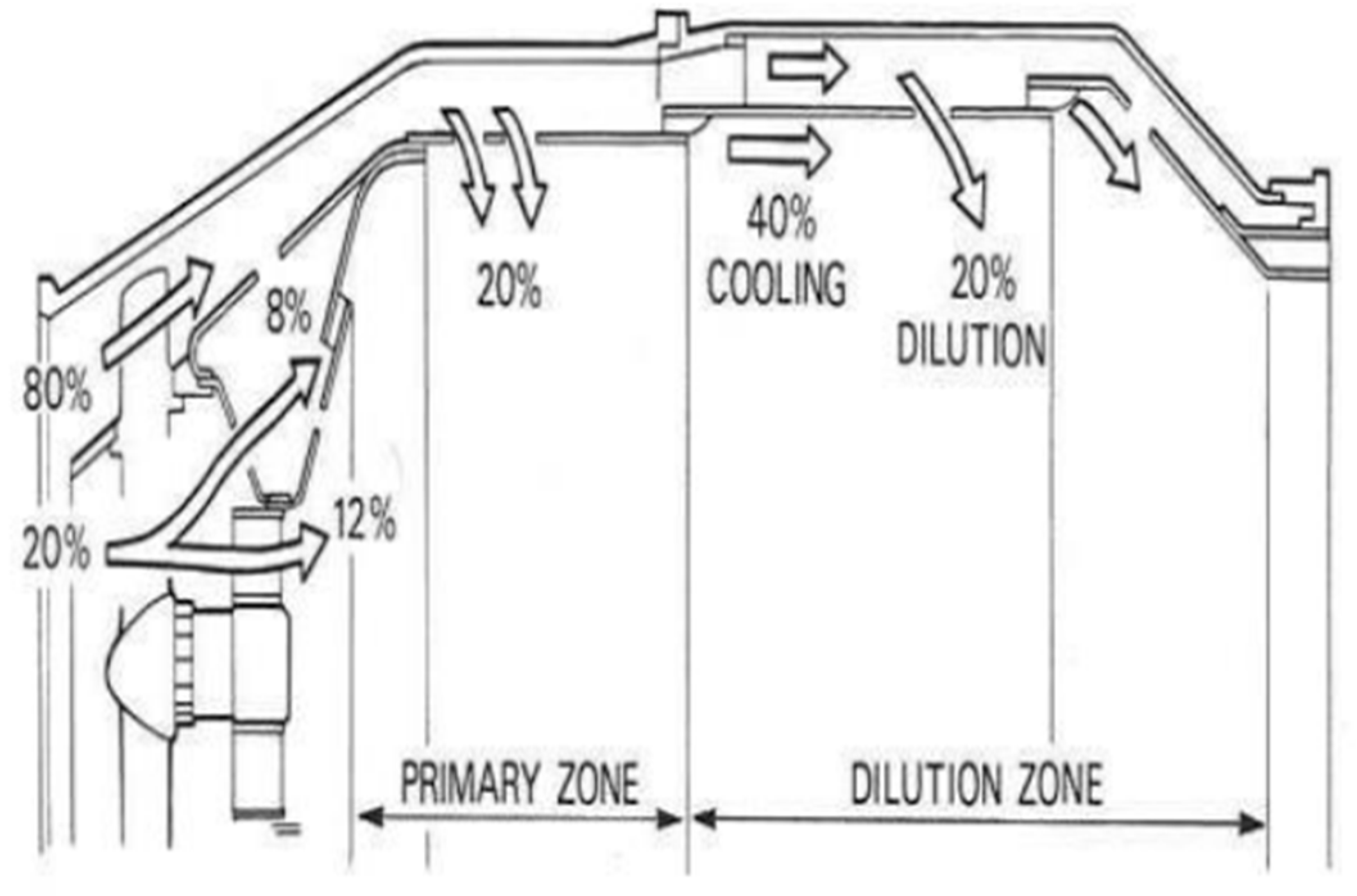
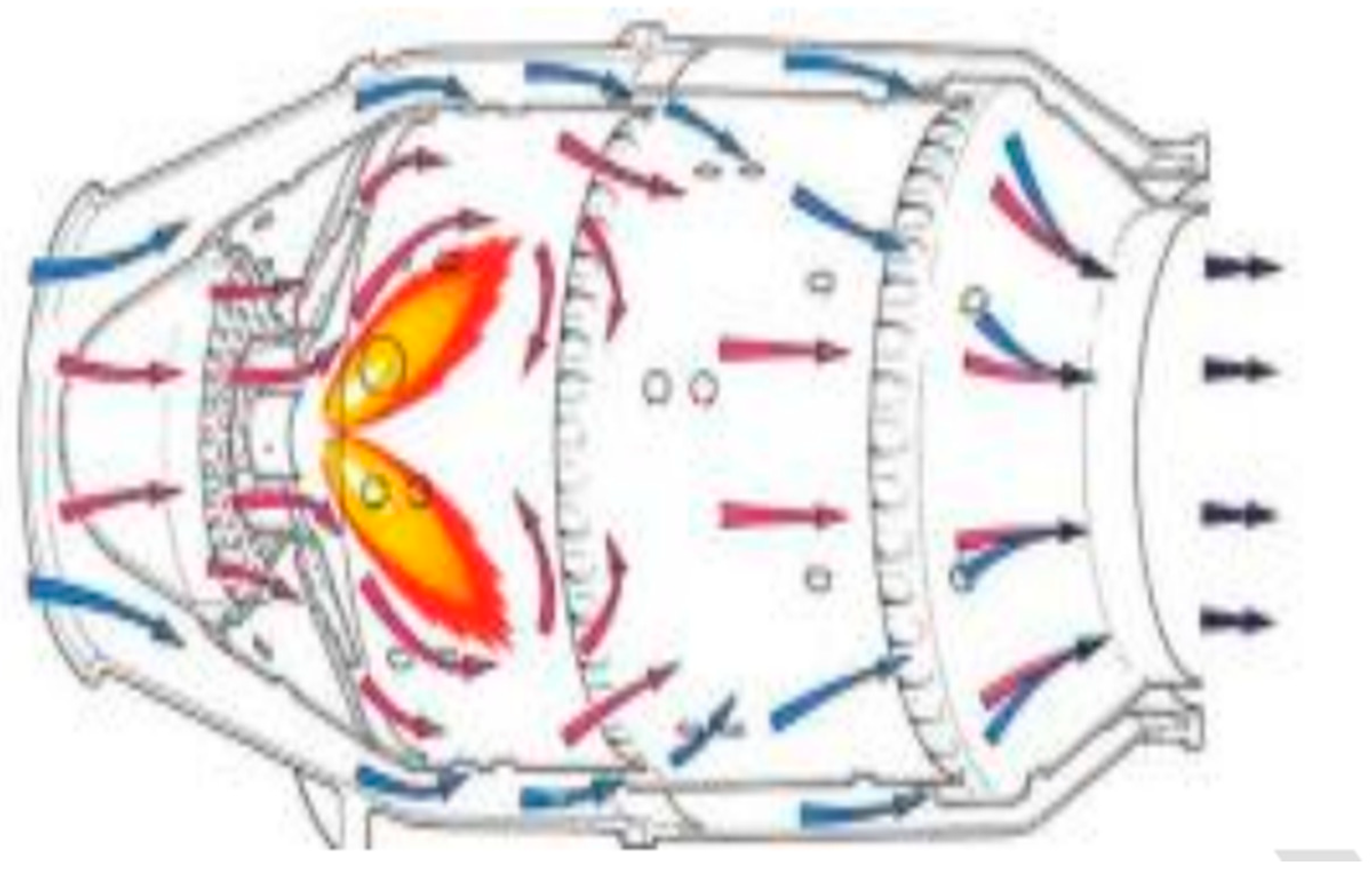
Figure 4.
Smoke Rings in the Combustion Chamber.
Disclaimer/Publisher’s Note: The statements, opinions and data contained in all publications are solely those of the individual author(s) and contributor(s) and not of MDPI and/or the editor(s). MDPI and/or the editor(s) disclaim responsibility for any injury to people or property resulting from any ideas, methods, instructions or products referred to in the content. |
© 2023 by the authors. Licensee MDPI, Basel, Switzerland. This article is an open access article distributed under the terms and conditions of the Creative Commons Attribution (CC BY) license (http://creativecommons.org/licenses/by/4.0/).
Copyright: This open access article is published under a Creative Commons CC BY 4.0 license, which permit the free download, distribution, and reuse, provided that the author and preprint are cited in any reuse.


