Introduction
Natural nitrate levels in groundwater are generally very low (typically less than 10 mg/L ), but nitrate concentrations are increasing due to human activities such as agriculture, industry, effluents household and emissions from combustion engines.
Nitrates generally leach relatively slowly into soil and groundwater: there is a lag period of about 20 years between polluting activity and detection of the pollutant in groundwater. For this reason, current activities are expected to continue to contribute to nitrate pollution for many decades. However, if the pressure in the aquifer is high, transport can be very rapid in the saturation zone. Nitrate concentrations are variable, especially in extreme climatic conditions.
Although the law in the European Union allows a maximum nitrate limit of 50 mg/L, doctors around the world find this figure far too permissive. They consider the value far too high, being a risk especially for infants and young children. Their recommendation is a maximum of 10 mg nitrates () per liter of water for water intended for the preparation of food for infants and young children (Yinhai, 2018).
The harmful effects of nitrates on human health and ecology have led to intensive research into cost-effective and efficient nitrate removal techniques. Consequently, numerous methods of nitrate removal have been developed.
In order to efficiently purify the water body and reduce the occurrence of eutrophication, phosphate recovery or removal have been developed so far.
There are several methods of nitrate removal, various separation techniques, including physical (Cataldo et al., 2016), chemical (Crutchik et al., 2013) and biological (Quartaroli et al., 2019) methods. For example, reverse osmosis is used, with the help of ion exchangers, electrolysis, chemical and biological denitrification and adsorption processes. (Panagopoulos, 2021c)
Among these methods, many have drawbacks, related to increased energy consumption, increased maintenance costs, preliminary removal of hardness and also, in cold periods, for biological methods, the efficiency is low.
However, adsorption is considered to be the most promising method among them for nitrate removal due to its ease of operation, high efficiency and remarkable degradation capacity to remove nitrates (Fulazzaky et al., 2014). The essence of adsorption is the physical and/or chemical interaction between the surface of the solid adsorbent and the target pollutant.
Permeable reactive barriers are some of the most promising technologies for passive groundwater treatment, due to the efficiency of retaining different contaminants, and the low price compared to other in situ technologies. The most economical and simplest method for removing nutrients from wastewater is based on the use of metals in the form of nanoparticles in combination with ion exchangers.
Nanoscale zero-valent iron (nZVI) has been extensively studied for the remediation of polluted aquifers, this being effective in reducing nitrates in contaminated areas. However, zerovalent iron nanoparticles are prone to agglomeration, this leads to a reduction of the specific surface area as well as a reduction in performance. In some cases, the release of nanoparticles into the environment can result in nanotoxicity, so it is recommended to stabilize them by incorporating them into support materials.
The use of nZVI for remediation of contaminated groundwater or wastewater is limited due to lack of stability, easy aggregation and difficulty in separating nZVI from the treated solution (Chekli, 2016), (Hwang, 2011). To solve these problems, nZVI was embedded in solid porous materials such as resin, betonite, zeolites trying to remove different contaminants. The use of a support can expand the application area by preventing nZVI agglomeration (Zhenmao, 2011).
The use of polymers containing quaternary ammonium groups as a support for nZVI confers some advantages: the uncharged functional groups allow anionic and cationic contaminants to enter into the polymer phase, the ferric ion can be strongly chelated by the nitrogen-containing pyridine groups as donor atoms, therefore, a high content of immobilized nZVI can be achieved and the release of iron ions into water can be avoided or ameliorated due to the strong chelating properties of the functional groups.
Sizing and design of BRP - The projection of permeable reactive barriers must correspond to the characteristics of the contaminated areas, the problems that may arise in the removal of contaminants must be taken into account. The thickness of the reactive layer along the barrier is adjusted for high concentration and for the contaminant that has a longer residence time (USEPA, 1998).
The use of a thick wall throughout the system also includes the placement of reactive cells that result in a varied ratio of reactive medium to inert materials for walls mixed with gravel, sand or other non-reactive materials. For an effective homogenization, it is necessary to cover the ascending part of the reactive cell with gravel. (Gavaskar et al., 1998).
The measurement of hydraulic conductivity can vary greatly depending on the area of contamination, so to design the correct thickness of the reactive area and to ensure safety, a very high conductivity must be used. Sizing for hydraulic systems is therefore the most important design aspect in the design of permeable reactive barriers.
Due to the fact that the barriers are heterogeneous a safety factor must be included when sizing the reactive cell so that the changes are taken into account.
Several sources recommend that the permeability of the reactive medium be ten times higher than that of the aquifer because unexpected situations such as sedimentation of fine particles and solid precipitation can occur that can reduce permeability. (NATO, 1998). If the permeability of the medium is greater than that of the aquifer, it will cause water to flow faster through the reactive medium than normal.
For in-situ applications, nZVI can be injected directly into contaminated sites in the form of sludge/suspension or introduced into the composition of permeable reactive barriers (PRBS). In a PRB structure, groundwater flows passively through an engineered nZVI wall while contaminants are precipitated, adsorbed, or transformed into non-polluting compounds (Thiruvenkatachari, 2008). Alternatively, nZVI can also be used in ex situ applications after its incorporation into a support material (solid support material) or hybrid. In addition, methods to separate nZVI particles from contaminated areas are still difficult and economically unfavorable. Incorporating nZVI into large solid particles could improve its easy separation from the aqueous system. Widely used supports for nZVI incorporation include granular activated carbon, resins and zeolite (Zhenmao, 2012), (Sliman, 2016).
In this study, nZVI was doped on an anion exchange resin (Purolite A400 is a strongly basic anion exchange resin, polystyrene-divinylbenzene gel type, with quaternary ammonium functional groups, in chlorine form) and the resulting material was tested for the removal of nitrates in a dynamic regime.
2. Materials and Methods
2.1. Materials
Purolite A400 (strongly base anion resin with gel polystyrene crosslinked with divinylbenzene structure, constating of quaternary ammonium functional groups, Cl- form) was purchased from Purolite Ltd (Purolite S.R.L., Bucharest, Romania an affiliate of Purolite Corporation, Pennsylvania, U.S.A). Ferrous sulfate hexahydrate (FeSO4·6H2O) and sodium borohydride (NaBH4) were acquired from Chimopar (Chimopar TRADING SRL, Bucharest, Romania). Ethanol (C2H5OH) and sulfuric acid (H2SO4) were purchased from Sigma Aldrich (Merck KGaA, Darmstadt, Germany). All the chemichal compounds were analytical grade and were used as procured. Distilled water was necessary for obtaining aqueous solutions.
2.2. Synthesis of the polymeric material
For the synthesis of the material, A400-nZVI, the anion exchanger A400 (
Figure 1) was used as a support material in which zero nanovalent iron particles were immobilized in two steps.
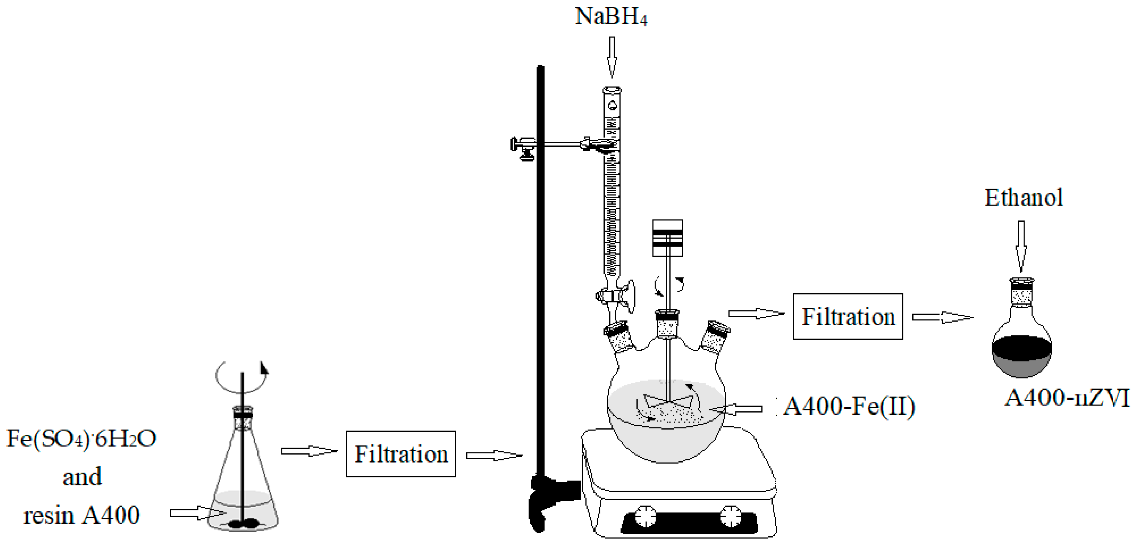
First, Fe2+ ions were incorporated into the porous support by adsorption and/or ion exchange at the respective functional groups of the porous support. Then, the adsorbed Fe2+ ions were reduced to Fe0 by exposing the porous support material to the NaBH4 solution.
The polystyrenic gel (Purolite A400) containing zerovalent iron nanoparticles (nZVI) was obtained as follows: 45 g of Purolite A400 was added to 250 mL of FeSO
4·6H
2O (0.2 M). After 3 h rotation in an end-over-end shaker, at room temperature (24 ± 1.0°C) under nitrogen atmosphere using a nitrogen gas bottle (BOC Linde Company
, Distribution Linde Romania, Bucharest), the obtained solution was filtered to separate the solid granules. The obtained solid granules were dried in the oven, under vacuum condition (MultiLab ML-LE 15/11, Distribution Laboratory and Analytical Equipment MultiLab Romania, Bucharest; IKA-Werke, Inc., Laboratory Equipment, Deutscland, Germany) at 30°C for 6 hours. After the obtaining stage, a quantity of 250 mL of NaBH
4 solution, with a concentration of 0.4 M, was prepared. This solution was introduced into a burette to which a round flask with three necks was connected, in which the dried granules was already added. The mixture was stirred using an end-over-end shaker for 3 hours, under a N
2 atmosphere. The obtained mixture was kept at room temperature (24 ± 1.0°C) for 3 hours. The borohydride reduction of the ferrous ions is described by the following reaction [22–24]:
The zero nanovalent iron anion exchange resin (A400-nZVI) was obtained through filtration and washed three times using deoxygenated water, and then stored in a round-bottomed flask over where was added ethanol solution (absolute for analysis), to prevent any further oxidation.
The schematic preparation of A400-nZVI was illustrated in
Figure 1.
For the dynamic study, the anion exchange resin impregnated with internally dispersed nZVI was drained, washed, and immediately used as a permeable reactive barrier.
2.3. Procedure
The dynamic study
A solution of potassium nitrate (KNO3), with a concentration of 100 mg/L, is used as the aqueous phase, the flow being kept uniform at three flow rates throughout the experiments.
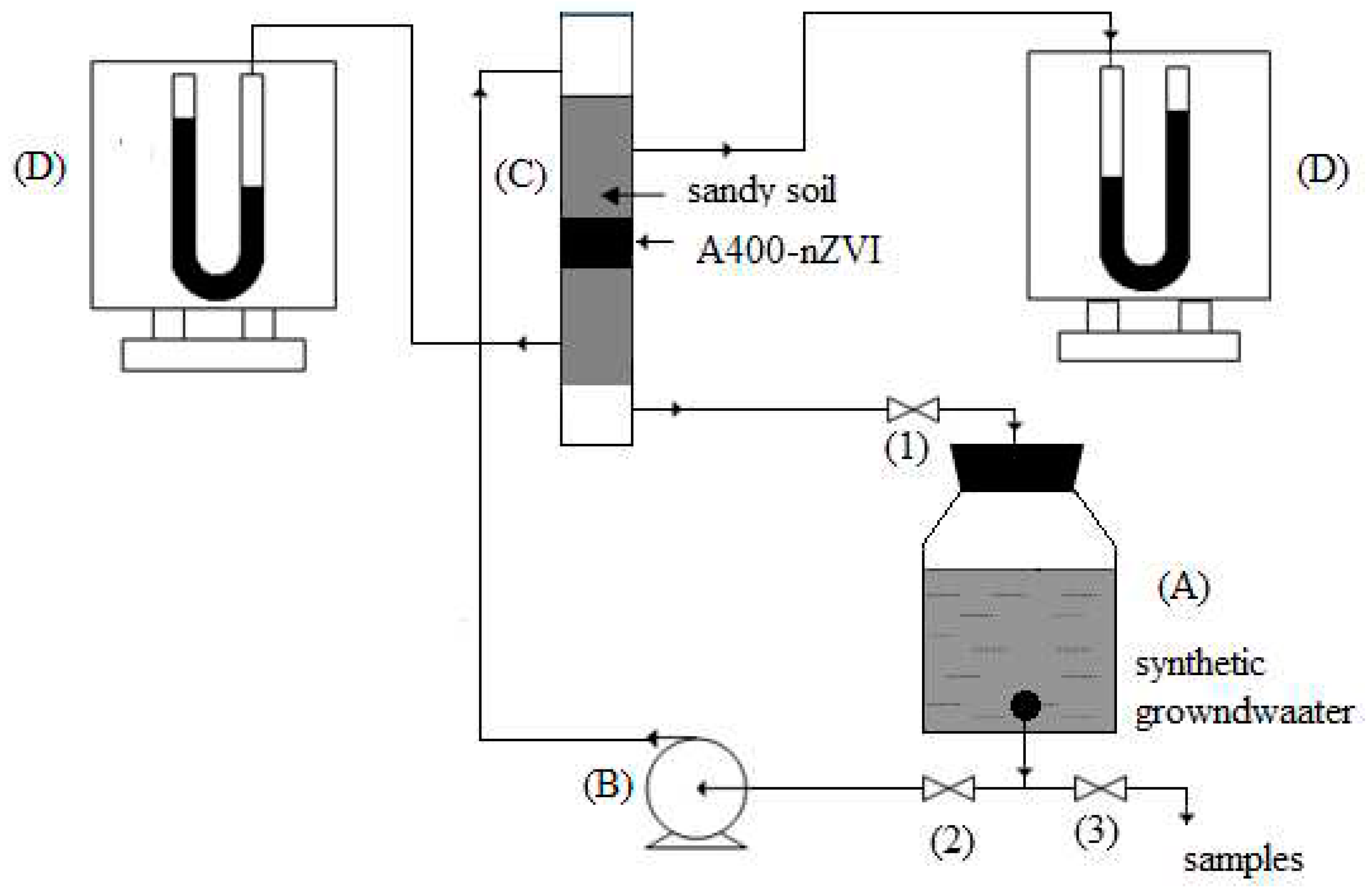
The soil columns used in the miscible displacement experiments of the potassium nitrate solution will be obtained by manually introducing the air-dried sandy type soil. The column used is cylindrical, made of glass with an inner diameter of 3 cm, with a total length of 50 cm, and the height of the soil layer is approximately 30 cm,
Figure 2. In the middle of the soil column, a layer of several centimeters of adsorbent material type A400-nZVI. After filling the column, the soil is saturated with a 100 mg/L KNO
3 solution, and the effluent is collected in fractions of 25 mL in continuous flow with a flow rate Q
1= 14 mL/min, Q
2= 16,8 mL/min, Q
3= 28 mL/min. Under these conditions, the soil column is continuously fed and recirculated with a solution of constant concentration (the ion in the solution) and the reaction products are continuously collected in the effluent until the nitrogen ion concentration in the effluent reaches an acceptable limit value.
Synthetic aquifer groundwater with an initial nitrate concentration of 100 mg/L was pumped using a peristaltic pump, pumping upstream.
The downstream effluent was recirculated and pumped into the upstream reservoir. Recirculation of the contaminated water continued until the nitrate concentration in the effluent was reduced to an acceptable level. Nitrate reduction trend is monitored downstream.
a)
2.5. Kinetics Studies
For the calculation of the sorption speed of N, a kinetic model of the first order is used:
where: C = concentration of N in effluent at time t (mg/L); C
0 = initial concentration of N in the feeding solution (mg/L); k = speed constant of the first order I (h
-1); t = time (h). When the concentration in the effluent reaches half of the initial concentration (C/C
0 = 0.5), the half-life t
1/2 results:
2.6. Calculation of barrier parameters
2.6.1. Conductivitatea hidraulică
To calculate the hydraulic conductivity (k) Darcy's law is used:
2.6.2. Flow rate through the section, or filtration rate
2.6.3. Barrier Permeability (K)
= the modular diameter of the particles (will be calculated based on the texture of the soil and the barrier), mm
φ = porosity
3. Results and Discussions
3.1. Characterization of polymeric materials
The polymeric materials, dried under vacuum condition, without and with zerovalent iron nanoparticles (A400 and A400-nZVI), were characterized using different techniques, such as: Fourier Transforms Infrared Spectroscopy (FTIR), Scanning Electron Microscopy (SEM), EDAX spectrometer, Thermogravimetric analysis (TGA), and X-ray Diffraction (XRD). Also, the dried polymeric materials A400-nZVI, was used as polymeric adsorbent for removal of nitrate ions from a simulated groundwater, in order to demonstrate the adsorption capacity.
3.1.1. SEM-EDAX
Surface morphology of the polymeric materials was performed through a Scanning Electron Microscope (SEM) (Quanta 650 FEG, FEI Company, Hillsboro,
USA), equipped with an EDAX spectrometer (175.6 eV resolution) (
Oxford Instruments, Hillsboro,
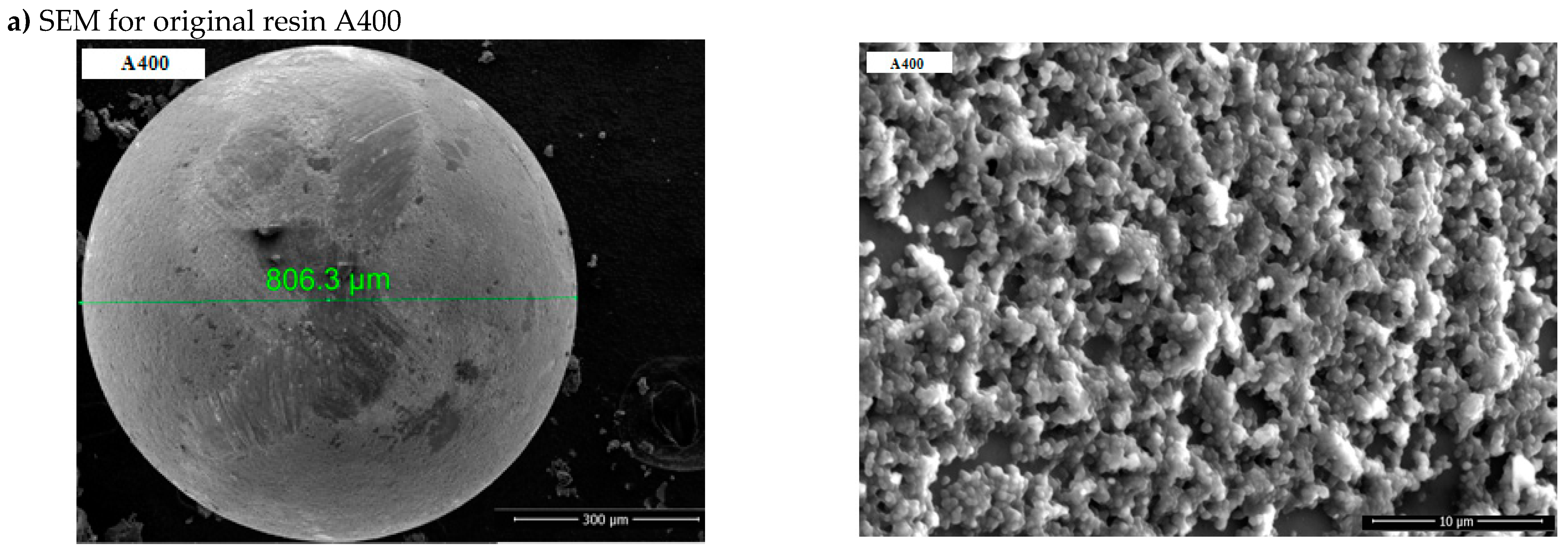
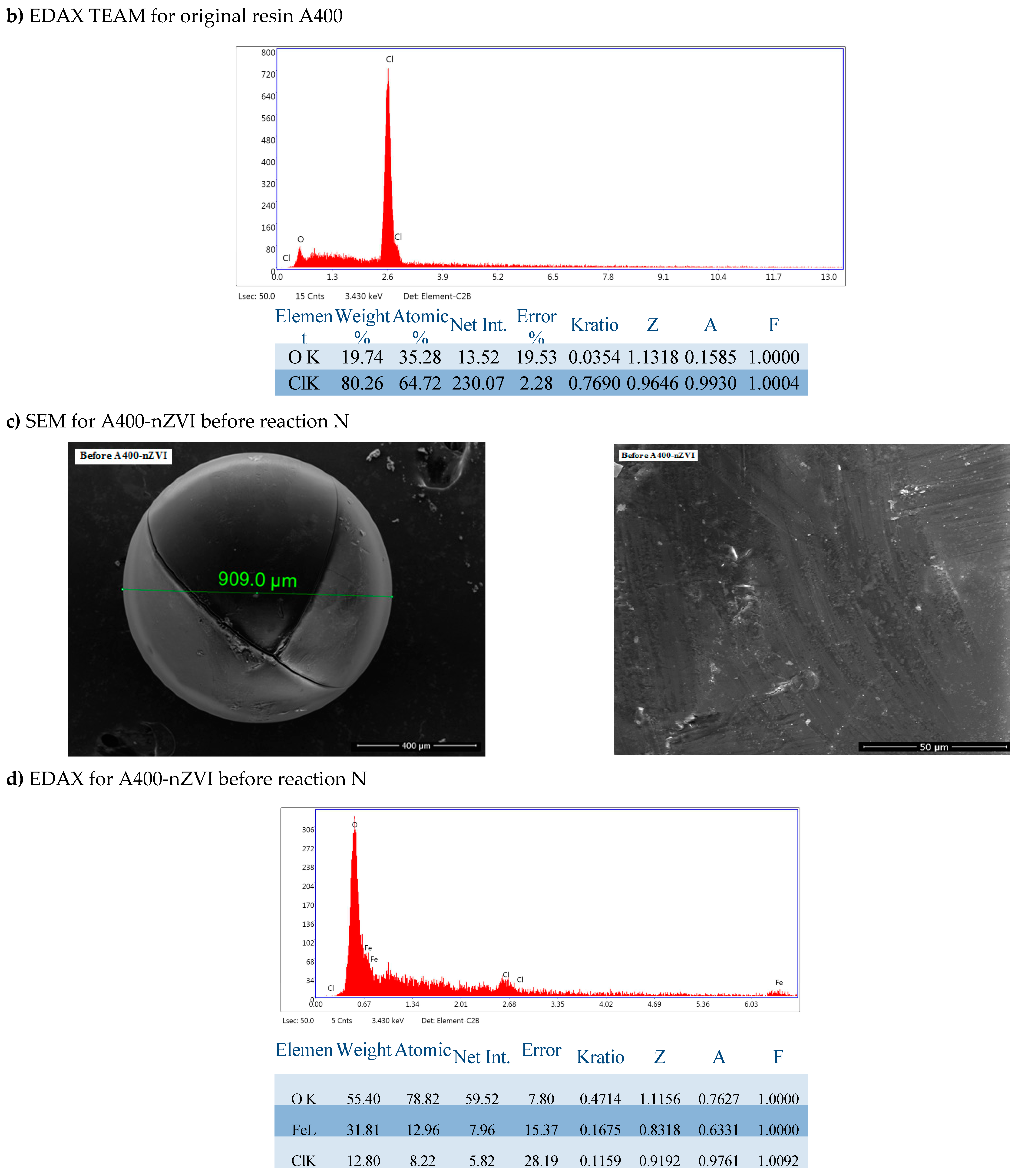
USA). Scanning electron microscopy (SEM) images (magnification of 5000 x) and Energy Dispersive X-ray Spectroscopy (EDAX) spectra of polymeric materials, A400 and A400-nZVI are indicated in
Figure 3a,c.
The SEM image of resin-supported nZVI shows that the iron nanoparticles are uniformly deposited on the resin and confirms the successful attachment of nZVI on the resin (
Figure 3c).
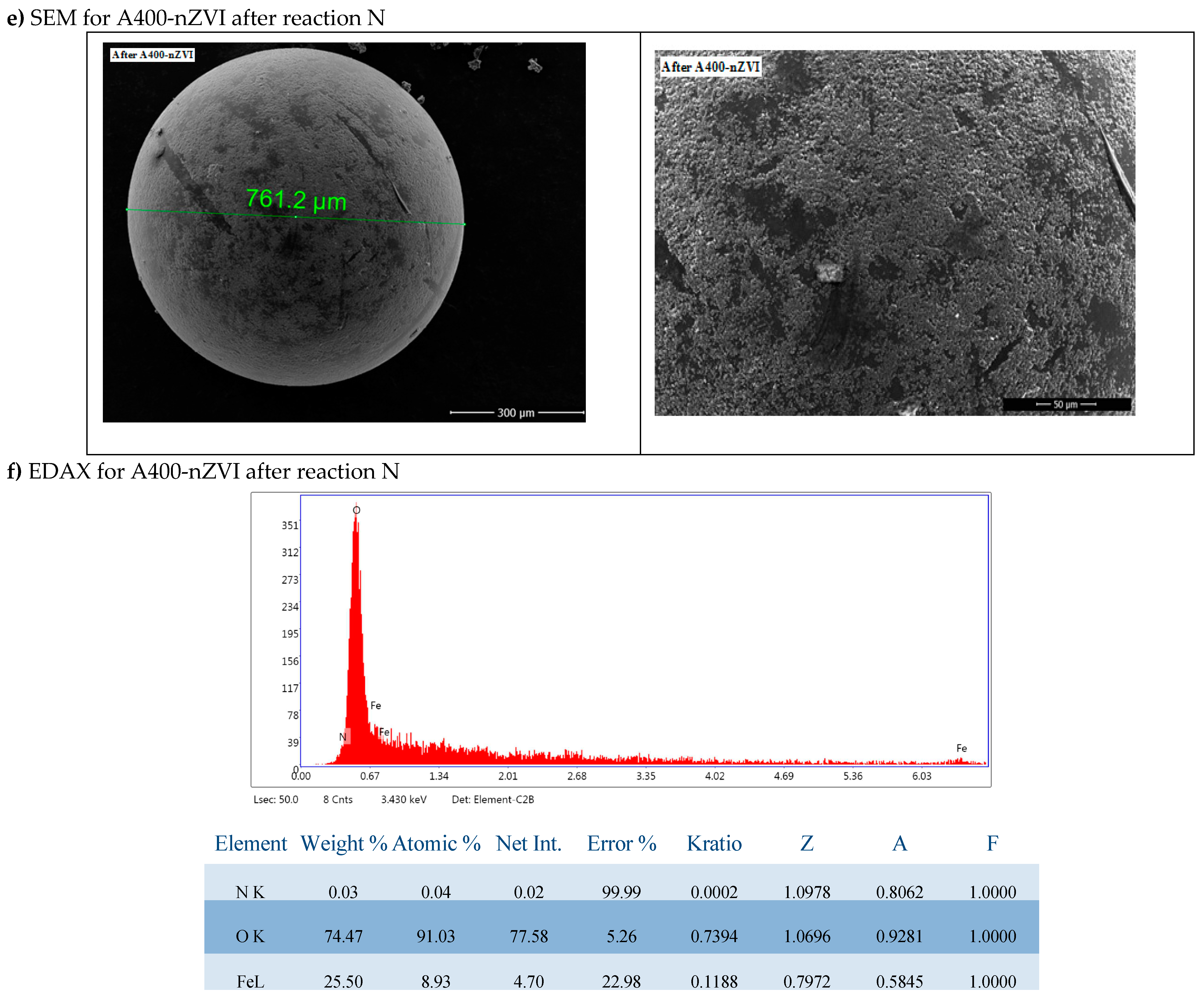
The SEM images (
Figure 4e,f) clearly show that the Fe
0 nanoparticles are presented and dispersed on the A400-nZVI surface.
EDAX analysis of the two forms of polymer resins in the figure showed that Fe0 was distributed on the surface of the resin, the nanoparticles were discrete and dispersed on the surface, indicating that A400 represented a suitable surface for dense and uniform deposition of nanoparticles of Fe0.
As suggested, the precharged nZVI particles will block some internal pores or reduce/narrow the pores. On the other hand, they could offer a more accessible surface and thus increase the specific surface.
The iron nanoparticles deposited on A400-nZVI did not aggregate (the unfavorable characteristic of magnetization and aggregation was eliminated), and the nZVI particles were also dispersed inside the surface of the porous polymeric hosts.
It is shown in the SEM and EDAX images of A400 and A400-nZVI that A400 presented a typical porous structure. This result suggests that nZVI was uniformly immobilized/fixed in A400 resin (Figure a). Compared to A400, a more abundant pore structure was observed on the surface of A400-nZVI (Figure b), where the surface is very dense and compact.
3.1.2. FTIR
The infrared spectra of the polymeric materials were registered on a FTIR spectrophotometer (PerkinELMER, Ltd, London, United Kingdom) in the transmittance mode equipped with a Golden Gate unite. Data were performed in the wavenumber range between 4000 and 650 cm−1, with a resolution of 4 cm−1.
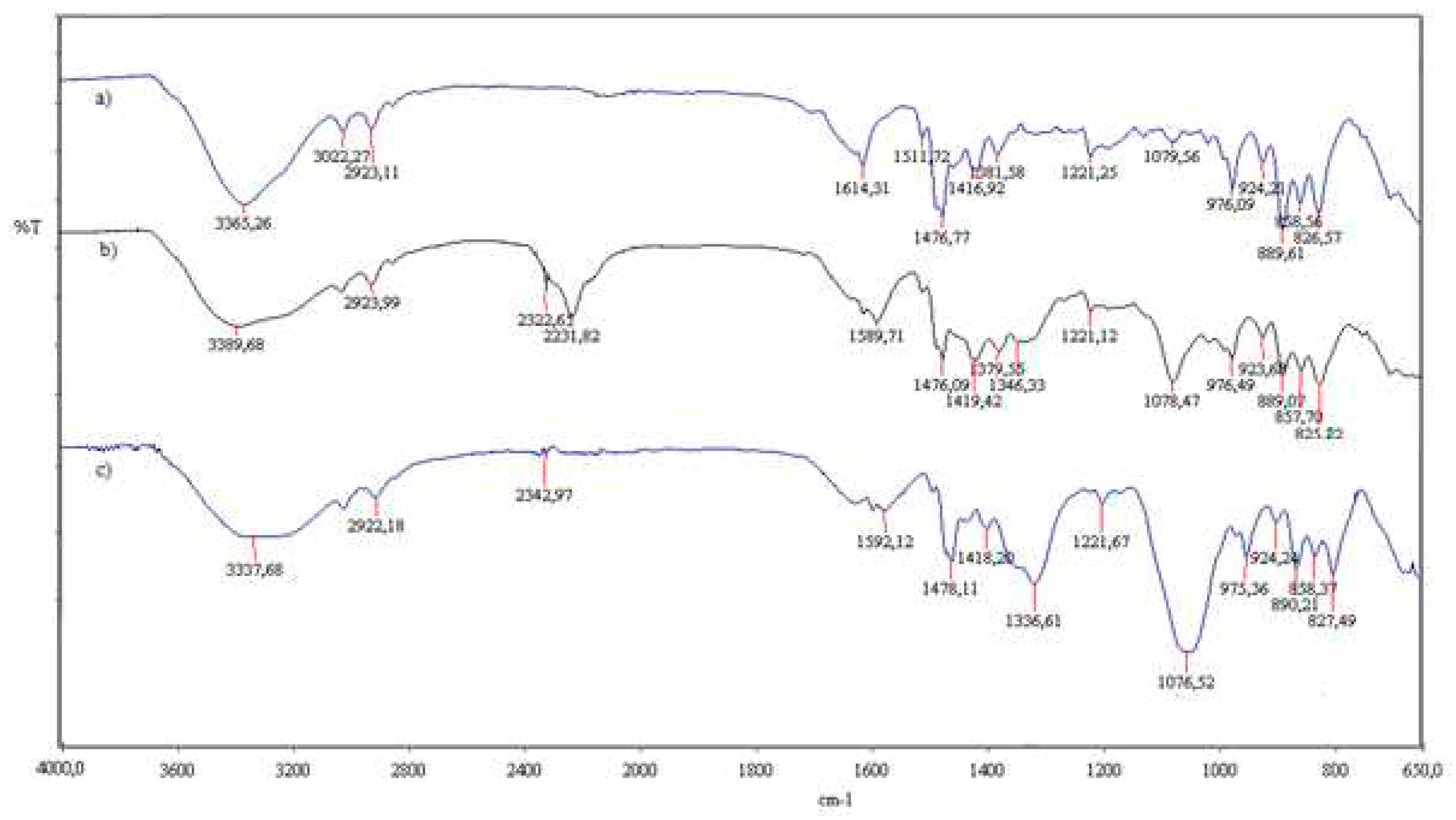
Figure 4 is the FTIR spectrum of the spectra for A400 and A400-nZVI before and after contact with
.
New peaks at 2322 cm−1 and 2231 cm−1 appeared in the spectrum of fresh A400-nZVI compared to A400-nZVI loaded with , which could be attributed to bending vibration of B–O which was the residual compound after iron reduction using NaBH4 (Figure ). Thus, the distribution of nZVI in A400-nZVI does not result from the distribution of ammonium groups in A400, but is possibly related to NaBH4 diffusion into the polymer phases during the formation of nZVI. A similar phenomenon was also observed by Gasparovicova´ et al. (Gasparovicova´ et al., 2007).
The presence of a band at the wave number 2231 cm
-1 is due to the –C≡N bond (stretching vibration) of the nitrile group, the group

has no characteristic bands. The appearance of a peak at 2923cm
-1 may be due to the group – CH
2– (acrylic) stretching vibration, asymmetric, C-H bond (reticulated resin).
The peak at 1381.58 cm−1, 1379.55 cm−1and 1336.61 cm−1 (O-H bending vibration) indicated the presence of surface hydroxyls on nZVI. After adsorption, a portion of hydroxyl groups reacted, and this peak moved to a lower wave number (1336.61 cm−1) and increased in intensity. The fact that the 1379 cm−1, 1346 cm−1 peak does not move to a higher but a lower wavenumber indicates that reduction is occurring and not adsorbing. No additional peaks appeared in the spectra loaded with compared to fresh A400-nZVI.
The bands at 827 cm−1 corresponding to Fe-O, Fe-O-Fe oxygen-iron stretching vibration of Fe2O3 and Fe3O4 in the spectra, indicating that the nZVI particles were partially oxidized.
3.2. Kinetics Evaluation
3.2.1. Experimental determination of curves in dynamic regime and calculation of kinetic parameters of the process
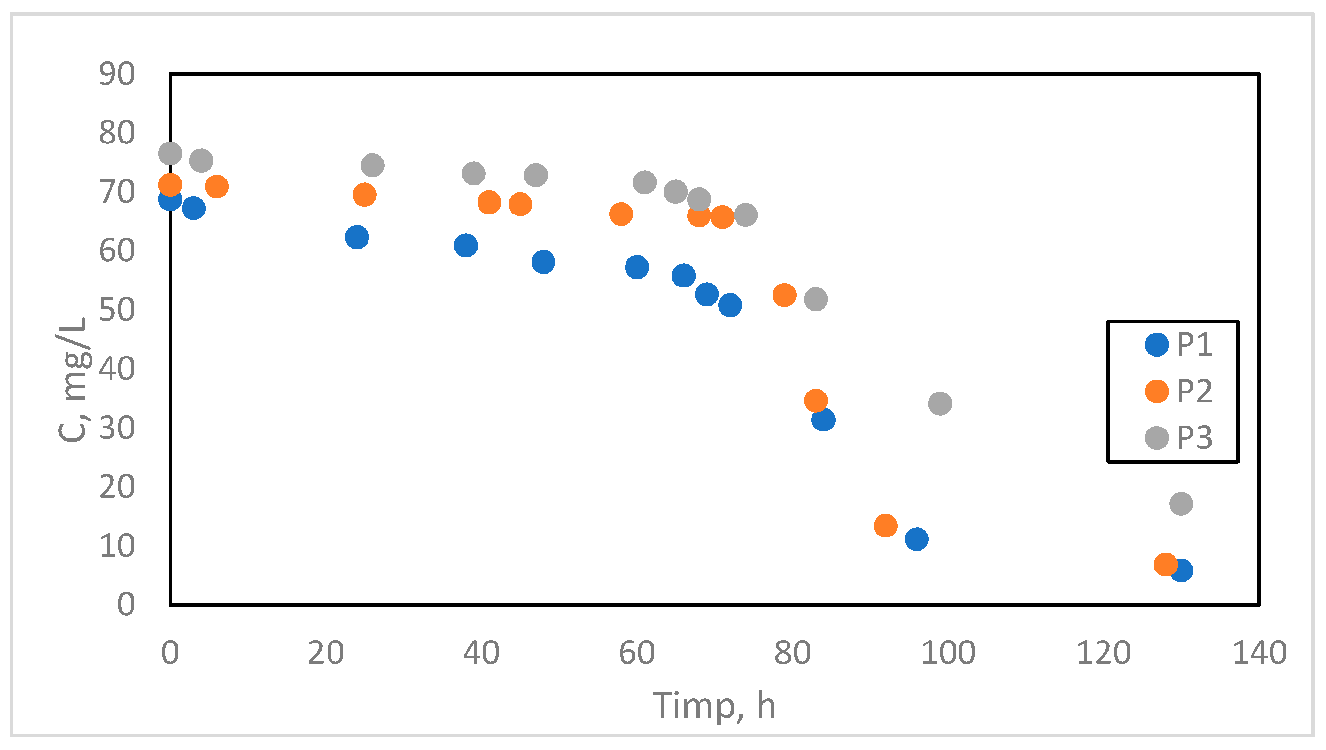
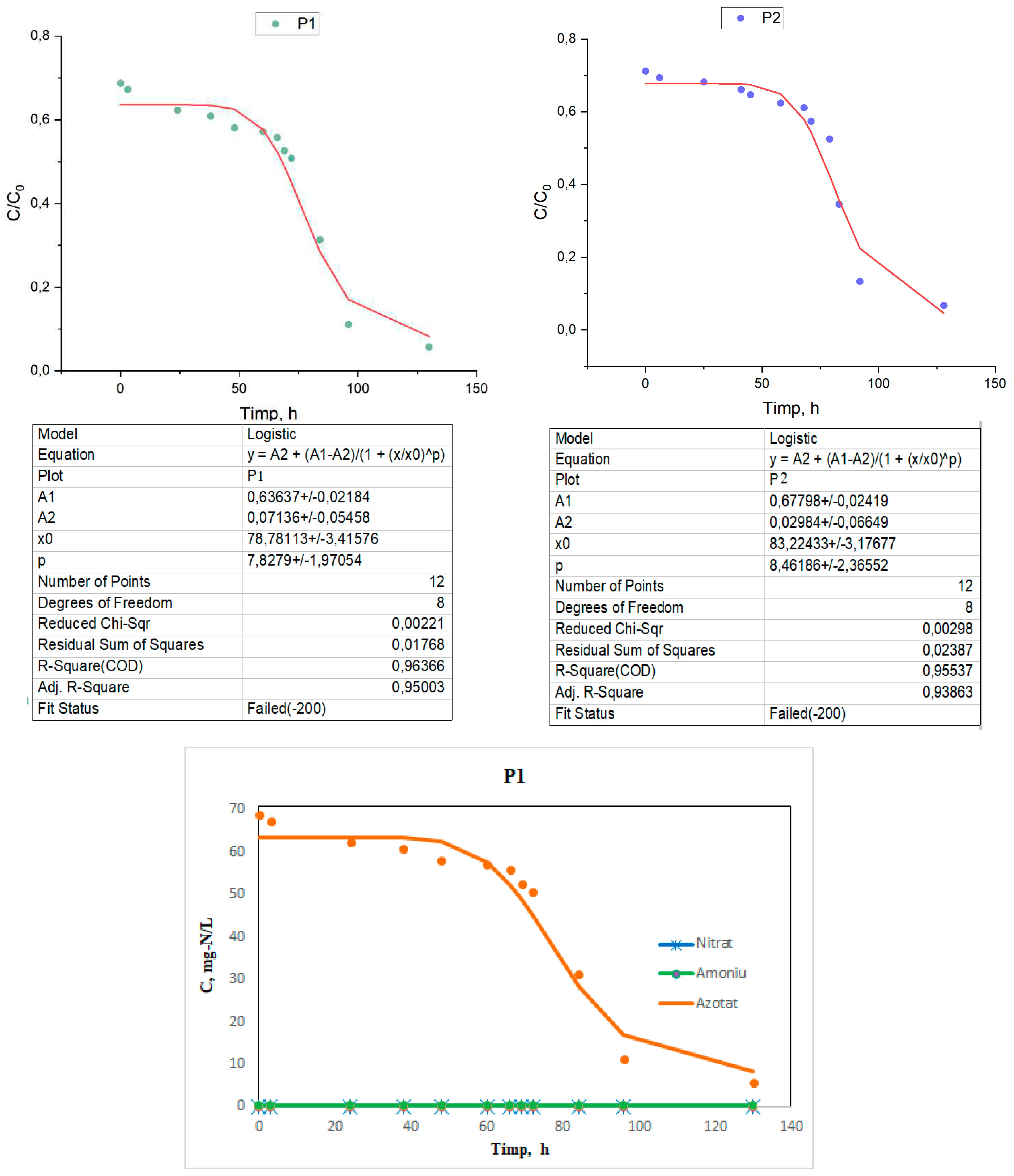
The experimental data are presented in the form of logistic curves under the specified working conditions as a variation of the N concentration in the effluent as a function of time for the three types of flow Q1= 14 mL/min, Q2= 16,8 mL/min, Q3= 28 mL/min, denoted by P1, P2 and P3 (sample P1, P2 and P3 Tabel 1).
The experimental data on the basis of which the curves will be drawn are presented in table 6.1.
Table 1.
Experimental data regarding the variation of the absolute concentration of
ions as a function of time for the three types of flows (
Table 1), for C
0 = 100 mg/L.
Table 1.
Experimental data regarding the variation of the absolute concentration of
ions as a function of time for the three types of flows (
Table 1), for C
0 = 100 mg/L.
| P1 |
P2 |
P3 |
| Timp (h) |
(mg/L)
|
Timp (h) |
(mg/L)
|
Timp (h) |
(mg/L)
|
| 0 |
68,75 |
0 |
71,2 |
0 |
76,5 |
| 3 |
67,2 |
6 |
70,9 |
4 |
75,3 |
| 24 |
62,3 |
25 |
69,5 |
26 |
74,5 |
| 38 |
60,9 |
41 |
68,2 |
39 |
73,1 |
| 48 |
58,1 |
45 |
67,9 |
47 |
72,8 |
| 60 |
57,2 |
58 |
66,2 |
61 |
71,6 |
| 66 |
55,8 |
68 |
66,0 |
65 |
70 |
| 69 |
52,6 |
71 |
65,7 |
68 |
68,7 |
| 72 |
50,79 |
79 |
52,5 |
74 |
66,1 |
| 84 |
31,36 |
83 |
34,6 |
83 |
51,8 |
| 96 |
11,1 |
92 |
13,4 |
99 |
34,1 |
| 130 |
5,76 |
128 |
6,8 |
130 |
17,1 |
The experimental data from
Table 1 regarding the ionic and redox exchange process in the fixed layer for the three types of flow rates.
Figure 5.
The variation of nitrate concentration in the samples to be analyzed as a function of time at the three operating flow rates.
Figure 5.
The variation of nitrate concentration in the samples to be analyzed as a function of time at the three operating flow rates.
By testing the A400-nZVI barrier, a reduction of the nitrate concentration to a value close to 0 was achieved within 5 days, with effluent recirculation every day. For a more in-depth investigation of the nitrate reduction process in the column system, a graph was made showing the nitrate removal efficiency as a function of the number of effluent recirculations (
Figure 1), which was reached in 5 days. It is noteworthy that the maximum nitrate reduction occurs during the seventeenth to seventeenth circulation (Cir16 to Cir17).
For the verification and interpretation of the data, a logistic mathematical model was used, which represents an important tool widely used to solve several practical problems, both in the design phase and in the operation phase of the BRP, such as:
- -
determining the thickness of the reactive medium layer along the barrier
- -
determination of the standing time of the water,
- -
the evaluation of the economic potential as a result of the adequate design of the operating parameters, which cannot be modified during the remediation
The logistic curve is a growth-limited curve that has the shape of an oblong S-shaped curve. It characterizes an evolution that starts from the lower asymptotic limit with the zero value, and finally reaches an upper limit. At first the evolution proceeds slowly, similar to simple exponential growth. Then the growth accelerates, meanwhile it passes through an inflection point, after which the growth slowly decreases, thus the evolution asymptotically heading towards the upper limit.
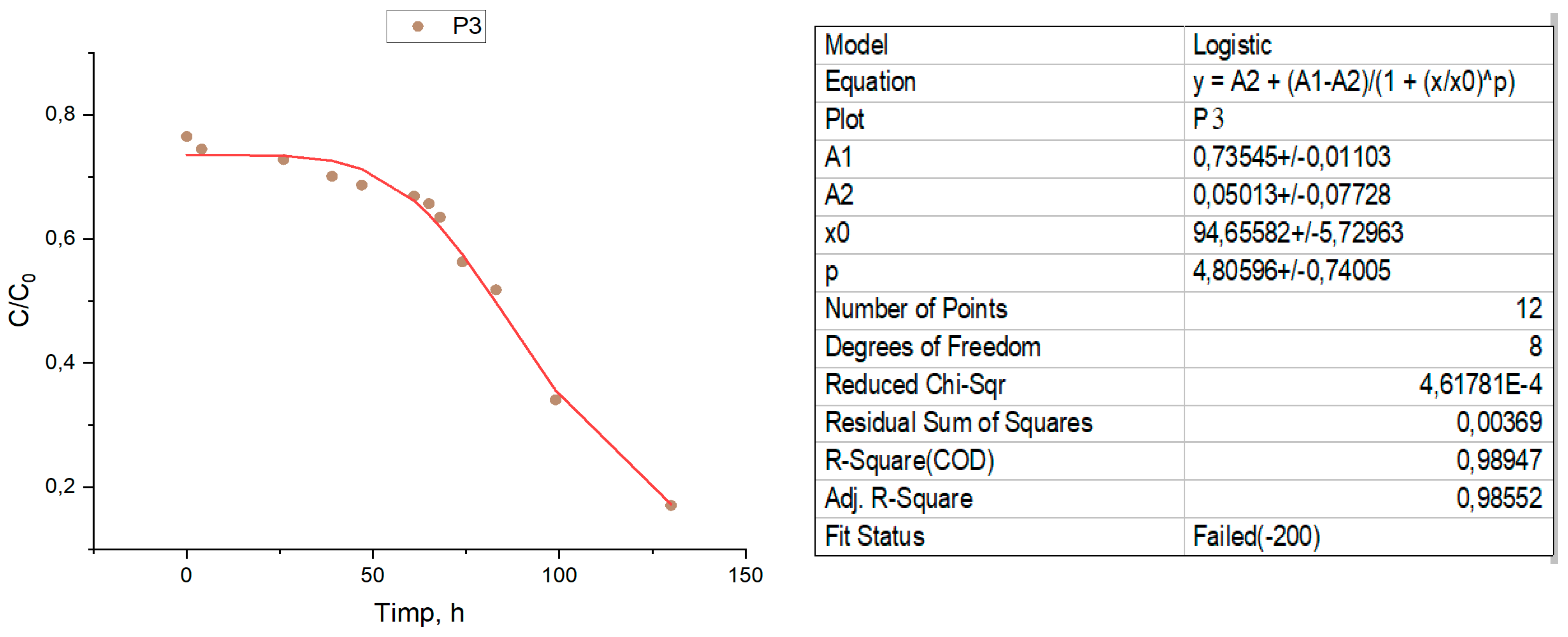
Figure 6.
Logistic curves compared to the experimental points for the three samples.
Figure 6.
Logistic curves compared to the experimental points for the three samples.
It should be noted that the removal efficiency is progressive, but not very accelerated at the beginning of the process, this fact would be attributed to two processes, first are the redox processes, in which the iron in the Fe0 state reacts with nitrogen ions, and on as soon as the exchange positions are freed, ion exchange processes appear simultaneously, which will contribute to accelerating the removal of the nitrogen ion.
From the examination of the curves represented for the three samples in relation to the position of the experimental points, it is found that the removal kinetics of nitrogen ions can be described mathematically precisely enough by logistic equation models.
During the tests, nitrite was not detected in most samples and no accumulation was detected (
Figure 7). This suggests that denitrification by the acceptor A400-nZVI was rapid and nitrite ions were rapidly converted to ammonium after generation. Ammonium concentration was also not detected and this can be attributed to adsorption by the ion exchange resin. However, considering the low regulatory limit of ammonium, it is important to monitor the concentration of this ion, especially in heavily contaminated sites.
Based on the data in table 6.1. and using relation (1)-(2) the characteristic parameters of the first-order kinetic model, t
1/2 and k, are calculated, under dynamic conditions for the three types of flows (
Table 2).
The cumulative mean percentage of nitrate removal observed for each run indicates that the half-life for nitrate degradation is about three days and more than 90% of the NO3- has been degraded after about 5 days.
The rate of worsening of the remediation conditions of N-polluted groundwater will be all the more alert the longer the half-life of N is and vice versa. The half-life t1/2 of the N content varies depending on the working conditions, regarding the variation of the infiltration rate and the precipitation regime.
3.3. Calculation of the yield (η) of nitrogen ion removal
The removal efficiency (η) of the nitrogen ion from the water is determined. A graph is drawn of the yield (η) of nitrogen ion removal over time. A graph is drawn to express the formation of the nitrate and ammonium ions over time.
where:
Ci – concentration of nitrogen ions from the initial sample, mg/L
Ci – the concentration of nitrogen ions removed from the residual water, mg/L
Table 3.
The removal efficiency (η) of the nitrogen ion from synthetic water.
Table 3.
The removal efficiency (η) of the nitrogen ion from synthetic water.
| η1, % |
η2, % |
η3, % |
| 31,5 |
28,8 |
23,5 |
| 32,8 |
30,6 |
25,5 |
| 37,7 |
31,8 |
27,2 |
| 39,1 |
33,9 |
29,9 |
| 41,9 |
35,3 |
31,3 |
| 42,8 |
37,6 |
33,1 |
| 44,2 |
38,9 |
34,3 |
| 47,4 |
42,6 |
36,5 |
| 49,21 |
47,5 |
43,7 |
| 68,64 |
65,4 |
48,2 |
| 88,9 |
86,6 |
65,9 |
| 94,24 |
93,2 |
82,9 |
3.4. Calculation of barrier parameters
3.4.1. Hydraulic conductivity
To calculate the hydraulic conductivity (k) Darcy's law is used:
= the hydraulic gradient = 7
L = column length = 100 cm
It operates at three flow rates Q
1, Q
2, Q
3, so we will have to calculate 3 hydraulic conductivities:
Q from [
is converted to [
3.4.2. Flow rate through the section, or filtration rate
3.4.3. Barrier Permeability (K)
= the modular diameter of the particles (it will be calculated based on the texture of the soil and the barrier)
Table 4.
BRP Parameters.
| Q, m3/s |
k, m⋅s-1
|
v, m⋅s-1
|
K, m2
|
| Q1
|
0.23⋅10-2
|
1.64⋅10-4
|
2.17⋅10-7
|
| Q2
|
0.28⋅10-2
|
1.97⋅10-4
|
| Q3
|
0.47⋅10-2
|
3.27⋅10-4
|
Contaminant removal with BRP occurs mainly in the zone of reactive media and in some cases, down the gradient of the barrier, depending on the type of media used.
Some of the reactive media remove contaminants by direct contact, while other reactive media modify/involve biogeochemical processes in the treatment area, thus ensuring favorable conditions for immobilization of contaminants or (bio)degradation. The primary objective of BRP, regardless of the design used, is to bring contaminants into the reactive zone where they can be destroyed or immobilized.
The average resin diameter was ∼1.2 mm. The size is related to the permeability of the media, this parameter being very important for the successful operation of a permeable reactive barrier. The material selected should minimize constraints on groundwater flow and the particle size should not be excessively small. The permeability of the doped nZVI was higher than that of the aquifer (~10-3 cm/s). This suggests that the created material can be used as a reactive medium for permeable reactive barriers.
3.5. Adsorption Mechanism
Nitrate is a stable and chemically unreactive species that occurs as part of the nitrogen cycle. Nitrate (NO3–) is the most oxidized form of combined nitrogen for oxygenated systems (equations (4.1) and (4.2)).
However, nitrate can be reduced by microbial and chemical processes to nitrite, ammonia, nitrogen oxides and nitrogen gas under various environmental conditions (equation (4.3)
Nitrate contamination of groundwater is governed by natural biogeochemical processes that control nitrate leaching into groundwater. In the root zone of the topsoil, nitrogen fixation and nitrification processes make nitrogen available to plants in the form of ammonium (NH4+) and nitrate. Nitrate reduction can occur through plant uptake, mineralization-immobilization processes, volatilization, runoff losses, and denitrification. (Huno, 2018)
These processes, either independently or in combination, limit the flow of nitrate to groundwater. However, nitrate ions, unlike positively charged NH4+ (which are bound to negatively charged soil particles), are weakly bound and can percolate beyond root zones into the water table of the groundwater aquifer environment. Microbial denitrification is common in soils with more than 60% pore saturation, where oxygen for microbial respiration is limited. Microbial reduction of nitrate ion is a respiratory process that uses nitrate or nitrite as the terminal electron acceptor under conditions of limited oxygen supply.
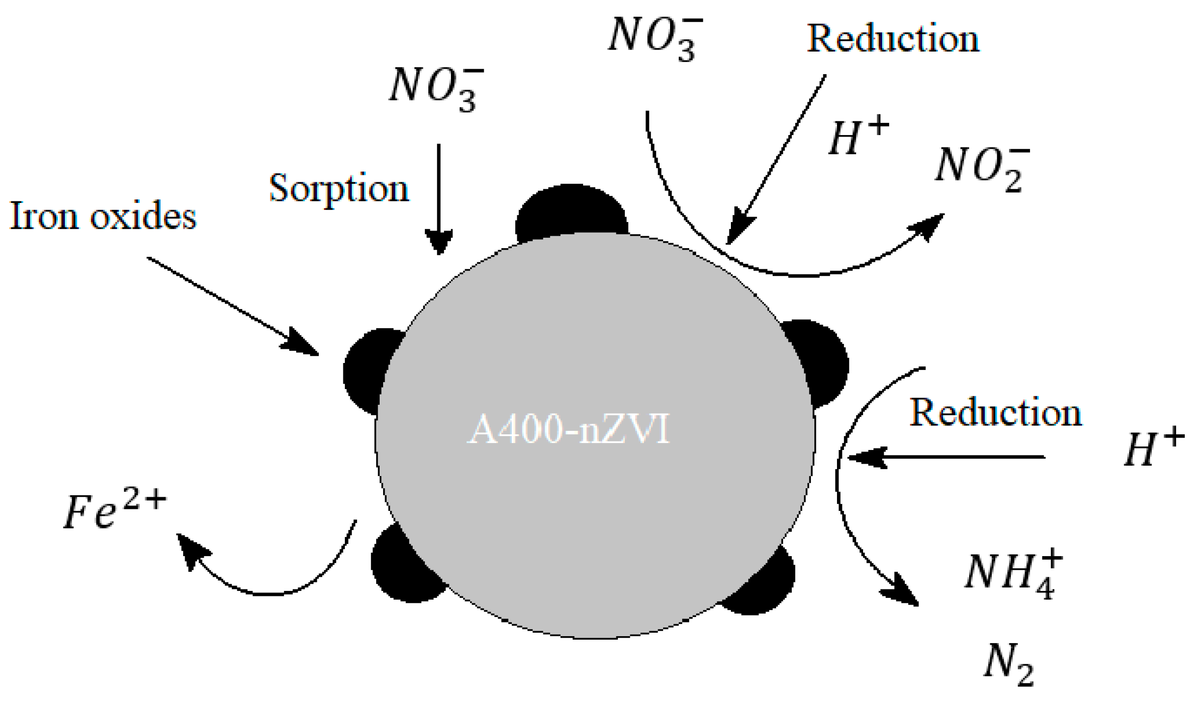
The nZVI reaction is a nitrate reduction reaction to
(nitrite), NH
4+ (ammonium) and N
2 (nitrogen). ZVI is oxidized to Fe (II). The main chemical reaction equations of denitrification are summarized here:
Figure 8.
Scheme of the nitrate reduction mechanism with nZVI. (Rohard, 2020).
Figure 8.
Scheme of the nitrate reduction mechanism with nZVI. (Rohard, 2020).
The core of the nZvi particle consists mainly of zero-valent iron and provides the power to reduce reactions with environmental contaminants. The coating is mostly iron oxides/hydroxides formed from the oxidation of zero-valent iron.
To date, ZVI applications have mainly focused on the electron-donating properties of ZVI. Under ambient conditions, ZVI is quite reactive in water and can serve as an excellent electron donor, making it a versatile remedial material. (Li, 2006)
There are problems with these reactions, first of all: under neutral conditions, corrosion of nZVI produces iron oxides. These products provide a barrier layer on the nZVI particles, which decrease the reaction rate due to a decrease in mass transfer. The second aspect is represented by the main products of the reaction: nitrites and ammonium are also contaminants. (Rohard, 2020)
4. Conclusion
The paper proposes a method of depollution of wastewater contaminated with nitrates through adsorption processes by testing new materials used as adsorbents to remove nitrogen ions so that the removal efficiency of these ions from wastewater is maximum. New adsorbents of the type A400-nZVI will be considered.
The use of polymers containing quaternary ammonium groups as a support for nZVI confers some advantages: the uncharged functional groups allow anionic and cationic contaminants to penetrate into the polymer phase, the ferric ion can be strongly chelated by the nitrogen-containing pyridine groups as donor atoms, therefore, a high content of immobilized nZVI can be achieved and the release of iron ions into water can be avoided or ameliorated due to the strong chelating properties of the functional groups.
The results of the study and the experiments carried out show that the obtained ion exchange type material doped with nanovalent iron had a very good nitrate removal yield. These materials, as well as other types of materials, can be injected into the soil. One of the ways that can be used for permeable reagent barriers on laboratory scale tests is column tests.
By testing the A400-nZVI barrier, a reduction of the nitrate concentration to a value close to 0 was achieved within 5 days, with effluent recirculation every day. For a more in-depth investigation of the nitrate reduction process in an aquifer, the nitrate removal efficiency was tracked as a function of the number of effluent recirculations, which was achieved in 5 days. It is noteworthy that the maximum nitrate reduction occurs during the seventeenth to seventeenth circulation (Cir16 to Cir17).
The cumulative mean percentage of nitrate removal observed for each run indicates that the half-life for nitrate degradation is about three days and more than 90% of the NO3- has been degraded after about 5 days. It should be noted that the removal efficiency is progressive, but not very accelerated at the beginning of the process, this fact would be attributed to two processes, first are the redox processes, in which the iron in the Fe0 state reacts with nitrogen ions, and on as soon as the exchange positions are freed, ion exchange processes appear simultaneously, which will contribute to accelerating the removal of the nitrogen ion.
During testing, nitrite was not detected in most samples and no accumulation was detected. This suggests that denitrification by the acceptor A400-nZVI was rapid and nitrite ions were rapidly converted to ammonium after generation. Ammonium concentration was also not detected and this can be attributed to adsorption by the ion exchange resin.
Permeable reactive barrier technology appears to be a promising approach to effective groundwater remediation, even in complex cases where traditional pump and treat methods and/or microbiological techniques have proven unsuccessful.
Although the use of PRBs is limited to certain site conditions, where the application is feasible, they appear to be a good choice with good acceptance by end users, especially in urban and built-up areas. The reasons for this situation can be seen, for example, in the low use of land, low visibility and no additional impact on the landscape by equipment such as containers, water tanks, pumps or noise produced by rolling machines, etc.
These BRPs can be synthesized in the laboratory by simple and economical methods. They present exceptional properties such as high specific surface area, increased porosity, high anion exchange capacity and good thermostability, which makes them ideal for wastewater treatment.
Acknowledgements
This work has been funded by University Politehnica of Bucharest, through the “National Grant” Program, UPB – GNaC 2018 ARUT. Identifier: UPB- GNaC 2018 ARUT, Ctr. No. CH37-18-01, Code 32
Bibliography
- Amphlett, J.T.M., Ogden, M.D., Foster, R.I. N. Syna, K. Soldenhoff, C. A. Sharrada, Polyamine functionalised ion exchange resins: Synthesis, characterisation and uranyl uptake. Chemical Engineering Journal, 334. pp. 1361-1370. ISSN 1385-8947, (2018). [CrossRef]
- L. Chekli, B. Bayatsarmadi, R. Sekine, B. Sarkar, A. Maoz Shen, K.G. Scheckel, W. Skinner, R. Naidu, H.K. Shon, E. Lombi, E. Donner, Analytical characterisation of nanoscale zero valent iron: A methodological review, Analytica Chimica Acta 903:13-35, (2016). [CrossRef]
- Nathalie Sleiman, Veronique Deluchat, Mahmoud Wazne, Martine Mallet, Alexandra Courtin-Nomade, Veeronique Kazpard, Michel Baudu, Phosphate removal from aqueous solution using ZVI/sand bed reactor: Behavior and mechanism, Water Research 99 (2016) 56-65. [CrossRef]
- R.Thiruvenkatachari, S.Vigneswaran, R.Naidu, Permeable reactive barrier for groundwater remediation, Journal of Industrial and Engineering Chemistry, Volume 14(2): 145-156, (2008). [CrossRef]
- Shamim, M. A., Ghumman, A. R., Ghani, U., Forecasting Groundwater Contamination Using Artificial Neural Networks, International Conference on Water Resources & Arid Environment, Pakistan, (2004).
- Tan, K. The Application of Neural Networks to UNIX Computer Security. In Proceedings of the IEEE International Conference on Neural Networks, Vol.1 pp. 476-481, (1995). [CrossRef]
- Yu-Hoon Hwang, Do-Gun Kim, Hang-Sik Shin, Mechanism study of nitrate reduction by nano zero valent iron, Journal of Hazardous Materials 185:1513–1521, (2011). [CrossRef]
- Zhenmao Jiang, Lu Lva, Weiming Zhang, Qiong Du, Bingcai Pan, Lei Yang, Quanxing Zhang, Nitrate reduction using nanosized zero-valent iron supported by polystyrene resins: Role of surface functional groups, Water Reseaech 45:2191-2198, (2011). [CrossRef]
- Zhenmao Jianga, Shujuan Zhanga, Bingcai Pana,Wenfeng Wanga, Xiaoshu Wangc, Lu Lva, Weiming Zhanga, Quanxing Zhang, A fabrication strategy for nanosized zero valent iron (nZVI) – polymeric anion exchanger composites with tunable structure for nitrate reduction, Journal of Hazardous Materials 233–234:1–6, (2012). [CrossRef]
- USEPA, “Permeable Reactive Barrier Technologies for Contaminant Remediation”, EPA/600/R-98/12, 1998.
- USEPA, „In Situ Remediation Technology Status Report: Treatment Walls”, EPA 542-K94-004, 1995.
- USEPA, ITRC, RTDF.” In Situ Permeable Reactive Barriers: Application and Deployment Training Course”, Boston, Ma, 22-23, 1999.
- Amphlett, J.T.M., Ogden, M.D., Foster, R.I. N. Syna, K. Soldenhoff, C. A. Sharrada (2018), Polyamine functionalised ion exchange resins: Synthesis, characterisation and uranyl uptake. Chemical Engineering Journal, 334. pp. 1361-1370. ISSN 1385-8947. [CrossRef]
-
Demirbas E., Kobya M., Senturk E, Ozkan T. (2004), Adsorption kinetics for the removal of chromium (VI) from aqueous solutions on the activated carbons prepared from agricultural wastes, Water SA, vol. 30(4), 533-539. [CrossRef]
- Jialu Shi, Chao Long, Aimin Li, (2016), Selective reduction of nitrate into nitrogen using Fe–Pd bimetallic nanoparticle supported on chelating resin at near-neutral pH, Chemical Engineering Journal 286:408-415. [CrossRef]
- Jialu Shi, Shengnan Yi, Honglei He, Chao Long, Aimin Li, (2013), Preparation of nanoscale zero-valent iron supported on chelating resin with nitrogen donor atoms for simultaneous reduction of Pb2+ and , Chemical Engineering Journal 230:166–171. [CrossRef]
- Kassim O. Badmus, Elizabeth Coetsee-Hugo, Hendrik Swart, Leslie Petrik, (2018) Synthesis and characterisation of stable and efficient nano zero valent Iron, Environmental Science and Pollution Research. [CrossRef]
- L. Chekli, B. Bayatsarmadi, R. Sekine, B. Sarkar, A. Maoz Shen, K.G. Scheckel, W. Skinner, R. Naidu, H.K. Shon, E. Lombi, E. Donner, (2016), Analytical characterisation of nanoscale zero valent iron: A methodological review, Analytica Chimica Acta 903:13-35. [CrossRef]
- Yanmei Zhou, Bin Gao, Andrew R. Zimmerman, Hao Chen, Ming Zhang, Xinde Cao, Biochar-supported zerovalent iron for removal of various contaminants from aqueous solutions, Bioresource Technology 152 (2014) 538–542. [CrossRef]
- Yu-Hoon Hwang, Do-Gun Kim, Hang-Sik Shin, (2011), Mechanism study of nitrate reduction by nano zero valent iron, Journal of Hazardous Materials 185:1513–1521. [CrossRef]
- Zhenmao Jiang, Lu Lva, Weiming Zhang, Qiong Du, Bingcai Pan, Lei Yang, Quanxing Zhang, (2011), Nitrate reduction using nanosized zero-valent iron supported by polystyrene resins: Role of surface functional groups, Water Reseaech 45:2191-2198. [CrossRef]
- Zhenmao Jianga, Shujuan Zhanga, Bingcai Pana,Wenfeng Wanga, Xiaoshu Wangc, Lu Lva, Weiming Zhanga, Quanxing Zhang, (2012) A fabrication strategy for nanosized zero valent iron (nZVI) – polymeric anion exchanger composites with tunable structure for nitrate reduction, Journal of Hazardous Materials 233–234:1– 6. [CrossRef]
|
Disclaimer/Publisher’s Note: The statements, opinions and data contained in all publications are solely those of the individual author(s) and contributor(s) and not of MDPI and/or the editor(s). MDPI and/or the editor(s) disclaim responsibility for any injury to people or property resulting from any ideas, methods, instructions or products referred to in the content. |
© 2023 by the authors. Licensee MDPI, Basel, Switzerland. This article is an open access article distributed under the terms and conditions of the Creative Commons Attribution (CC BY) license (http://creativecommons.org/licenses/by/4.0/).
 has no characteristic bands. The appearance of a peak at 2923cm-1 may be due to the group – CH2– (acrylic) stretching vibration, asymmetric, C-H bond (reticulated resin).