
Submitted:
22 November 2023
Posted:
23 November 2023
You are already at the latest version
Abstract
The paper deals with an electrothermal model of a thermoelectric converter dedicated to performing simulations of coupled thermal and electrical phenomena taking place in harvesting processes. The proposed model is used to estimate the electrical energy gain from waste heat that would be sufficient to supply electronic circuits, in particular autonomous battery-less nodes of wireless sensor networks (WSN) and Internet of Things (IoT) devices. The developed model is not limited to low power electronic solutions such as WSN or IoT; it can also be scaled up and applied to simulations of considerably higher thermal power conversion. In the paper, a few practical case studies are presented that show the feasibility and suitability of the proposed model for complex simultaneous simulation processes, in both electrical and thermal domains. The first example deals with a combined simulation of the electrothermal model of a thermoelectric generator (TEG) and an electronic harvester circuit based on Analog Devices’ power management integrated circuit LTC3108. The second example relates to the thermalization effect in heat sink-less harvesting applications that could be mitigated by a pulse mode operation.
Keywords:
thermal energy harvesting
; thermoelectric module
; TEG
; IoT
; WSN
; electrothermal simulations
; thermalization effect
1. Introduction
The proliferation of Internet of Things (IoT) devices [1] and the rapid development of wireless sensor networks (WSN) nodes, numbering now to a quantity many times higher than the total number of people worldwide [2], has forced many R&D teams to search for self-powering electronics and battery-less energy sources to ultimately bring the paradigm of completely autonomous WSN/IoT systems (in terms of energy resources and connectivity) much closer to reality (see Figure 1). This necessity mainly results from the fact that the IoT and WSN elements are very often installed in harsh, difficult-to-reach locations or remote environments, far from power mains grids that deliver the necessary energy to power sensors and communication devices. The use of batteries also does not solve the problem of IoT powering because they need periodic replacement or recharging, which results in a significant increase in maintenance costs. Moreover, batteries are chemically hazardous, which imposes additional risk on the environment. That is why energy harvesting from freely available environmental sources of energy has attracted great research attention [3,4,5,6]. Apart from very well-recognized free energy sources being subjects of energy harvesting applications, like heat, light [7,8,9], mechanical vibrations [10,11,12] and electromagnetic background [13,14,15], hybrid harvesting systems are also being developed [16,17] and new solutions investigated as pyroelectric or triboelectric [18,19,20].
From the above-mentioned ambient energy sources, heat energy and thermoelectric conversion play increasingly important roles in the field of energy harvesting and energy scavenging, although the heat-to-energy conversion efficiency still leaves much to be desired. On the other hand, thermoelectric modules (TEM), which are devoid of moving components, offer the advantages of quiet and reliable operation with an exceptionally long Mean Time to Failure (MTTF) coefficient. Waste heat is very often abundant in industrial environments and temperature gradients typically change more gradually compared to the abrupt bursts of vibrations that often occur spontaneously. This is why thermoelectric generators can offer a consistent and uninterrupted source of energy that is relatively easily convertible by power management circuits.
The development of heat energy harvesting by means of thermoelectric modules is nowadays greatly enhanced by improvements and progress that proceed in three parallel paths. One is the material science that provides new materials for thermoelectric couples exhibiting far higher figures of merit ZT in the room temperature range than the traditional Bi2Te3 [21,22,23,24]. The second path is the advancements in the construction and geometry of thermoelectric modules, with segmented legs that can achieve much higher efficiencies and high output power densities of over 2.1 W/cm2 [25,26].
The third path results from recent developments in the design of electronic circuits and the microelectronics industry. There are both energy efficient converters and power management integrated circuits (ICs) for energy harvesting [27,28,29,30] and ultra-low power microcontrollers and wireless transceivers that have such low energy requirements that they can be powered by human warmth alone. For example, in [31] a low temperature thermal energy harvesting system that supplies power to wireless sensing modules was demonstrated, capable of transmitting the collected temperature, current and voltage measurements. In [32] a wearable thermoelectric power generator using body heat to supply power to low-power human diagnosis devices (sensor nodes) is presented; the experimental results show that the power of a single TEG module reaches about 250 μW at a temperature difference of around 5 °C. Advances in microelectronics and semiconductor technology have enabled the miniaturization of thermoelectric modules, making them suitable for integration into compact and portable devices such as wearables, IoT sensors, and medical instruments.
The motivation behind the proposed work is the development of an efficient model of a thermoelectric converter for a thermal energy harvesting process simulation that will consider the thermoelectric materials’ parameters, the TEG mechanical construction (including heat sink optimization), as well as inclusion of an electronic circuit for power conversion. The complex thermoelectric converter model is suitable for simulation experiments carried out on a common platform, namely the electronic circuit simulator SPICE-like software. The proposed model uses the electro-thermal analogy where the thermal quantities, such as heat power, temperature, thermal resistance and capacitance, are replaced by equivalent electrical quantities, respectively the current source, voltage, electrical resistance and capacitance. The model is useful in the assessment and performance prediction of a customized energy harvester and self-powered electronic system, before developing a costly prototype. It can be used to estimate the available electrical energy harvested from waste heat that would be required to supply electronic circuits (in particular, autonomous battery-less nodes of wireless sensor networks (WSN) and IoT), or at least to support a primary battery that prolongs the lifetime of the nodes. The developed model is not limited to only low-power electronic solutions such as IoT or WSN, but it can also be scaled up and applied to simulations of considerably higher thermal power conversion.
This article is organized as follows: in section 2, we describe the detailed process of the thermoelectric harvester modelling and the equivalent representation in the LTspice. In section 3, we present the basic simulated operations of the TEG, demonstrating its performance characteristics; for example, the available output power against current or resistive load and changing temperature conditions. In section 4, we show practical, real scenarios and results of simulation experiments, followed by a discussion. The first example deals with a combined simulation of the electrothermal model of a thermoelectric generator (TEG) and an electronic harvester circuit based on Analog Devices’ power management integrated circuit LTC3108. The second example relates to a thermalization effect in heat sink-less harvesting applications that could be mitigated by a pulse mode operation.
2. Model of a Thermoelectric Converter
A typical thermoelectric harvester (Figure 2) consists of a thermoelectric module attached to a heat source and a heat sink to create a temperature gradient ΔT over TEM that is next converted at an open circuit into a Seebeck voltage VS by the Seebeck coefficient S (1). Heat sink dimensions are very often much higher than TEM, which hinders miniaturization of the whole system. When the electric circuit is closed by an external load RL, the output voltage VOUT and harvested power PL can be observed as shown in equations (2) and (3) respectively.
where R stands for an internal resistance of the TEM, including resistance of the bismuth telluride Bi2Te3 and the resistance of the copper strips connecting the thermoelectric pellets.
2.1. Approaches to Modeling Thermoelectric Converters
As the demand for thermoelectric harvesters/converters grows, designers encounter the challenge of creating a straightforward yet precise model for simulations. This requires an accurate numerical representation of their performance parameters across various operating conditions [33]. Modeling behavior of thermoelectric modules (TEMs) has a quite long history. Typically, simulations are conducted using mathematical software, employing numerical techniques, or through electronic and thermal simulators that address the electrical and thermal aspects of the model independently.
In [34], differential equations governing thermoelectric transports were analytically and numerically solved by the Mathematica software tool. This tool is capable of solving the inhomogeneous second order differential equation for the temperature profile, even for non-constant coefficients with mixed boundary conditions. Thus, exact temperature profiles along the pellet could be easily calculated, including the temperature dependence of the material properties.
The electro-thermal operation of energy harvesters based on thermoelectric modules is a complex process and in-depth insights require 3D numerical methods. Another approach uses the numerical models of thermoelectric generators implemented by means of finite element method (FEM). In [35], an effect of geometric design and height of the TEM legs on the optimal output voltage was studied. In [36] the ANSYS Workbench software was used to model a TEM in which the Peltier, Joule, and Thomson effects were included in the heat equation. A holistic 3D finite element simulation model for a thermoelectric power generator element implemented into COMSOL Multiphysics software was demonstrated in [37].
Finite element-based methods give accurate results and fortunately, calculating the module's performance in a steady state is sufficient to meet the accuracy required for validation of the design requirements. Nonetheless, electronic engineers often find such complex tools impractical because they do not allow quick results. What is even more important to take into consideration is that the FEM methods are not suitable for the simulation of coupled energy harvesters and electronic circuits at the same time, which is crucial in the customized TEG development process. Moreover, the energy harvesting system has to undergo simulations when it is running overtime and is subjected to various external conditions, in particular, changing temperatures and the electrical load that the TEG has to cope with. In this context, the most adequate and reliable approach is to use an electronic circuit-like simulator and an electro-thermal analogy.
2.2. Electro-Thermal Analogy Based TEG Model
The first models of the thermoelectric modules that were implemented into electronic circuits’ simulators were working in the cooling mode. In [38], an analysis of a developed PSPICE-compatible equivalent circuit of a thermoelectric cooler was demonstrated, whereas in [39,40] an electrothermal macromodel of an active heat sink based on TEM for cooling process simulation was described. In [41], a modified electrothermal model of TEMs was demonstrated, with temperature dependent material properties taken into consideration. The electrothermal models of TEMs working as thermogenerators differ from coolers in that an extra circuit has to be added that models a voltage source resulting from the Seebeck effect [42,43,44].
In our work, we assume a one-directional heat flow from a heat source through a TEM to a heat sink. All components in the harvesting system stack are transformed into a lumped network of equivalent thermal resistances and capacitances reflecting heat conductance and accumulation, as well as current sources corresponding to heat sources. Figure 3 shows a detailed structure of the layers of the thermoelectric generator and the corresponding equivalent electrothermal circuit components.
The heat source can be modelled as a current source Qp if the power of the heat source attached to the TEM is known, or as a voltage source reflecting temperature Th when the heat to the TEM is delivered from a source characterized by infinite heat capacity at constant temperature Th.
The resistors RthAl2O3 and capacitors CthAl2O3 mimic the thermal resistance and capacitance of alumina layer Al2O3, which is the outer surface of the TEM; it exhibits very high thermal conductance and extremely low electrical conductance. The RthCu and CthCu are the thermal resistance and capacitance (respectively) of the copper strips which connect the thermoelectric pellets in series. The parallel thermal circuit consisting of Rthhs and Rthhs is responsible for modelling heat accumulation and dissipation by the heat sink (made of aluminum) to the air. Finally, the heat power sources Qc and Qh represent the heat powers of the cold and hot sides of the TEM respectively.
Apart from the “active” layer Bi2Te3, the remaining layers of the TEG are passive and the values of thermal resistances can be calculated based on the thermal conductivity coefficient of the appropriate materials, the cross-section area and the thickness of a specific layer. The thermal capacitance can be estimated based on the volume of the layer and the specific heat parameter of the material. The “active” part of the TEM is described by the equations expressing the thermal and electrical power balance across the TEG (4)-(7).
where Qc represents heat power at the cold side of TEM [W], Qh is heat power at the hot side of TEM [W], P is electrical power delivered to or generated by TEM [W], I is electrical current flowing through TEM [A], V is voltage over TEM terminals [V], Tc is temperature at the cold side of TEM [K], Th is temperature at the hot side of TEM [K], S is total Seebeck coefficient of TEM [V/K], R is total electrical resistance of TEM [Ω] and K is total thermal conductance of TEM [W/K].
In the proposed model, the nonlinear thermal dependencies of the relevant thermoelectric parameters, such as the Seebeck coefficient, electrical resistance and thermal conductivity, are included and are expressed as temperature functions S(T), R(T) and K(T).
2.3. Electrothermal Model of a TEG Based On the Low-cost Themoelectric Module TEC1-12706
The proposed model is used in the development of cost-effective battery-less electronic systems that are powered by thermoelectric generators or combined TEGs and other sources of harvested energy (e.g. photovoltaic or vibrations) [45]. Therefore, we subjected to modeling the low-cost, commercially-available thermoelectric module TEC1-12706 (one of the cheapest modules on the market). Its dimensions are 40 mm x 40 mm x 3.9 mm. At 50 °C it has the maximum heat power Qmax=57 W, maximum current Imax=6.4 A and maximum voltage Vmax=16.4 V.
Thermal resistances and capacitances of the passive layers of the modelled TEM were calculated in accordance with the description given in section 2.1. For the active part, before the equivalent model was developed the most important parameters (namely R, S and K values) were extracted. In [46,47], experimental techniques for the determination of these parameters (from observable variables obtained from temperature, voltage, and electric current measurements made on a working TE device) were proposed. Another more convenient technique for extracting temperature-dependent data concerning the three critical parameters of a heat energy harvesting system was proposed in [48] and was also used in this work. Temperature functions of R, S, and K were calculated from the performance plots provided by the TEM manufacturer. From the graphs showing the relationship of the voltage and heat power at the cold side of the TEM against the temperature gradient, R can be determined first (8), next S (9) and finally K (10). The linear approximation of the temperature dependence obtained from the calculations for the total resistance R, Seebeck coefficient S, and thermal conductance K of the TEC1-12706 are given in Figure 4.
Table 1 presents the extracted values of the components for the equivalent circuit model of the TEC1-12706 working as a thermoelectric converter. The coefficients ’a’ and ’b’ express the linear approximation of the temperature dependence of the parameters R, S and K, according to the linear function y=ax+b. The complete equivalent circuit of the thermoelectric converter based on TEC1-12706 is shown in Figure 5.
In the thermal part of the equivalent model, the three parallel current sources Qcn on the left side of the circuit and the three Qhn on the right mimic heat power sources of the cold and hot side of the TEG respectively. They originate directly from the equations (4) and (5), consisting of three components reflecting the Peltier effect, Joule heat generation and the heat conduction. The heat power sources Qcn and Qhn are controlled by auxiliary voltage sources with values of R, S and K calculated continuously at mean temperature Tmean across the module (11). The detailed description of Qcn and Qhn, as well as Seebeck voltage VS modelled in the LTspice, are shown in Figure 6.
In the electrical part of the model the generated output Seebeck voltage appears between terminals V+ and V-. The internal resistance is controlled by an auxiliary voltage source delivering a value of Rmean proportional to the Tmean.
For simplicity of the simulation exercise, the complex electrothermal model is hidden from the enduser with a hierarchical structure in the LTspice tool. The final component that can be used in prototype circuits and systems is represented by a five-terminal symbol (Figure 7). Terminals 1, 2 and 3 correspond to the ambient, hot and cold side temperatures respectively, whereas V+ and V- correspond to the output voltage.
3. Simulated Basic Operations of the TEG and Performance Assessments
In the following subsections a few important operations of the TEG TEC1-12706 are modelled. The obtained characteristics and results give a much deeper insight into the behavior of the thermoelectric converter than the data sheets provided by TEM manufacturers and allow for performance assessments in the various conditions that the TEG may face in real operating conditions.
3.1. Seebeck Voltage at Open Circuit Mode of Operation
The relationship between the Seebeck output voltage at open circuit and the temperature gradient ∆T across the TEG can be modelled and predicted in the equivalent thermal circuit shown in Figure 8.
The voltage sources VTa, VTc and VTh represent the ambient Ta, cold Tc side and hot Th side temperatures of the TEG respectively. The simulations were performed with various temperature gradient values, with Tc specified as a parameter and Th declared as a variable. The obtained results enable the estimation of the highest voltage ratings in the absence of loads. They can be highly beneficial when designing DC-DC boost regulators necessary to increase the voltage and to fulfill the requirements of electronic circuits, such as sensor network nodes. As expected, the plots shown in Figure 8 prove that the Seebeck voltage is proportional to the temperature gradient across the TEG and that the module TEC1-12706 can provide at least V=510 mV at ∆T=10 °C, and as much as V=3,06 V at ∆T=60 °C.
3.2. Maximum Available Outut Power and Maximum Power Transfer Point
Figure 9 illustrates the output power PL in function of the current load IL at different temperature differences between TEG sides; the temperature of the cold side is constant and set to Tc=20 °C, whereas the hot side temperature Th changes in 20 °C increments. From the plots it can be estimated that the maximum output power from the generator (at ∆T=100 °C) exceeds 1.6 W, and when ∆T=40 °C it is only 100 mW.
Figure 10 shows the relationship between the output power PL and a resistive load RL at various temperature gradients ΔT. By analyzing the simulated functions, one can identify the optimal matching points (points of maximum power transfer MPPT) between RL and the internal resistance of the thermoelectric module.
3.3. Influnce of Thermal Resistance of a Heat Sink on Output Power
Figure 11 demonstrates the output power PL in function of the thermal resistance Rth_heat_sink of a heat sink at various temperature differences between the TEG sides; the temperature of the cold side is constant and set to Tc=20 °C whereas the hot side temperature changes in 20 °C increments. The matched load resistance was set to 2.5 Ω as it follows the results presented in Figure 10. The plots show a strong dependence of the output power PL on the thermal resistance of the heat sink, which plays an essential role in the energy conversion process and significantly contributes to the overall efficiency of the TEG, but on the other hand it is very cumbersome as its dimensions are bulky and thus it often takes up much more space than the TEM and the WSN node combined.
4. Results of Numerical Simulations of Real Scenarios and Discussion
The graphs presented in Figure 8, Figure 9, Figure 10 and Figure 11 give very useful data about the static boundary operating conditions that the TEG can work in, as well as the available voltage and power it can deliver to supply electronic systems or WSN nodes. However, the electrothermal model of the TEG fully demonstrates its capabilities and usefulness in simulations of dynamic processes in the time domain. Two practical, real-life scenarios are discussed below.
4.1. Combined Operation of a TEG and a Power Management Circuit
A single thermoelectric generator is not able to directly deliver the level of output voltage sufficient to power electronic circuits and WSN nodes, especially when working in relatively low temperature gradients. Therefore, DC-DC converters have to be used [27] [49,50].
The objective of the numerical experiments presented below was to test how well the developed TEG model works with an ultra-low voltage step-up converter and the power management circuit LTC3108, as well as to estimate the available power after DC-DC conversion and the conversion efficiency.
The main advantage of the LTC3108 is that it takes extremely low quiescent current from very low input voltage sources such as TEGs or small solar cells. The input step-up circuitry of the LTC3108 consists of a small step-up external transformer. It starts from input voltages as low as 20 mV, which predestines it to low temperature gradients TEGs in particular. For example, the TEC1-12706 gives 50 mV Seebeck voltage at ∆T=1 °C and 25 mV output voltage when it is connected to a matched resistive load. It provides a complete power management solution for wireless sensing and data acquisition because it manages multiple outputs with very low power consumption requirements: a low drop out voltage regulator provides VLDO=2.2 V to power an external microprocessor, where VOUT is the main output with value that can be selected and programmed to four fixed voltages (typically 3.3 V) to power a wireless transmitter or sensors, and VSTORE=5 V (for a battery or storage capacitor). It is also able to generate periodic pulses of higher load current (at VOUT2), which is essential in wireless data transmission.
Figure 12 shows the electrothermal circuit being tested and the plot of the output voltage VOUT from the LTC3108 when the temperature gradient across the TEG is 20 °C. As the TEG starts the conversion of heat energy into electrical and the integrated circuit is boosting the voltage, before the output voltage is kept constant and regulated at 3.3 V it increases linearly, which means that the output capacitor C5=100 µF is charged by a constant current IOUT.
The available maximum output power POUTmax can be estimated according to (12). We performed a series of numerical experiments where ∆T across the TEG was changed from 5 °C to 50 °C and the POUTmax from the LTC3108 was obtained with conversion efficiency η estimated (for a given input power delivered from the TEG).

Table 2.
Estimated output power and conversion efficiency of combined operation of TEG TEC1-12706 and the ultralow voltage converter LTC3108.
Table 2.
Estimated output power and conversion efficiency of combined operation of TEG TEC1-12706 and the ultralow voltage converter LTC3108.
| ∆T [o] |
dVOUT/dt [V/s] |
POUTmax [mW] |
η [%] |
|---|---|---|---|
| 5 | 3.44 | 1.14 | 17.8 |
| 10 | 7.34 | 2.42 | 9.5 |
| 15 | 11.36 | 3.75 | 6.5 |
| 20 | 15.72 | 5.19 | 5.1 |
| 25 | 20.25 | 6.68 | 4.2 |
| 30 | 24.66 | 8.14 | 3.5 |
| 35 | 28.97 | 9.56 | 3.1 |
| 40 | 33.20 | 10.96 | 2.7 |
| 45 | 37.52 | 12.38 | 2.4 |
| 50 | 41.79 | 13.79 | 2.2 |
From the data and graphs displaying POUTmax and η (Figure 13) it can be derived that the maximum output power is almost proportional to the temperature difference, whereas the conversion efficiency is decreasing significantly. This is probably due to the power losses in the step-up transformer when the input current from the TEG increases because the resistance of the secondary winding of the 1:100 transformer is 300 Ω. Therefore, to reduce the power losses and improve the conversion efficiency, for higher temperature differences resulting in increased output voltage from the TEG a transformer with a lower winding ratio should be considered.
The model of the TEG was successfully used in developing a battery-less microelectronic system for remote sensing (Figure 14). The completely autonomous wireless sensor node working in a wireless network, powered by a thermoelectric converter and harvesting heat from a central heating system, was able to take and collect data on humidity and temperature in 60-minute intervals and transmit them every 36 hours. The prototyping stage was preceded by simulation experiments where all of the managed outputs from the LTC3108 were tested (Figure 15). During one of the simulation tests of the LTC3108 supplied by the TEG TEC-12706, the hot side temperature Th was periodically changed every second between Thmax=60 °C and Thmin=20 °C, while the cold side temperature remained constant at Tc=20 oC. The capacitors at VLDO, VOUT and VSTORE were 2.2 µF, 470 µF and 1000 µF, respectively. The current drawn from the VLDO was 100 µA whereas from the VOUT a pulse current IOUT=1 mA was passed to the load in interval times 1-2 s, 5-6 s and 9-10 s.
The power management functionality implemented in the LTC3108 ensures that when sufficient power is delivered by the TEG, the first output voltage is VLDO=2.2 V (green). Next, the capacitor at the VOUT is charged to the selected voltage 3.3 V (blue). If the temperature difference across the TEG drops below a certain value and power delivered by the TEG is not sufficient to regulate both the VLDO and VOUT, priority is given to VLDO and the capacitor at VOUT plays the role of a reservoir of energy to sustain VLDO at 2.2 V (drop of VOUT during the 0-5 s interval is visible in Figure 15). In periods where the VLDO and VOUT are regulated and have constant values the excessive power is stored in the capacitor at VSTORE (red), which is an extra reservoir of energy for VOUT in periods of TEG power deficiency (unless VSTORE is higher than VOUT).
4.2. Termalization Effect and Pulsed Operation of TEG in Heat Sink-less Energy Harvesting Applications
From Figure 11 it is evident that the thermal resistance of a heat sink that is attached to the cold side of the TEG significantly affects the energy conversion process and the output power, which is reduced to zero when Rth_heat_sink approaches infinity. The optimization of thermoelectric harvester design is a challenging task as its goal is to reduce the external dimensions of a heat sink (resulting in reduced thermal conductance) and to increase the output power at the same time.
In [51] a breakthrough idea for a TEG solution without a heat sink was proposed. It improves output power by reducing the thermalization effect - an adverse process of equalizing temperatures on both sides of the TEM when thermal resistance to the ambient temperature is too high. The concept of pulse mode operation of the TEG is presented in Figure 16 and an equivalent electrothermal model with exemplary values for simulation experiments and future development is proposed in Figure 17.
In Phase 1, when the hot surface of the TEM is abruptly attached to a heat source at temperature Th=30 °C and the cold side is exposed to ambient at Ta=20 oC, the effective temperature difference ∆Teff across the module increases rapidly, allowing the output power to reach its maximum value POUTmax=13.94 mW and then gradually decreases to a very low value at equilibrium (thermalization) where ∆Teffmin=0.22 °C and corresponding POUTmin=7.62 µW (Figure 18). The effective temperature difference ∆Teff is the actual temperature gradient between both sides of the TEM (∆Teff=Theff - Tceff), excluding temperature drops over thermal resistances connecting the TEM to the heat source and the ambient. In this case, the thermal resistance between the heat source and the TEM is very low (Rth1=100m K/W) and the thermal resistance between the TEM cold side and ambient is Rth3=62.5 K/W. The Rth3 resulting from thermal convection was calculated according to (13), with convection coefficient h=10 W/(m2K) and TEM surface area (A=4 cm x 4 cm).
In the equivalent electrothermal circuit in Phase 1 the S1 switch is closed and S2 opened, which means that the heat is transferred to the TEG directly from the heat source at temperature Th through a thermal resistance Rth1, and on the other side part of it is dissipated to ambient through Rth3 (the rest of the heat energy is converted to electrical energy and powering RLOAD=2.5 Ω).
In Phase 2, the TEM is abruptly detached from the heat source and both sides of the TEM are exposed to ambient and thus the heat accumulated in the TEM is gradually dissipating. Phase 2 is reflected by the equivalent circuit with closed S2 and opened S1.
When the state of the working TEG changes periodically between Phase 1 and Phase 2, it results in an increased average generated power POUTavg. In Figure 19, the results of the simulations of pulse mode TEG operation are shown. The "/ctrl" signal controls the switches S1 and S2 and the moments in time when the TEM is either attached to the heat source (/ctrl is high) or is detached (/ctrl is low). From the effective temperature plots Tceff and Theff we can see that the thermal time constant at Phase 1 (when the TEG is fed from the heat source) is much lower than in Phase 2 (when the heat accumulated in the TEG is slowly dissipated to the ambient by large convection thermal resistances Rth2 and Rth3). Consequently, in the pulse mode operation, apart from the first period when temperatures at both TEM sides start rising from ambient, in the following periods the temperatures are higher and the peaks of the generated output power are lower (6.76 mW) than at the beginning of the operation (13.94 mW) (Figure 18). However, the average power in the pulse mode operation (POUTavg=85.23 µW) is much higher than in the continuous mode (POUTmin=7.62 µW) when the thermalization process takes place at a high thermal resistance between the TEG cold side and ambient.
The results of a series of numerical simulations of the relationship between the average output power POUTavg and the time of Phase 1 are shown in Figure 20.
The plot proves that for a given total period ttotal of TEG pulse mode operation, the shorter Phase 1 time gives higher average output power. This is because during a very short Phase 1, the effective temperatures at both sides of the TEM cannot equalize and the resulting temperature difference is sufficiently high and secondly, the longer Phase 2 gives the TEM more time to dissipate the accumulated/residual heat and lower both of the effective temperatures as close as possible to the ambient. It means that in the next Phase 1, when the TEM is again attached to the heat source, the instantly generated temperature difference and therefore the output power is higher.
5. Conclusions
In contrast to power generation on a larger scale where the primary focus is on maximizing the conversion efficiency, energy harvesting applications prioritize achieving the highest possible power transfer from an ambient energy source to the load. Hence it is crucial that the entire process, starting from the modeling of the physical phenomena taking place in the transducers, the series of numerical simulations and finally the development of a prototype harvester and the design of an electronic converter, is executed with great care and precision.
The proposed model is a very useful tool in the assessment and performance prediction of a customized energy harvester and self-powered electronic system across various operating conditions before a costly prototype is developed. It makes the development process of an efficient TEG less time consuming. It can be used in the estimation of the small amounts of available electrical energy harvested from waste heat that would be sufficient to supply electronic circuits, in particular, autonomous battery-less nodes of wireless sensor networks, and to set their appropriate duty cycle to execute sensing and transmission activities.
The model supports the design of ultra-low power systems with dedicated specialized power management integrated circuits that do not need external sources to perform certain signal processing and computational tasks. It demonstrates feasibility and suitability for complex simultaneous simulation processes, both in electrical and thermal domains, and also for emerging harvesting technologies. Combining thermoelectric converters with vibrations in the pulse mode TEG operation may contribute to the significant miniaturization of thermoelectric generators by depleting them of bulky heat sinks, thereby making them more suitable for integration into compact and portable devices, such as wearables and medical instruments. The model is freely available online at [52].
Author Contributions
The conceptualization of the paper was done by P.D., P.B., and M.M. P.D. and P.B. performed the theoretical analysis and the coupled simulations of TEG and LTC3108 and validated the results. P.D. and M.M. prepared the model of thermalization effect and performed simulations of the TEG pulse mode of operation and analyzed the results. All authors contributed to writing the manuscript, review and editing. All authors have read and agreed to the published version of the manuscript.
Funding
This research was supported financially by the AGH University of Science and Technology, Krakow, Poland subvention no. 16.16.230.434.
Data Availability Statement
The model with examples is available at [52].
Acknowledgments
The authors express gratitude to the AGH and Jagiellonian University staff for the support and consultations during the preparation of the manuscript.
Conflicts of Interest
The authors declare no conflict of interest.
References
- Global IoT Connectivity Market Report and Forecast 2023-2028. Available online: www.researchandmarkets.com (accessed on 8 November 2023).
- United Nations, Department of Economic and Social Affairs, Population Division, World Population Prospects, United Nations, 2015. Available online: https://esa.un.org/unpd/wpp/Download/Standard/Population/ (accessed on 8 November 2023).
- Priya, S.; Inman, D. J. Energy Harvesting Technologies, Springer New York, 2008, ISBN 978-0-387-76463-4.
- Joseph, A. D. Energy Harvesting Projects, IEEE, 2005, 1536-1268/05.
- Luo, J.; Chen, Y.; Tang, K.; Luo, J. Remote monitoring information system and its applications based on the Internet of Things, BioMedical Information Engineering, In proceedings of the FBIE 2009 International Conference on Future, 13-14 Dec. 2009. pp. 482–485.
- Paradiso J., A.; Starner, T. Energy Scavenging for Mobile and Wireless Electronics, Pervasive Computing, IEEE, Jan.-March 2005, pp. 18-27.
- Shore, A.; Roller, J.; Bergeson, J.; Hamadani, B.H. Indoor light energy harvesting for battery- powered sensors using small photovoltaic modules, Energy Sci Eng. 2021; 9:2036– 2043. [CrossRef]
- Jabbar, H.; Jeong, T. Ambient Light Energy Harvesting and Numerical Modeling of Non-Linear Phenomena, Appl. Sci., 2022, 12, 2068. [Google Scholar] [CrossRef]
- Cumbajín, M.; Sánchez, P.; Núñez, M.; Gordón, C. Energy Harvesting System with Solar Panels to Supply Low Power Electronic Devices. In proceedings of the IOP Conference Series: Earth and Environmental Science, Volume 1141, Congress on Sustainability, Energy and City 2022 12/09/2022 - 13/09/2022 Ambato, Ecuador. [CrossRef]
- Chongfeng, W.; Xingjian, J. A comprehensive review on vibration energy harvesting: Modelling and realization, Renewable and Sustainable Energy Reviews, 2017, Volume 74, pp. 1-18, ISSN 1364-0321. [CrossRef]
- Jiang, J.; Liu, S.; Feng, L.; Zhao, D. A, Review of Piezoelectric Vibration Energy Harvesting with Magnetic Coupling Based on Different Structural Characteristics. Micromachines 2021, 12, 436. [Google Scholar] [CrossRef]
- Kenzhekhanov, T.; Abduvali, D.; Kalimuldina, G.; Adair, D. Investigating the feasibility of energy harvesting using material work functions. Materials Today: Proceedings, Volume 49, Part 6, 2022, Pages 2501-2505, ISSN 2214-7853. [CrossRef]
- Kurt, E.; Issimova, A.; Medetov, B. A wide-band electromagnetic energy harvester. Energy, 2023, Volume 277, 127693, ISSN 0360-5442. [CrossRef]
- Sabat, W.; Klepacki, D.; Kamuda, K.; Kuryło, K.; Jankowski-Mihułowicz, P. Efficiency Measurements of Energy Harvesting from Electromagnetic Environment for Selected Harvester Systems. Electronics 2023, 12, 4247. [Google Scholar] [CrossRef]
- Abdulwali, Z.S.A.; Alqahtani, A.H.; Aladadi, Y.T.; Alkanhal, M.A.S.; Al-Moliki, Y.M.; Aljaloud, K.; Alresheedi, M.T. A High-Performance Circularly Polarized and Harmonic Rejection Rectenna for Electromagnetic Energy Harvesting. Sensors 2023, 23, 7725. [Google Scholar] [CrossRef]
- Dziadak, B. Hybrid Optical and Thermal Energy Conversion System to Power Internet of Things Nodes. Energies 2023, 16, 7076. [Google Scholar] [CrossRef]
- Veloo, S.G.; Tiang, J.J.; Muhammad, S.; Wong, S.K. A Hybrid Solar-RF Energy Harvesting System Based on an EM4325-Embedded RFID Tag. Electronics 2023, 12, 4045. [Google Scholar] [CrossRef]
- Sodige, B.A.K.; Furuno, H.; Ngo, N.C.T.; Sugiyama, H.; Baba, M.; Niihara, K.; Nakayama, T. Improvement of Power Recovery by Applying a Multi-Pulse Electric Field in the Thermoelectric Cycle Power Generation Process with Pyroelectric Materials. Energies 2023, 16, 4728. [Google Scholar] [CrossRef]
- Wang, Y.; Wang, N.; Cao, X. From Triboelectric Nanogenerator to Hybrid Energy Harvesters: A Review on the Integration Strategy toward High Efficiency and Multifunctionality. Materials 2023, 16, 6405. [Google Scholar] [CrossRef]
- Kim, H.; Nguyen, D.C.; Luu, T.T.; Ding, Z.; Lin, Z.-H.; Choi, D. Recent Advances in Functional Fiber-Based Wearable Triboelectric Nanogenerators. Nanomaterials 2023, 13, 2718. [Google Scholar] [CrossRef]
- Dashevsky, Z.; Skipidarov, S. Investigating the Performance of Bismuth-Antimony Telluride. In Novel Thermoelectric Materials and Device Design Concepts; Springer International Publishing: Cham, Switzerland, 2019; pp. 3–21. ISBN 9783030120573. [Google Scholar]
- Zhang, Q.H.; Huang, X.Y.; Bai, S.Q.; Shi, X.; Uher, C.; Chen, L.D. Thermoelectric Devices for Power Generation: Recent Progress and Future Challenges. Adv. Eng. Mater. 2016, 18, pp. 194–213. [Google Scholar] [CrossRef]
- Shi, X.L.; Zou, J.; Chen, Z.G. Advanced Thermoelectric Design: From Materials and Structures to Devices. Chem. Rev. 2020, 120, 7399–7515. [Google Scholar] [CrossRef] [PubMed]
- Yan, Q., Kanatzidis, M.G. High-performance thermoelectrics and challenges for practical devices. Nature Materials 21, 503–513 (2022). [CrossRef]
- Ouyang, Z.; Li, D. Modelling of segmented high-performance thermoelectric generators with effects of thermal radiation, electrical and thermal contact resistances. Scientific Reports 6, 2016, 24123. [CrossRef]
- Olivares-Robles, M.A., Badillo-Ruiz, C.A. & Ruiz-Ortega, P.E. A comprehensive analysis on nanostructured materials in a thermoelectric micro-system based on geometric shape, segmentation structure and load resistance. Sci Rep 10, 21659 (2020). [CrossRef]
- LTC3108 Datasheet and Product Info|Analog Devices. Available online: https://www.analog.com/media/en/technical-documentation/data-sheets/LTC3108.pdf (accessed on 3 November 2023).
- Zhang, P.; Liu, L. A Photovoltaic and Thermal Energy Combining Harvesting Interface Circuit with MPPT and Single Inductor. 2020 IEEE 15th International Conference on Solid-State & Integrated Circuit Technology (ICSICT), Kunming, China, 2020, pp. 1-3. [CrossRef]
- Tang, Y. -W.; Wong, C. -H.; Du, Y.; Du, L.; Li, Y. Chang M. -C. F. A fully integrated 28nm CMOS dual source adaptive thermoelectric and RF energy harvesting circuit with 110mv startup voltage. In Proceedings of 2018 IEEE Custom Integrated Circuits Conference (CICC), San Diego, CA, USA, 2018, pp. 1-4. [CrossRef]
- Veri, C.; Francioso, L.; Pasca, M.; De Pascali, C.; Siciliano, P.; D’Amico, S. An 80 mv startup voltage fully electrical dc–dc converter for flexible thermoelectric generators. IEEE Sensors Journal, 2016, vol. 16, no. 8, pp. 2735–2745. [CrossRef]
- Mateu, L.; Codrea, C.; Lucas, N. ; Pollak, M; Spies, P. Human Body Energy Harvesting Thermogenerator for Sensing Applications, Proc. of the International Conference on Sensor Technologies and Applications SensorComm 2007, October, Valencia, Spain, pp. 366-372.
- Deng, F.; Qiu, H.; Chen, J.; Wang, L.; Wang, B. Wearable thermoelectric power generators combined with flexible supercapacitor for low-power human diagnosis devices. IEEE Transactions on industrial electronics, 2016, vol. 64, no. 2, pp. 1477–1485. [CrossRef]
- Dalola, S.; Ferrari, M.; Ferrari, V.; Guizzetti, D. M.; Taroni, A. Characterization of Thermoelectric Modules for Powering Autonomous Sensors, IEEE Transactions on Instrumentation and Measurement, 2009, volume 58, No. 1, pp. 99-107.
- Seifert, W.; Ueltzen, M.; Strumpel, C.; Heiliger, W.; Muller, E. One-dimensional modeling of a Peltier element. Proceedings of ICT2001. 20 International Conference on Thermoelectrics (Cat. No.01TH8589), Beijing, China; 2001; pp. 439–443. [Google Scholar] [CrossRef]
- Seetawan, T.; Seetawan, U.; Ratchasin, A.; Srichai, S.; Singsoog, K.; Namhongsa, W.; Ruttanapun, C.; Siridejachai, S. Analysis of Thermoelectric Generator by Finite Element Method. Procedia Engineering, 2012, volume 32, pp. 1006-1011, ISSN 1877-7058. [CrossRef]
- Wielgosz, S.E.; Clifford, C.E.; Yu, K.; Barry, M.M. Fully–coupled thermal–electric modeling of thermoelectric generators, Energy, 2023, volume 266, 126324, ISSN 0360-5442. [CrossRef]
- Guangxi, W.; Xiong, Y. A holistic 3D finite element simulation model for thermoelectric power generator element. Energy Conversion and Management, 2014, volume 86, pp. 99-110, ISSN 0196-8904. [CrossRef]
- Lineykin, S.; Ben-Yaakov, S. Analysis of thermoelectric coolers by a spice-compatible equivalent-circuit model, Power Electronics Letter IEEE, 2005, volume 3, Issue 2, pp. 63-66.
- Dziurdzia, P.; Kos, A. Electrothermal Macromodel of Active Heat Sink for Cooling Process Simulation. In Proceedings of the 5th International Workshop on Thermal Investigations of Ics and Microstructures, Rome, 3-6 Oct.1999; pp. 76–81. [Google Scholar]
- Dziurdzia, P.; Kos, A. Tool for fast modelling active heat sinks. In Proceedings of the XVIIth Annual IEEE Semiconductor Thermal Measurement and Management Symposium SEMITHERM, San Jose, USA, 20-22 March 2001; pp. 174–179. [Google Scholar]
- Mitrani, D.; Salazar, J.; Turo, A.; Garcia, M. J.; Chavez, J. A. Lumped and Distributed Parameter SPICE Models of TE Devices Considering Temperature Dependent Material Properties. In Proceedings of the 13th International Workshop on Thermal Investigations of ICs and Systems, Budapest, Hungary, 17-19 Sept. 2007; pp. 202–207. [Google Scholar]
- Lineykin, S.; Ben-Yaakov, S. Spice Compatible Equivalent Circuit of the Energy Conversion Processes in Thermoelectric Modules”, In Proceedings of the 23rd IEEE Convention of Electrical and Electronics Engineers in Israel, 2004.
- Mirocha, A.; Dziurdzia, P. Improved electrothermal model of the thermoelectric generator implemented in SPICE. In Proceedings of the International Conference on Signals and Electronic Systems, 14-17 Sept. 2008, Cracow, Poland; pp. 317–320.
- Chen, M.; Rosendahl, L. A.; Condra, T. J.; Pedersen, J. K. Numerical Modeling of Thermoelectric Generators With Varing Material Properties in a Circuit Simulator, IEEE Transactions on Energy Conversion, March 2009, Vol. 24, No. 1, pp. 112-124.
- Markiewicz M.; Dziurdzia P.; Konieczny T.; Skomorowski M.; Kowalczyk L.; Skotnicki T. and Urard P., "Software Controlled Low Cost Thermoelectric Energy Harvester for Ultra-Low Power Wireless Sensor Nodes," in IEEE Access, vol. 8, pp. 38920-38930, 2020. [CrossRef]
- Mitrani, D.; Tome, J. A.; Salazar, J.; Turo, A.; Garcia, M. J.; Chavez, J. A. Methodology for extracting thermoelectric module parameters. In IEEE Transactions on Instrumentation and Measurement, Aug. 2005, vol. 54, no. 4, pp. 1548-1552. [CrossRef]
- Dziurdzia, P. Measurement Setup for Characterization of Peltier Modules used as Micro Thermoelectric Generators in Smart Wireless Sensor Networks, In Proceedings of the XXXI International Conference of International Microelectronics and Packaging Society Poland Chapter, Rzeszów-Krasiczyn, Poland, 23-26 September 2007, pp. 311-314. [Google Scholar]
- Dziurdzia, P.; Bratek, P.; Brzozowski, I.; Gelmuda, W.; Ostrowski, J.; Kos, A. Extraction of temperature dependent parameters for an electrothermal model of thermoelectric energy harvester, In roceedings of 2016 MIXDES - 23rd International Conference Mixed Design of Integrated Circuits and Systems, Lodz, Poland, 2016, pp. 377-381. [CrossRef]
- Salerno, D. Ultralow Voltage Energy Harvester Uses Thermoeletric Generator for Battery-free Wireless Sensors, LT Journal. Available online https://www.analog.com/media/en/technical-documentation/lt-journal-article/ltjournal-v20n3-01-df-ltc3108_09-david_salerno.pdf.
- Afghan, S.A.; Géza, H. Modelling and Analysis of Energy Harvesting in Internet of Things (IoT): Characterization of a Thermal Energy Harvesting Circuit for IoT based Applications with LTC3108, Energies 2019, 12, 3873. [CrossRef]
- Haras, M.; Markiewicz, M.; Monfray, S.; Skotnicki, T. Pulse mode of operation - A new booster of TEG, improving power up to X2.7 - to better fit IoT requirements. Nano Energy, 2020, volume 68, 104204, ISSN 2211-2855. [CrossRef]
- Dziurdzia, P. Thermoelectric Generator LTspice Model. Available online: https://github.com/piotrdziurdzia/teg (accessed on 14 November 2023).
Figure 1.
The idea of completely autonomous Wireless Sensor Network nodes, in terms of energy resources (Energy Harvesters EH) and connectivity (WSNn).
Figure 1.
The idea of completely autonomous Wireless Sensor Network nodes, in terms of energy resources (Energy Harvesters EH) and connectivity (WSNn).
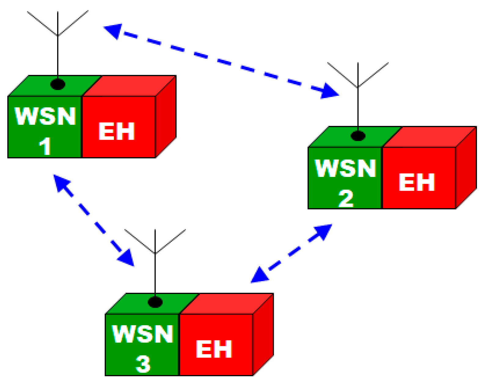
Figure 2.
A typical operation of a thermoelectric harvester.
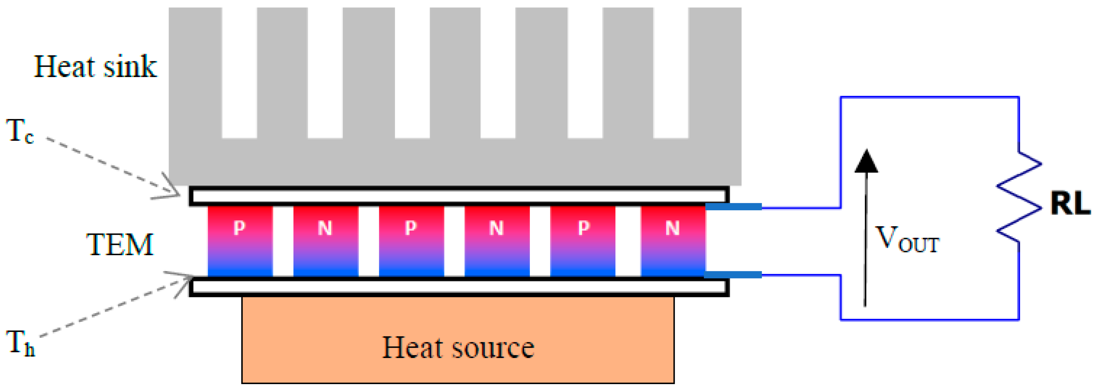
Figure 3.
Layered structure of a thermoelectric generator and corresponding equivalent electrothermal circuit components.
Figure 3.
Layered structure of a thermoelectric generator and corresponding equivalent electrothermal circuit components.
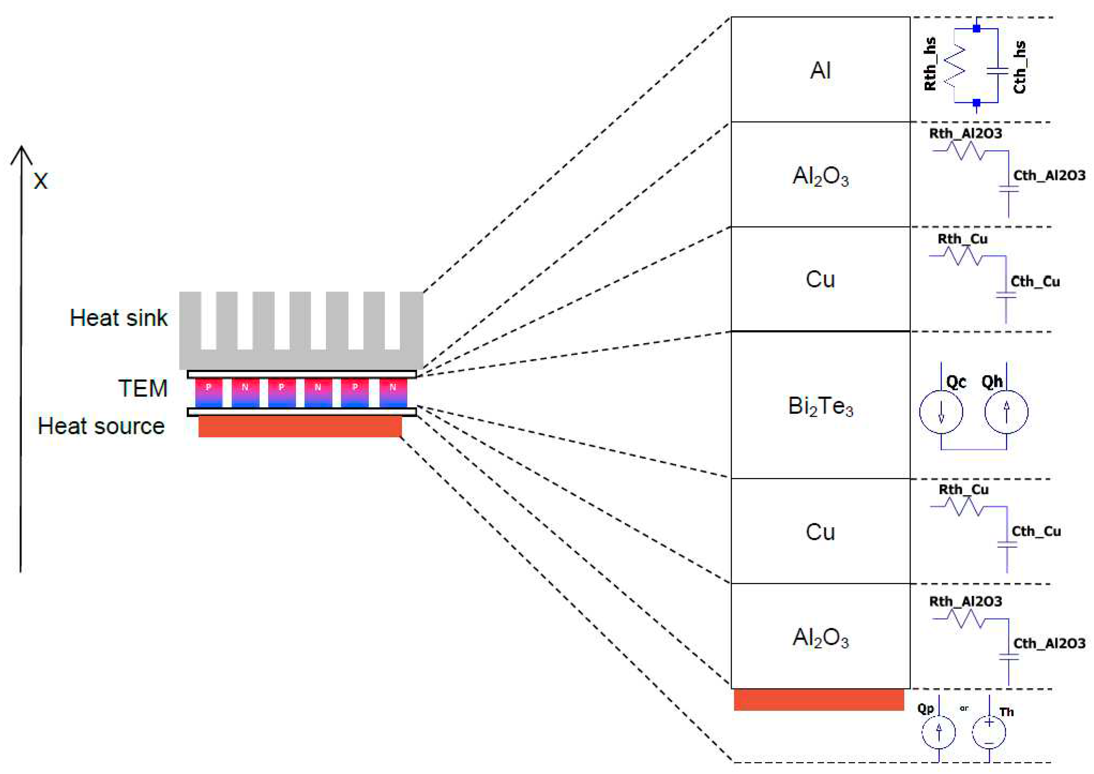
Figure 4.
Linear approximation of the temperature dependence of the total resistance R, Seebeck coefficient S, and thermal conductance K of the TEC1-12706 module.
Figure 4.
Linear approximation of the temperature dependence of the total resistance R, Seebeck coefficient S, and thermal conductance K of the TEC1-12706 module.
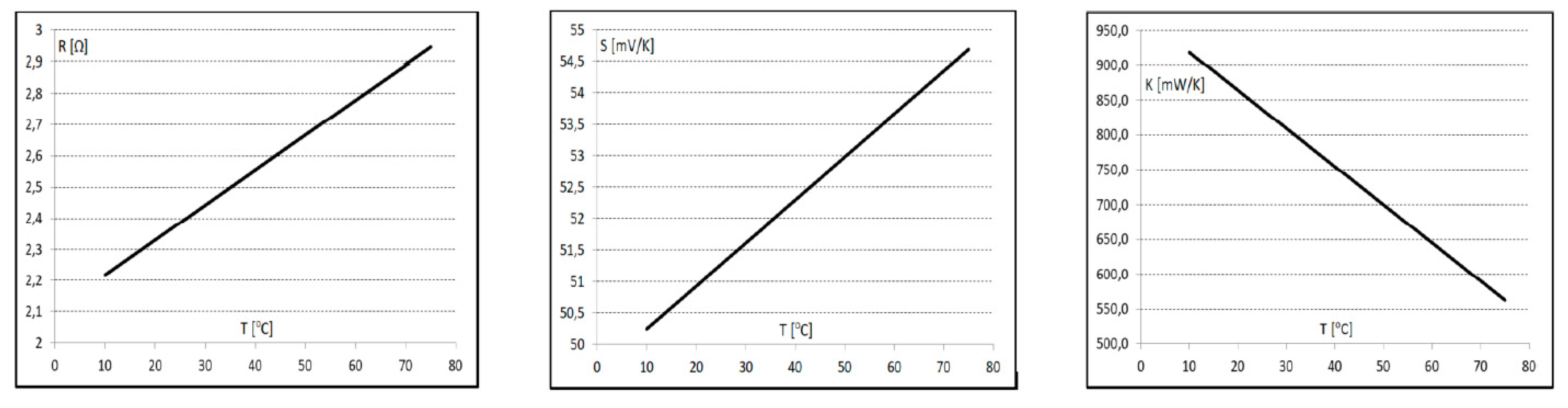
Figure 5.
Equivalent electrothermal model of the thermoelectric converter based on thermoelectric module TEC1-12706.
Figure 5.
Equivalent electrothermal model of the thermoelectric converter based on thermoelectric module TEC1-12706.
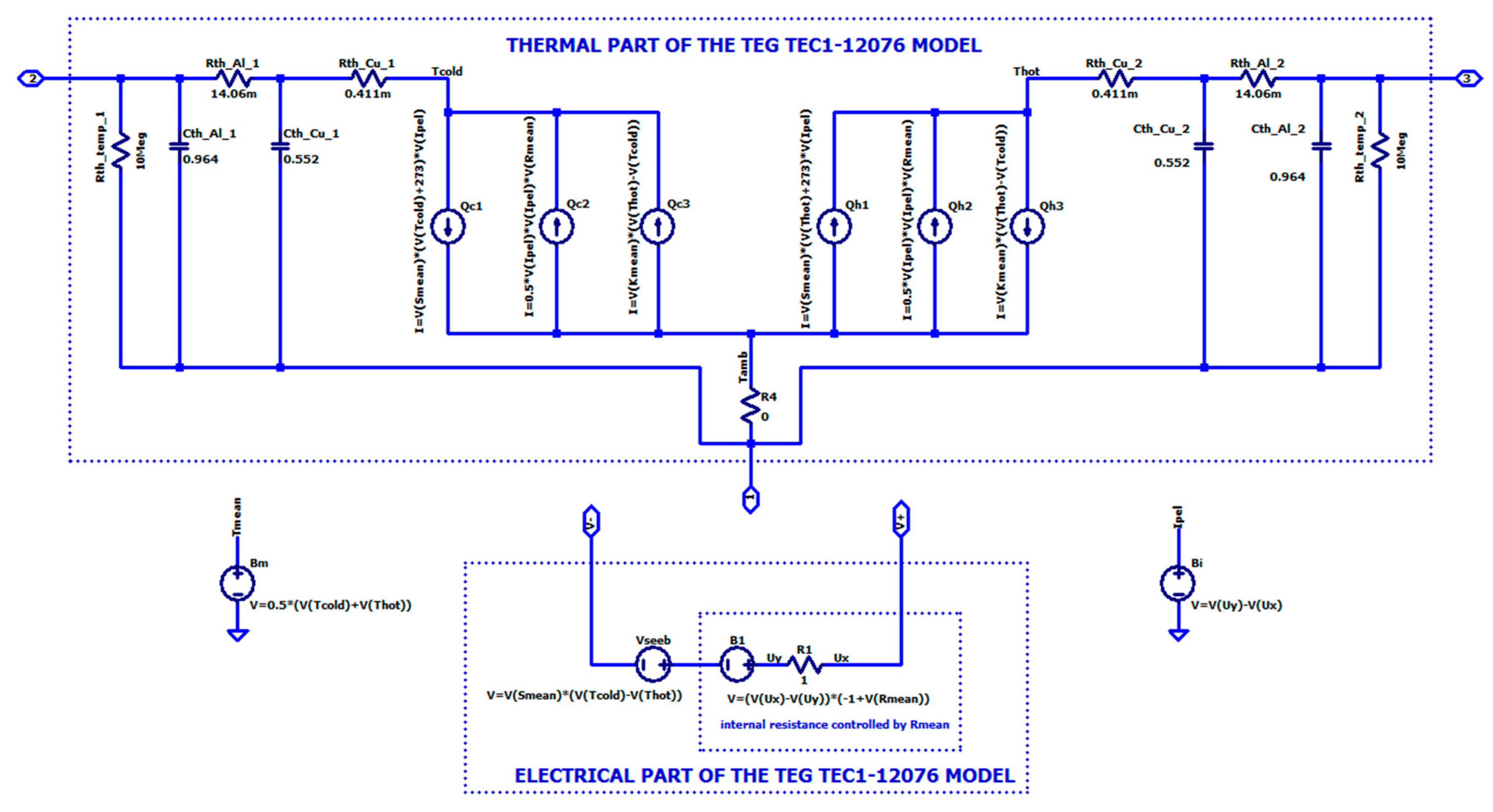
Figure 6.
Description of the heat sources Qcn, Qhn and Seebeck voltage source in LTspice notation.
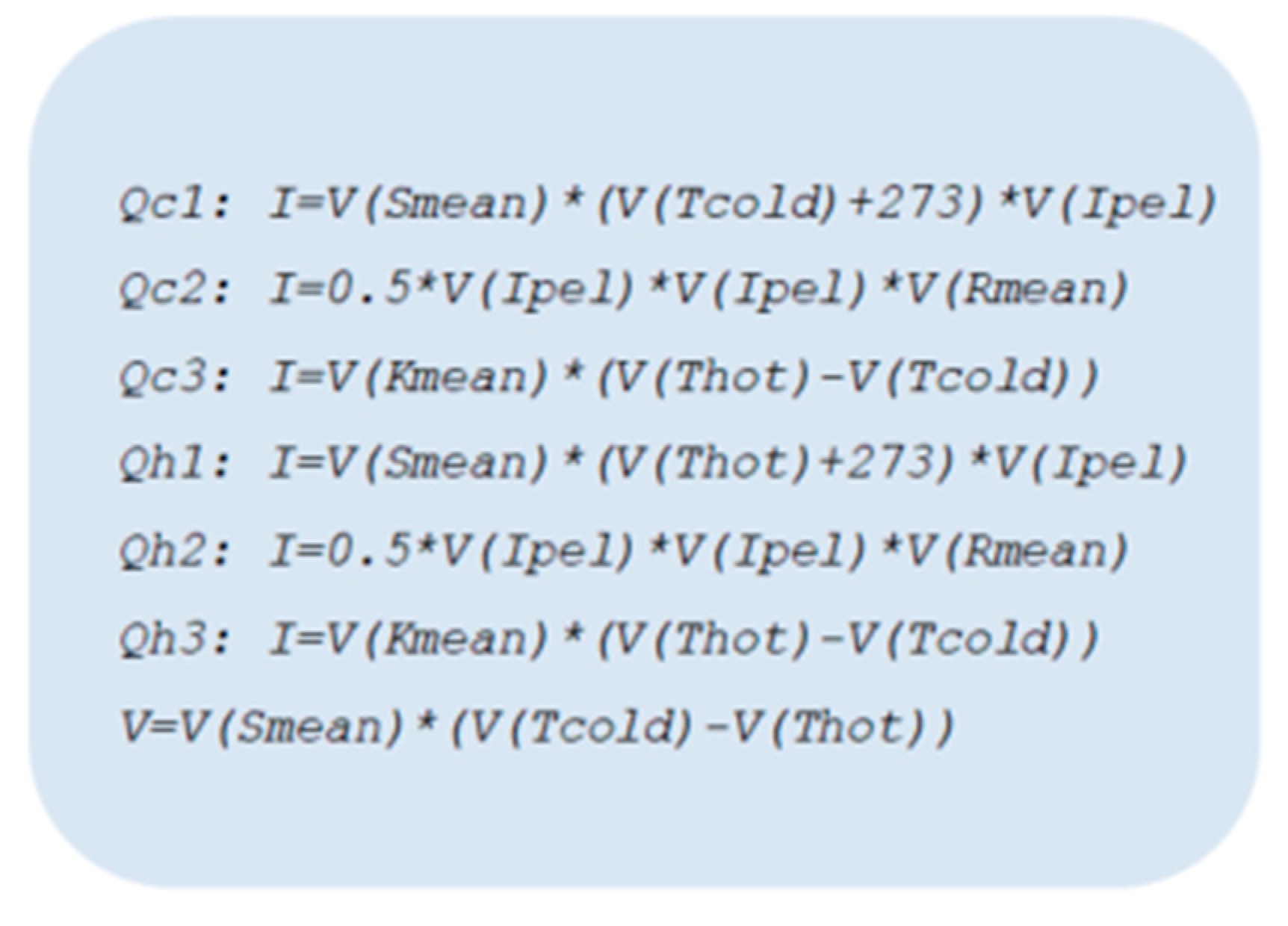
Figure 7.
LTspice symbol of the thermoelectric module TEG TEC1-12706.
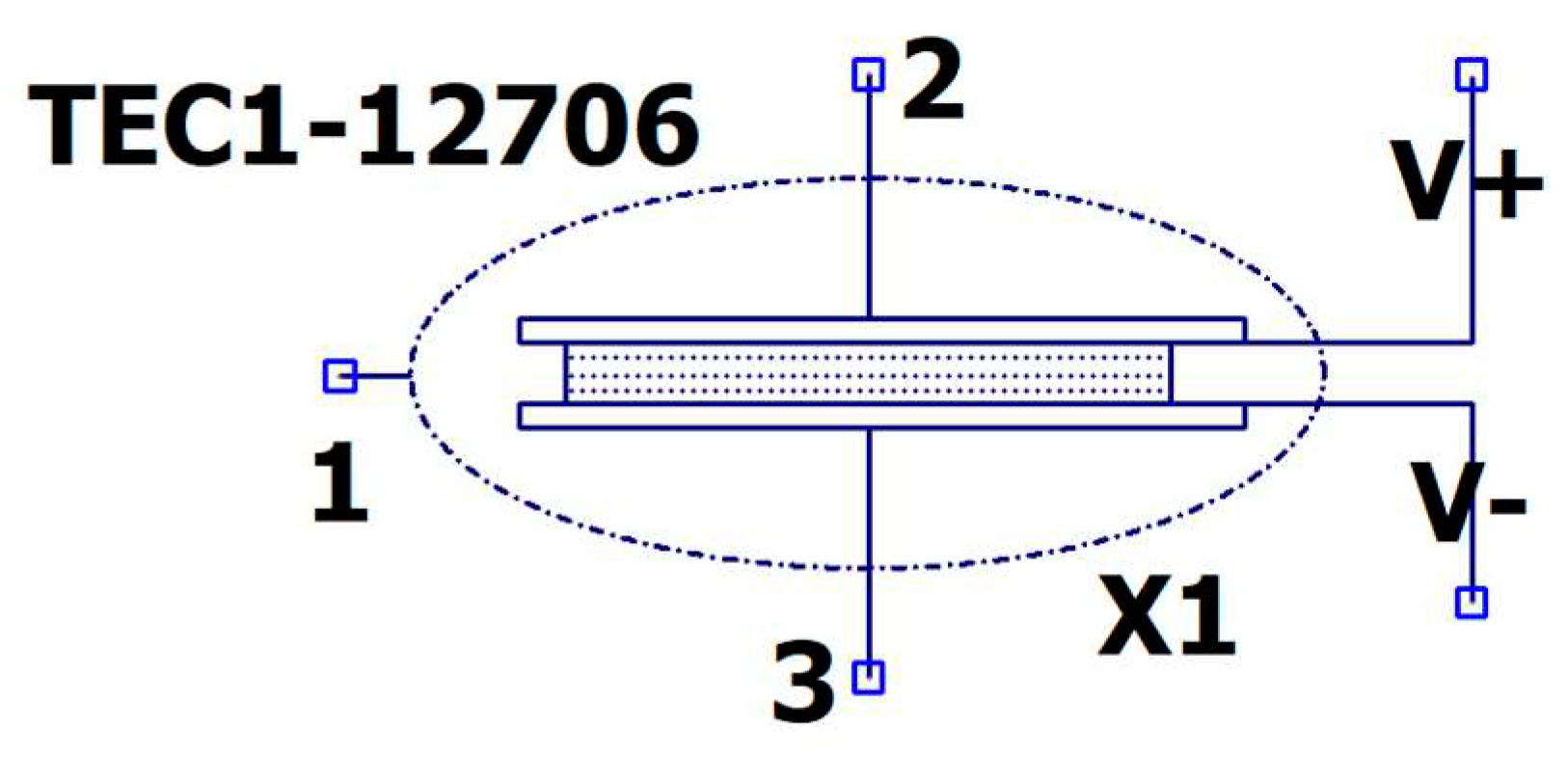
Figure 8.
LTspice circuit modelling changing temperature gradients across TEG and resulting output Seebeck voltage at open circuit.
Figure 8.
LTspice circuit modelling changing temperature gradients across TEG and resulting output Seebeck voltage at open circuit.
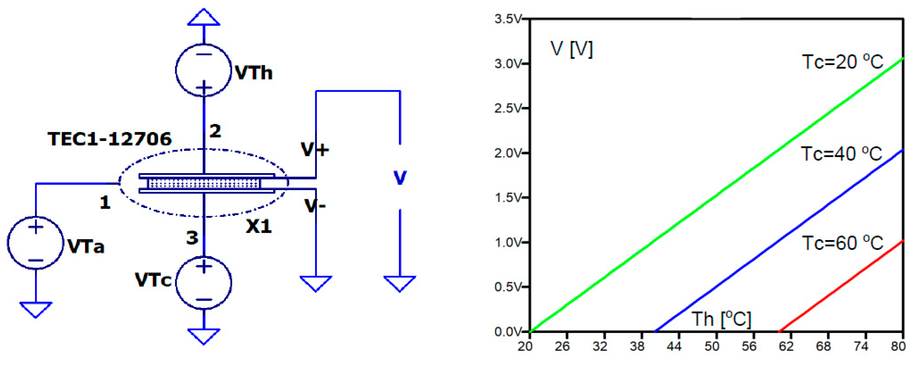
Figure 9.
Output power PL against load current IL at constant Tc=20 oC and changing Th.
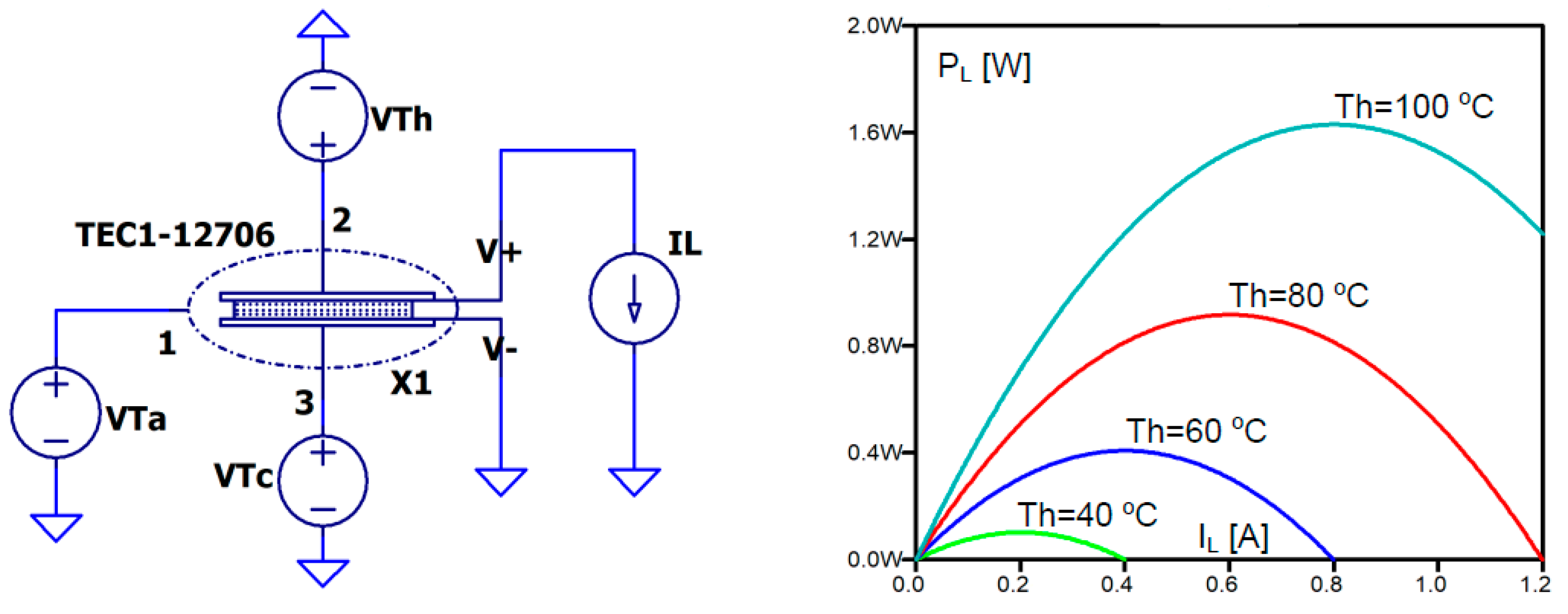
Figure 10.
Output power PL against load resistance RL at constant Tc=20 oC and changing Th.
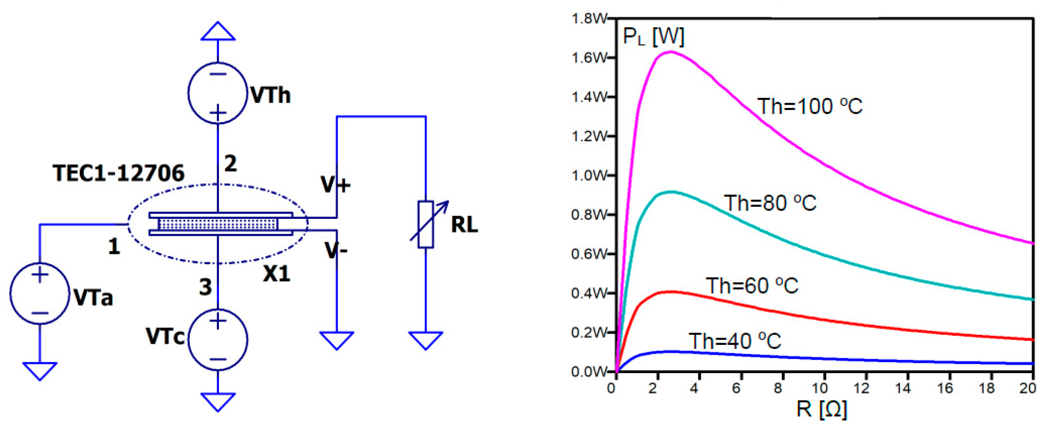
Figure 11.
Output power PL against thermal resistance Rth_heat_sink of a heat sink at matched resistive load RL=2.5 Ω, constant Tc=20 °C and changing Th.
Figure 11.
Output power PL against thermal resistance Rth_heat_sink of a heat sink at matched resistive load RL=2.5 Ω, constant Tc=20 °C and changing Th.
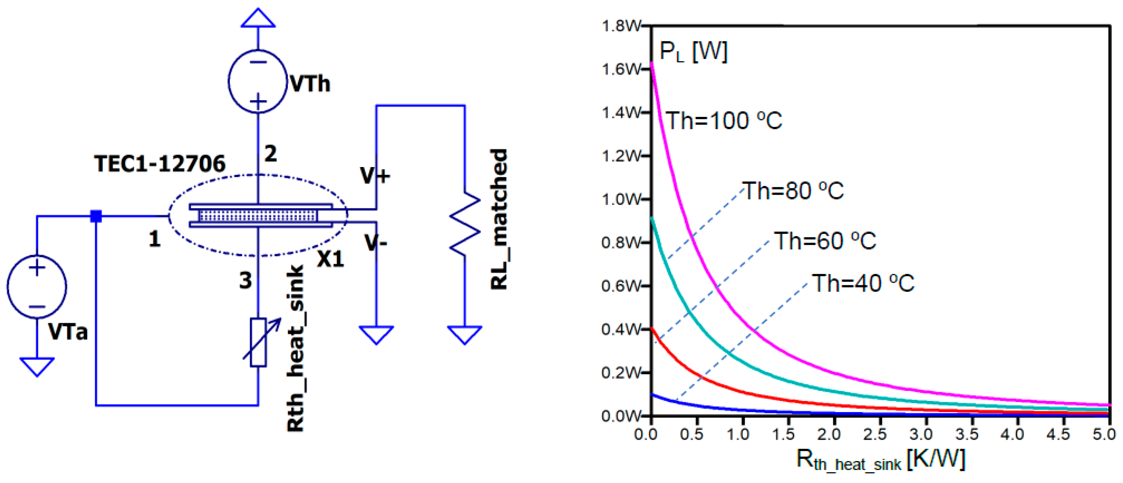
Figure 12.
Combined electrothermal circuit - TEG and LTC3108 - under test (left) and the plot of the output voltage VOUT from the LTC3108 (right) when the temperature gradient across the TEG is 20 °C.
Figure 12.
Combined electrothermal circuit - TEG and LTC3108 - under test (left) and the plot of the output voltage VOUT from the LTC3108 (right) when the temperature gradient across the TEG is 20 °C.
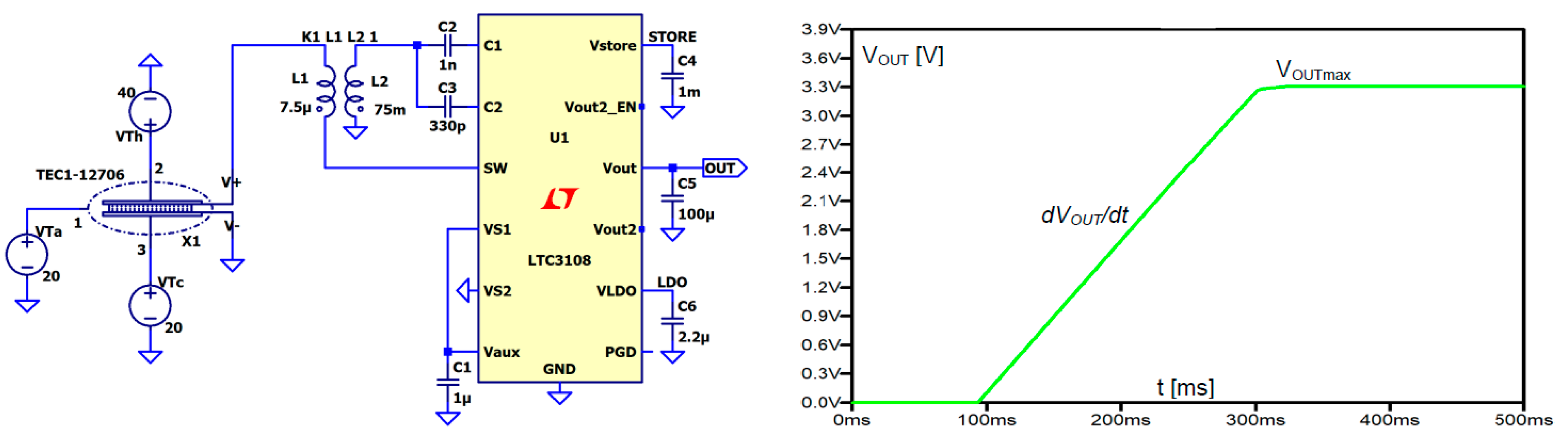
Figure 13.
Maximum output power POUTmax (left) and conversion efficiency coefficient η (right) against temperature difference ∆T across TEG, obtained for a combined TEG-LTC3108 circuit.
Figure 13.
Maximum output power POUTmax (left) and conversion efficiency coefficient η (right) against temperature difference ∆T across TEG, obtained for a combined TEG-LTC3108 circuit.
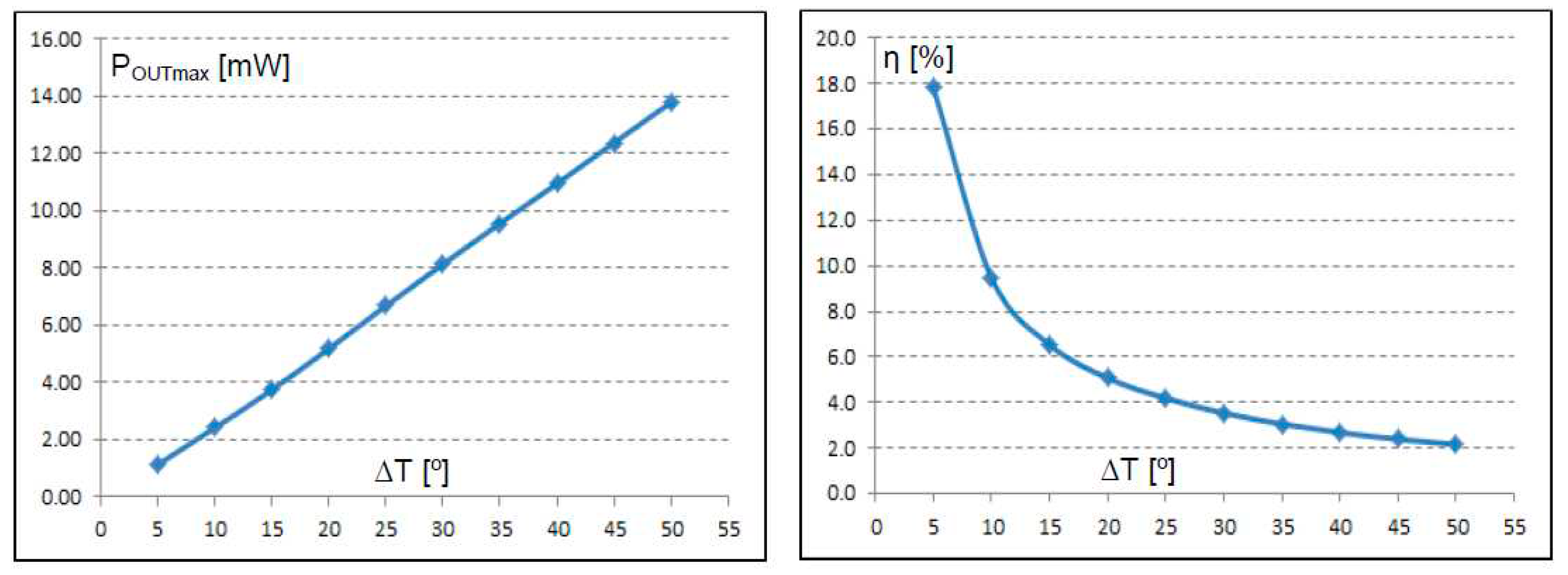
Figure 14.
Autonomous wireless sensor node powered by a TEG.
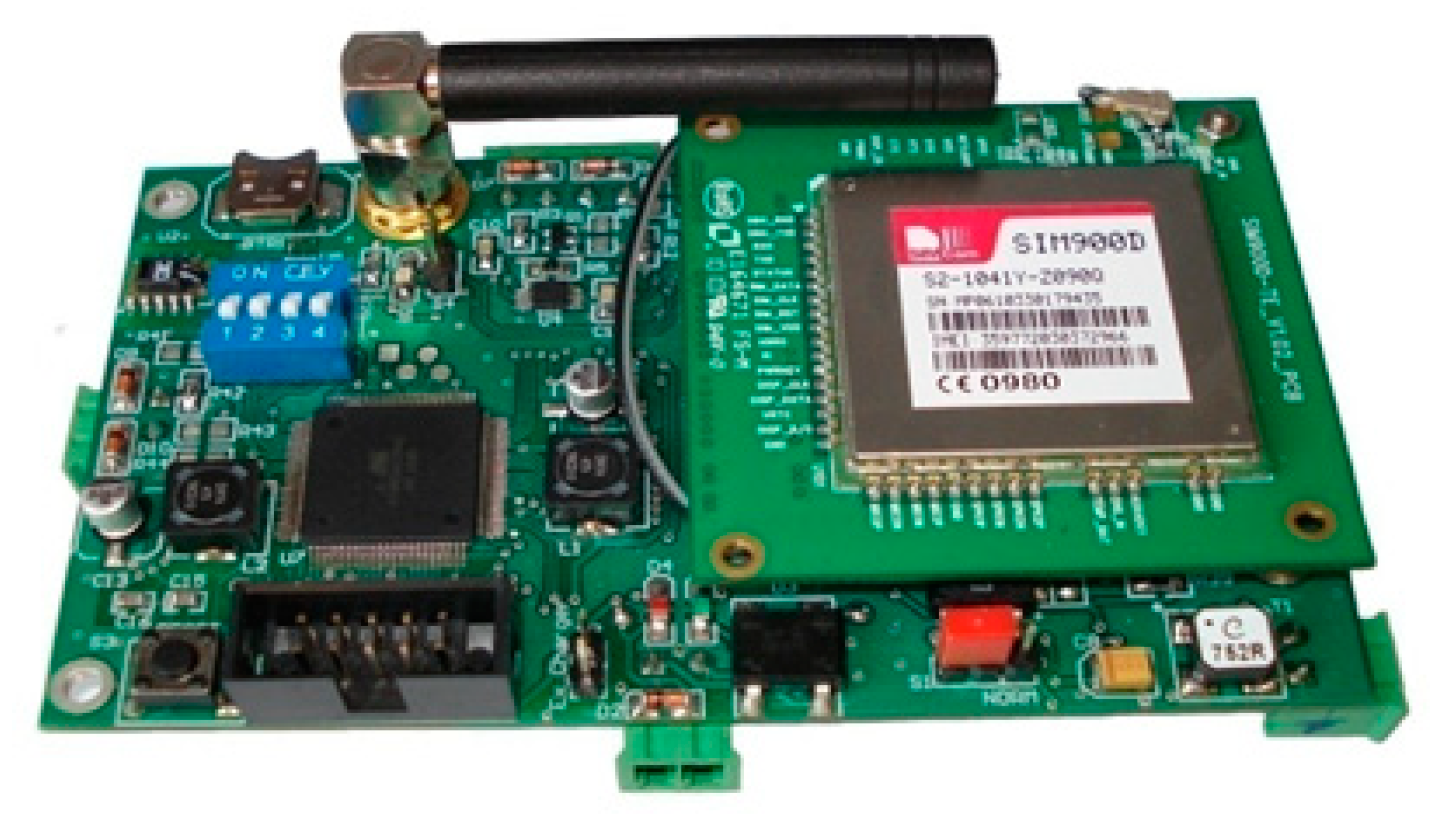
Figure 15.
Output voltages managed by the LTC3108 supplied by the TEG TEC1-12706 subjected to periodic temperature changes Th at the hot side and at constant Tc=20 oC.
Figure 15.
Output voltages managed by the LTC3108 supplied by the TEG TEC1-12706 subjected to periodic temperature changes Th at the hot side and at constant Tc=20 oC.
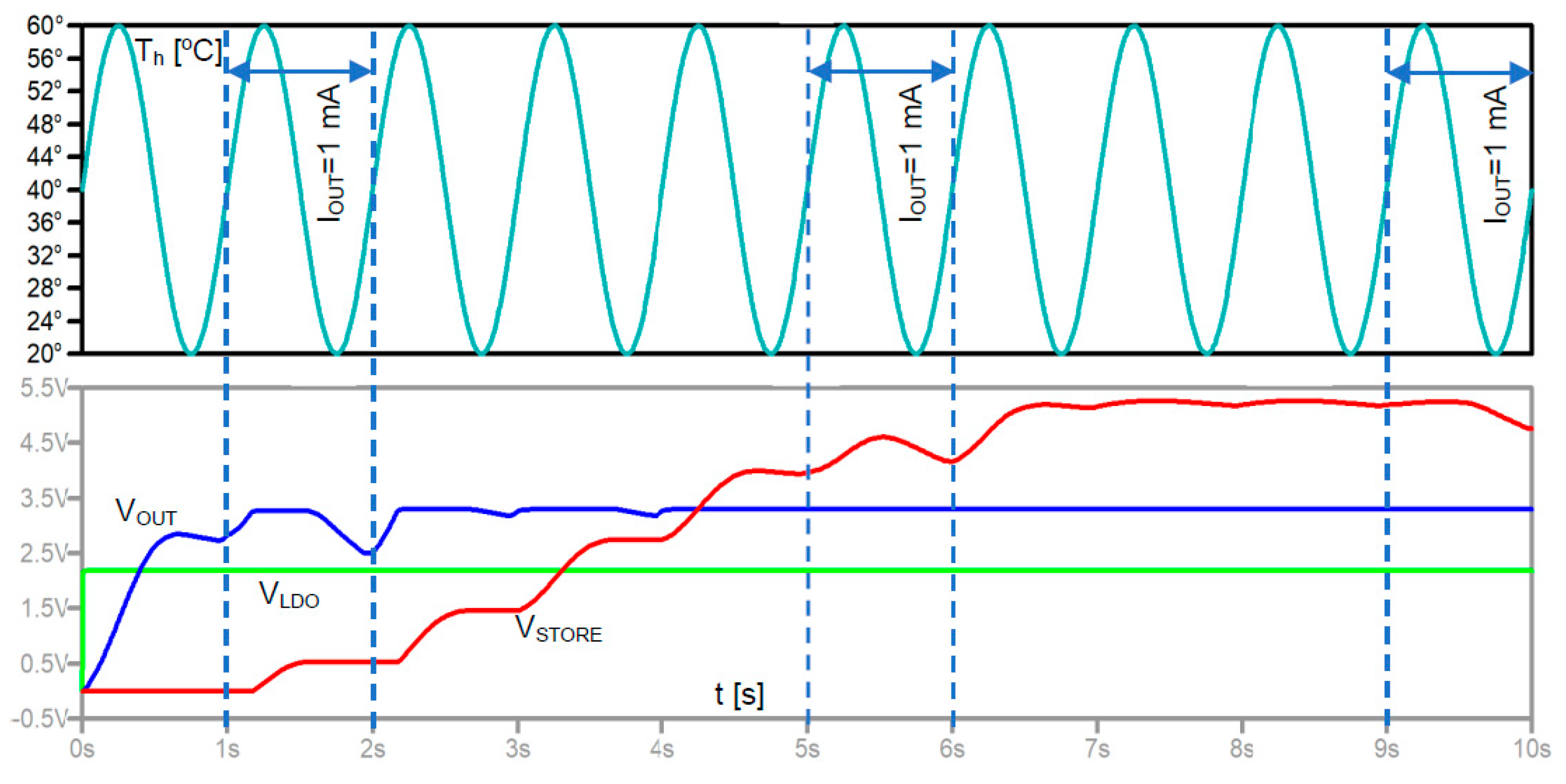
Figure 16.
The concept of pulse mode operation of TEG.
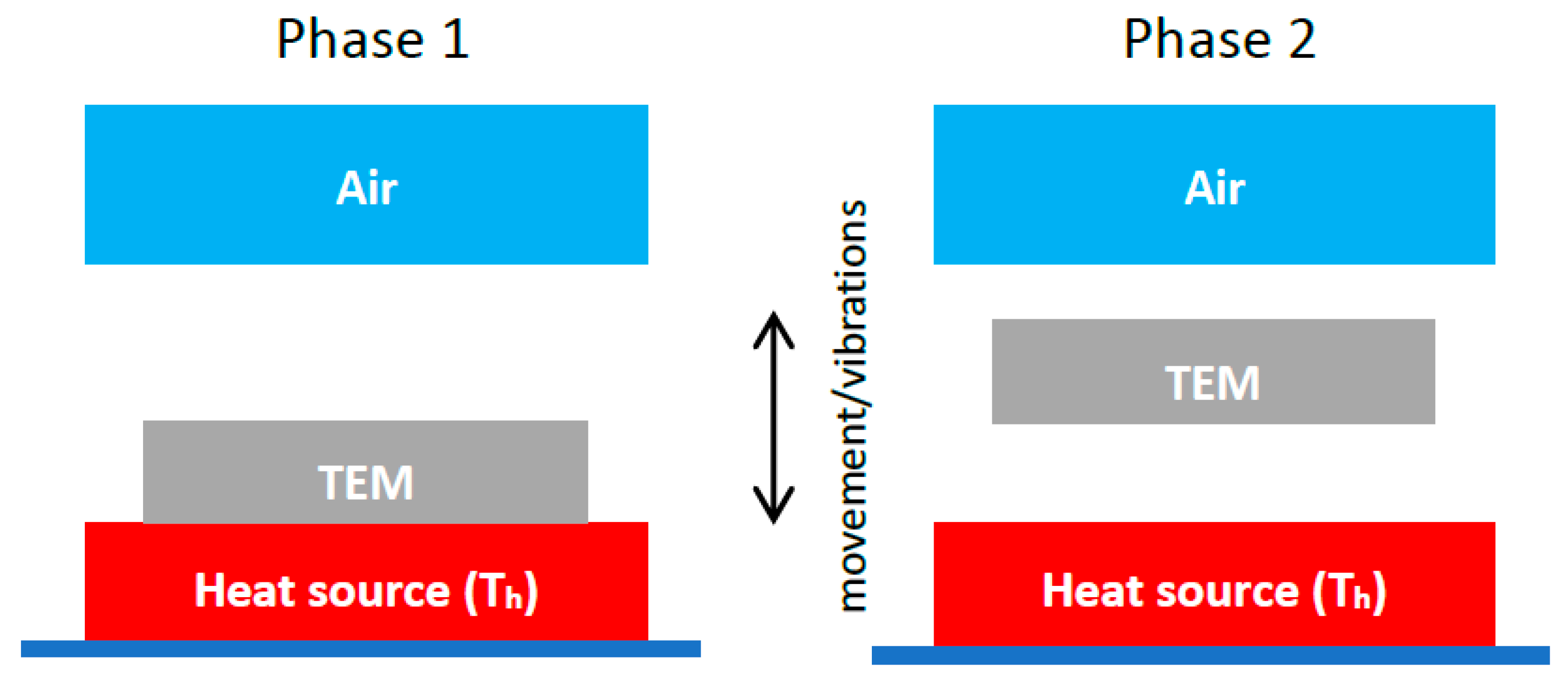
Figure 17.
Equivalent electrothermal circuit demonstrating pulse mode operation of TEG.
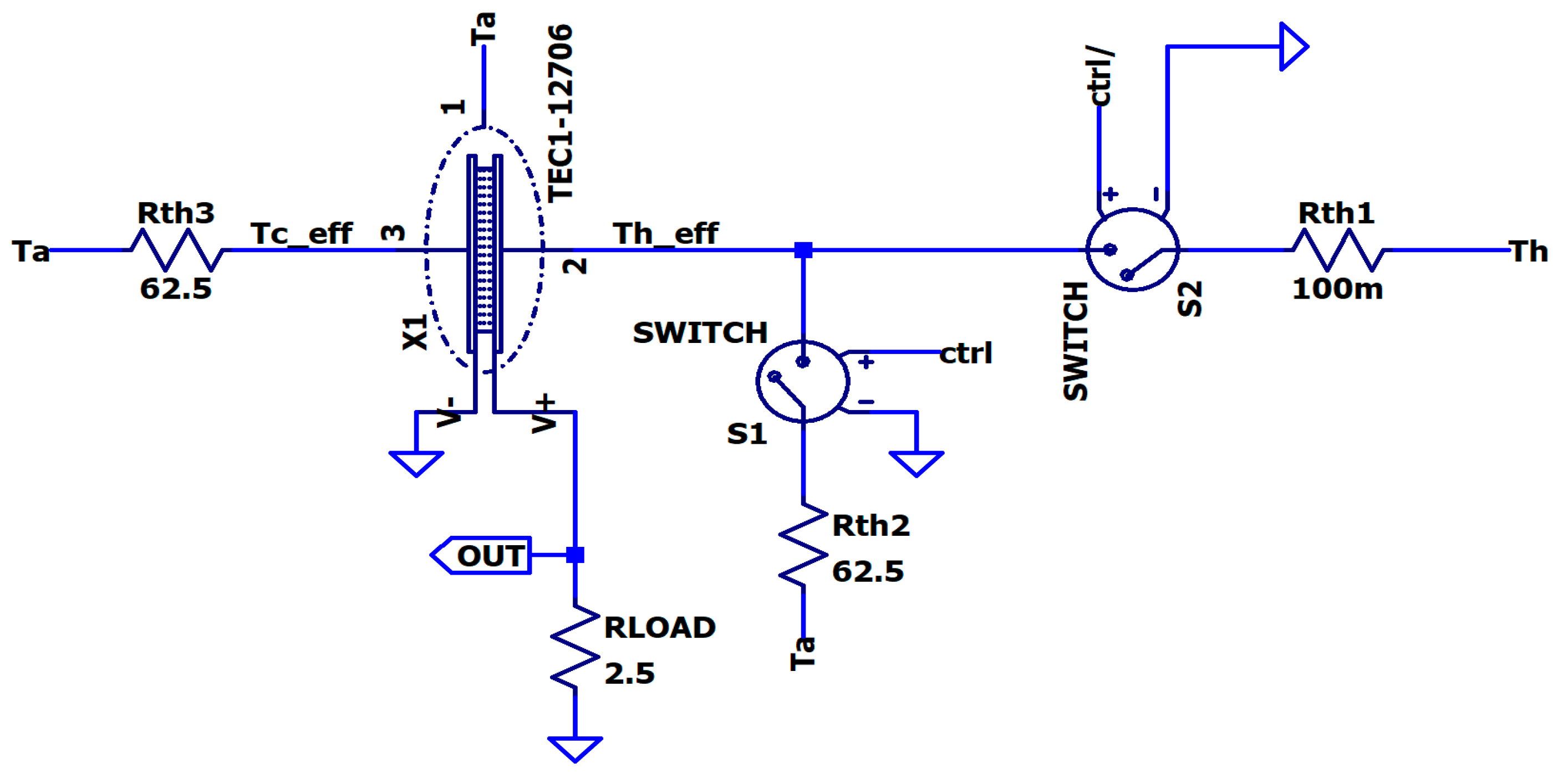
Figure 18.
Effective temperatures Tceff and Theff across the TEG and output power in the transient state and the equilibrium.
Figure 18.
Effective temperatures Tceff and Theff across the TEG and output power in the transient state and the equilibrium.
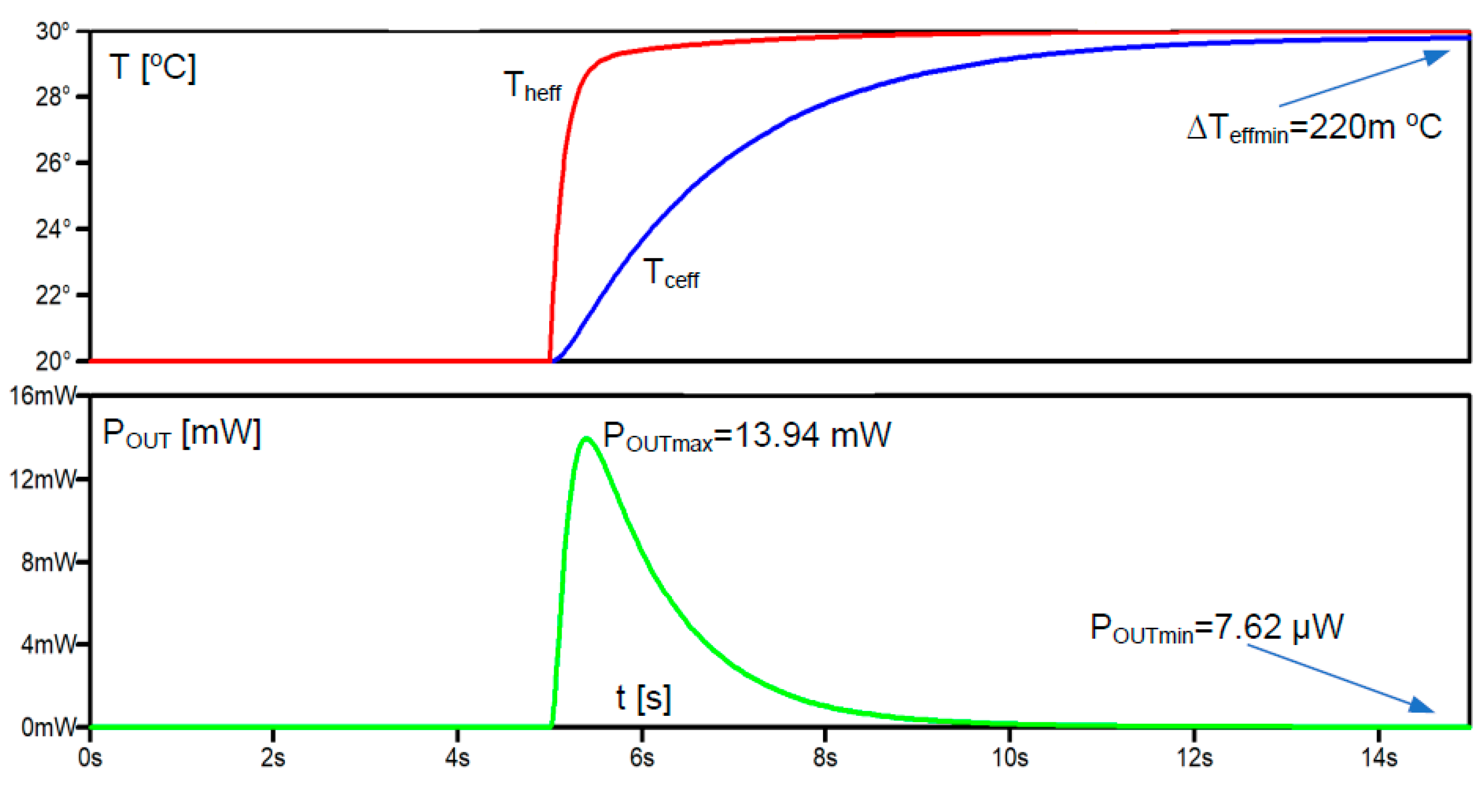
Figure 19.
Numerical simulation of pulse mode operation of TEG (top – control signal, middle – effective temperatures at both sides of the TEG, bottom – output power).
Figure 19.
Numerical simulation of pulse mode operation of TEG (top – control signal, middle – effective temperatures at both sides of the TEG, bottom – output power).
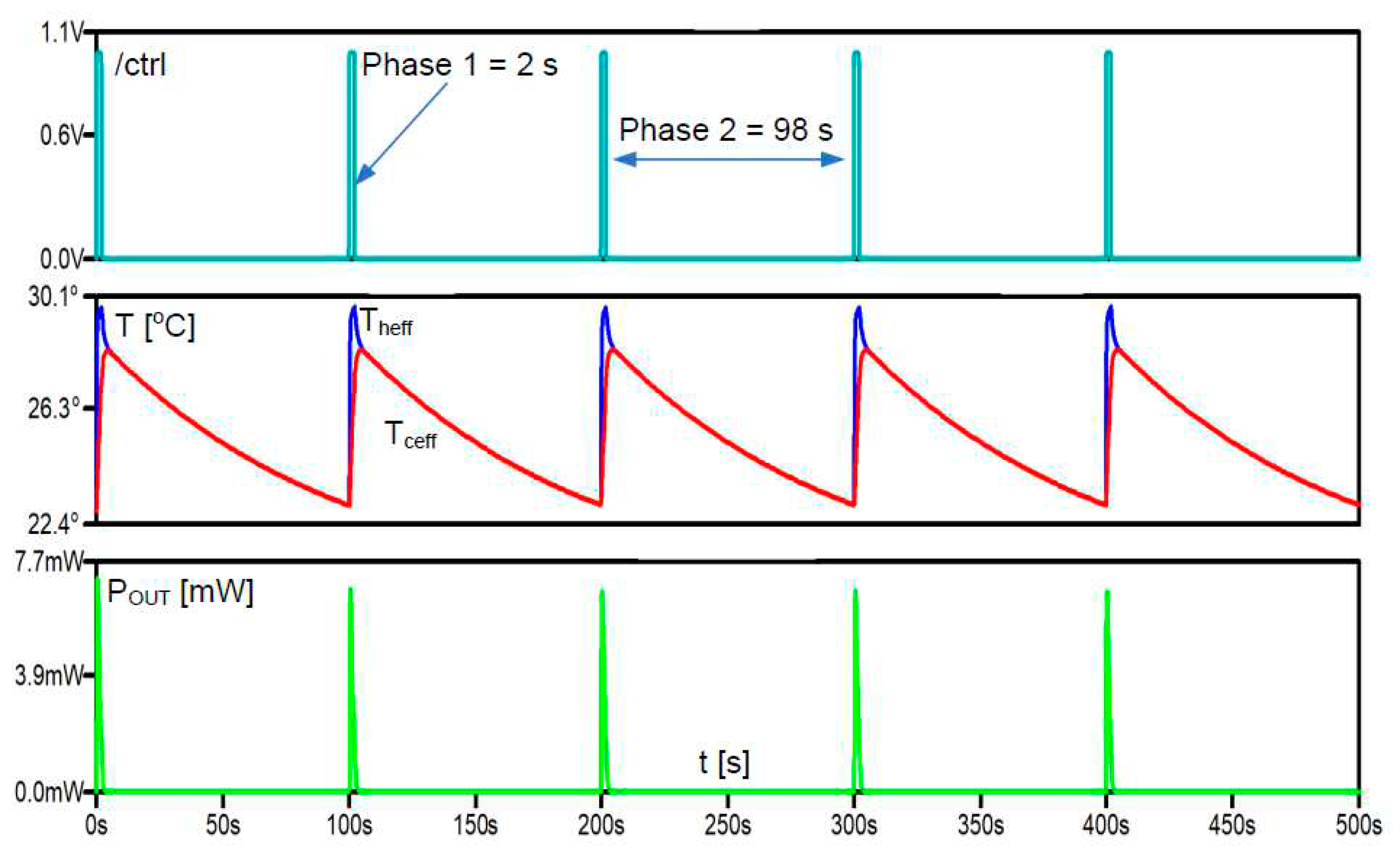
Figure 20.
Average output power POUTavg from TEG working in the pulse mode operation, against the Phase 1 time tPhase1 at constant total period ttotal=tPhase1 + tPhase2 = 100 s and temperature difference between the heat source and the ambient equal to 10 °C.
Figure 20.
Average output power POUTavg from TEG working in the pulse mode operation, against the Phase 1 time tPhase1 at constant total period ttotal=tPhase1 + tPhase2 = 100 s and temperature difference between the heat source and the ambient equal to 10 °C.
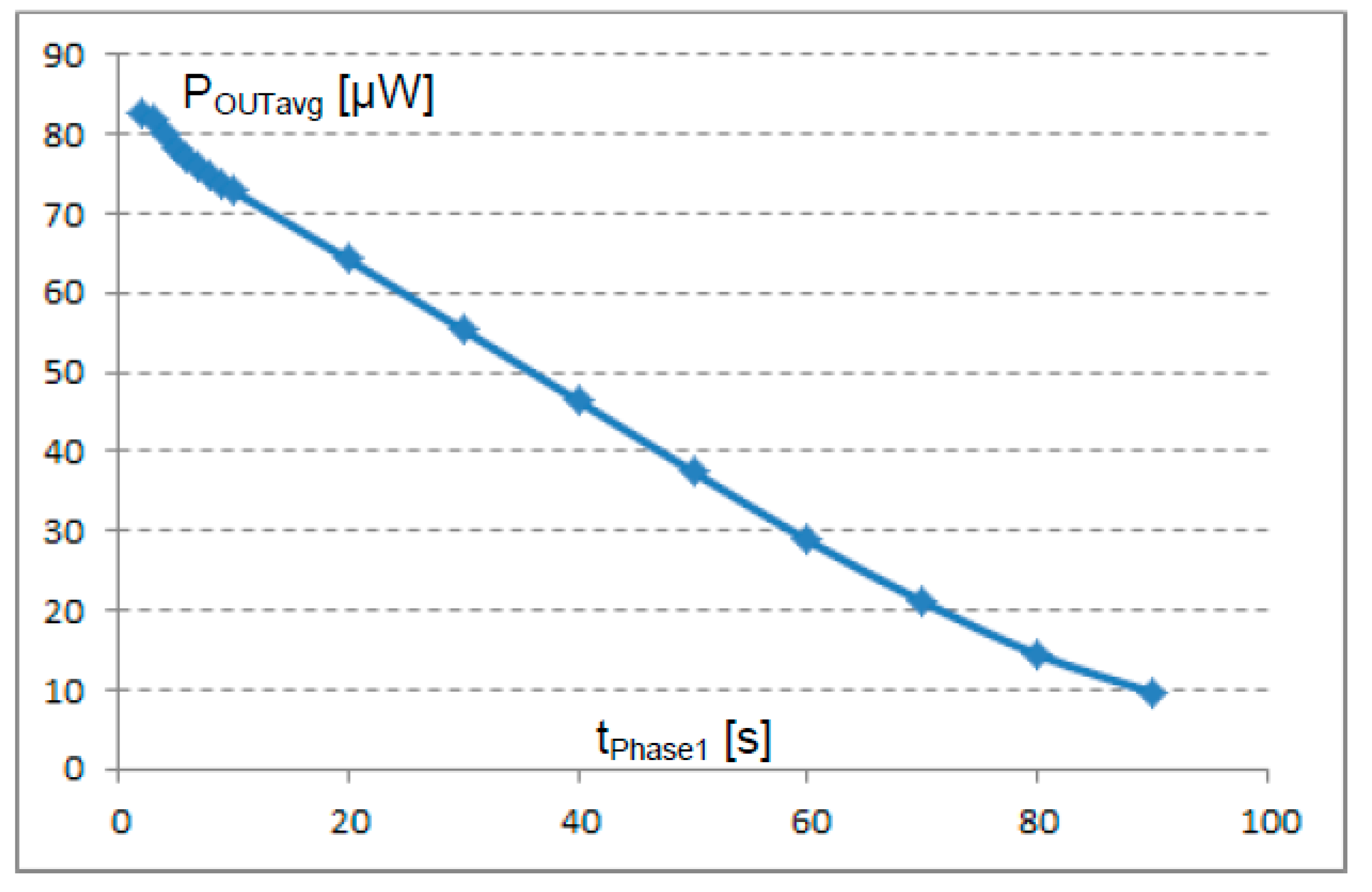
Table 1.
Values of the extracted thermal components parameters of TEC1-12706 module used in the equivalent circuit model.
Table 1.
Values of the extracted thermal components parameters of TEC1-12706 module used in the equivalent circuit model.
| Rth_Cu [K/W] |
Cth_Cu [J/K] |
Rth_Al2O3 [K/W] |
Cth_Al2O3 [J/K] |
R [Ω] |
S [mV/K] |
K [mW/K] |
|||
|---|---|---|---|---|---|---|---|---|---|
| a | b | a | b | a | b | ||||
| 0.41m | 0.55 | 14.06m | 0.96 | 0.011 | 2.106 | 0.068 | 49.56 | -5.48 | 973.9 |
Disclaimer/Publisher’s Note: The statements, opinions and data contained in all publications are solely those of the individual author(s) and contributor(s) and not of MDPI and/or the editor(s). MDPI and/or the editor(s) disclaim responsibility for any injury to people or property resulting from any ideas, methods, instructions or products referred to in the content. |
© 2023 by the authors. Licensee MDPI, Basel, Switzerland. This article is an open access article distributed under the terms and conditions of the Creative Commons Attribution (CC BY) license (http://creativecommons.org/licenses/by/4.0/).
Copyright: This open access article is published under a Creative Commons CC BY 4.0 license, which permit the free download, distribution, and reuse, provided that the author and preprint are cited in any reuse.


