
Submitted:
15 November 2023
Posted:
16 November 2023
You are already at the latest version
Abstract
This paper investigates if the polar groups induced by a plasma treatment can increase the lap shear strength of laser joined metal and plastic hybrids. Optimal laser joining parameters for cold-rolled AISI304 – Polyamide 6.6 and sandblasted AISI304 - Polypropylene hybrids are developed. The OWRK-method was utilized to identify the change in surface free energy of a low-pressure plasma treatment. Plasma treated samples were joined and tested. The fractured surfaces were investigated via light microscopy and SEM. The arithmetic means of the plasma treated hybrids lap shear strength with polyamide 6.6 varied slightly but all measured values were within the range of the untreated samples. The lap shear strengths of the polypropylene hybrids were significantly reduced. This was attributed to an overaging and the development of low molecular weight oxidized materials which lead to a weak boundary layer. No correlation between surface free energy and the lap shear strength could be found.
Keywords:
Plastic-metal hybrid
; laser joining
; Surface free energy
; Low-pressure plasma
; OWRK-method
; Polyamide 6.6
; Polypropylene
; AISI 304
; Joining process
; Dissimilar joining
1. Introduction
The combination of metals and plastics enables high strength and lightweight structures by combining the low density, corrosion, and oxidation resistance of plastics with the extraordinary mechanical properties of metals. Common joining technologies for plastic-metal hybrids are mechanical joining processes [1,2,3], adhesive bonding [4,5,6] and direct thermal joining. Among the thermal joining methods, next to induction [7] or ultrasound [8], lasers can be used to join metals to thermoplastics [9,10,11]. Due to the high-efficient and non-contact energy input via laser, this field of research got high attention in direct thermal joining processes.
Kawahito et al. were the first research group who investigated the application of Lasers in 2006 and defined the term laser-assisted metal and plastic (LAMP) joining. They used different types of lasers to join AISI 304 with amorphous polyamide, polyethylene terephthalate, polycarbonate, and polypropylene with at least 80% transmissivity. With polypropylene as exception, sound joints were created [12]. The joints can be bonded by direct or indirect measures. During the direct method the laser is transmitted through the thermoplastic heating the interface between polymer and metal [13]. Indirectly the laser heats the backside of the metal, transferring the heat through the cross section of the metal substrate via heat transfer. In both cases the polymer plasticizes and wets the metal substrate [14]. The schematic of these joining processes is shown in Figure 1. Pressure during the joining process is necessary to ensure a good contact between the metal surface and the molten plastic.
To improve the bonding strength, different kinds of surface pretreatments were investigated. Some research groups used laser ablation to create grooves in the metal substrate to improve the mechanical adhesion. Schricker et al. could increase the tensile strength of a AISI 304 – polyamide 6 from 2.1 MPa to 11.3 MPa by laser structuring the steel surface [15]. Furthermore, other investigations revealed, that additional adhesion theories next to the mechanical adhesion occurred in laser joined metal and plastic hybrids. XPS measurements showed, that a chemical bond between polyamide and AISI 304 existed due to increased peaks of chromium and oxygen indicating the creation of chromium oxide [12]. Katayama and Kawahito identified a possible chemical bond between the chromium oxide layer of an AISI 304 steel with elements of the used polyethylene terephthalate in their laser joined hybrids [16]. Hirchenhahn et al. created aluminum-polyamide 6.6 hybrids via laser joining. They identified that the chemical bond formed was a carbon-oxygen-aluminum bond. One of the possible reaction sides is the double oxygen bond of the amide group in the polyamide 6.6. This indicates that polymers with polar groups like polyamide 6.6 are capable of creating chemical bonds at the interface [17,18]. Al-Sayyad et al. used a low-pressure plasma treatment before joining aluminium and polyamide by means of indirect laser joining. They used a mixture of oxygen and nitrogen as plasma gas. The shear load increased when the polyamide or the aluminium was treated and maximized with a treatment of both surfaces. The rise in shear resistance correlated with the rise in surface free energy. This research leads to the hypothesis, that the thermodynamic theory of adhesion and the surface free energy correlates with the lap shear strength of laser joined metal and plastic hybrids [19].
As mentioned before Kawahito et al. used also polypropylene for their first experiments. No sound joints could be created, resulting in a lap shear strength of zero [16]. Schricker et al. used also polypropylene for their investigation. Without the laser ablation process of the metal substrate no sound joint could be created. With the improved mechanical adhesion, the shear strength increased from zero to 8.7 MPa [15]. In adhesive technologies surface treatments of plastics without polar groups like polypropylene is common to increase the joint strength. Low-pressure plasma treatments are used to clean and activate the surface increasing their surface free energy significantly by producing polar groups and radicals on the surface [20]. C. Mandolfino treated the surface of polypropylene with a low-pressure plasma treatment before using an adhesive. A treatment in an oxygen plasma for 180 s increased the lap shear strength by 387 % from 0.56 MPa to 2.72 [21].
This research investigates the influence of a low-pressure plasma treatment on the lap shear strength of laser joined hybrids with AISI 304, polyamide 6.6 and polypropylene. Oxygen, water vapor and argon were utilized as reactive working gases. While oxygen and water vapor plasma create radicals and add functional groups, argon as an inert gas only establishes radicals on the polymeric surface [20] (p 25). The surface free energy is measured by the OWRK – method and correlated between the results for the lap shear strength. Additionally, the fractured surfaces are analyzed to identify possible residue due to increased covalent bonds due to the low-pressure plasma treatment.
2. Materials and Methods
2.1. Materials
The plastics used in this research were semi crystalline polyamide 6.6 and amorphous polypropylene. These were chosen due to the polar amino group of polyamide 6.6 and the lack of any polar group in polypropylene. Figure 2 shows the chemical structure of both plastics and the polar amino group of polyamide 6.6.
As metal substrate the cold-rolled steel AISI 304 (DIN 1.4301, ISO X5CrNi18-10) was chosen. For the hybrids with polyamide the cold rolled surface was used, while the surface of the steel was sand blasted for the hybrids with polypropylene. This was done because untreated polypropylene needs sufficient mechanical adhesion to create sound joints. The parameter set was utilized to identify the change due to the low-pressure plasma treatment. The sand blasting increased the surface roughness of the steel, which was analyzed with five measurements of a T1000 Hommeltester. The average surface roughness is shown in Table 1.
An MHG SMG 50 was utilized for the sand blasting. White corundum with a granularity varying between 150 and 212 µm, an air pressure of 4 bar at an angle of 90° with a distance between steel and blasting pistol of 50 mm was used in the process. The geometry of both materials was 50 mm x 25 mm x 2 mm. Prior to the joining process the surfaces were cleaned with ethanol.
2.2. Laser setup
A fiber laser with a maximum continuous laser power output of 250 W and a wavelength of 1080 ± 5 nm was used. The laser was mounted with a collimation unit, a beam expander and a galvanometric scanner in a constructed mount seen in Figure 3 (a). A f-theta lens ensured an orthogonal laser beam over the whole scanning area.
A specimen holder for three joints with an overlap width of 12.5 mm and an applied pressure of 0.4 MPa by compression springs was utilized shown in Figure 3 (b). The distance between the sample surface and the f-theta lens was kept constant to ensure a laser spot diameter of 5 mm. A simple line was used as travelling geometry. To ensure a homogeneous heating additional 5 mm before and after the first and last sample were added. The indirect heating method was utilized for all samples. The variation in laser power and scanning speed are shown in Table 2. To achieve a better comparison to other LAMP publications the laser power was divided by the scanning speed to achieve the energy input per unit length also known as line energy. These parameters were utilized to identify the parameters with the maximum lap shear strength with an adhesive failure mode.
2.3. Low-pressure plasma setup
A low-pressure plasma system SmartPlasma2 by plasma technology GmbH was utilized for the surface treatment of the plastics. Argon, water vapor and oxygen were used as working gases. To initiate the low-pressure plasma a vacuum pump reduced the chamber pressure to 0.05 mbar. The respective working gas was lead in to achieve the working pressure. This is a continuous process between pumping and gas inlet to ensure a steady working pressure. The working pressure was used at a fixed value of 0.1 mbar. The generator with the low frequency of 20 to 50 kHz at a power level of 80 W was used to create the plasma. The plastic substrates were exposed to the plasma for 10 s, 180 s and 600 s.
2.4. Contact angle and surface free energy measurement
To identify the surface free energy changes due to the plasma treatment the method of Owens, Wendt, Rabel and Kaelble (OWRK-method) was utilized. They used the geometric mean value to combine polar and dispersive components to develop the following equation.
is the surface tension of the liquid, is the surface tension of the solid and is the contact angle between liquid, surface, and atmosphere. The superscripted letter indicates the polar or disperse component. At least two liquids with known surface tensions are required to calculate the surface free energy via the OWRK-method. One of these liquids needs to have a polar component of or near zero. In this research demineralized water and diiodomethane were utilized. The polar and disperse values used in this research are shown in Table 3 [22].
Up to 5 µl water and 3 µl diiodomethane were deposited each on the surface by a micro syringe. Ten readings for each test liquid were taken at different locations on the treated surface. The ImageJ plugin for contact angles was utilized to identify the values of the different readings. The mean wetting angle of diiodomethane were utilized to calculate the disperse component of the surface free energy. With the value of the disperse component and the wetting angle of water the total surface free energy of the surface could be obtained.
2.5. Mechanical testing and microstructural analysis
The lap shear tests were performed with an Instron E10000 with a test speed of 0.5 mm min-1. Spacers were attached at each end of the lap shear samples to assure a parallel load. The fixation of the samples in the test setup is shown in Figure 4.
Five samples were tested for each parameter set. ImageJ and a macroscope were used to determine the wetted area of the samples. Additionally, a Leica DVM6 and the associated software Leica Application Suite X (Las X) was used to identify the heat affected zone.
To identify residue of the plastics on the metal samples a scanning electron microscope (REM) was utilized. The JSM 7001F from the Jeol GmbH is equipped with a secondary electron (ETD), backscatter electron (BSE) and energy dispersive x-ray (EDS) detectors.
3. Results and Discussion
3.1. Identification of the joining parameters
To achieve sound joints between the plastic and metal parts distinctive temperature-time profiles need to be found. These depend on the beam power, intensity, used materials and the joint geometry when using the indirect joining method. An optimal parameter set needs to be identified in which the molten plastic wets the metal but does not thermally degrade to a point where the plastic will be significantly damaged. Extensive thermal input can lead to a cohesive failure mode of the plastic part [23]. It is essential to find a set of parameters where the joints have an adhesive failure mode to identify the influence of the low-pressure plasma treatment on the lap shear strength. So, the criteria for choosing the optimal parameter set are the maximum lap shear strength in combination with an adhesive failure section may be divided by subheadings. It should provide a concise and precise description of the experimental results, their interpretation, as well as the experimental conclusions that can be drawn.
Figure 5 shows the lap shear strength of the cold rolled AISI 304 hybrids joined with polyamide by the indirect joining method. Below a line energy of 150 J mm-1 the joints achieve barely a measurable lap shear strength. Some of the samples failed prior to testing. At a line energy of 158 J mm-1 sound joints could be created. Above this value rising cohesive failure occurred. The number of cohesively failed samples rose from 2 at 158 J mm-1 to 5 at 250 J mm-1. It is to mention, that there is a high spread between the measured lap shear strength values at all line energies with the exception of 150 J mm-1 and 166 J mm-1. The whisker of the chosen parameter at 158 J mm-1 have a range of ca. 3 MPa. A cross-section of a sample joined at the chosen parameter is shown in Figure 6.
The Polyamide 6.6 is shown on top while the steel is on the bottom vice versa to the joining configuration. The joining process had no influence on the steel side of the hybrid. On the plastic side on the other hand different interaction happened. At the interface to the steel there are some voids. These voids can be either due to the vaporization of the water content of the polyamide 6.6 or due to thermal degradation. Additionally, the heat affected zone is visible due to a slightly brighter curve. This curve overlaps on the right side of the joined area. On the top right side of the steel sample some molten plastic is visible which was pressed out of the overlap area during the joining process. The investigation of the cross-section shows a good wetting from the polyamide 6.6 melt on the steel. On the other Hand, the created voids can reduce the lap shear strength because they can function as inner notches.
In Figure 6 a) an adhesively failed Polyamide 6.6 – cold rolled AISI 304 hybrid and in Figure 6 b) a cohesively failed sample at a higher line energy is shown. The hypothesis is that with higher line energy the thermal damage increases which leads to a weakened plastic sample. This is also explained by the number of cohesively failed samples. At the line energy of 166 J mm-1 only two of the five tested samples failed cohesively while at 250 J mm-1 every sample failed within the plastic. Also, the fraction of the plastic residue on the overlap joint increases, which can also lead to higher ratio of cohesive failure.
The adhesively failed samples show plastic residues on the steel surface. This residue indicates chemical bonds between the polar groups and the oxides on the steel surface described in the introduction. At line energies below 158 J mm-1 only smaller areas or no residue at all were identified on the steel samples. This indicates that a certain amount of thermal energy is needed to create these chemical bonds.
To investigate the plastic residue further a lap sheared sample was investigated by SEM analysis shown in Figure 7. The sample was cleaned in an ultrasonic bath with ethanol to clear the surface from loose particles. Figure 7 (a) shows the boundary between the residue and the steel surface. The plastic residue was stretched out in the direction of the lap shear test which indicates some form of ductility. Additionally, in Figure 7 (b) the surface of the steel at a higher magnification is shown. Plastic residue is found in between the flattened grains by the cold rolling process.
Summarizing, the optimal joining parameter for the indirect laser joining of polyamide 6.6 and cold rolled AISI 304 within the scope of this experiments were at a line energy of 158 J mm-1.
Due to the lower melting point of polypropylene in contrast with polyamide 6.6 the overall needed line energy to create sound joints is reduced. The lap shear strength of the laser joined sandblasted AISI 304 – Polypropylene hybrids is shown in Figure 8.
The lap shear strength of the sandblasted AISI 304 – polypropylene hybrids have a clear distribution in the investigated range. The maximal arithmetic mean is achieved at 81 J mm-1 with 4.26 MPa. A slightly higher line energy can almost achieve the same value. At 88 J mm-1 the arithmetic mean of the lap shear strength is 4.22 MPa. Increasing the line energy further or reducing it below 81 J mm-1 the lap shear strength loses in value. Additionally, it is to mention that no lap shear sample of sandblasted AISI 304 and polypropylene failed cohesively.
Figure 9 shows a cross section of a hybrid joined with 81 J mm-1.
In direct comparison with the polyamide 6.6 hybrids there are no voids or pores visible. This was expected due to the lack of dissolved water in polypropylene. The heat affected zone is lower in height, has a less good visibility and spreads over the whole width of the sample. To investigate if residue was left on the sheared samples a lap shear joined is shown in Figure 9 (a) before and (b) after the lap shear tests.
The joined area is clearly visible in Figure 10 (a) due to the high transparency of the polypropylene samples. On the right side some of the plasticized plastic was pressed out of the overlap joint. In comparison with the heat affected zone, the dark grey area marked as “Joined area” is smaller in width. In Figure 10 (b) the same adhesively failed sample is portrayed. On a macroscopic scale no residue is visible either on the steel nor on the plastic. Every lap sheared sample at every investigated line energy showed this behavior. There was no residue on a macroscopic scale. Additionally, lap shear samples were joined at 81 J mm-1 with cold rolled steel. No bond could be achieved; the polypropylene samples fell off directly after the joining process. To verify the macroscopic findings, a SEM analysis was conducted on the same sample shown in Figure 11.
The steel sample was cleaned in an ethanol bath to remove loose particles from the surface. On the SEM images the fissured surface of the sand blasted steel is visible. Figure 11 (a) gives an overview of the surface of the joined area. Next to the steel are some dark particles indicating elements with a lower atomic number than the elements in the steel. EDS measurements at the image with higher magnification in Figure 11 (b) detected only aluminum and oxygen in the dark areas. This indicates that these particles are residue of the sand blasting process. The lack of carbon in the EDS measurements show, that no plastic residue was on the lap sheared sample. These findings verify the macroscopic investigation and the results by Kawahito and Schricker [12,15] that no chemical bond between a metal surface and polypropylene is formed during laser joining.
3.2. Surface free energy
As mentioned in the introduction polar groups in plastic are responsible for chemical bonds in laser joined metal and plastic hybrids. The low-pressure plasma treatment is a process to introduce this groups on the surface of plastics. Measurements of the wetting angles and the resulting surface free energy gives information about the performance of the plasma treatment. In Figure 12 two water droplets are shown on the surface of polypropylene samples. In Figure 12 (a) the polypropylene is untreated, while in Figure 12 (b) the sample was treated in a O2-Plasma for 180s.
The wetting angle of the untreated water droplet is over 90° while the droplet on the O2-plasma treated sample was reduced to an angle under 10°. This indicates a massive increase in the polar component of the surface free energy. The measured contact angles were used to calculate the surface free energy of both plastics in interaction with every plasma gas. The results are shown in Figure 13.
In an untreated state the polar component of polypropylene is near zero. Comparing the polar component to the measurement of polyamide 6.6 the lack of polar groups in the resulting surface free energy can be seen. At every investigated time for all plasma gases polyamide 6.6 has higher surface free energy values than polypropylene. At 10s the dispersive and polar components rise for both plastics. The polar component of polypropylene increases significantly in comparison to the untreated state. It is to mention that water-plasma has the highest rise at 10s in comparison to the other gases. At 180s the measured surface free energy peaks at all three plasma gases and for both polymers, while dropping slightly for polypropylene at 600s. The polyamide 6.6 samples stay at the high value at 180s and 600s treatment times. It is also worth to mention that the trend of the surface free energy is similar for all used plasma gases. Due to the maximum surface free energy at 180s the treatment time was chosen to identify the influence on the lap shear strength.
3.3. Influence of the plasma treatment on the lap shear strength
As written in the introduction, low-pressure plasma treatments, or the increase of the surface free energy in general, can increase the lap shear strength of joints bonded with an adhesive. The results of this work show, that the influence differ when a thermal joining method is used.
In Figure 13 the increased or reduced arithmetic means of the lap shear values are noted as the percentages in comparison with the untreated samples. It is clearly visible that most plasma treatments reduced the lap shear strength. The O2 treatment of polypropylene lead to a 53.27 % decrease. Some of the samples failed they could be tested. The Ar treatment of polypropylene reduced the lap shear strength only by 30.8 % while the water-plasma reduced it by 30.8 %. The surface free energy of all investigated polypropylene samples was almost at the same level. This is also true for the polyamide 6.6 samples. While the arithmetic mean values vary between all plasma treated samples, the whole box plots have similar values. Ar and H2O plasma reduced the lap shear strength of the polyamide 6.6 hybrids by 5 % and 12.9% while the O2 plasma treatment increased the arithmetic mean by 2.7 %. Comparing the values of the plasma treated polyamide 6.6 hybrids with Figure 5 the plasma treated hybrids are within the whole range of the untreated samples. This leads to the assumption, that the plasma treatment had no influence on the lap chemical bonds at all. The significant reduction in strength of the polypropylene samples is not in the range of the untreated samples in Figure 8. It is possible that the treatment for 180 s induced the formation of LMWOM (Low Molecular Weight Oxidized Materials). These can melt and form a weak boundary layer at the interface between steel and plastic [24,25]. To analyze the interaction between the plasma treatment and the failure mechanism Figure 14 shows the macroscopic overview of two lap shear tested overlap joints treated with O2-Plasma for 180s.
Figure 14 (a) shows the adhesively failed plasma treated polyamide 6.6 sample. In comparison with the untreated sample, there are no macroscopic differences. There was no noticeable in- or decrease of residue on the steel surface. It is to mention, that the number of cohesive failed samples was higher with a plasma treated polyamide 6.6. This happened without a significant increase in lap shear strength. On the polypropylene sample in Figure 14 (b) no residue or any change to the untreated sample can be seen. Macroscopically no changes could be detected. To identify possible microscopic changes, SEM measurements are shown in Figure 15.
Figure 15.
Lap shear strength of the plasma treated samples.
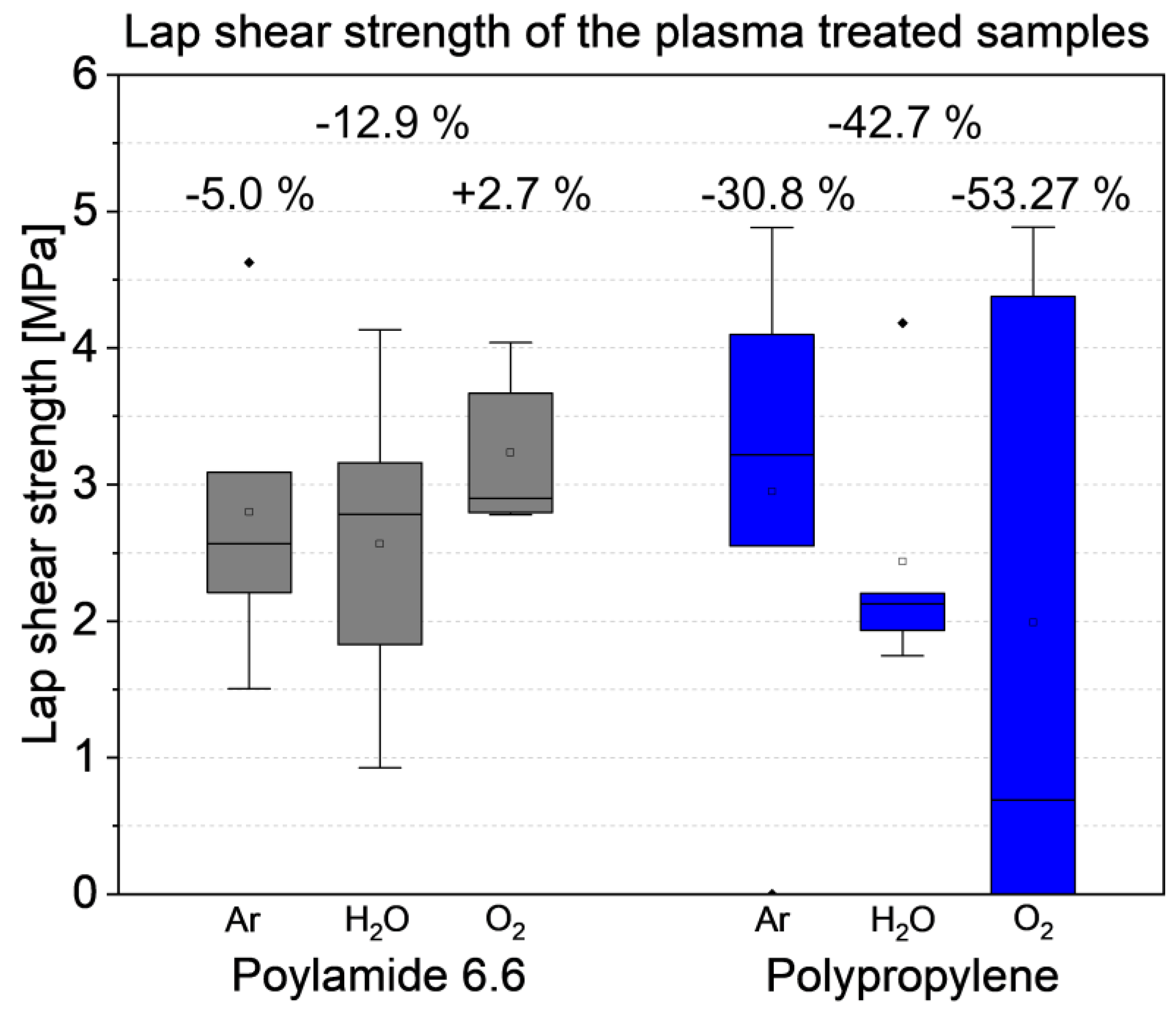
Figure 16.
Macroscopic overview of two overlap joints with O2-Plasma treated polymers for 180 s: (a) polyamide 6.6 hybrid with cold-rolled steel; (b) polypropylene hybrid with sand blasted steel.
Figure 16.
Macroscopic overview of two overlap joints with O2-Plasma treated polymers for 180 s: (a) polyamide 6.6 hybrid with cold-rolled steel; (b) polypropylene hybrid with sand blasted steel.
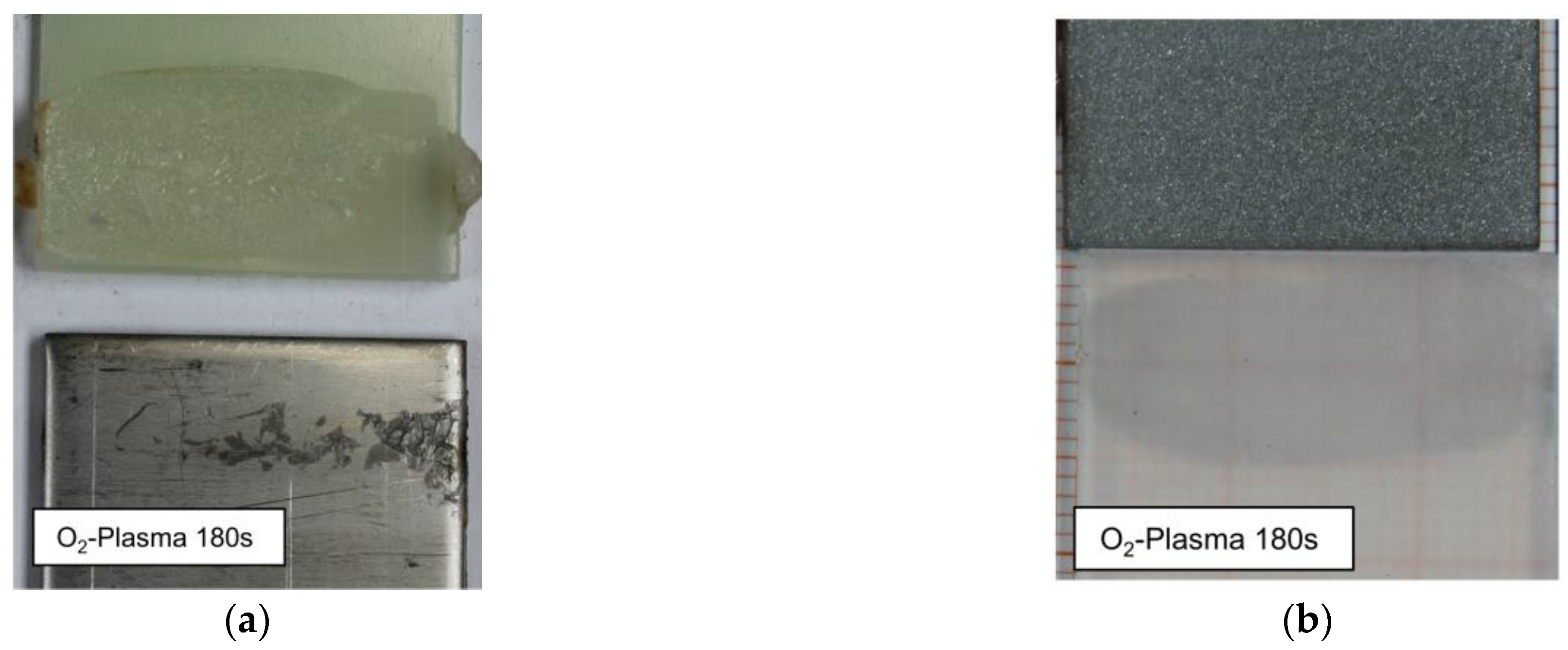
Figure 17.
SEM analysis of the steel samples of the O2-Plasma treated hybrids shown in Figure 14; (a) and (b) shows ETD measurements of the cold rolled AISI304-Polyamide 6.6 sample; (c) and (d) BSE images of the sandblasted AISI304-polypropylene samples.
Figure 17.
SEM analysis of the steel samples of the O2-Plasma treated hybrids shown in Figure 14; (a) and (b) shows ETD measurements of the cold rolled AISI304-Polyamide 6.6 sample; (c) and (d) BSE images of the sandblasted AISI304-polypropylene samples.
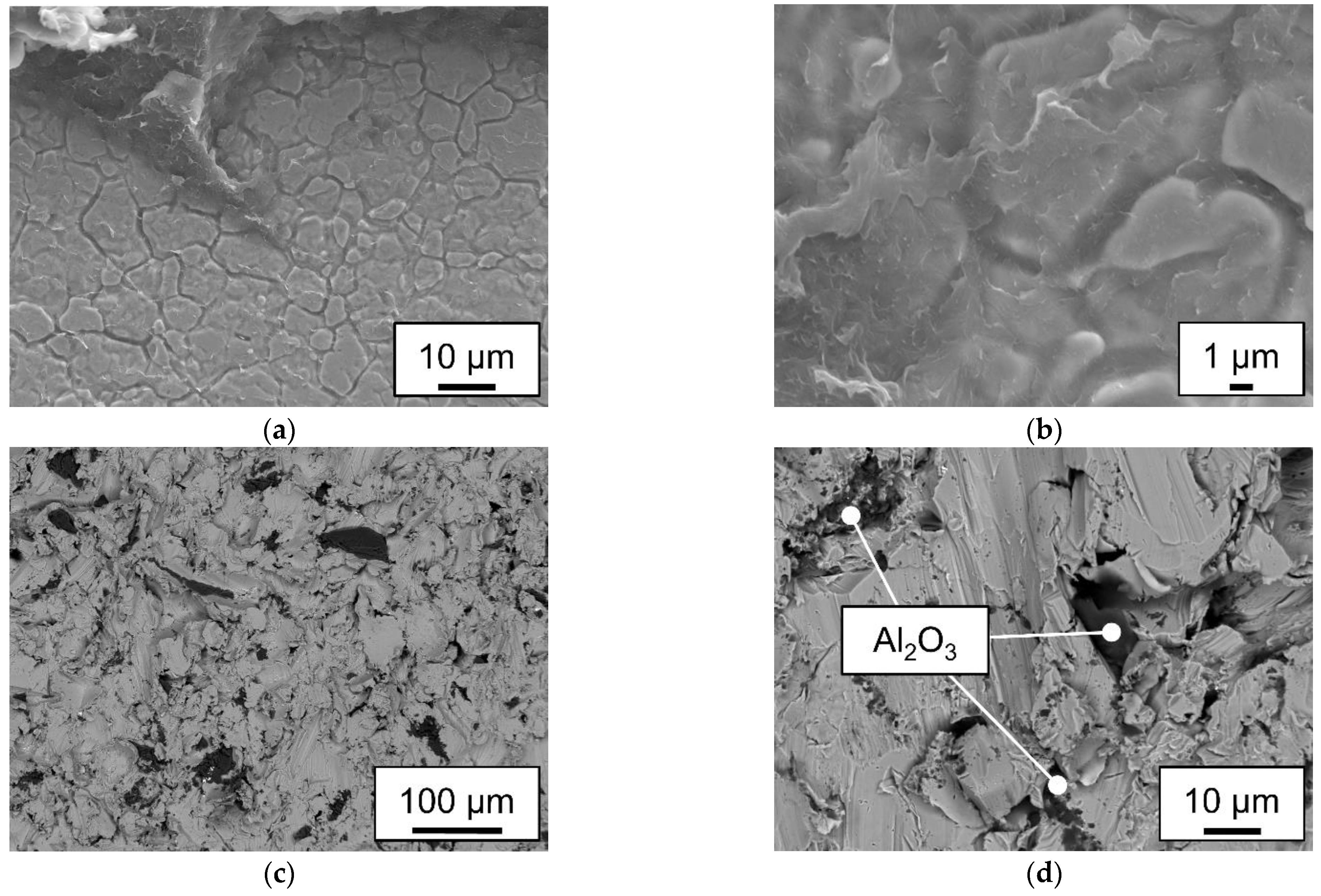
The polyamide 6.6 residue on the steel sample shown on Figure 15 (a) and (b) are slightly different then in the untreated state. The residue seems to be more fractured in comparison. Also, the residue is also prominent on the flatted-out grains on the cold-rolled steel surface. The more brittle behavior of polyamide 6.6 can be the result of the treatment at low-pressure. It is known that the water content of polyamide 6.6 leads to higher ductility [26]. A treatment at low-pressure can reduce the water content especially in the surface area. This is an explanation for the more brittle behavior and the loss of lap shear strength of the Ar and H2O-Plasma treated samples. Figure 15 (c) and (d) show the sand blasted steel of a plasma treated polypropylene hybrid. The steel shows the same fissured surface as the untreated sample, with the same Al2O3 embedding. No residue of polypropylene or any other additional phase could be detected. This leads to the assumption that the polar groups added to the surface of the polypropylene samples did not create a covalent bond with the steel surface. This hypothesis agrees with the findings of Scheick. He postulated that the created polar groups would realign inwards within the melting process and would not increase the strength between plastic and metal [27].
4. Conclusions
The goal of this investigation was to identify the correlation between a low-pressure plasma treatment and the lap shear strength of laser joined metal and plastic hybrids. The focus was on the relation between the surface free energy, the lap shear strength and possible residue on the surface of the metal due to covalent bonds. The achieved results can be summed up as follows:
- I.
- Unpolar plastics like the used polypropylene needs sufficient mechanical adhesion when used within a laser joining process with metals. No plastic residue could be detected on the fractured surface.
- II
- Polyamide 6.6 hybrids can be joined without mechanical adhesion on smooth surfaces. The adhesively fractured samples leave residues on the steel surface. Higher line energies can cause cohesive failure of the plastic sample.
- III.
- Low-pressure plasma treatments with argon, oxygen and water as plasma gases increase the surface free energy significantly. The disperse and polar values calculated by the OWRK-Method were on the same level at 180 s treatment time.
- IV
- The low-pressure plasma treated polyamide 6.6 samples showed slightly varying lap shear strengths. The variation was in the range of the untreated samples. The drying effect of the low-pressure treatment increased the number of cohesively failed samples. This lead also to a more fractured appearance of the residue on the steel sample.
- V.
- The lap shear strength of the plasma treated polypropylene samples decreased significantly, especially within the oxygen plasma. This was attributed to overaging and the creation of Low Molecular Weight Oxidized Materials (LMWOM) on the surface.
These findings are in contrast to Al Sayyad et al [19] which identified a correlation between the surface free energy and the lap shear strength of laser joined metal and plastic hybrids. In this research the low-pressure plasma treatment had no or a negative influence on the lap shear strength. Additionally, the creation of polar groups on the unpolar polypropylene did not lead the formation of covalent bonds between the plastic and the steel surface.
Author Contributions
Conceptualization, C.T.; methodology, C.T.; validation, C.T. and L.W.; formal analysis, C.T.; data curation, C.T.; writing—original draft preparation, C.T.; writing—review and editing, L.W. and P.F.; visualization, C.T.; supervision, W.T. and C.H; project administration, W.T. and C.H.; funding acquisition, W.T. and C.H. All authors have read and agreed to the published version of the manuscript.
Funding
This research was funded by the German Research Foundation (DFG, TI 343/170-1, HO 4776/56-1).
Informed Consent Statement
Not applicable.
Data Availability Statement
Not applicable.
Acknowledgments
Not applicable.
Conflicts of Interest
The authors declare no conflict of interest.
References
- Lambiase, F. Joinability of different thermoplastic polymers with aluminium AA6082 sheets by mechanical clinching. Int J Adv Manuf Technol 2015, 80, 1995–2006. [Google Scholar] [CrossRef]
- Lambiase, F. Mechanical behaviour of polymer–metal hybrid joints produced by clinching using different tools. Materials & Design 2015, 87, 606–618. [Google Scholar] [CrossRef]
- Abibe, A.B.; Amancio-Filho, S.T.; dos Santos, J.F.; Hage, E. Mechanical and failure behaviour of hybrid polymer–metal staked joints. Materials & Design (1980-2015) 2013, 46, 338–347. [Google Scholar] [CrossRef]
- Feraboli, P.; Masini, A. Development of carbon/epoxy structural components for a high performance vehicle. Composites Part B: Engineering 2004, 35, 323–330. [Google Scholar] [CrossRef]
- Sarlin, E.; Heinonen, E.; Vuorinen, J.; Vippola, M.; Lepistö, T. Adhesion properties of novel corrosion resistant hybrid structures. International Journal of Adhesion and Adhesives 2014, 49, 51–57. [Google Scholar] [CrossRef]
- Sadowski, T.; Golewski, P.; Zarzeka-Raczkowska, E. Damage and failure processes of hybrid joints: Adhesive bonded aluminium plates reinforced by rivets. Computational Materials Science 2011, 50, 1256–1262. [Google Scholar] [CrossRef]
- Lugauer, F.P.; Kandler, A.; Meyer, S.P.; Wunderling, C.; Zaeh, M.F. Induction-based joining of titanium with thermoplastics. Prod. Eng. Res. Devel. 2019, 13, 409–424. [Google Scholar] [CrossRef]
- Yeh, R.-Y.; Hsu, R.-Q. Development of ultrasonic direct joining of thermoplastic to laser structured metal. International Journal of Adhesion and Adhesives 2016, 65, 28–32. [Google Scholar] [CrossRef]
- Cenigaonaindia, A.; Liébana, F.; Lamikiz, A.; Echegoyen, Z. Novel Strategies for Laser Joining of Polyamide and AISI 304. Physics Procedia 2012, 39, 92–99. [Google Scholar] [CrossRef]
- Bergmann, J.P.; Stambke, M. Potential of Laser-manufactured Polymer-metal hybrid Joints. Physics Procedia 2012, 39, 84–91. [Google Scholar] [CrossRef]
- Tillmann, W.; Elrefaey, A.; Wojarski, L. Toward process optimization in laser welding of metal to polymer. Prozessoptimierung beim Laserstrahlschweißen von Metall mit Kunststoff. Mat.-wiss. u. Werkstofftech. 2010, 41, 879–883. [Google Scholar] [CrossRef]
- Kawahito, Y.; Tange, A.; Kubota, S.; Katayama, S. Development of direct laser joining for metal and plastic. In International Congress on Applications of Lasers & Electro-Optics. ICALEO® 2006: 25th International Congress on Laser Materials Processing and Laser Microfabrication, Scottsdale, Arizona, USA, October 30–November 2, 2006; Laser Institute of America, 2006; p 604, ISBN 978-0-912035-85-7.
- Chen, Y.J.; Yue, T.M.; Guo, Z.N. A new laser joining technology for direct-bonding of metals and plastics. Materials & Design 2016, 110, 775–781. [Google Scholar] [CrossRef]
- Gao, M.; Liao, W.; Chen, C. Improving the interfacial bonding strength of dissimilar PA66 plastic and 304 stainless steel by oscillating laser beam. Optics & Laser Technology 2021, 138, 106869. [Google Scholar] [CrossRef]
- Schricker, K.; Samfaß, L.; Grätzel, M.; Ecke, G.; Bergmann, J.P. Bonding mechanisms in laser-assisted joining of metal-polymer composites. Journal of Advanced Joining Processes 2020, 1, 100008. [Google Scholar] [CrossRef]
- Katayama, S.; Kawahito, Y. Laser direct joining of metal and plastic. Scripta Materialia 2008, 59, 1247–1250. [Google Scholar] [CrossRef]
- Hirchenhahn, P.; Al Sayyad, A.; Bardon, J.; Felten, A.; Plapper, P.; Houssiau, L. Highlighting Chemical Bonding between Nylon-6.6 and the Native Oxide from an Aluminum Sheet Assembled by Laser Welding. ACS Appl. Polym. Mater. 2020, 2, 2517–2527. [Google Scholar] [CrossRef]
- Hirchenhahn, P.; Al-Sayyad, A.; Bardon, J.; Plapper, P.; Houssiau, L. Binding Mechanisms Between Laser-Welded Polyamide-6.6 and Native Aluminum Oxide. ACS Omega 2021, 6, 33482–33497. [Google Scholar] [CrossRef] [PubMed]
- Al Sayyad, A.; Bardon, J.; Hirchenhahn, P.; Mertz, G.; Haouari, C.; Laurent, H.; Plapper, P. Influence of laser ablation and plasma surface treatment on the joint strength of laser welded aluminum-polyamide assemblies 2017.
- Friedrich, J.; Friedrich, J.G. The plasma chemistry of polymer surfaces: Advanced techniques for surface design; Wiley-VCH-Verl.: Weinheim, 2012; ISBN 978-3-527-64803-0. [Google Scholar]
- Mandolfino, C. Polypropylene surface modification by low pressure plasma to increase adhesive bonding: Effect of process parameters. Surface and Coatings Technology 2019, 366, 331–337. [Google Scholar] [CrossRef]
- Awaja, F.; Gilbert, M.; Kelly, G.; Fox, B.; Pigram, P.J. Adhesion of polymers. Progress in Polymer Science 2009, 34, 948–968. [Google Scholar] [CrossRef]
- Fortunato, A.; Cuccolini, G.; Ascari, A.; Orazi, L.; Campana, G.; Tani, G. Hybrid metal-plastic joining by means of laser. Int J Mater Form 2010, 3, 1131–1134. [Google Scholar] [CrossRef]
- Polášková, K.; Klíma, M.; Jeníková, Z.; Blahová, L.; Zajíčková, L. Effect of Low Molecular Weight Oxidized Materials and Nitrogen Groups on Adhesive Joints of Polypropylene Treated by a Cold Atmospheric Plasma Jet. Polymers (Basel) 2021, 13. [Google Scholar] [CrossRef] [PubMed]
- Du, H.; Komuro, A.; Ono, R. Quantitative and selective study of the effect of O radicals on polypropylene surface treatment. Plasma Sources Sci. Technol. 2023, 32, 75013. [Google Scholar] [CrossRef]
- Baur, E.; Osswald, T.A.; Rudolph, N. Saechtling Kunststoff Taschenbuch; 31. Ausgabe, [komplett überarb., aktualisiert und zum ersten Mal in Farbe]; Hanser: München, 2013; ISBN 978-3-446-43729-6. [Google Scholar]
- Scheik, S. Untersuchungen des Verbundverhaltens von thermisch direkt gefügten Metall-Kunststoffverbindungen unter veränderlichen Umgebungsbedingungen. Dissertation; Rheinisch-Westfälische Technische Hochschule Aachen, Aachen, 2016.
Figure 1.
Schematic figure of (a) direct and (b) indirect laser assisted metal and plastic (LAMP) joining.
Figure 1.
Schematic figure of (a) direct and (b) indirect laser assisted metal and plastic (LAMP) joining.
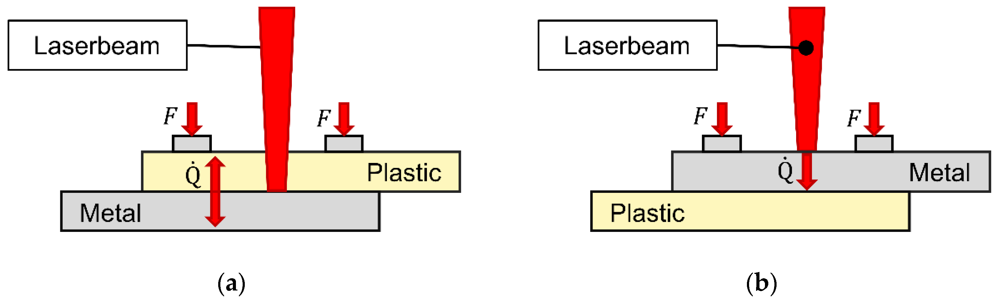
Figure 2.
Chemical structure of (a) polypropylene and (b) polyamide 6.6.
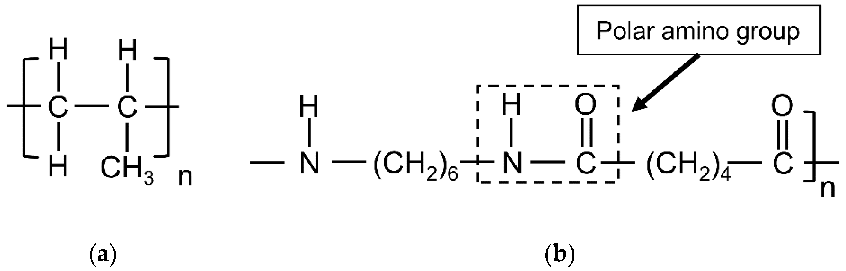
Figure 3.
CAD generated image of the a) laser mount with sample holder and b) sample holder without the cover plate.
Figure 3.
CAD generated image of the a) laser mount with sample holder and b) sample holder without the cover plate.
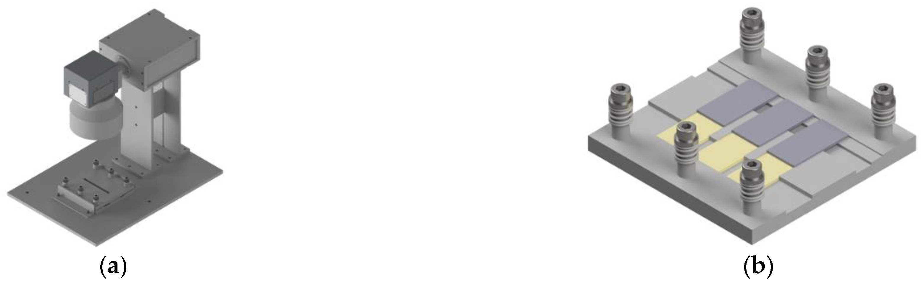
Figure 4.
Lap-shear test setup and sample fixation.
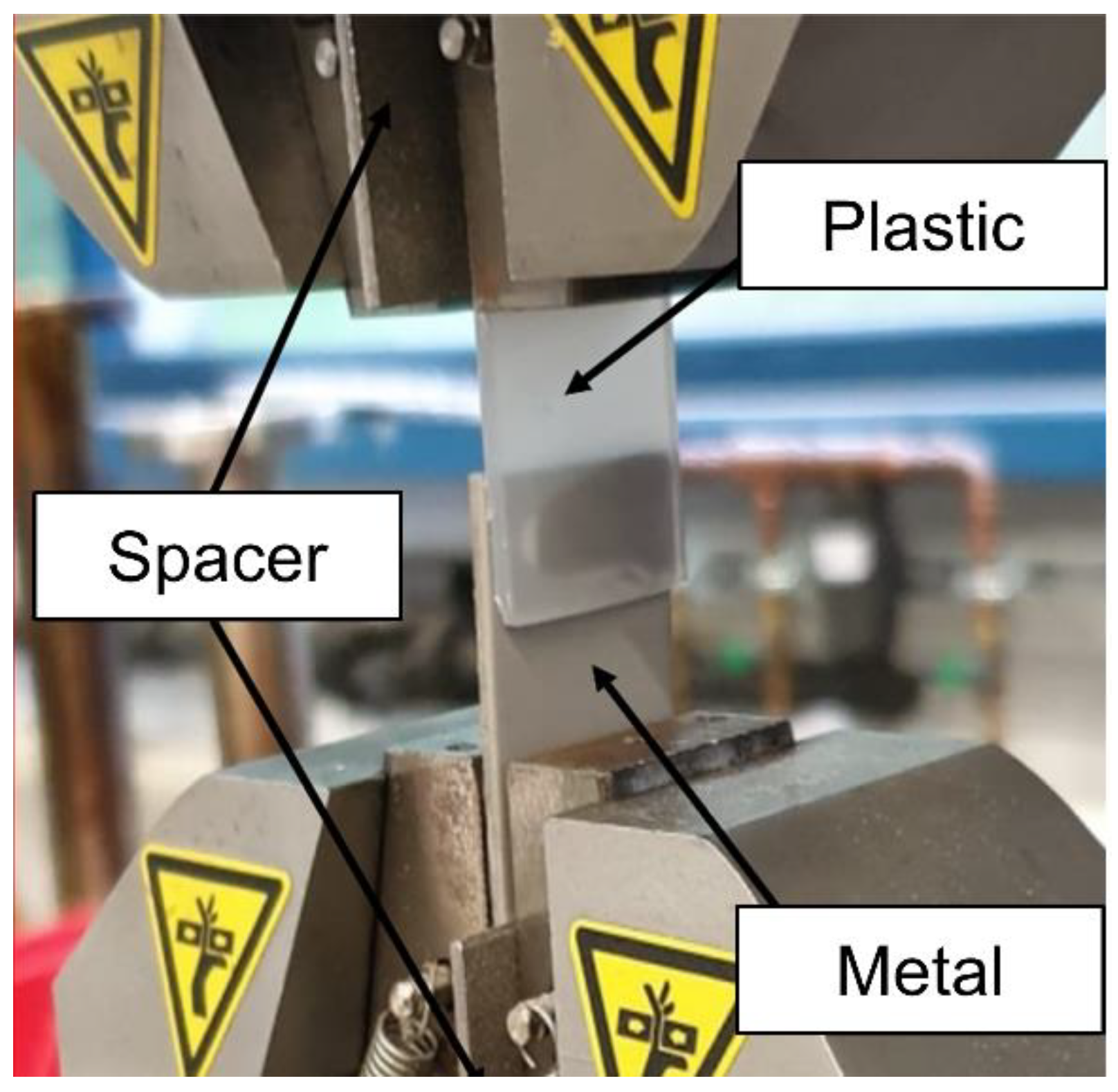
Figure 5.
Lap shear strength of the AISI 304 – Polyamide 6.6 hybrids.
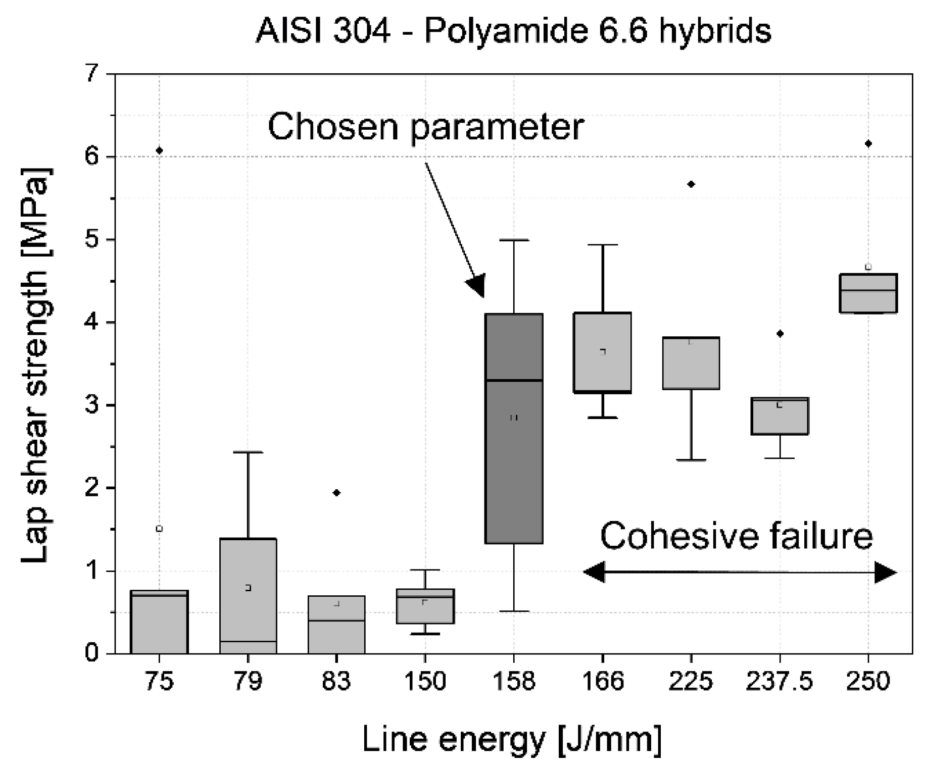
Figure 6.
Cross-section of a AISI 304 – Polyamide 6.6 (PA6.6) hybrid joined with 158 J mm-1 with visible pores and the heat affected zone (HAZ).
Figure 6.
Cross-section of a AISI 304 – Polyamide 6.6 (PA6.6) hybrid joined with 158 J mm-1 with visible pores and the heat affected zone (HAZ).
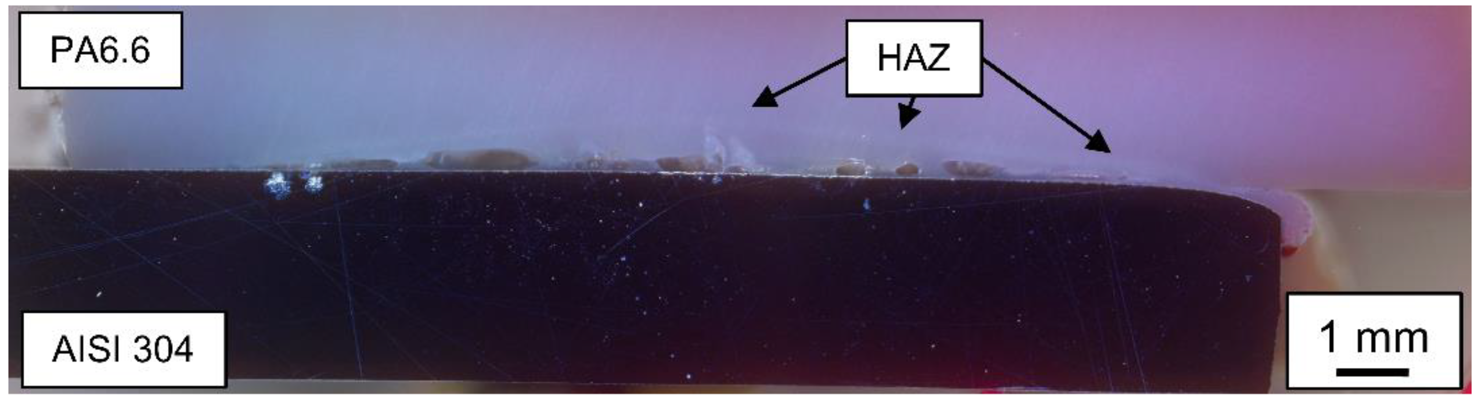
Figure 7.
Failure mechanisms of the AISI 304 – Polyamide 6.6 samples (a) adhesive failure and (b) cohesive failure mode.
Figure 7.
Failure mechanisms of the AISI 304 – Polyamide 6.6 samples (a) adhesive failure and (b) cohesive failure mode.
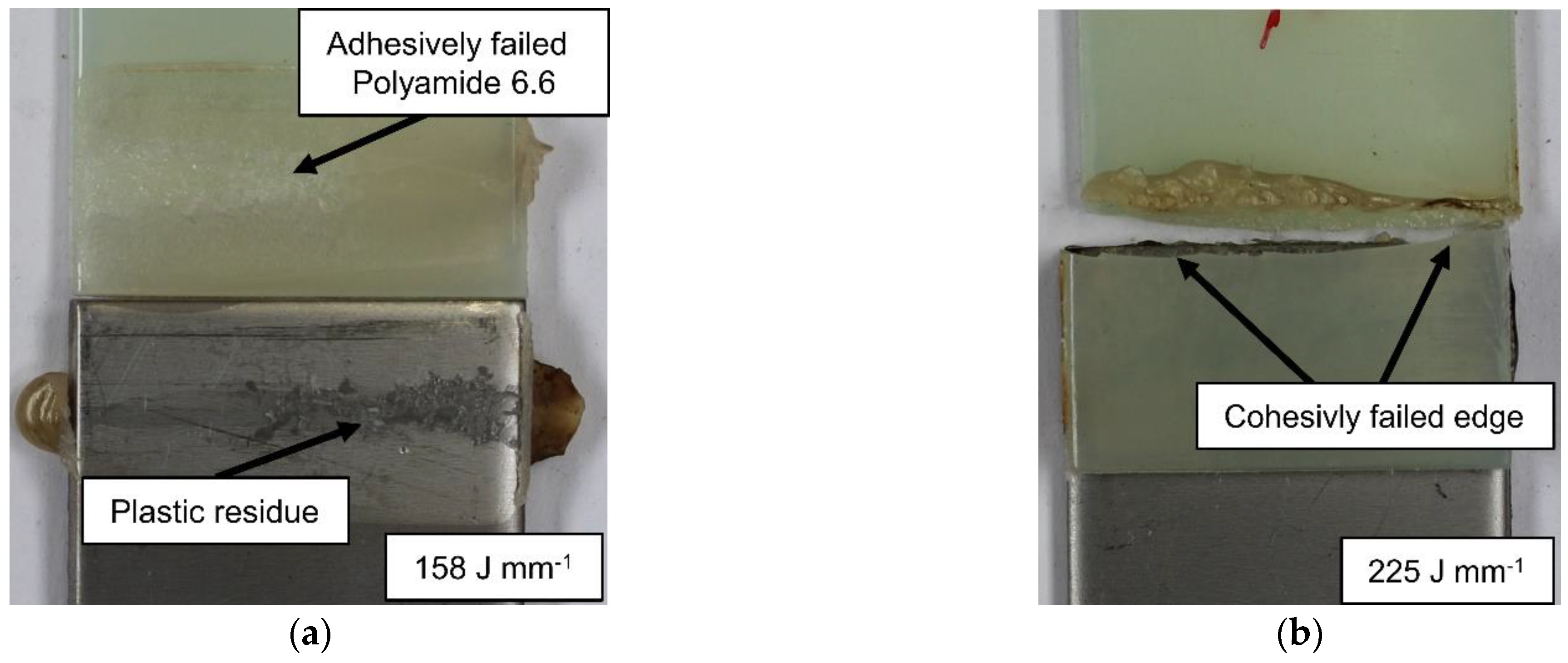
Figure 8.
ETD images of a Polyamide 6.6 – cold rolled AISI 304 lap sheared sample, joined at a line energy of 158 J mm-1: (a) Boundary between macroscopic residue and the steel surface; (b) microscopic view of the steel surface.
Figure 8.
ETD images of a Polyamide 6.6 – cold rolled AISI 304 lap sheared sample, joined at a line energy of 158 J mm-1: (a) Boundary between macroscopic residue and the steel surface; (b) microscopic view of the steel surface.
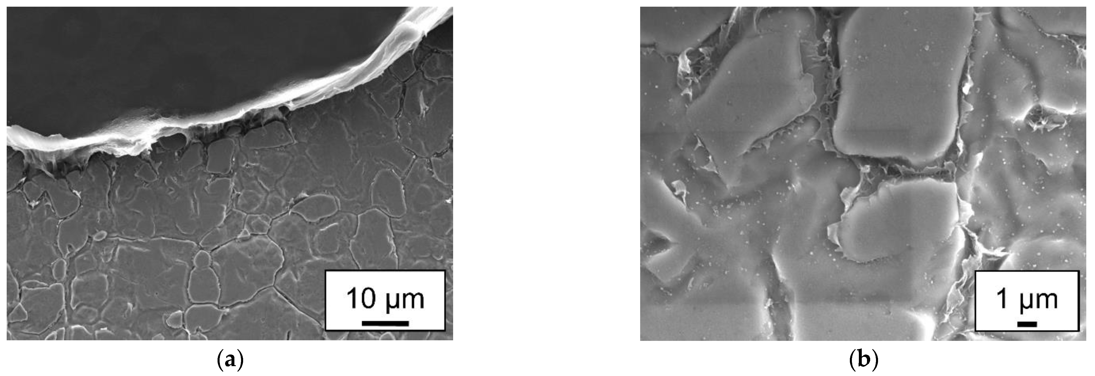
Figure 9.
Lap shear strength of the sandblasted AISI 304 – Polypropylene hybrids.
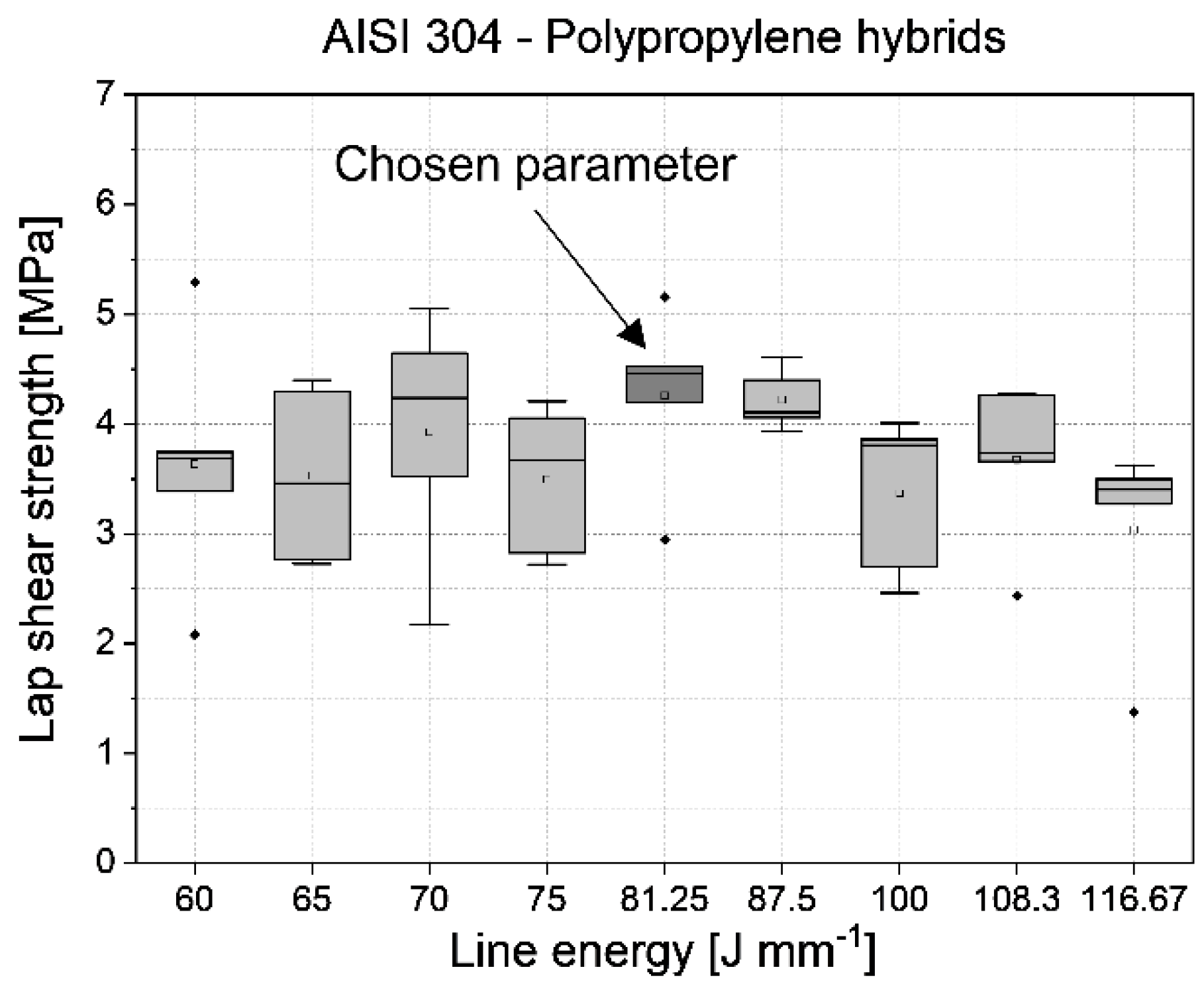
Figure 10.
Cross-section of a AISI 304 – Polypropylene hybrid joined with 81 J mm-1.
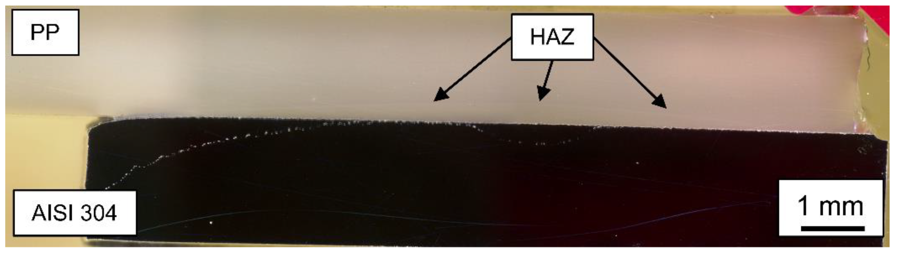
Figure 11.
AISI 304 – Polypropylene samples (a) joined area and (b) adhesive failure.
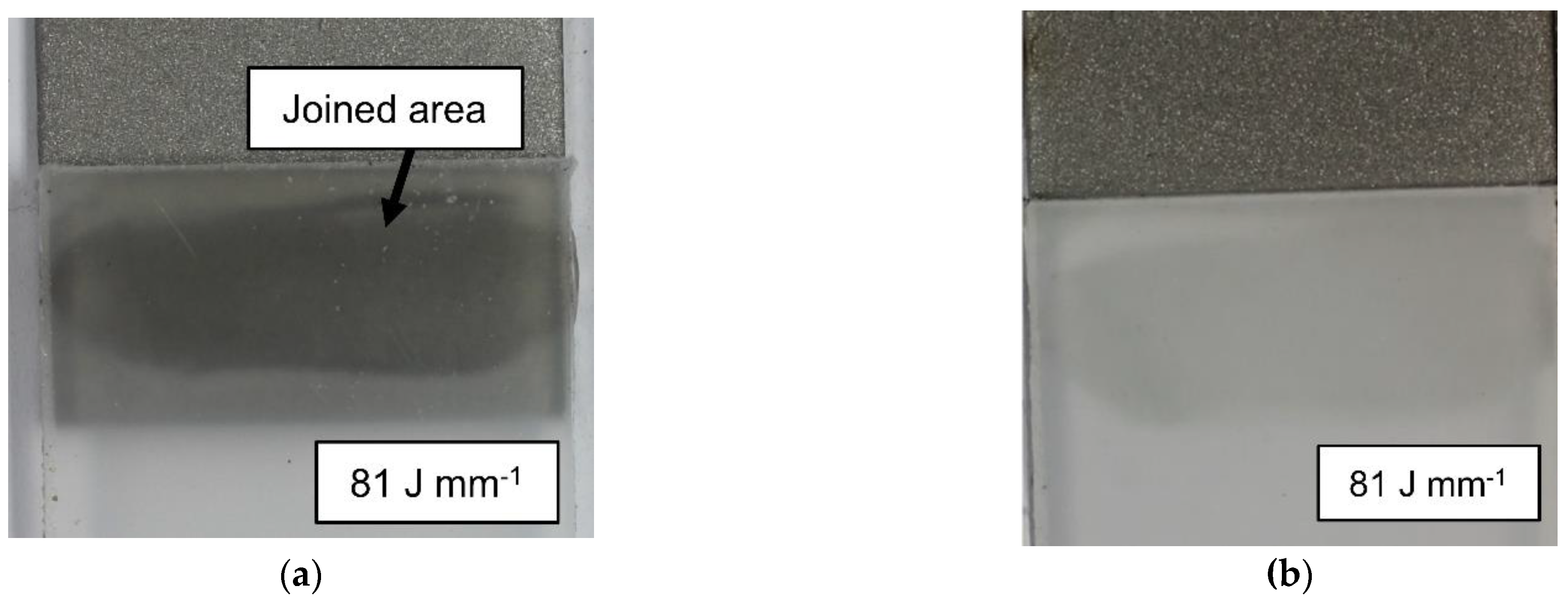
Figure 12.
BSE analysis of the metal sample shown in Figure 10 (a) at a magnification of x200; (b) at a magnification of x1000 with marked areas of Al2O3 particles.
Figure 12.
BSE analysis of the metal sample shown in Figure 10 (a) at a magnification of x200; (b) at a magnification of x1000 with marked areas of Al2O3 particles.
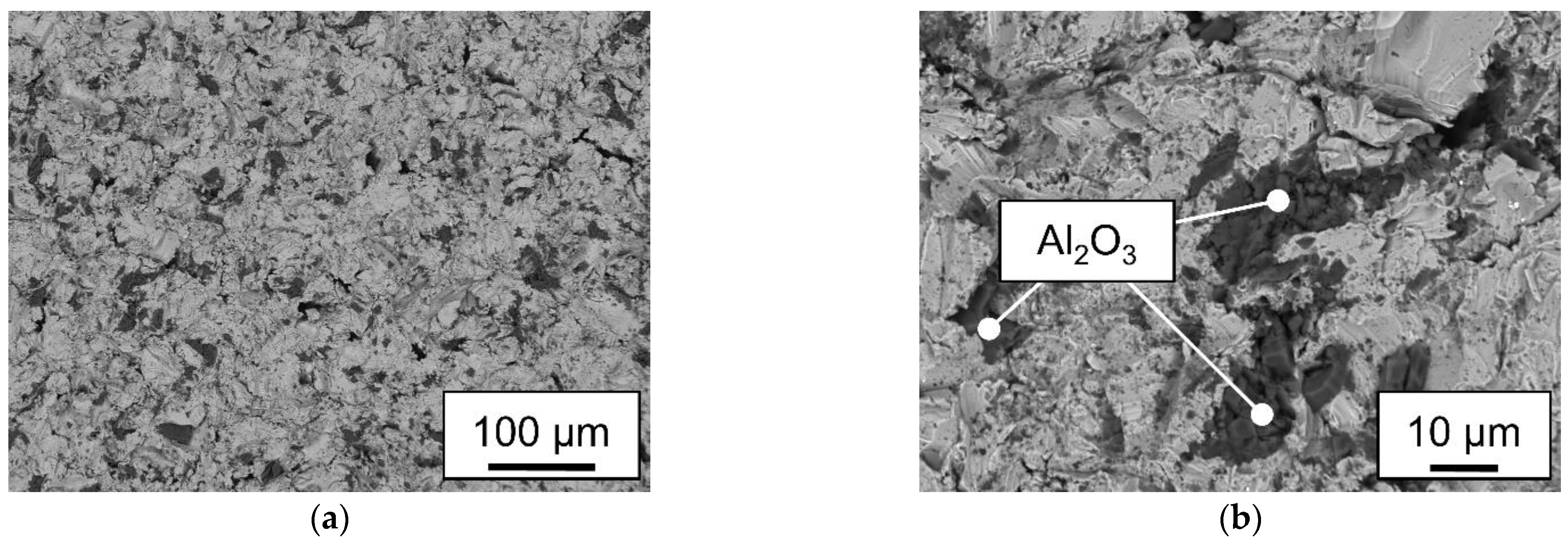
Figure 13.
Image of a water droplet on a polypropylene sample at a magnification of x50 at the following treatment steps: (a) untreated and (b) treated with O2-Plasma for 180s.
Figure 13.
Image of a water droplet on a polypropylene sample at a magnification of x50 at the following treatment steps: (a) untreated and (b) treated with O2-Plasma for 180s.
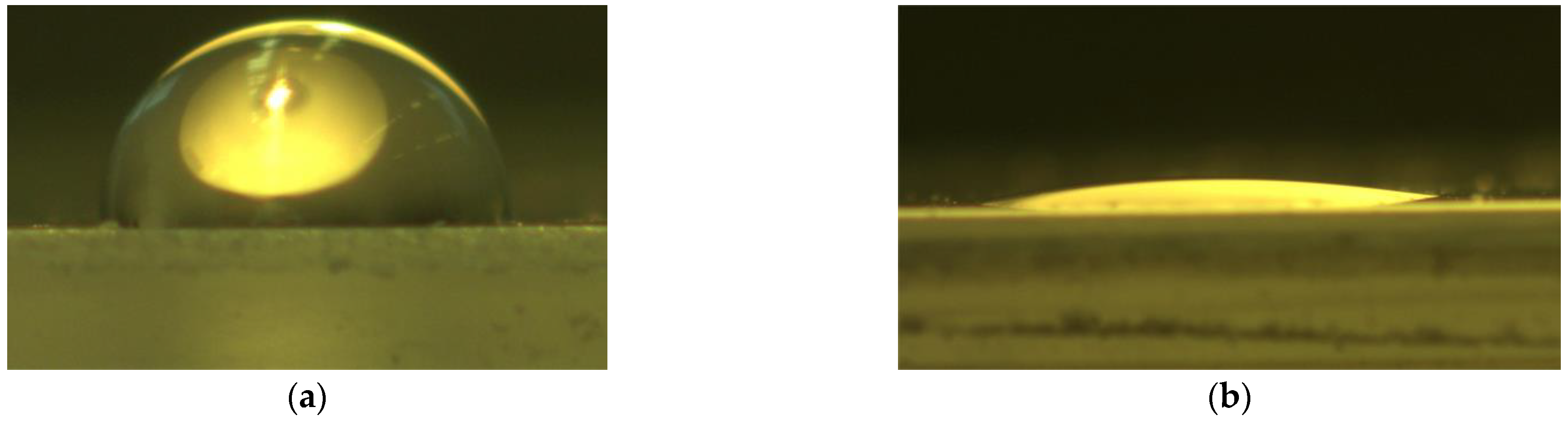
Figure 14.
Surface free energy of the low-pressure plasma and untreated plastic samples.
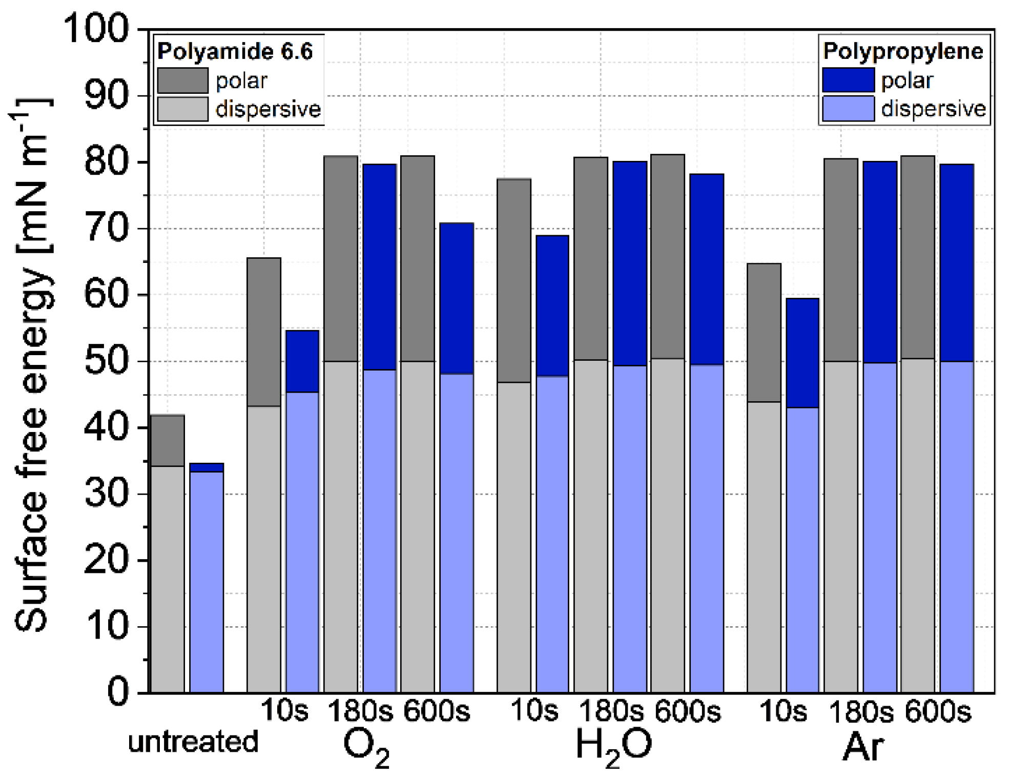

Table 1.
Average surface roughness of the used steel samples.
| Surface | Rz [µm] |
|
|---|---|---|
| X | s | |
| Sand blasted | 14.69 | 1.72 |
| Cold-rolled | 1.44 | 0.35 |
Table 2.
Laser parameters used in this research.
| Plastic | Laser power [W] |
Scanning speed [mm/s] |
Line energy [J/mm] |
||
|---|---|---|---|---|---|
| Polyamide 6.6 | 225, 237.5, 250 | 1, 1.5, 2 | 225 | 238 | 250 |
| 150 | 158 | 167 | |||
| 113 | 119 | 125 | |||
| Polypropylene | 150, 162.5, 175 | 1.5, 2, 2.5 | 100 | 108 | 117 |
| 75 | 81 | 88 | |||
| 60 | 65 | 70 | |||
Table 3.
Surace tensions of the used test liquids.
| Liquid |
[mN m-1] |
[mN m-1] |
[mN m-1] |
|---|---|---|---|
| Water | 72.8 | 51 | 21.8 |
| Diiodomethane | 50.8 | 50.8 | 0 |
Disclaimer/Publisher’s Note: The statements, opinions and data contained in all publications are solely those of the individual author(s) and contributor(s) and not of MDPI and/or the editor(s). MDPI and/or the editor(s) disclaim responsibility for any injury to people or property resulting from any ideas, methods, instructions or products referred to in the content. |
© 2023 by the authors. Licensee MDPI, Basel, Switzerland. This article is an open access article distributed under the terms and conditions of the Creative Commons Attribution (CC BY) license (http://creativecommons.org/licenses/by/4.0/).
Copyright: This open access article is published under a Creative Commons CC BY 4.0 license, which permit the free download, distribution, and reuse, provided that the author and preprint are cited in any reuse.


