Submitted:
01 November 2023
Posted:
02 November 2023
You are already at the latest version
Abstract
In this study, the autofrettage method, which is used to increase the durability of cylindrical parts, was applied to a barrel made of steel material according to the AISI 4340 standard. Assuming that the barrel works continuously under the pressure of 400 MPa, optimum autofrettage was performed. The stresses occurring on the barrel before and after autofretage were calculated. Additionally, analytical equivalent stress values (Von-Mises) formed on the part's wall were compared with numerical analysis results obtained with a commercial finite element program ANSYS®, and their compatibility was examined.
As a result of the calculations and analysis performed, it was observed that autofretage has positive effect on increasing the pressure carrying capacity of the barrel. After autofrettage the cylindrical part, it was determined that the Von-Mises stress values formed in the part wall changed and these stresses took the lowest value at a point (elastic-plastic interface). It has been evaluated that this point gives the optimal autofretage pressure value for a certain operating pressure. After the autofrettage application, it was determined that the Von-Mises Stress value in the barrel wall decreased by 25.27 % and the pressure carrying capacity of the barrel increased without any design or dimensional change. It has been seen that the analytical and numerical analysis results are consistent with each other, and it is expected that this study will guide and contribute to the studies to be conducted on increasing the strength or lightening the weight of the parts.
Keywords:
Plastic Deformation
; Autofrettage
; Residual Stress
; Finite Element Method (FEM)
1. Introduction
Parts operating under repeated loads are exposed to various stresses. Internal pressure exerted on the part creates a mechanical load on the part. The region where the load affects the most is the region where the pressure on the part has the highest value. In this region under the influence of high pressure, high strength is required and this is of great importance in terms of design. To date, many studies have been carried out to increase the strength and fatigue life of parts operating under high and repeated loads.
There are great number of methods used in order to increase the strength of the material and the part. Autofrettage method is one of them As autofrettage is a manufacturing technique that creates partial plastic deformation in thick-walled cylindrical or spherical pressure vessels, so it creates residual stress and increases the pressure bearing capacity of the part [1].
The idea of increasing barrel strength by utilizing residual stresses dates back to the nineteenth century. Until a new method was proposed in 1907, many different applications had been carried out in the arms industry to increase the strength of the barrel. This new method, called autofretage, which means "self-hooping" in French, has begun to be applied as an alternative method to apply pre-tension to gun barrels. The basis of this method is to create a useful compressive residual stress in the part by applying an internal pressure that will cause plastic deformation in some or all of the barrel wall thickness [2].
The equations used for elastic stresses in a thick-walled cylinder subjected to internal pressure were developed by Lame and Clapeyron. However, a full understanding of the stress-related behavior in pressurized thick-walled cylinders was made possible by the maximum shear stress theory introduced by Tresca. The mathematical relations developed for stresses caused by overstress in pressurized thick-walled cylinders made of elastic-plastic material, which define the basic concept of autofretage, were presented by Saint-Venant. While determining the stress area, different assumptions have been proposed regarding the yield criterion, hardening models, and material properties that directly affect the residual stress distribution, and although many studies on these issues have been imparted the literature by many researchers. However, theoretical solutions related to autofretage commonly are based on Lame’s equations using Tresca or Von-Mises yield criteria [3,4,5].
Lame Equations, which were first derived by G. Lame in 1833, are used to calculate the Radial, Tangential and Axial stresses that occur in a thick-walled cylindrical part under the influence of internal and/or external pressure [6].
A cylindrical pipe with inner radius , inner diameter outer radius and wall thickness t is considered as a thick-walled cylinder if it ensures one of the three conditions stated in equation (1) [7].
It has been seen a “thick-walled cylinder” with the inner diameter, and the outer diameter , under the influence of internal and external pressure by Figure 1.
Radial, Tangential and Axial stress values occurring at radius r of a “thick-walled cylinder” as Figure 1. is calculated with the Lame’s equations (2), (3) and (4) given below [8].
Equation (4) gives the stress value in the axial direction caused by the pressure to which the thick-walled cylindrical part is exposed. However, the axial stress occurring in the part operating under pressure varies according to whether the end situation of the cylindrical part are closed or open. The axial stress ( on the wall due to the pressure acting on the part occurs in accordance with one of the situations specified in the equation (5) [9].
The useful residual compressive stresses that occur after the autofrettage application enable the part to which it is applied to withstand a higher pressure. Morover, due to the the useful residual compressive stresses equivalent stress resulting from the internal pressure applied to the cylindrical part does not affect directly the inner surface of the part. The equivalent stress occurs at the elastic-plastic interface. In this way, autofrettage process provides a life-prolonging effect on the part to which it is applied.
The autofrettage process is applied to parts that are widely used in different areas of the industry, such as pressure equipment and associated parts that are exposed to static/repetitive high pressure and temperature loads or corrosive media. Parts and equipment within this scope are generally exposed to mechanical, thermal or a combination of thermomechanical loads. Examples of parts for which autofretage technology is applied are equipment such as thick-walled gun barrels, rocket engines, high-pressure vessels used in the food, chemical, petrochemical industry, pipes and related equipment, submarine hulls, pressurized water reactors in nuclear power plants, automobile combustion chamber cylinders and injection pumps could be given. With the residual stresses that occur after the autofrettage process to be applied, the fatigue life, durability and pressure carrying capacity of these parts can be significantly improved [10,11,12,13].
Autofrettage is also a manufacturing technique with high potential for lightening pressure parts under high stress. If the design is lightened, more than 45 % cost and resource savings can be realized, as well as reductions in wall thickness [14].
An autofrettage pressure () is applied to the inner surface of the part (thick-walled cylinder or sphere) to be autofrettaged, depending on the desired plastic deformation depth. In this way, it is ensured that two regions, an inner plastic region and an outer elastic region, are formed in the part to which autofretage is applied.
The inner plastic region formed starts from the inner radius () and extends to the elastic-plastic interface radius (), which is formed depending on the applied load value. Around this region, an elastic region extends from the elastic-plastic interface radius to the outer radius (). When the applied load is removed, the outer elastic region tries to return to its initial radius value. However, it can’t return to its original state as a result of the permanent deformation occurring in the inner region. Due to this interaction between the plastic region and the elastic region, residual stresses occur in Radial, Tangential and Axial directions on a cylindrical part subjected to pressure.
The elastic-plastic radius value formed in the cylindrical part as a result of the optimum autofrettage process to be applied, taking into account the inner/outer radius of the thick-walled cylindrical part and the service/working pressure is calculated with the equations (6) and (7) for the Tresca and Von Mises equivalent stresses.
The autofrettage pressure ( that must be applied to the part in order to obtain the elastic-plastic radius could be calculated with the equations (8) and (9) for Tresca and Von Mises equivalent stresses [15].
It is the optimum value of the autofrettage pressure calculated by the equations (8) and (9), and a plastic zone at the desired depth can be obtained by increasing the intensity of this pressure. In this way, a more efficient autofrettage operation can be performed.
With the equations (10), (11) and (12), the residual stress values in the Radial, Tangential and Axial directions occurring in the plastic region ( < r < ) after the Autofrettage process could be calculated;
The residual stress values in the Radial, Tangential and Axial directions occurring in the elastic region ( < r < ) could be calculated with the equations (13), (14) and (15).
The total Radial, Tangential and Axial stress values are calculated with the help of the equations (16), (17) and (18) [16].
Today, there are two types of autofrettage that are frequently used in industrial applications and attract the attention of researchers. These are “swage” and “hydraulic” autofrettage methods.
Swage autofrettage is a method in which plastic deformation at the desired depth is obtained by mechanically passing a mandrel larger than the inner diameter of the cylindrical part through the part. Since much higher pressures are produced between the mandrel and the pipe for similar loading values in the swage autofrettage method, very high hydrostatic and radial stresses, which can be up to three times the yield strength, occur in the region close to the interface where the mandrel and the hole are in contact during loading. This feature completely distinguishes Swage autofrettage from other autofrettage methods. It is also energy efficient, economical and safe as a significantly lower pressure is required to drive the mandrel into the part in the mechanical autofrettage process [17].
Accurate analytical modeling of swage autofrettage is difficult, as the contact mechanics problem in Swage autofrettage requires considering both geometry and the effect of material nonlinearity. However, studies on numerical analysis have been carried out by some researchers using the finite element method (FEM) for the modeling of swage autofretage [18,19,20,21,22,23,24].
There are also studies in the literature that contain analytical, numerical and experimental data for the optimization of swage autofretage. A study carried out like this to optimize the wall thickness of a thick-walled cylinder with mechanical autofretage; in a cylinder with fixed inner and outer diameters, a material reduction of 47.8 % was obtained when using only topology without residual stress optimization, 66.5 % by analytical calculation without residual stress optimization and 70.7 % by analytical calculation with residual stress optimization [25,26,27].
Hydraulic autofrettage, on the other hand, is a method based on the use of high hydrostatic pressure applied to the part. While performing the hydraulic autofrettage process, a high pressure is applied, which can reach the levels of 2000 MPa, to achieve the maximum increase in the pressure carrying capacity of the part. Although hydraulic autofrettage is widely accepted in the industrial field, it is a costly and dangerous method because it can be applied to parts with different and complex geometries [28].
There are lots of publications in the literature that include analytical, numerical and experimental analysis focusing on issues such as the strength of the part to which it is applied, crack formation and fatigue life of the part, and optimization related to hydraulic autofretage [29,30,31,32,33,34,35,36].
In addition to these two main autofrettage methods, there are also thermal, rotational and explosive autofrettage methods that attract the attention of researchers more and more.
Thermal autofrettage is an another method that has recently attracted the attention of researchers due to its simplicity and relatively low cost. However, the benefit that can be obtained is limited due to the limitations on the maximum temperature value that can be applied to the part. Various studies on thermal autofrettage applied to thick-walled cylinders are available in the literature [37,38,39,40,41].
In the literature, there are studies on the autofrettage method called rotational autofretage [42]. Explosive autofretage is based on the principle that the pressure created by using an explosive substance causes plastic deformation of the part by making use of a fluid that can easily transmit pressure, such as air or water. Working with explosives requires obtaining various legal permits, and the application process is dangerous and difficult to control. For these reasons, studies with the explosive autofrettage method are limited, but there are various studies in the literature [43].
In the article, analytical calculations and numerical analyses were performed for the model exhibiting Elastic and Strain Hardening Behavior by creating a model belonging to a real part. In order to increase its strength, autofrettage pressure has been applied to the part and thus the pressure value that will cause a certain degree of plastic shape change in the material has been determined. This has been determined at the optimum level by taking into account the pressure value to which the part will be continuously exposed. As a result of the calculations and analyses performed, it has been observed that automatic tension has positive effect on increasing the pressure bearing capacity of the barrel. After the application of autofrettage, it was determined that the Von-Mises stress value on the barrel wall decreased significantly and, similarly, the pressure bearing capacity of the barrel increased without any design or size changes. Morover, it was found that the analytical and numerical analysis results were consistent with each other. This research has been prepared in order to guide, contribute to the studies to be carried out on increasing the strength or lightening the weight of the parts and to show the benefits of the autofrettage method.
2. Material and Method
2.1. Specification of the Material
The material of the barrel, which is the subject of the study, is low-alloyed, high-strength steel in DIN 35NiCrMoV12.5 standard (ASII 4340), and its technical properties are given in Table 1 and Table 2.
The model was created by accepting the 400 MPa service/working pressure, which is the highest pressure in the barrel, and the optimum autofrettage pressure to be applied to the part was determined based on this pressure value.
2.2. Calculation of Equivalent Stress Effects on the Component
Radial, Tangential and Axial stresses occurring on the wall due to the internal pressure acting on the barrel are calculated with the Lame’s equations in the equations (2), (3) and (4). The highest stress value that occurs due to the internal pressure that the barrel is exposed to occurs in the inner radius.
Utilizing from the Radial, Tangential and Axial stresses, Von Mises and Tresca equivalent stress values could be calculated with the equations (20) and (21).
The stress-strain relationship of metalic materials outside the elastic region is mainly defined with two models as shown in Figure 2. In materials that exhibit elastic and Strain hardening behavior and also exhibit stress-strain behavior as in graph (a), the yield strength (tension) corresponds to point [B], the yield strength (ultimate) corresponds to point [C], and the yield strength (compression) corresponds to point [C’]. For a material exhibiting this type of Bilinear Kinematic Hardening behavior, the stress value between point [C] and point [C’] is equal to twice the yield strength (tension). For a thick-walled cylinder with a radius internal, external and , the Elasticity Modulus (E), Tangent Modulus (T), Yield Strength () of the material in question, the pressure that must be applied to the part in order to achieve optimal autofrettage () is obtained with the equation (21). Similarly, in materials exhibiting Elastic-Perfectly Plastic Behavior, the yield strength (b) corresponds to the point [B], the yield strength (compression) corresponds to the point [C’], and the Tangent Modulus (T) value is equal to zero. For a thick-walled cylinder with a radius internal, external and , the Yield Strength (tension) of the material in question the pressure that must be applied to the part in order to perform optimal autofrettage is obtained by the equation () (22).
When defined as (Yield Strength (Compression)) and (Modulus of Elasticity) and T (Tangent Moduls of the material), the optimum autofrettage pressure for a part made of a material exhibiting Elastic and Strain Hardening Behavior is calculated with the equation (21).
Similarly, the optimal autofrettage pressure of a part made of a material exhibiting Elastic-Perfectly Plastic Behavior is calculated with the equation (22) [45].
2.3. The Model and Forming of the Mesh Structure
The barrel with inner radius ) 52.5 mm., outer radius () 96 mm. made of AISI 4340 steel material, the mechanical properties of which are given in Table 2. The analytical calculation and analysis were conducted while considering the barrel’s highest service pressure value. [Figure 3 (b)].
The model in which the analyses were performed was created in the ANSYS ® 2023 R1 Workbench environment as shown in Figure 4.
During the modeling of the part, the assumption was made that the variation in strain along the longitudinal direction of the cylinder would not affect the results. A total of 142074 quadratic elements and 215742 nodes were used in the finite element model.
In the analysis, the pressure was applied from the inner wall of the part in the direction of the outer wall. The applied pressure was defined in 6 steps. In the first step, the working pressure of 400 MPa was applied. In the step 2., the pressure was completely removed and it was observed that there was no deformation in the part. In step 3., the optimum autofrettage pressure calculated by taking into account the operating pressure to which the part is exposed was applied. In the 4th step, the effect of plastic deformation and residual stresses formed by completely removing the pressure was observed. In the step 5, the effects of the beneficial residual stresses obtained through the autofrettage process when the working pressure of 400 MPa was applied to the part were observed. The inner surface on which the pressure is applied and the pressure values are given in Figure 5.
2.4. Autofrettage Application and Determination of Residual Stress
In the study, the part with a service/working pressure of 400 MPa was subjected to the autofrettage process at the optimum level. For this purpose, optimum autofrettage pressure ( was calculated and applied to the part, analytical calculations and analyses were carried out.
After the autofrettage process, residual stress values in the radial, tangential and axial directions in the plastic region ( < r < ) and elastic region ( < r < ) were calculated.
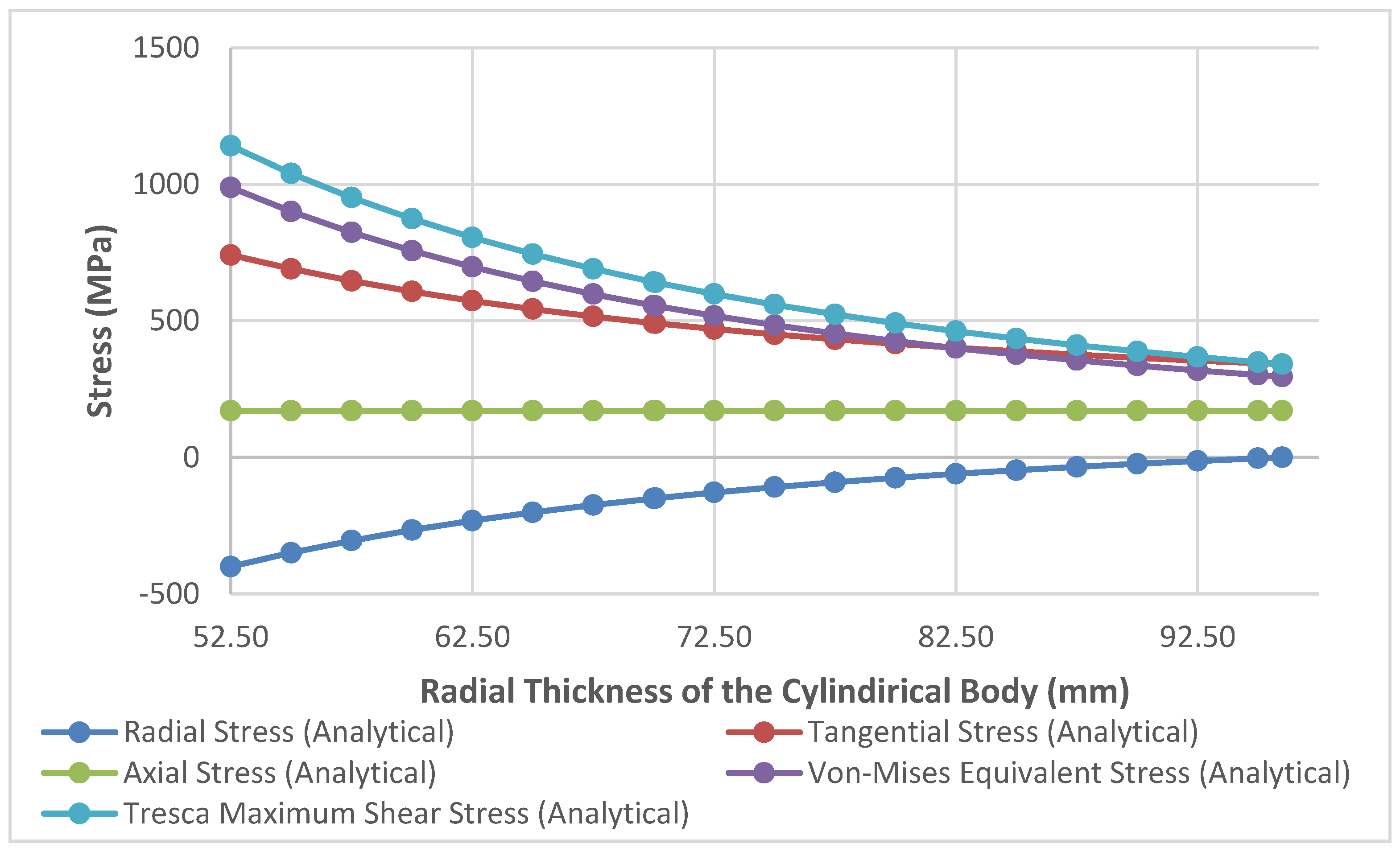
When 400 MPa internal pressure is applied to the part whose dimensions and material specifications are given, the maximum equivalent stress occurs at the inner radius. Stress values here are analytically calculated as 988.43 MPa (Von-Mises) and 1141.34 MPa (Tresca). The applied pressure is observed as a result of analytical calculations that the part in performs its duty safely without damage.
It is seen that the Von-Mises stress analysis results shown in Figure 6. are compatible with the analytical calculation values obtained with Lame’s equations.
As can be seen in the analysis in Figure 7, the part performs safely under repeated 400 MPa pressure, and no plastic deformation occurs on the part wall as soon as the pressure loses its effect.
The autofrettage pressure to be applied to the part in order to perform the autofrettage process at the optimum level for 400 MPa, which is the pressure value it is exposed to, was calculated with the help of the equation (22). When the calculated autofrettage pressure is hydraulically applied to the inner surface of the part, a stress occurs slightly above the material yield strength of 1200 MPa in the inner radius of the part, as seen in Figure 8., and this stress causes a plastic deformation in the inner wall of the part.
When the applied autofrettage pressure is removed, the part outside the plastic deformation area tries to return to its original state and as a result of this, benefical residual stresses occur. (Figure 9 ve Figure 10)
When 400 MPa, which is accepted as service pressure, is applied to the autofrettaged part, the equivalent stress that occurs decreases with the effect of residual stresses, provides the part’s resistance to higher pressure values with its current design and causes an increase in the pressure bearing capacity. Equivalent Von-Mises stresses occurring in the part wall under service pressure are given in Figure 11.
The analytical calculation and analysis results for the Von-Mises Equivalent stress values obtained when the part, after beneficial residual stresses were created by applying the autofrettage process at the optimum level for the working pressure of 400 MPa, are under the effect of 400 MPa working pressure, are shown in Table 3.
Figure 12.
Analytical Results of Stress Distribution in Non-Autofrettaged Barrel under Service Pressure.
Figure 12.
Analytical Results of Stress Distribution in Non-Autofrettaged Barrel under Service Pressure.
Similarly; The total stresses calculated by including the effect of residual stresses after the autofrettage process when the part is under 400 MPa service pressure are shown in Figure 13.
Figure 13.
FEM Results of Stress Distribution in Non-Autofrettaged Barrel under Service Pressure.
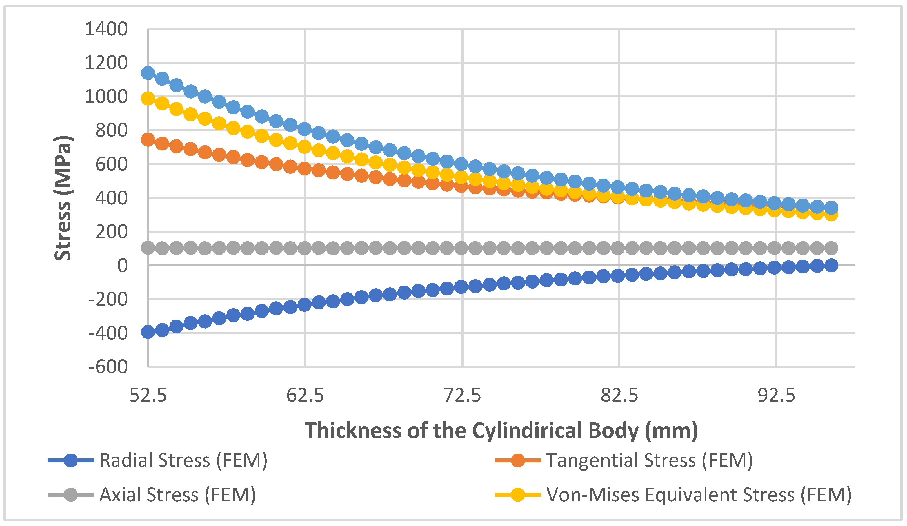
Figure 14.
Analytical Results of Stress Distributions of the Barrel under Autofrettage Pressure.
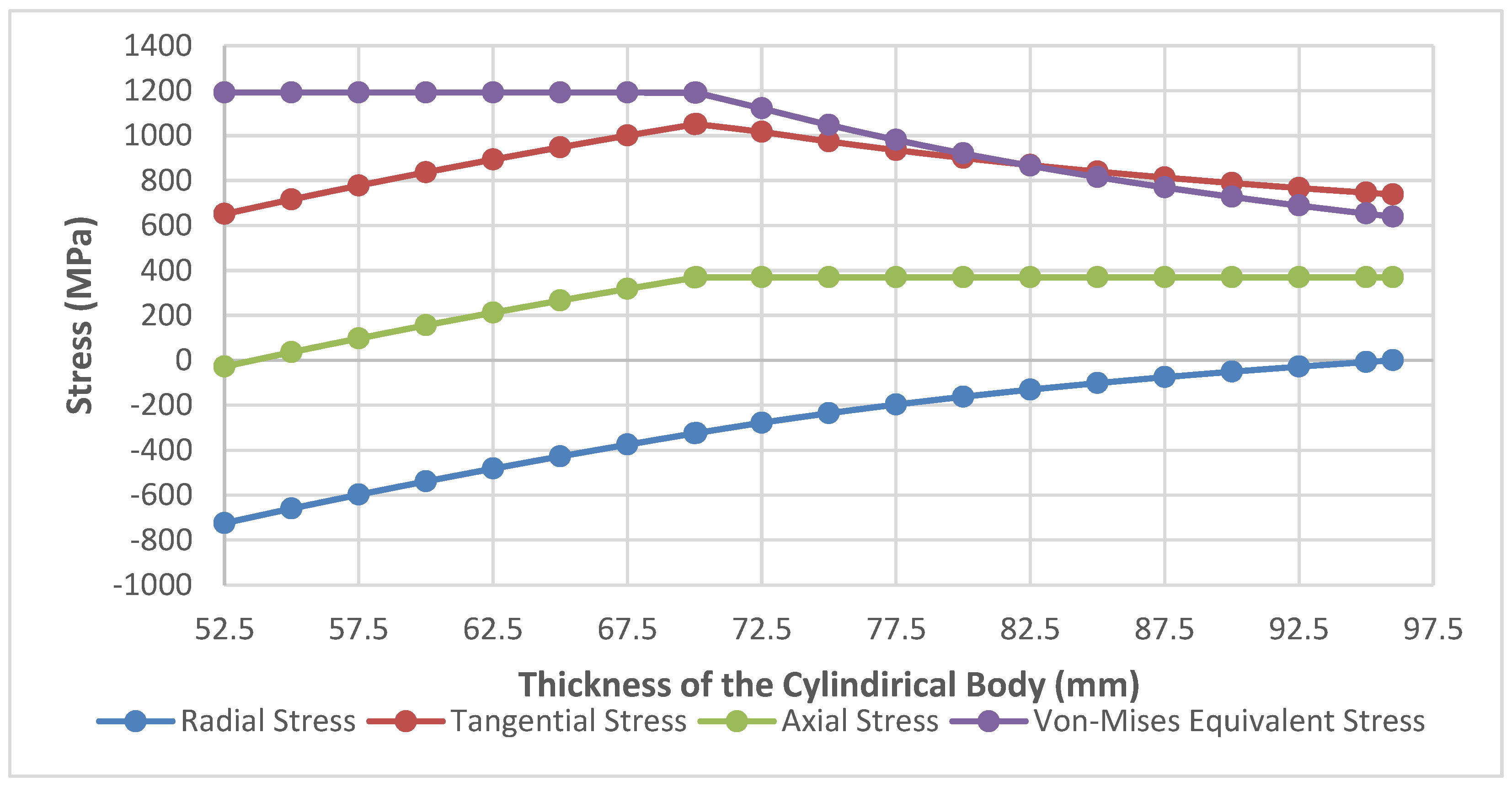
Figure 15.
FEM Results of Stress Distributions of the Barrel under Autofrettage Pressure.
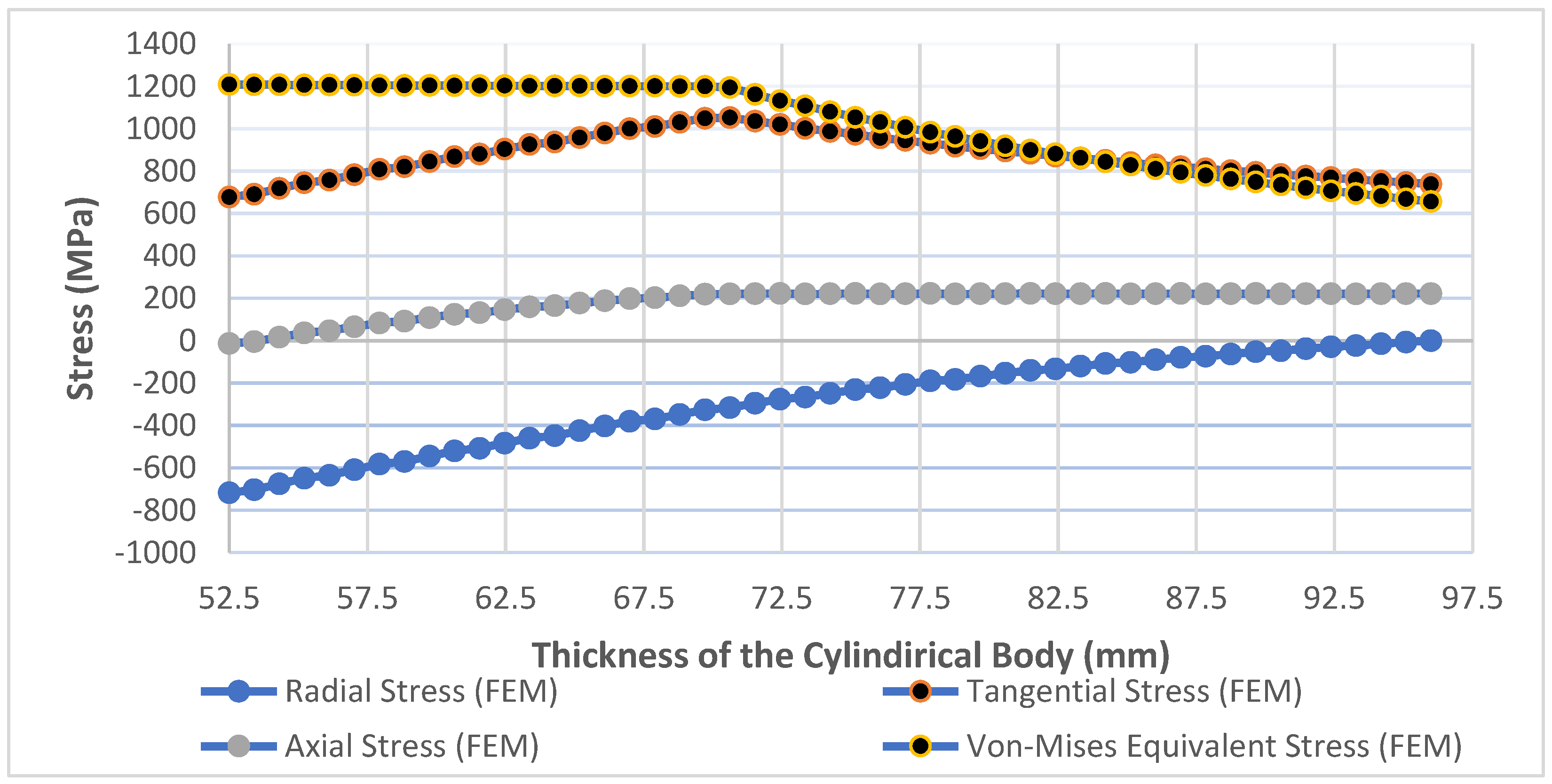
Figure 16.
Residual Stress Variation in the Barrel Wall after Autofrettage Process (Analytical).
Figure 17.
Radial, Tangential and Longitudinal Stresses (Including Residuals) Variation in the Barrel Wall.
Figure 17.
Radial, Tangential and Longitudinal Stresses (Including Residuals) Variation in the Barrel Wall.
Figure 18.
Changing of the Total Stress Along the Radius Before and After the Autofrettage Operation.
Figure 18.
Changing of the Total Stress Along the Radius Before and After the Autofrettage Operation.
3. Conclusion
In this research study, the autofrettage method, which is used to increase the strength and fatigue life of thick-walled cylindrical parts operating under high pressure and repeated load, was applied to a steel barrel piece made of AISI 4340 standard material. For 400 MPa, which is the maximum internal pressure the barrel is exposed to, the stresses occurring in the wall of the cylindrical part were calculated analytically depending on the radius value. Analytical calculations were carried out with the assumption that the material exhibits Elastic and Strain Hardening behavior.
Within the scope of the study, the optimum autofrettage pressure was calculated for the 400 MPa service pressure acting on the component, and a finite element analysis was conducted by applying it to the inner surface of the part. As a result of the applied autofrettage pressure, it has been observed that a plastic deformation occurs on the inner surface of the part, and permanent deformation occurs due to residual stresses that start from the outer radius of the part and extend to the elastic-plastic radius. After autofrettage, it has been observed through analytical calculations and analyses that these beneficial ’Compressive Residual Stresses’ generated a pressure from the outer surface of the part to the inner part, increasing the part’s pressure-bearing capacity.
It has been determined that the stress values on the non-autofrettaged body at the working pressure of 400 MPa are 988.43 MPa (Von-Mises) and 1141.34 MPa (Tresca), and these stresses occur directly on the inner wall of the part.
In addition, it has been determined that, as a result of the residual stresses formed after the application of the optimum autofrettage on the component, the maximum stress value in the part decreased to 735.14 MPa (Von-Mises). Furthermore, it has been assessed that due to these maximum stress values occurring at the elastic-plastic radius rather than on the inner surface, the inner surface of the part is subjected to a lower stress.
As a result of the benefit provided by autofrettage; For the determined working pressure (400 MPa), it was observed that the stress value on the part wall decreased by 25.27 % (Von-Mises). It has been evaluated that the reduction of the equivalent stress value acting on the component’s surface and the fact that stress occurs at the interface instead of the inner surface provide a benefit that increases the fatigue life, especially in parts subjected to repeated loads.
Morover, it has been determined that with the current dimensions of the barrel, it provides an increase in the pressure carrying capacity of the barrel due to the optimum autofrettage process.
It has been revealed in this research that the analytical and numerical analysis results are consistent with each other, and it is considered that this study will guide and contribute to the studies to be conducted on increasing the strength or lightening the weight of the parts.
NOMENCLATURE
| P | Pressure |
| r | Radius |
| d | Diameter |
| t | Wall thickness of the cylinder |
| σ | Normal stress |
| υ | Poisson’s Ratio |
| T | Tangent Modulus |
| E | Elasticity Modulus |
| k | Outer radius/Inner radius ratio |
| n | Operating pressure/Yield stress ratio |
Subscripts
| i | Inner |
| o | Outer |
| a | Autofrettage |
| opt | Optimum |
| ser | Operating |
| VM | Von Mises |
| TR | Tresca |
| y | Yield |
| r | Radial |
| Ө | Tangential (Hoop) |
| l | Longitudinal (Axial) |
| R | Residual |
| Σ | Total |
Superscripts
| P | Plastic |
| E | Elastic |
References
- Shufen R., Dixit U. S. A Review of Theoretical and Experimental Research on Various Autofrettage Processes. Journal of Pressure Vessel Technology, ASME. (2018).
- Perl M., Arone R. An Axisymmetric Stress Release Method for Measuring the Autofrettage Level in Thick-Walled Cylinders—Part I: Basic Concept and Numerical Simulation. Journal of Pressure Vessel Technology, ASME. (1994); 116:384-388.
- Zare H.R., Darijani H. A Novel Autofrettage Method for Strengthening and Design of Thick-Walled Cylinders. Materials & Design. (2016); 105:366-374.
- David P. K. A Short History of High Pressure Technology From Bridgman to Division 3. Journal of Pressure Vessel Technology, ASME. (2000);122:229-233.
- Perl M., Perry J. An Experimental-Numerical Determination of the Three-Dimensional Autofrettage Residual Stress Field Incorporating Bauschinger Effects. Journal of Pressure Vessel Technology, ASME. (2006);128:173-178.
- Kassir M. Applied Elasticity and Plasticity. CRC Press Taylor & Francis Group. (2018);303.
- Vullo V. Circular Cylinders and Pressure Vessels Vincenzo Vullo Stress Analysis and Design. Springer International Publishing, Springer Series in Solid and Structural Mechanics. (2014);3:73.
- Subramanian BY R. Strength of Materials (2nd Edition). Oxford University Press. (2010);737.
- Chakrabarty J. Theory of Plasticity. Elsevier Butterworth-Heinemann. (2006);333.
- Ma Q., Levy C., Perl M. A Study of the Combined Effects of Erosions, Cracks and Partial Autofrettageon the Stress Intensity Factors of a Thick Walled Pressurized Cylinder. Journal of Pressure Vessel Technology, ASME. (2013);135:041403:1:8.
- Kamal S. M. Analysis of Residual Stress in the Rotational Autofrettage of Thick-Walled Disks. Journal of Pressure Vessel Technology, ASME. (2018).
- Abdelsalam O. R., Sedaghati R. Design Optimization of Compound Cylinders Subjected to Autofrettage and Shrink-Fitting Processes. Journal of Pressure Vessel Technology, ASME. (2013);135:021209:1-11.
- Adibi-Asl R., Livieri P. Analytical Approach in Autofrettaged Spherical Pressure Vessels Considering the Bauschinger Effect. Journal of Pressure Vessel Technology, ASME. (2007);129:411-419.
- Brünnet H., Bähre D. Full Exploitation of Lightweight Design Potentials by Generating Pronounced Compressive Residual Stress Fields with Hydraulic Autofrettage. Advanced Materials Research. (2014);907:17-27.
- Ayob A., Elbasheer M. K. Optimum Autofrettage Pressure In Thick Cylinders. Jurnal Mekanikal. (2007);24:1-14.
- H. Yildirim. Analytical and Numerical Analysis of Swage Autofrettage Process Applied to Thick Walled Cylinders”, M.Sc. Thesis, Yıldırım Beyazıt University Graduate School of Natural and Applied Sciences. (2015);42.
- Hu Z., Parker A. P. Swage Autofrettage Analysis – Current Status and Future Prospects. International Journal of Pressure Vessels and Piping. (2019);233–241.
- Malik A. M., Khan M., Rashid B., Khushnood S. Analysis of Swage Autofrettage in Metal Tube. Conference Paper. International Conference on Nuclear Engineering. (2006).
- Hu Z. Design of Two-Pass Swage Autofrettage Processes of Thick-Walled Cylinders by Computer Modeling. Journal of Mechanical Engineering Science. (2018).
- Till E.T., Rammerstorfer F.G. Nonlinear Finite Element Analysis of an Autofrettage Process. Computers & Structures. (1983);17:54:857-864.
- Chen P.C.T. Finite Element Analysis of the Swage Autofrettage Process. Technical Report. US Army Armament Research, Development and Engineering Center. (1988).
- Iremonger M.J., Kalsi G.S. A Numerical Study of Swage Autofrettage. Journal of Pressure Vessel Technology. (2003);125:347.
- Barbachano H, J. M. Alegre, Cuesta I. I. Numerical Simulation of the Swage Tube Forming (STF) in Cylinders. International Journal of Materials Engineering and Technology. (2012).
- Dewangan M. K., Panigrahi S.K. Residual Stress Analysis of Swage Autofrettaged Gun Barrel Via Finite Element Method. Journal of Mechanical Science and Technology. (2015).
- Çelik V., Güngör O., Yıldırım H. Optimization of Mechanical (Swage) Autofrettage Process. Journal of the Faculty of Engineering and Architecture of Gazi University. (2018);34:2:855-863.
- Güngör O, Çelik V. Numerical Evaluation of an Autofrettaged Thick-Walled Cylinder Under Dynamically Applied Axially Non-Uniform Internal Service Pressure Distribution. Defence Technology. (2018).
- Güngör O. An Approach for Optimization of the Wall Thickness (Weight) of a Thick-Walled Cylinder Under Axially Non-Uniform Internal Service Pressure Distribution. Defence Technology. (2017).
- Afzaal Malik M., Khushnood S., Rashid B., Khan M. Hydraulic Autofrettage Technology: A Review. Proceedings of the 16 th International Conference on Nuclear Engineering. (2008).
- Dongxia L., Li L., Xinglei B. Analysis of Optimal Autofrettage Pressure on CFRP Pressure Vessels Using ANSYS. Applied Mechanics and Materials. (2013);184-188.
- Ashikhmin V. N., Gitman M. B., Trusov P. V. Optimal Design of Hydrolic Cylinders Subjected to Autofrettage. Strength of Materials. (1998);30:6.
- Ma X. Research on the Best Autofrettage Pressure of Ultra-High Pressure Valve Body. Key Engineering Materials. (2015);667:524-529.
- Perl M., Saley T. Swage and Hydraulic Autofrettage Impact on Fracture Endurance and Fatigue Life of an Internally Cracked Smooth Gun Barrel Part I- The Effect of Overstraining. Elsevier, Engineering Fracture Mechanics. (2017).
- Perl M., Saley T. Swage and Hydraulic Autofrettage Impact on Fracture Endurance and Fatigue Life of an Internally Cracked Smooth Gun Barrel Part II- The Combined Effect of Pressure and Overstraining. Elsevier, Engineering Fracture Mechanics. (2017).
- Moo Han S., Cheol Hwang B., Yoon Kim H., Kim C. Analysis of the Autofrettage Effect in Improving the Fatigue Resistance of Automotive CNG Storage Vessels. International Journal of Precision Engineering and Manufacturing. (2009);10:15-21.
- Alegre J.M., Bravo P., Preciado M. Fatigue Behaviour of An Autofrettaged High-Pressure Vessel for the Food Industry. Elsevier, Engineering Failure Analysis. (2006).
- Çandar H., Filiz İ. H. Experimental Study on Residual Stresses in Autofrettaged Thick-Walled High Pressure Cylinders. High Pressure Research. (2017).
- Mustafa Kamal S. A Theoritical and Experimental Study of Thermal Autofrettage Process. PhD. Thesis, Department of Mechanical Engineering, Indian Enstitute of Technology. (2016).
- Berman I., Pai D. H. Elevated Temperature Autofrettage, Journal of Engineering for Power, ASME. (1967).
- Mustafa Kamal S. Dixit U.S. Feasibility Study of Thermal Autofrettage of Thick-Walled Cylinders. Journal of Pressure Vessel Technology, ASME. (2015);137.
- Shufen R., Dixit U.S. An Analysis of Thermal Autofrettage Process with Heat Treatment. International Journal of Mechanical Sciences. (2018).
- Mustafa Kamal S., Borsaikia A. C., Dixit U.S. Experimental Assessment of Residual Stresses Induced by the Thermal Autofrettage of Thick-Walled Cylinders. J Strain Analysis. (2015).
- Mustafa Kamal S. Estimation of Optimum Rotational Speed for Rotational Autofrettage of Disks Incorporating Bauschinger Effect. Mechanics Based Design of Structures and Machines. (2015).
- Jimmy D. Mote, Larry K. W. Ching, Robert E. Knight, Richard J. Fay’, and Michael A. Kaplan. Explosive Autofrettage of Cannon Barrels. Technical Report. (1971).
- Handbook of Comparative World Steel Standards. ASTM DS67A. (2002);35.
- Çandar H., Filiz İ.H. Optimum Autofrettage Pressure for a High Pressure Cylinder of a Waterjet Intensifier Pump. Universal Journal of Engineering Science. (2017).
- Boresi A.P., Schmidt R.J. Advanced Mechanics of Materials. (2002);108.
Figure 1.
Schematic Representation of Cylindrical Structure Under Pressure.
Figure 2.
(a) Elastic and Strain Hardening Behavior and (b) Elastic-Perfectly Plastic Behavior of the Materials [45].
Figure 2.
(a) Elastic and Strain Hardening Behavior and (b) Elastic-Perfectly Plastic Behavior of the Materials [45].
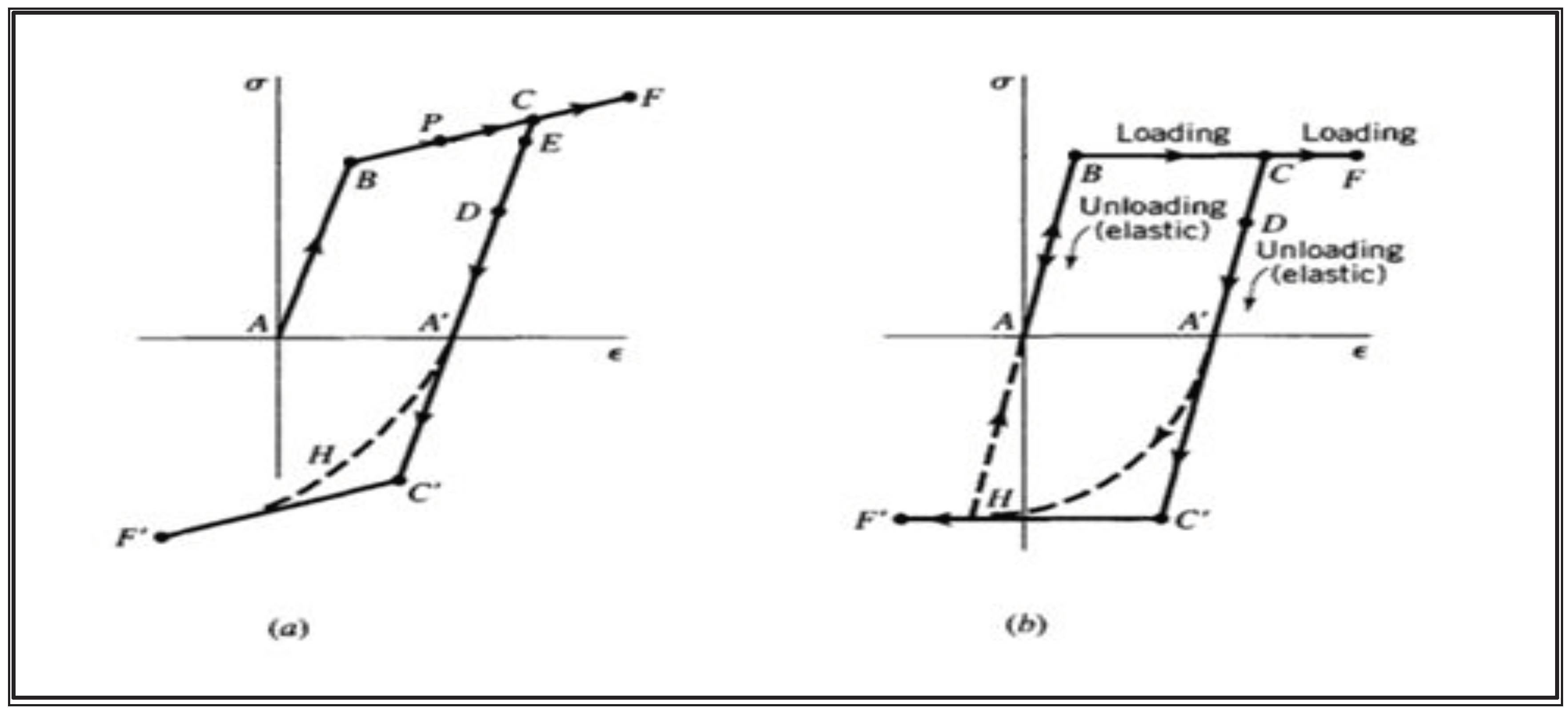
Figure 3.
(a) Solid Model of the Barrel and (b) Cross-Section of the Body.
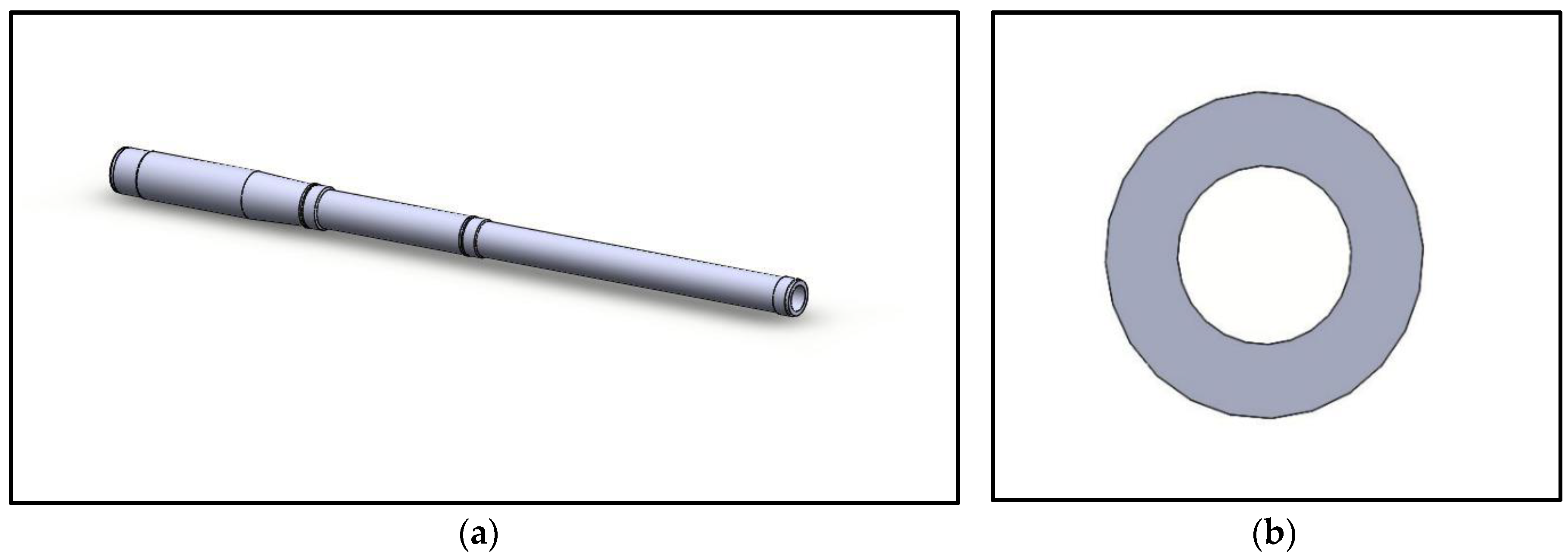
Figure 4.
FEM Model of the Body.
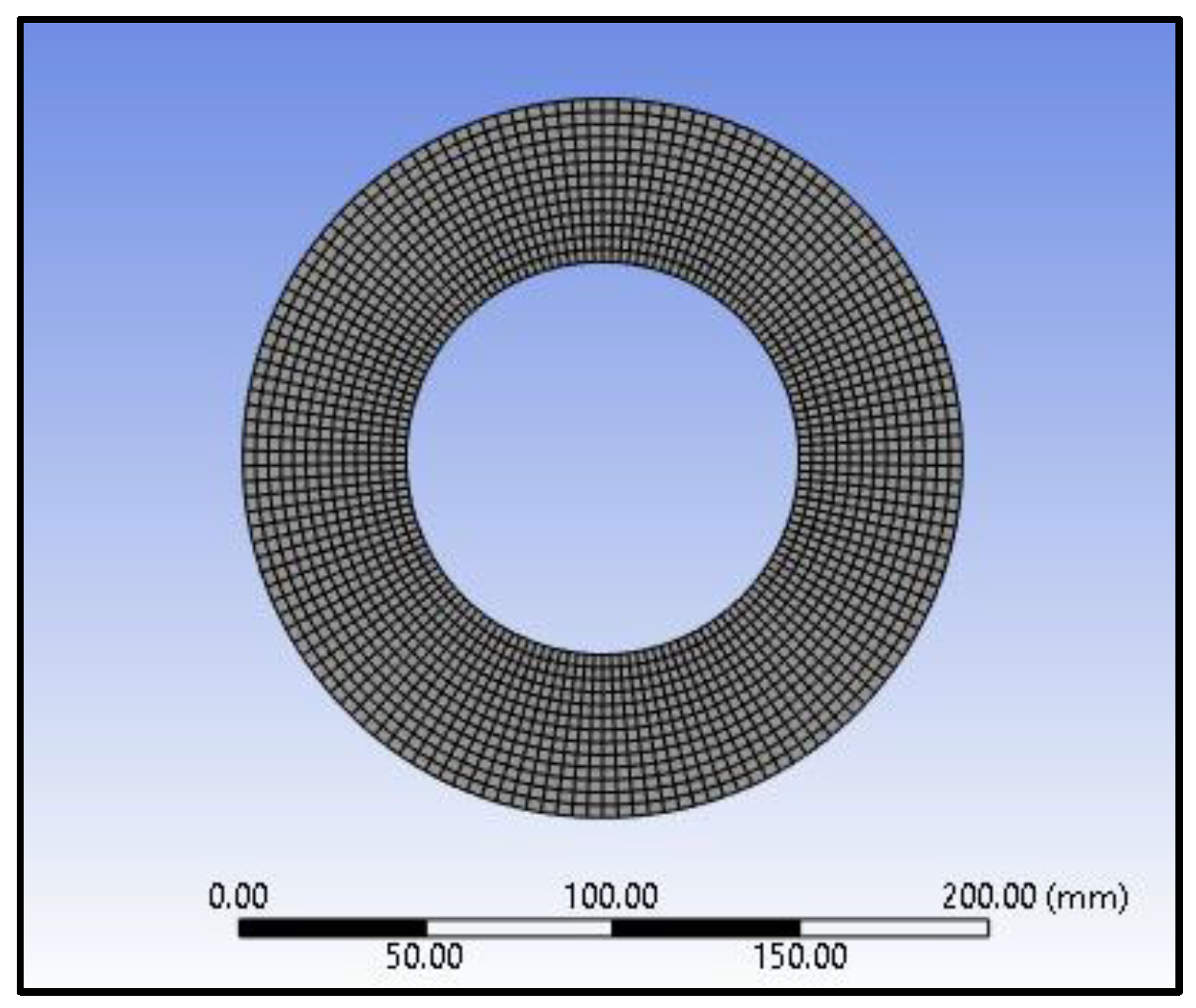
Figure 5.
Pressure Application Steps on the FEM model of the Body.
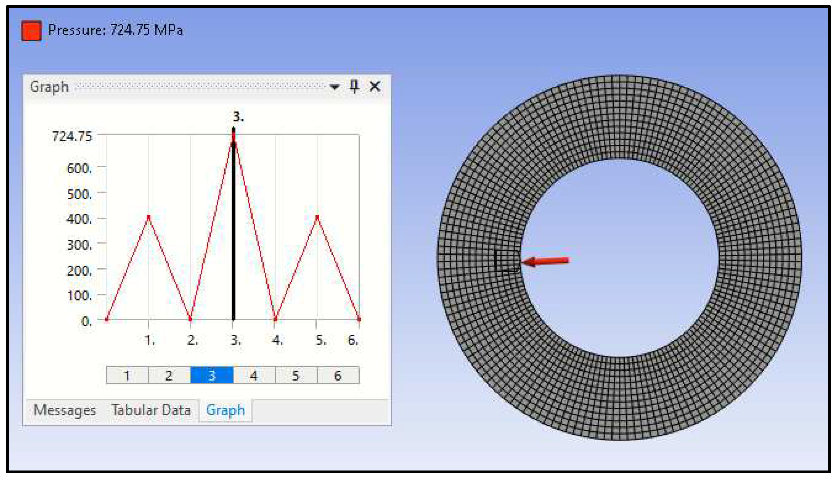
Figure 6.
Von-Mises Stress under 400 MPa Pressure.
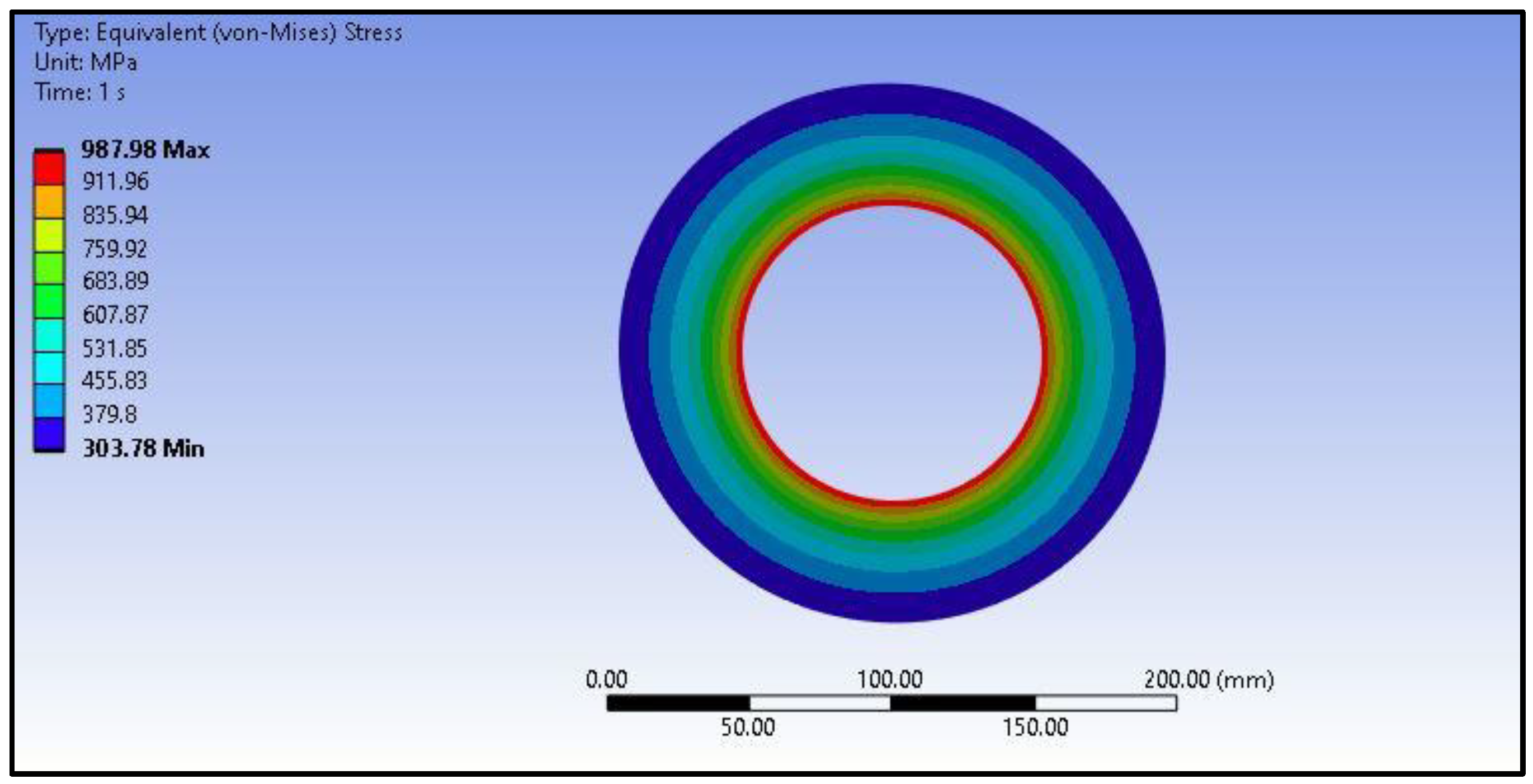
Figure 7.
Equivalent Plastic Strain when 400 Mpa Load is Removed.
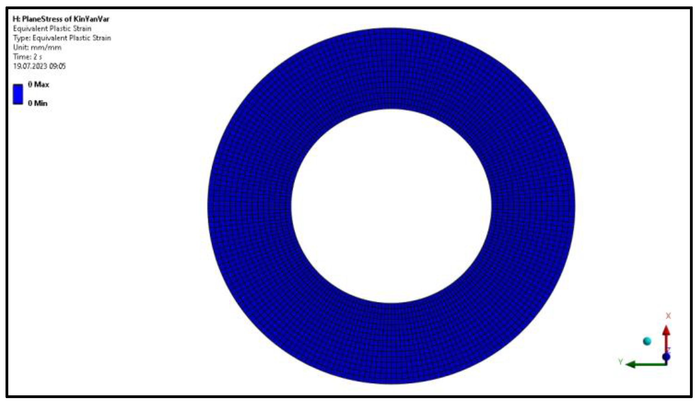
Figure 8.
Von-Mises Stress when Optimum Autofrettage Pressure is Applied.
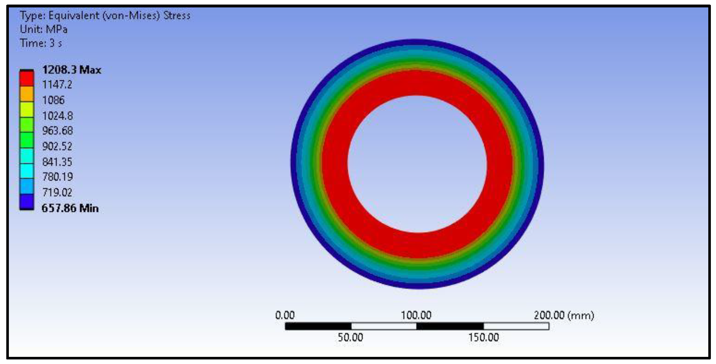
Figure 9.
Plastic Deformation and Stress Distribution when the Optimum Autofrettage Pressure is Removed.
Figure 9.
Plastic Deformation and Stress Distribution when the Optimum Autofrettage Pressure is Removed.

Figure 10.
Equivalent Plastic Strain after Optimum Autofrettage Pressure is Applied.
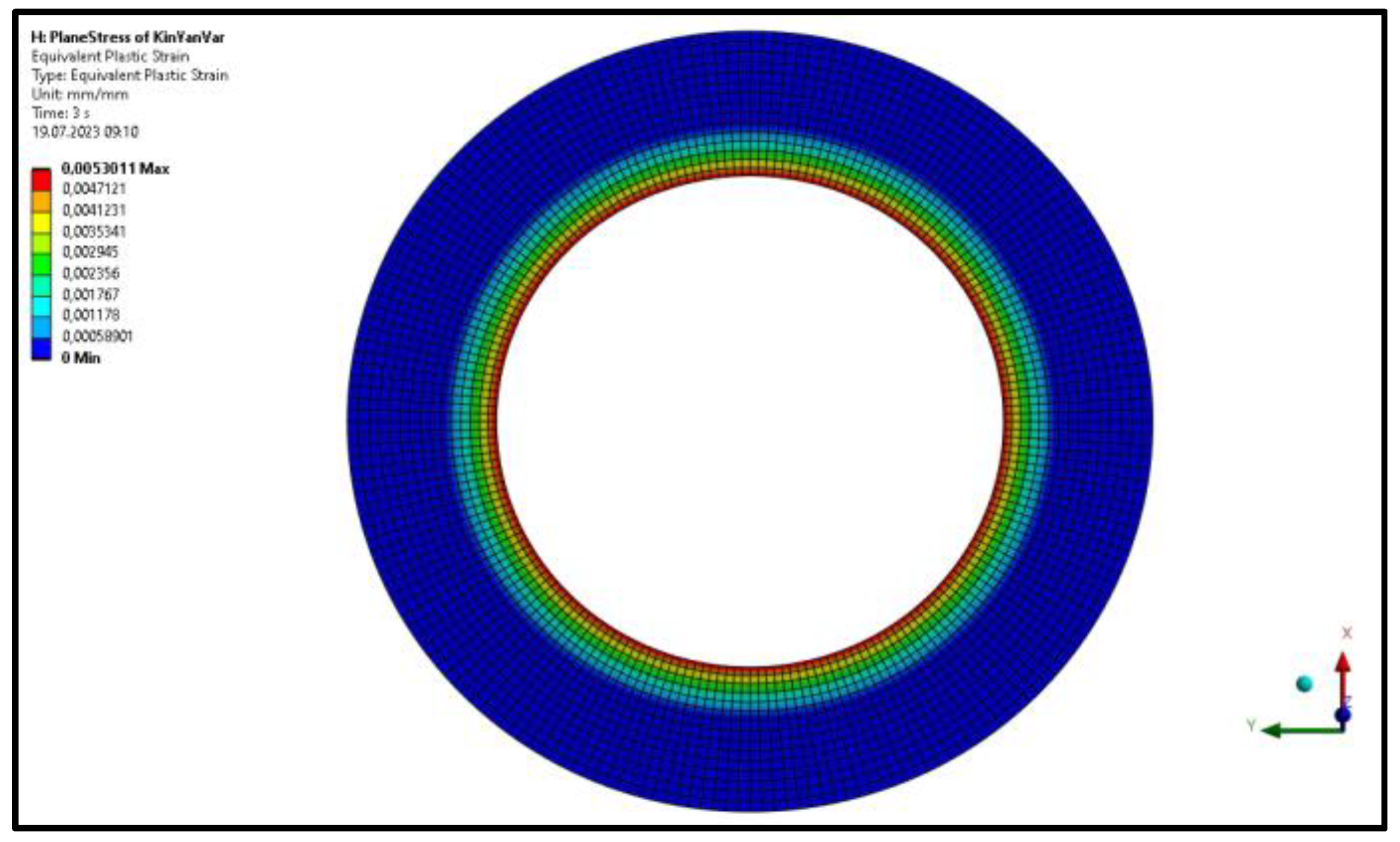
Figure 11.
Von-Mises Stress Distribution in Autofrettaged Barrel under Service Pressure.
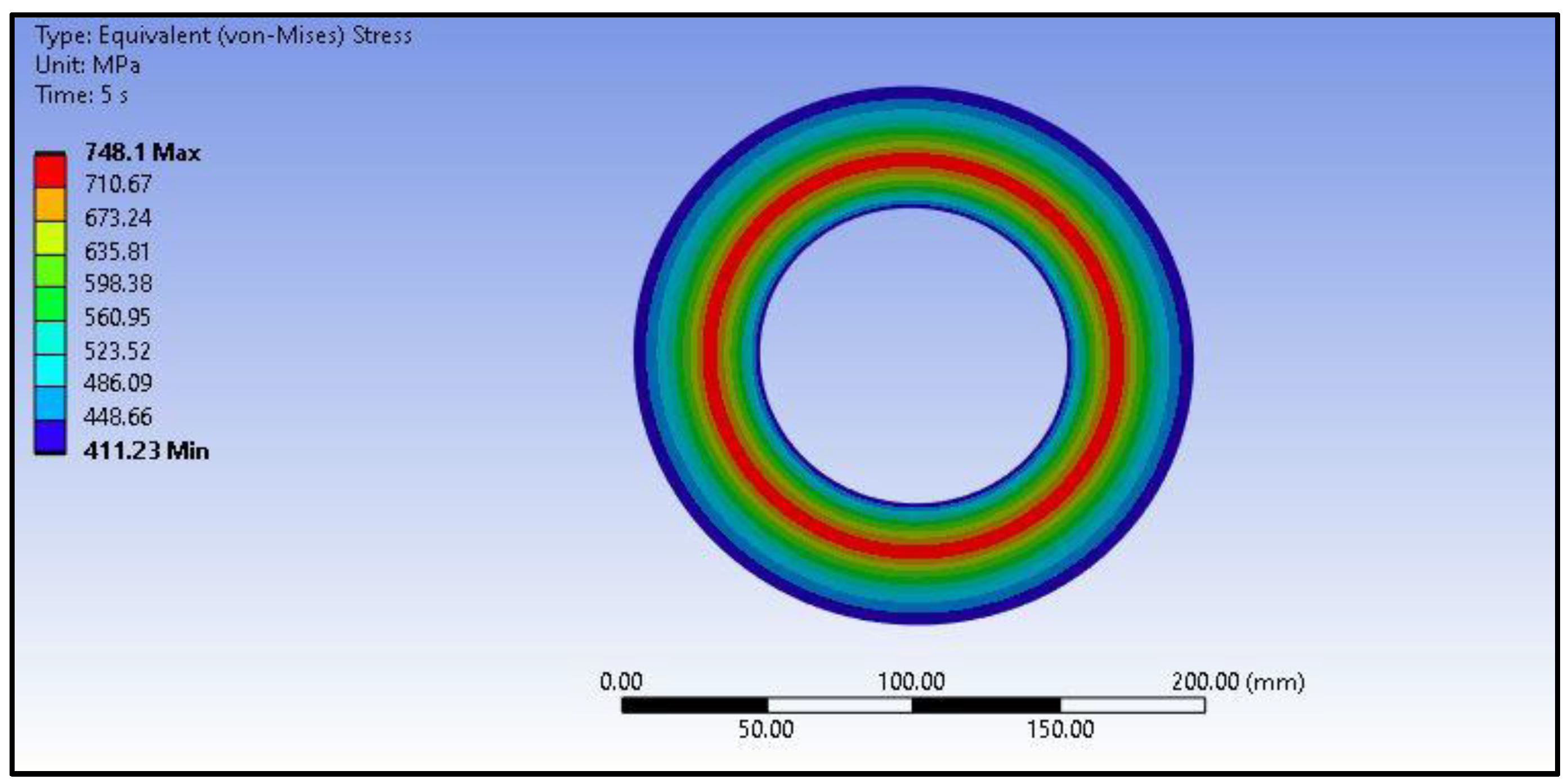

Table 1.
Chemical Composition Table of AISI 4340 [44].
Table 1.
Chemical Composition Table of AISI 4340 [44].
| Element | Ni | Cr | Mn | C | Mo | Si | S | P |
|---|---|---|---|---|---|---|---|---|
| Composition Percent (%) | 1.65-2.00 | 0.70-0.90 | 0.60-0.80 | 0.38-0.43 | 0.20-0.30 | 0.20-0.35 | 0.040 | 0.035 |
Table 2.
Mechanical Properties of the AISI 4340 Steel [45].
Table 2.
Mechanical Properties of the AISI 4340 Steel [45].
| Designation | Yield (Tension) | Yield (Compression) | Yield (Ultimate) | Tangent Modulus | Elastisity Modulus | Poisson’s Ratio |
|---|---|---|---|---|---|---|
| AISI 4340 Steel | 1200 (MPa) | 1130 (MPa) | 1270 (MPa) | 1489 (MPa) | 200 (GPa) | 0.3 |
Table 3.
Comparison of Analytical Results with the to Finite Element Analysis Results for Von-Mises Stress.
Table 3.
Comparison of Analytical Results with the to Finite Element Analysis Results for Von-Mises Stress.
| Analytical Results (MPa) | Finite Element Results (MPa) | |
|---|---|---|
| Inner Radius | 404.32 | 415.39 |
| Elactic-Plastic Radius | 749.55 | 748.10 |
| Outer Radius | 399.29 | 411.23 |
Disclaimer/Publisher’s Note: The statements, opinions and data contained in all publications are solely those of the individual author(s) and contributor(s) and not of MDPI and/or the editor(s). MDPI and/or the editor(s) disclaim responsibility for any injury to people or property resulting from any ideas, methods, instructions or products referred to in the content. |
© 2023 by the authors. Licensee MDPI, Basel, Switzerland. This article is an open access article distributed under the terms and conditions of the Creative Commons Attribution (CC BY) license (http://creativecommons.org/licenses/by/4.0/).
Copyright: This open access article is published under a Creative Commons CC BY 4.0 license, which permit the free download, distribution, and reuse, provided that the author and preprint are cited in any reuse.


