Submitted:
22 October 2023
Posted:
23 October 2023
You are already at the latest version
Abstract
The design of water Vessel fender system can minimize impact energy, which could result in severe vessel or offshore structure damage during collision. In order to protect Offshore structures and vessels from damage after impact, a Fender design approach is proposed which uses Soft materials like rubber, sand, inflated rubber tube, etc. to reduce damage on impacted vessels as well as offshore structures like wind turbines, bridges, oil drilling platforms in water etc. The fender is designed in such a way that it can handle vessels made of different material, sizes, and weights.The proposed solution is a fender consisting of a number of layers of soft sandwich materials, each layer getting softer as it moves away from the structure i.e. Hard-Soft fender design which can absorb impact energy upon collision. To handle lighter vessels made of soft or brittle materials, the outer layer is made of inflatable or Very soft foam rubber; however, the inner layer covering the offshore structure is made of hard material to handle heavy vessels made of hard material such as steel. Furthermore, the use of sand as a natural fender along waterways such as narrow channels is also proposed to reduce the cost of fender installation and catastrophic vessel impact damage on rocky ground since it produces less deformation just like rubber fender as demonstrated in the simulation. Finite Element Analysis using ANSYS software, Explicit Dynamic Autodyn, was performed. The results showed a considerable decrease in the total deformation and internal energy of the vessel and fended structure when collision occurs. Furthermore, the result showed that Hard-Soft fender layer performs much better than Soft-Hard-Soft followed by Soft-Hard Fender layer design.
Keywords:
Safety
; Collision
; Fender
; Finite Element Methods
; Structural Analysis
1. Introduction
1.1. Background
In water transport, often there is collision of vessel with vessel, vessel stranding or grounding [1,2], or collision of vessel with built structures [3] in water bodies such as wind turbines, or even collision on the edge of port during docking or in narrow waterways, for example a case that happened in the Suez Canal [4]. All these may result in some form of vessel structural damage, which may be mild or severe.
Structural analysis of an impacted vessel is very important for safety as well as a guide for the design and choice of suitable materials for the vessel's construction that can withstand forces that might result in catastrophic vessel damages, hence enhancing safety.
Due to this, several approaches to enhance the safety of vessel navigation have been proposed by many scholars to improve safety. For instance, bridge collisions, such as in the paper [5], in which several safety measures for collisions are proposed [6] to minimize the impact of vessel collisions with bridges,
1.1.1. Classification of Collision
There are basically two main classes of Ship collision [7,8]: 1) Vessel to Vessel Collision and 2) Vessel to Structure collision
Vessel to Vessel Collision is when ones Water Vessel Collides with another Vessel in water and they are categories as: Side collision, which is when a Vessel struck one side of another Vessel. Bow Collision is when there is head on Collison between two Vessels. Stern Collision normally happens when one Vessel runs into the back of another Vessel.
Allisions Collision is when a Vessel hit another structure on the water bodies.
There are also Vessel grounding which is when a Vessel hit the bed of the water body and also Vessel stranding as well.
Some of the most common causes of collision are attributed to Equipment failure, bad weather, and many more.
1.1.2. Methods for collision avoidance
1.1.3. Materials for Making Vessel
Water vessels are often made of different materials, and the degree of vessel damage after a collision can be affected by the type and property of the material it is made of. Here we discuss a few materials used for making water vessels.
Steel [12]: It’s one of the most commonly used types of material for shipbuilding and various large seagoing vessels due to its strength, durability, resistance to abrasion, and cost-effectiveness as well.
Aluminum, however, due to its low density and light weight, is commonly used for building small water vessels or high-speed vessels such as recreational boats, which gives them high buoyancy.
Fibre-reinforced plastic (FRP) and polyethylene are still new materials currently being used for boat building, and they too provide the same light weight as aluminum but with much less cost.
Wood, for example, teak wood, bamboo wood, and many more, have been in use for centuries. Their light weight and cost-effectiveness make them still in use. Up-to-date for boat making is especially common in hand-peddle fishing boats.
1.2. Problem Definition
During vessel collision with a structure, either the vessel or the structure or both suffer structural damage. Unfortunately, most currently available fenders do not perform well for some vessels made of some material type, weight, size, etc. So how best can we design a dynamic fender that can work for any vessel size, made of different materials, and hold varying load sizes, etc. without needing to change or redesign the fender?
1.3. Collision Scenario Design
In this paper, we examine the impact of a vessel made of different material, such as steel, aluminum, Wood, Fibre-Reinforced Plastic etc. When it collides with a steel structure built in water or grounding and stranding in a narrow water channel, like, for example, a case that happened in the Suez Canal, grounding on water bed soil (sand) or rock etc.
The collision can occur at different angles of vessel approach, such as (see figure 1). A work in [3] showed that the most severe angle of impact occurs at 90°, so throughout this text, emphasis is placed on material types of fender, structure, and vessel to determine which material produces more damage and the least damage from a vessel-fender-structure collision at 90°.
Figure 1 below on the left shows the angle of collision of a vessel with a built structure in water, i.e.,, a horizontal collision at an angle of 0° that is not included in the design. Also, on the right is the vessel stranding in a narrow water channel, like in the case of the Evergreen Cargo Ship in the Suez Canal, Egypt.
1.4. Relevant Literature Review
This sub-section discusses some of the most closely related work in the area of ways to minimize the impact energy during water vessels collision, such as fender design. Often, the most commonly and locally used fender type is the vehicle tire, which is placed sideways on the boat’s hull to protect the body when it comes into contact with another water vessel or during docking at port. However, it is placed above draught or draft (water level) of Ship to avoid drag force on the Vessel and this makes this fender type not effective for underwater purpose such as grounding or stranding.
The computer analysis of a Jumbo Hopper barge striking a frequently built fender was given in a publication by Wuttrich and others [13] to verify the crashworthiness of fender designs for bridges for potential retrofit, which they employ for further improving impact energy absorption.
The construction of steel fenders for bridge protection is a typical practice in China, according to Fan and colleagues' similar work in fender design [15]. The author's research, however, showed that when a steel fender of this type is involved in high-energy crashes, the impact forces and dynamics are frequently more than when there is no fender present. As a result, they suggested using a sandwich of steel and reinforced concrete, which lowers the impact energy.
The performance of pneumatic [16] fenders during side-by-side offloading operations was demonstrated in a work by Park and colleagues, who also carried out a comprehensive investigation of the kinetic energy absorption during impact collision.
The design and performance of rubber fender installation on a vessel for ship-to-ship collision were also analyzed using LS-DYNA in a research by Cho and colleagues [17], which demonstrated significant energy absorption.
Mozafari and colleagues [18] conducted a study that demonstrated the superior energy absorption capabilities of lightweight foam sandwich structures. They suggested a metallic foam shell (MFS) device, which has outstanding mechanical qualities and is low in density. They further pointed out that closed-cell aluminum foam performed best in terms of energy absorption capacity during an impact on the offshore wind turbine fenders.
Last but not least, a study by Qasim and colleagues [19] investigated the impact of a heavy vessel on a cylindrical rubber fender having an inner radius of 0.25m and an outer radius of 0.5m during berthing or mooring; their findings demonstrated significant impact energy absorption.
2. Materials and Methods
Here below (see Table 1), we provide a few material properties that are used to build the model of the structure, vessel, and fender.
Styrene butadiene rubber , Sand , Natural Rubber , Pure Aluminum , Steel , Reinforced Concret , Carbon Fibre-Reinforced Plastic , Auxetic Low density Polyethylene , Bamboo Wood , and Soft Foam Rubber [20,21] and closed Aluminium foam (regular, stack cell foam) [22].
Both natural and synthetic elastomers are available for compounding into rubber products. The American Society for Testing and Materials (ASTM) classification and composition of a few common elastomers are shown in Table 33.1 of the study [23]. High-regularity elastomers include butyl rubber, natural rubber, and neoprene.
2.1. Sandwich Layer Fender Design
2.1.1. Soft-Hard-Soft Fender design
In this proposed methods, a design approach is presented (see Figure 2) where it is assumed that to protect a structure from collision, and Vessel as well, both requires some form of soft fender which can absorb kinetics impact energy during collision, however because the challenges which was pointed out in sub-section introduction shows that there are Vessel made of different materials and of different sizes(weight), these requires that the fender design need to be effective enough to handle such different Vessel, else it may perform well for a certain Vessel type and may not for other type for instance a fender design for Steel Cargo Vessel may not work for light Passenger small Vessel made of brittle or soft material such as aluminum or Fibre-Reinforce Plastics etc.
So, the design is in a way that the softest material is placed outside and sandwich with a soft material, up to hard material in the middle, the trend of softness decreases again up to the softest on the other side as shown in the figure 2. In figure 2, there are three layers sandwich the first layer on the structure is soft, flowed by hard layer in the middle, then last outer lay is soft again, these ensure that impact energy is distributed equally on the structure as well as the Vessel.
In the equation set of layers of fender below see (1) shows the pair of fenders whose material should be the same and in the above design, the total layers of sandwich fender layers should be an odd number to ensure balance in distribution of the fender layer material on either side.
Supposes we have, so from equation (1), the set of material can be so every pair of layer in the bracket should have the same material type to ensure balance. And for seven layers as used here for testing purpose..
In Figure 3 (a) below shows five layers straight edge fender in order of soft-hard-soft and (b) is circular 5-layer fender in order of soft-hard-soft layers.
2.1.2. Hard-Soft Layer Fender Design
In this sub-section, a design approach is also proposed in which layers of fender start from hard material covering structure up to the soft material from outside.
Figure 4 below shows a fender design with different layers sandwiched covering the wall of a reinforced concrete or steel structure in water. Layer 1 is made of hard material like for instance sand; layer 2 is made of softer material than layer 1 for instance rubber, layer 3 is made of softer material than layer 2 e.g., foam; this continues up to the outer last layer, which should in general be very soft and made of material like inflatable rubber or very soft rubber foam. This layout enable small Vessel made of soft or brittle material not to crash when it collides with a structure.
The above design in figure 4, (a) image 1, is suitable for straight-edge structures such as at ports, rectangular structures, etc., but for circular structures figure 4. (b) like pillars for offshore wind turbine structures, we can modify it such that the fender can rotate around the structure with a roller, which is also a fender.
2.1.3. Soft-Hard Layer Fender
Just like in figure 4 where the layer starts with hard material from the structure to the soft material outside, in Soft-Hard is the opposite of the design in figure 4 where instead soft material is placed inside covering the structure followed by an intermediate material up to the hard material outside.
2.2. Sand Fender Design
The design of a fender layer as discussed above can at times be very costly or tiresome to install in every situation, especially in very long, narrow waterways like rivers and canals where the water bed or edge is covered with hard material such as rock. This can cause damage that can be severe whenever vessel grounding or stranding occurs, just like for an example of the Evergreen cargo ship that got stuck in the Suez Canal. There are many naturally occurring materials in water bodies, like sand [24], which can act as a natural fender towards this rocky bed. So, a suggestion to remove rock from the waterway and fill it with sand during dredge work would be a very cost-effective fender solution against grounding or stranding (see Figure 5).
3. Results
3.1. Test Simulation Condition
The following conditions were set for the test simulation including software and hardware used for test simulation.
Software used for Simulation; ANSYS software for simulation: ANSYS Student Version 2023 R1
Explicit Dynamics; Solver: Autodyn; Mesh element size: 0.3m; reference energy: 9999999; End time: 0.4 s; Velocity of vessel: 3 m/s (direction towards the fender); Angle of impact; one fixed support on the structure from behind; Geometry design was performed using SpaceClaim. Attached are the geometry files that include all the measurements. See figure 6 (a) below for the sample geometry design images captured and mesh (b).
The first image in Figure 6 (a) is of a five layer’s fender and figure 6 (b) is the image of the generated mesh with a mesh element size of 0.3m.
Structure’s dimension is in the order of width(m) by height(m) by Length (m)
Fender also having same dimensions as the structure however for five layers, it is divided into five equal parts with each having an equal dimension as in the order of width(m) by height(m) by Length (m).
Computer Configuration used for this simulation; Processor: Intel(R) Quad Core (TM) i7-4790 CPU @ 3.60GHz 3.60GHz; OS: window 10, Memory: RAM 8GB.
3.2. Result and Data Presentation
Table 3 and 4 below shows data of different deformations in meters performed at an angle of vessel impact of 90° (see figure 1). With different fender designs in Figure 2 having five layers of sandwich materials as shown in Figure 3 and figure 4. Table 2 shows those layer each assign a material property and Table 3 and table 4 shows data obtained from simulation from ANSYS. The vessel is made of different materials i.e., Steel, Aluminum, Bamboo wood, Polyethylene and a fender design made of three material sandwich into five layers , so in between the Steel structure and the vessel is placed a fender design, and total deformation in meters is calculated using ANSYS Explicit Dynamic software using the AutoDYN solver. The table data is organized in form as {total deformation of vessel}, {total deformation of structure}, where in between is placed a fender.
Here we use five layers of fender for experimental purposes. So, from equation 1, five layers can be divided into as follows each pair of layers having same material property see Table 2. Fender shows fender layer sandwich of material. For the purpose of testing which layer design has better kinetic energy absorption, we put fender design
3.2.1. Total Deformation Data
In Table 3. Shows total deformation of Vessel and Structure after impact, however unlike in Table 4, in Table 3, there is only one layer of fender however this one layer has the same geometrical measurement as that of sandwich five layers in Table 4. This is just to show the behavior of the material being use as a fender in fender layer design.
In Table 4. Below, is the total deformation of the Vessel and Structure in meter for fender design with layers as presented in Table 2.
Simulation results in table 4 is meant for testing which position would be ideal for placing hard material sandwich in the layer fender design i.e., left, right or in the middle? And also, for showing that sandwich fender material is as effective as non-sandwich material although they are more effective for handling Vessel of Various types.
The author's research in [14], however, showed that when a steel fender of this type is involved in high-energy crashes, the impact forces and dynamics are frequently more than when there is no fender present. As a result, they suggested using a sandwich of steel and reinforced concrete, which lowers the impact energy. So here we added Styrene butadiene rubber Fender as the third layer on either side and we test the position of the hard layer to see the best optimal layering of the fender sandwich (see Table 4) for the result.
3.2.2. Internal Energy Data
This section presents data about changes in the internal energy of a body after a collision. It is known that when a body gains energy from its external forces, it results in an increase in its internal energy level. Now in this case, we assume that when a vessel is traveling at a given velocity, it possesses kinetic energy. Upon collision, this kinetic energy is converted into various forms of energy, such as heat energy, which raises the internal energy of the vessel. Also, because it collides with the fender, some energy is transmitted to the fender and some passes to the structure.
Overall, a better fender should be able to absorb some of this kinetic energy, resulting in a lower increase in both the vessel's and structure’s internal energy.
In Table 5, below is data on the internal energy in joules of the vessel and structure as well.
In Table 6, Below is data on the internal energy of the vessel and the structure covered by fender, which has different layers, i.e., five layers sandwiched together to form a single fender. However, the sequences of layers are altered, as shown in Table 2. To test the order of the sandwiched layers, which gives optimal energy absorption.
4. Discussion and Analysis
From Table 3, above, the data of a fender with single layer obtained from ANSYS software simulation shows that a rubber fender results in lower vessel deformation compared to fender made of material such as Sand, Concrete and steel.
Because aluminum is softer than steel, the vessel experiences more deformation than its steel counterpart. Also, because aluminum vessels are lighter than steel vessels, less impact energy is transmitted through the fender to the structure compared to steel vessels. This goes on for other Vessel material such as Polyethylene, and Bamboo wood. Vessel made of these experiences very high deformation when they collide with steel or Reinforced concrete structure with exception of polyethylene and Bamboo wood when they collide with concrete and steel respectively, which they show slightly less deformation compare to other material.
In comparison, in table 3. Sand fenders also act well as fenders, as the deformation of both steel, aluminum, Polyethylene and Bamboo wood vessels is relatively equal to that of rubber fenders, although slightly higher. Also, sand appears to protect structures slightly better than rubber, as less impact energy is transmitted through sand to the structure.
In Table 4. contains data of multiple layers (5) fender having different materials. The purpose of this data is for finding out if multiple layer of fender having sandwich of material layer have good energy absorption upon collision just like or better than rubber? The answer is definitely yes as evidenced in Table 4.
And in what way should the arrangement of the layer material be placed to obtained an optimal kinetic energy absorption to minimize damages after collision.
The data in Table 7 and Figure 8. shows that Hard-Soft layer fender design overall is better at protecting Vessel and structure which produces less impact deformation followed by Soft-Hard layer fender design and last, is Soft-Hard-Soft layer fender. However Soft-Hard-Soft layer fender design is overall better at protecting Vessel made of hard material such as steel.
In this simulation, only five layers of fender were used and no air inflated soft layer was used, and this resulted in very small performance improvement values; however, to get reasonable results, more layers of fender should be added from the outside with the outer layer should be very soft i.e., inflated or very soft foam. Also, the results weren’t very accurate as a student version of ANSYS software was used, which doesn’t permit use of higher nodes (large element size). But the most important is the trend that is derived from the data.
5. Conclusions
The following are the conclusive remarks drawn from the data obtained from simulation using ANSYS Explicit Dynamic (Autodyn).
From Table 3, sand is a very good fender, which is as good as rubber fender, but unlike rubber, sand in water can easily deform but cannot regain its original shape like rubber making it not fit for reuse and other Vessel made of softer material do experience more deformation when it collides with sand fender. So, making it fit for Vessel made of hard material like Steel, Aluminum etc. as demonstrated in table 3 simulation data.
From Table 4, making sandwich of fender layers in the order of Hard-soft, Soft-Hard and soft-hard-soft fender layers minimizes damages and impact kinetic energy during collisions on structure and vessel respectively. These ensure that Vessel made of different material and having different weight can be protected using the same fender. Howeevr table 7 and figure 8. shows that overall Hard-Soft design performed much better, followed by Soft-Hard then least least is Soft-Hard-Soft design.
To ensure considerable energy absorption during collision for layer fender that can protect vessels made from different materials such as wood, aluminum, and steel, polyethylene , etc. the inner layer of the fender should be made of materials that can absorb much energy from Vessel made of heavy/hard materials like steel, and the outer last layer of the fender should be made of materials like air-filled or foam-filled rubber, which can absorb impact energy from light vessels made of soft or brittle materials.
Supplementary Materials
The following supporting file containing 1. Geometry Design of collision scenario in Space Claim in ANSYS version 2023 R1, 2. Excel file for data and graph can be obtained upon request from the corresponding author. Or downloaded from google drive link at: https://drive.google.com/drive/folders/1foXa8UTqQKJpelqH9ZQshj3l78Xj_xI-?usp=drive_link.
Abbreviation
|
FEA FEM Vs |
Styrene butadiene rubber Sand Natural Rubber Aluminum Steel Reinforced Concrete Carbon Fibre-Reinforced Plastic Auxetic Low density Polyethylene Bamboo Wood Soft Foam Rubber Finite Element Analysis Finite Element Method Water Vessel Closed Cell Aluminum Foam Fender design layer Hard-Soft Fender design layer Soft-Hard-Soft Fender design layer Soft-Hard |
References
- Hong, L. (2009). Simplified analysis and design of ships subjected to collision and grounding.
- Liu, B.; Soares, C.G. Simplified analytical method for evaluating web girder crushing during ship collision and grounding. Mar. Struct. 2015, 42, 71–94. [Google Scholar] [CrossRef]
- Song, M.; Jiang, Z.; Yuan, W. Numerical and analytical analysis of a monopile-supported offshore wind turbine under ship impacts. Renew. Energy 2020, 167, 457–472. [Google Scholar] [CrossRef]
- Stranded Ship in Suez Canal: https://www.marca.com/en/lifestyle/world-news/2023/01/09/63bc12c8e2704eb50b8b45d1.
- Kunz, C. U. (2017). Ship bridge collision in river traffic, analysis and design practice. In Ship collision analysis (pp. 13-21). Routledge.
- Wang, J.; Song, Y.; Wang, W.; Chen, C. Evaluation of flexible floating anti-collision device subjected to ship impact using finite-element method. Ocean Eng. 2019, 178, 321–330. [Google Scholar] [CrossRef]
- Pedersen, P.T. Review and application of ship collision and grounding analysis procedures. Mar. Struct. 2010, 23, 241–262. [Google Scholar] [CrossRef]
- Haris, S.; Amdahl, J. Analysis of ship–ship collision damage accounting for bow and side deformation interaction. Mar. Struct. 2013, 32, 18–48. [Google Scholar] [CrossRef]
- Huang, Y.; Chen, L.; Chen, P.; Negenborn, R.R.; van Gelder, P.H.A.J.M. Ship collision avoidance methods: State-of-the-art. Saf. Sci. 2020, 121, 451–473. [Google Scholar] [CrossRef]
- Namgung, H.; Ohn, S.-W. Fuzzy Inference and Sequence Model-Based Collision Risk Prediction System for Stand-On Vessel. Sensors 2022, 22, 4983. [Google Scholar] [CrossRef] [PubMed]
- Wang, B.; He, Y.; Hu, W.; Mou, J.; Li, L.; Zhang, K.; Huang, L. A Decision-Making Method for Autonomous Collision Avoidance for the Stand-On Vessel Based on Motion Process and COLREGs. J. Mar. Sci. Eng. 2021, 9, 584. [Google Scholar] [CrossRef]
- VanDerHorn, E. , & Wang, G. ( 2011). A statistical study on the material properties of shipbuilding steels. Sustainable Maritime Transportation and Exploitation of Sea Resources, 371–378.
- Wuttrich, R.; Wekezer, J.; Yazdani, N.; Wilson, C. Performance Evaluation of Existing Bridge Fenders for Ship Impact. J. Perform. Constr. Facil. 2001, 15, 17–23. [Google Scholar] [CrossRef]
- Fan, W.; Yuan, W.; Chen, B. Steel Fender Limitations and Improvements for Bridge Protection in Ship Collisions. J. Bridg. Eng. 2015, 20. [Google Scholar] [CrossRef]
- Park, S.M.; Kim, H.J.; Cho, H.R.; Kong, K.H.; Park, D.K.; Paik, J.K. Effect of pneumatic rubber fenders on the prevention of structural damage during collisions between a ship-shaped offshore installation and a shuttle tanker working side-by-side. Ships Offshore Struct. 2022, 18, 596–608. [Google Scholar] [CrossRef]
- Sakakibara, S. , & Wan, M. (2003, May). Evaluation of Prototype Confirmation Test for Floating Pneumatic Rubber Fenders Based on ISO17357. In ISOPE International Ocean and Polar Engineering Conference (pp. ISOPE-I). ISOPE.
- Cho, H.R.; Kim, H.J.; Park, S.M.; Park, D.K.; Yun, S.H.; Paik, J.K. Effect of solid rubber fenders on the structural damage due to collisions between a ship-shaped offshore installation and an offshore supply vessel. Ships Offshore Struct. 2022, 18, 1037–1059. [Google Scholar] [CrossRef]
- Mozafari, H.; Distefano, F.; Epasto, G.; Gu, L.; Linul, E.; Crupi, V. Design of an Innovative Hybrid Sandwich Protective Device for Offshore Structures. J. Mar. Sci. Eng. 2022, 10, 1385. [Google Scholar] [CrossRef]
- Qasim, A. , Anis, A., & Mohamad, J. (2017). Evaluate the Cylindrical Rubber Fender Response Under Dynamic Load. In Seventh International Conference on Advances in Civil and Structural Engineering-CSE.
- Patel, P.S.; Shepherd, D.E.; Hukins, D.W. Compressive properties of commercially available polyurethane foams as mechanical models for osteoporotic human cancellous bone. BMC Musculoskelet. Disord. 2008, 9, 137–137. [Google Scholar] [CrossRef] [PubMed]
- Anggaravidya, M.; Amry, A.; Arti, D.K.; Kalembang, E.; Susanto, H.; Hidayat, A.S.; Limansubroto, C.D. Properties of Natural Rubber/Chloroprene Rubber Blend for Rubber Fender Application: Effects of Blend Ratio. Macromol. Symp. 2020, 391. [Google Scholar] [CrossRef]
- Wan, X.; Zhu, K.; Xu, Y.; Han, B.; Jing, T. Early Compressive Deformation of Closed-Cell Aluminum Foam Based on a Three-Dimensional Realistic Structure. Materials 2019, 12, 1792. [Google Scholar] [CrossRef] [PubMed]
- Schaefer, R. J. (2010). Mechanical properties of rubber. Harris' Shock and Vibration Handbook, Sixth edition, A. Piersol, T. Paez (Eds), McGraw-Hill Companies Inc, 33-1.
- Prokon (2022, Feb) Properties of Soil, https://www.prokon.
Figure 1.
(a) is the vessel’s angle of collision with a structure, and (b) is a stranded vessel in a narrow channel.
Figure 1.
(a) is the vessel’s angle of collision with a structure, and (b) is a stranded vessel in a narrow channel.
Figure 2.
Shows Soft-Hard-Soft Fender design for both Straight and Circular Structure.
Figure 3.
Shows both Soft-Hard-Soft 3D fender design for Straight (a) and circular (b) Structure.
Figure 4.
Shows Hard-Soft 3D fender design for both Straight edge (a) and circular (b) Structure.
Figure 5.
Shows Sand layer 1 used as Fender covering a Rocky Structure.
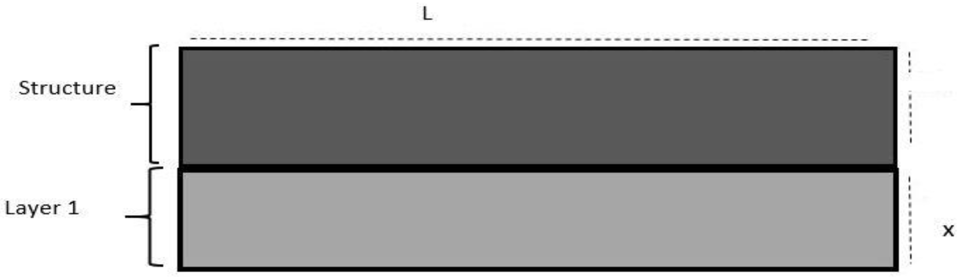
Figure 6.
Shows SpaceClaim Geometry Design of Collision scenario with Fender (a) and Generated Mesh (b).
Figure 6.
Shows SpaceClaim Geometry Design of Collision scenario with Fender (a) and Generated Mesh (b).
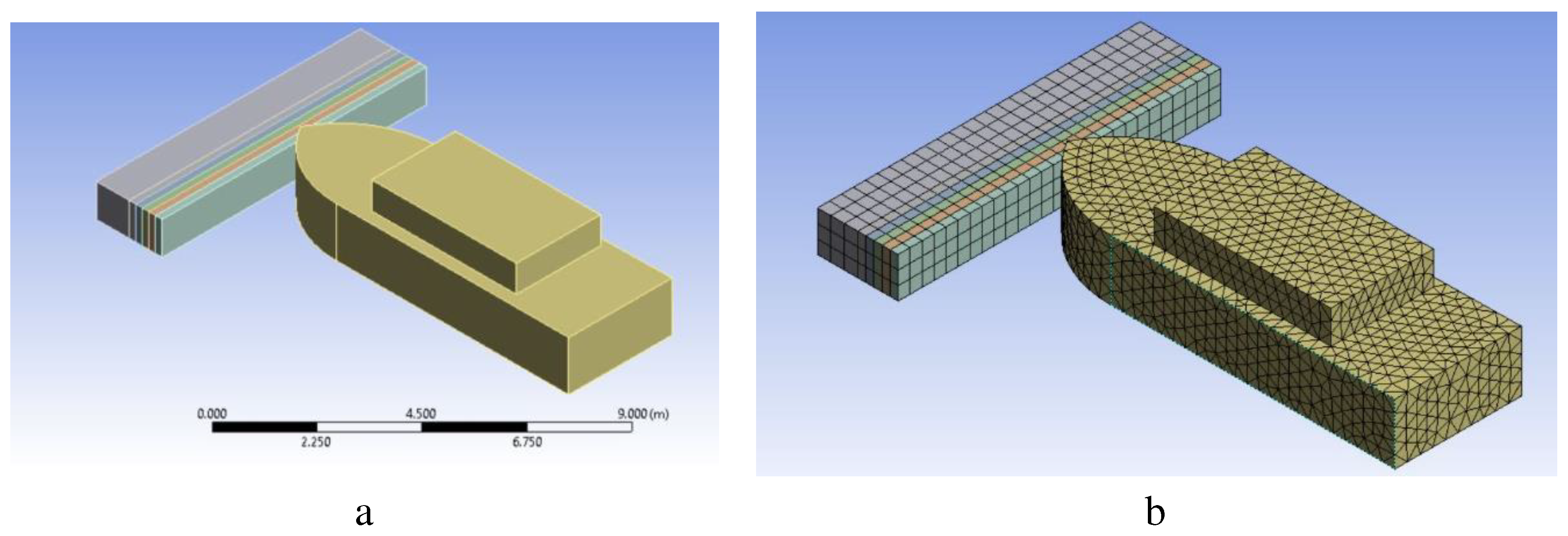
Figure 7.
Shows sample Simulation images from ANSYS of Vessel’s Collision with Structure.
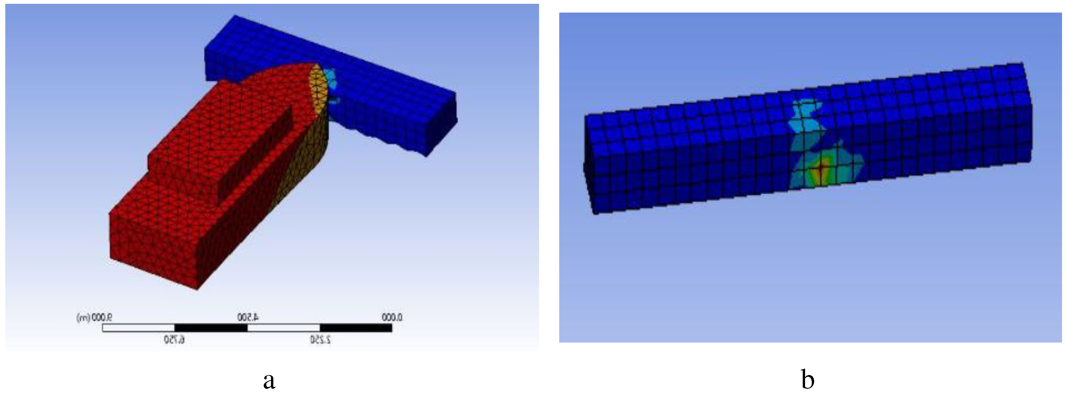
Figure 8.
Shows internal Energy changes of (a) Vessel and (b) Structure.
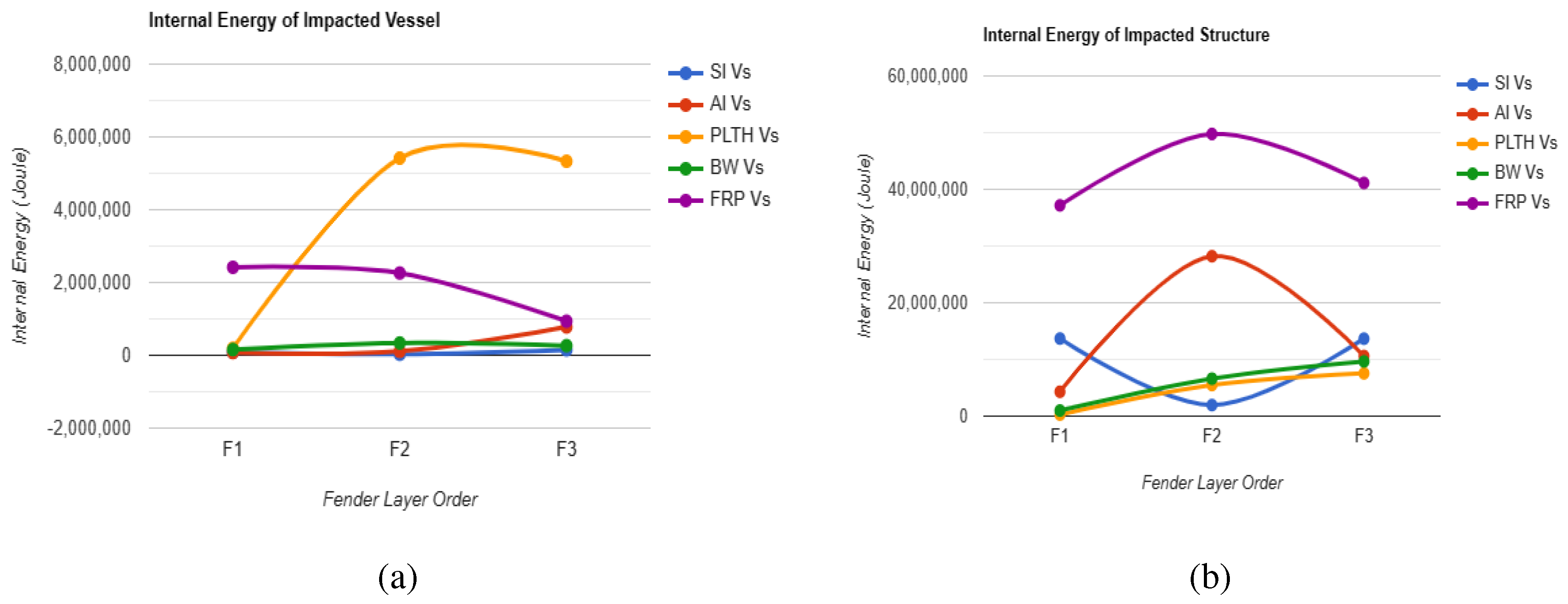

Table 1.
Shows Material properties used in building the model.
| Material Properties | RC | |||||||||
| Poisson Ratio | 0.34 | 0.45 | 0.4999 | 0.496 | 0.31 | 0.28 | 0.2 | 0.486 | -0.32 | 0.25 |
| Density () | 410 | 1922 | 1340 | 1220 | 2700 | 7800 | 2400 | 1500 | 925 | 1150 |
| Elastic Module (GPa) | 0.44 | 0.0889 | 0.003 | 0.002 | 62 | 200 | 38 | 124 | 1.08 | 28 |
These materials are used for the design of vessels, such as those made of aluminum, steel, etc., and also for offshore structures like wind turbines and many more.
Table 2.
Shows the arrangement of fender five layers used in the design.
| Fender Design | Layer 1 | Layer 2 | Layer 3 | Layer 4 | Layer 5 |
|---|---|---|---|---|---|
| Fender | |||||
| Fender | |||||
| Fender |
Table 3.
Total Deformation (m) of {Vessel} and {Structure} single fender layer with different material.
Table 3.
Total Deformation (m) of {Vessel} and {Structure} single fender layer with different material.
| Vessel’s Material |
Fender |
Fender |
Fender |
Fender |
Fender |
Fender |
| Steel Vessel | {1.2007} {0.0239} |
{1.2017} {0.0295} |
{1.2052} {0.0433} |
{1.2487} {0.0161} |
{1.2582} {0.1047} |
{1.3525} {0.1515} |
| Aluminum Vessel | {1.2038} {0.0214} |
{1.2056} {0.0352} |
{1.2081} {0.0473} |
{1.2541} {0.0120} |
{1.5832} {0.0414} |
{3.7425} {0.0576} |
| Polyethylene Vessel | {1.2148} {0.0058} |
{1.2127} {0.0074} |
{1.4353} {0.0045} |
{1.3069} {0.0041} |
{1.2642} {0.0381} |
{1.2999} {0.0468} |
| Bamboo Wood Vessel | {1.2098} {0.0188} |
{1.2135} {0.0078} |
{1.3621} {0.0210} |
{1.3109} {0.0101} |
{4.3618} {0.0218} |
{1.3521} {0.0964} |
Table 4.
Data of Total Deformation of {Vessel} and {Steel Structure} in meter for multi-layer Fender.
Table 4.
Data of Total Deformation of {Vessel} and {Steel Structure} in meter for multi-layer Fender.
| Vessel’s Materials | Deformation |
||
|---|---|---|---|
| Steel Vessel | {1.2060} {0.0254} |
{1.1633} {0.0070} |
{1.2019} {0.0276} |
| Aluminum Vessel | {1.2154} {0.0230} |
{1.2066} {0.0331} |
{1.2075} {0.0270} |
| Polyethylene Vessel | {1.2162} {0.0079} |
{1.2160} {0.0350} |
{1.2511} {0.0359} |
| Bamboo Wood Vessel | {1.2150} {0.0106} |
{1.2133} {0.0248} |
{1.2111} {0.0243} |
| Fibre-Reinforced Plastic Vessel | {1.2121} {0.0437} |
{1.2096} {0.0395} |
{1.2058} {0.0462} |
Table 5.
Shows Max Internal Energy of {Vessel} and {Structure} for Single layer Fender.
| Vessel’s Material |
Fender |
Fender |
Sand Fender |
Fender |
Concrete fender |
Steel fender |
|---|---|---|---|---|---|---|
| {75524} {9.582e+6} |
{67900} {8.6952e+6} |
{7.1033e+5} {9.4429e+6} |
{5.268e+5} {6.9668e+6} |
{1.0135e+8} {3.5336e+8} |
{2.9709e+9} {2.4019e+9} |
|
| {1.2986e+5} {3.8768e+6} |
{4.249e+5} {4.4977e+6} |
{3.5819e+6} {4.597e+7} |
{6.3544e+5} {2.5211e+6} |
{9.0029e+8} {2.5474e+8} |
{3.5883e+9} {8.2965e+9} |
|
| {1.8402e+5} {94007} |
{2.6244e+5} {2.396e+5} |
{1.8912e+6} {1.4105e+5} |
{2.0898e+6} {3.4399e+5} |
{9.482e+7} {2.008e+7} |
{2.6566e+8} {1.5856e+7} |
|
| {3.2249e+5} {2.2145e+6} |
{58149} {6.706e+5} |
{4.4536e+5} {1.4998e+6} |
{9.6573e+5} {1.3059e+6} |
{8.2743e+7} {7.559e+7} |
{4.3531e+8} {7.3841e+8} |
Table 6.
Data of Total Internal Energy of {Vessel}, {Structure} in Joule for five Layer Fender.
| Vessel’s Materials | |||
|---|---|---|---|
| Steel Vessel | {84810} {1.3685e+7} |
{28427} {1.9494e+6} |
{1.4785e+5} {1.3659e+7} |
| Aluminum Vessel | {74022} {4.2979e+6} |
{1.1e+5} {2.8207e+7} |
{7.7811e+5} {1.06e+7} |
| Polyethylene Vessel | {1.9406e+5} {2.7312e+5} |
{5.4173e+6} {5.4834e+6} |
{5.3315e+6} {7.5456e+6} |
| Bamboo-Wood Vessel | {1.5805e+5} {9.8683e+5} |
{3.3808e+5} {6.6014e+6} |
{2.6546e+5} {9.6457e+6} |
| Fibre-Reinforced Plastic Vessel | {2.4172e+6} {3.7171e+7} |
{2.2602e+6} {4.977e+7} |
{9.3645e+5} {4.1128e+7} |
Table 7.
Average Values for Internal Energy and Deformation of Vessel and Structure.
| Average Mean Value of | |||
|---|---|---|---|
| Internal Energy of Vessel | 585628.4 | 1630801 | 1.49E+6 |
| Internal Energy of Structure | 1.13E+7 | 1.84E+7 | 1.65E+7 |
| Deformation of Vessel | 1.2129 | 1.2018 | 1.2155 |
| Deformation of Structure | 0.0221 | 0.0279 | 0.0322 |
Disclaimer/Publisher’s Note: The statements, opinions and data contained in all publications are solely those of the individual author(s) and contributor(s) and not of MDPI and/or the editor(s). MDPI and/or the editor(s) disclaim responsibility for any injury to people or property resulting from any ideas, methods, instructions or products referred to in the content. |
© 2023 by the authors. Licensee MDPI, Basel, Switzerland. This article is an open access article distributed under the terms and conditions of the Creative Commons Attribution (CC BY) license (https://creativecommons.org/licenses/by/4.0/).
Copyright: This open access article is published under a Creative Commons CC BY 4.0 license, which permit the free download, distribution, and reuse, provided that the author and preprint are cited in any reuse.


