Submitted:
14 October 2023
Posted:
18 October 2023
You are already at the latest version
Abstract
In the present study, an epoxy-modified silica nano-composite coating was deposited on an aluminum substrate and ACSR conductor. For this purpose, super-hydrophobic modified silica nanoparticles based on the TEOS and MTES precursors were prepared. Then, the modified silica nanoparticles were added to the epoxy resin solution. The coating deposition on an aluminum substrate and ACSR conductors was performed by a spraying method. The structure, morphology, and chemical analysis of the nanoparticle’s surface were studied with X-ray diffractometer (XRD), Transmission electron microscopy (TEM), and Attenuated Total Reflectance Fourier Transform Infrared (ATR-FTIR) methods. The water contact angles on the prepared samples were measured by a water contact angle analyzer method. Icing tests were performed at a constant operating temperature of -14 °C. Also, the self-cleaning behavior of the samples was evaluated with an iron oxide powder. The results indicated that the epoxy-modified silica nano-composite coating showed hydrophobic (CA, 141°), anti-icing, and self-cleaning properties.
Keywords:
SiO2
; hydrophobic
; Anti-icing
; Self-cleaning
; protective coatings
1. Introduction
Icing is one of the most important problems of the power industry in cold regions. Accumulation of snow and ice on power transmission lines leads to their destruction. many countries such as Canada, England, China, Norway, America, Iran, etc. are involved in the effects of icing [1,2,3,4,5,6,7,8,9].
In January 1998, a major ice storm caused severe damage to power network equipment in eastern Canada and the northeastern United States. In fact, from the 4th to the 10th of January, freezing rain fell for about 80 h. At the height of the storm, 1.4 million people were without power. The storm caused unprecedented damage to 3000 km of power lines, 4000 power transformers and 1000 steel towers. The power outage lasted for 4 weeks and caused 6.4 billion dollars damages [1]. In February 1999, the 400-130 kV power grid in southwestern Sweden was affected by an ice storm. The accumulation of ice in the insulators near the coast caused a fire and a number of 130-400 kV power lines failed at the same time [2]. In another incident, a 130 KV insulator near the coast caused a power outage, however, this incident was not the result of a fire, but the weather caused severe icing of the insulator. In the coastal area, the winds coming from the coast carry salt particles with them and cause insulation pollution. To solve this problem, automatic washing was done in the 400 kV insulator, but the temperature in that area dropped, and heavy snow fell and the insulator failed due to severe icing [3]. Severe icing events cause major disturbances in England, which happen almost every few years. In 1990, heavy snow caused a decrease in the voltage of 400 kV lines. Some cities had power outages for 30 h, and more than a million customers were affected as the storm moved from north to south. In addition, some customers were without electricity for 9 days. The icing affected Scotland and North Wales, and ice thickness with a radius of 200 mm was created on power lines [4]. In 2010, heavy snowfall was recorded in the coastal area called Costa Brava. This phenomenon was with a snowfall rate of 1 mm/min, which included large snow grains, because the height of the area was below 500 m from the sea level. Such weather was unexpected and transmission towers were not designed for such weather. This caused an additional load on power lines and power grid towers and destroyed the network, and it was estimated that 200,000 customers were damaged by the power outage. It took six weeks for the company to restore the power grid to normal. This company suffered heavy financial losses and had to redesign the power lines with a focus on ice loads [5]. In 1961, the world’s largest ice storm was observed on an overhead conductor in Norway, where the icing snow on one meter of the overhead conductor weighed 305 kg. These air lines are 1412 m above sea level for radio and television transmitters, which were exposed to severe southwest storm [6]. In Iceland, during the winter, the air temperature in the coastal areas is around 0 °C, and the snow remains during the winter. After a series of power line rupture problems caused by the accumulation of snow and ice in the 1990s, the distribution network was redesigned from 11 kV to 33 kV and converted into underground cables, and possible damages were prevented to some extent [7]. In 2008, the central and southern parts of China faced greater problems, with average temperatures below 0 °C recorded in 31 provinces. 36,740 overhead conductors and 18,000 transformers were damaged, and power towers with different voltages from 110 kW to 500 kW collapsed. Hunan province was severely affected by the cold weather, experiencing power outages for more than 2 weeks. The economic damage is estimated at 3.5 billion dollars [8]. In December 2005, snowfall led to power outages for about 650,000 households in the northern part of Niigata Prefecture, and it took 31 h for the power to be restored. It was also observed that short circuit in several places due to snowfall and sea salt pollution on electrical insulators caused unprecedented damage to the electrical network. In another incident, the snow started with strong winds averaging 10 m per second and lasted up to 15 h, which affected power lines [9].
In November 2020, a massive storm and icing engulfed the city of Vladivostok in eastern Russia, causing thousands of residents to spend days without water and electricity, and a state of emergency was declared in the region. The unprecedented drop in air temperature in this area had caused the trees to break and the power transmission lines to fail. On February 2018, due to heavy snowfall, the electricity of 246,000 electricity subscribers in Gilan province was cut off. 29,000 lines required in-person visits to fix outages. On December 2019, snowfall and the connection of electric wires caused a power outage in some areas of Urmia. On February 2019, due to heavy snowfall in Zanjan province, electricity was cut in four villages. Many provinces suffer from power outages and breakdowns due to snowfall and icing, and this phenomenon causes a lot of economic damage.
Various methods have been proposed to prevent the icing of power transmission lines. One of the most important of these methods is the use of snow removal by mechanical methods. This process is time-consuming and expensive and is not possible in some areas. Recently, the use of hydrophobic coatings to prevent the icing of power transmission lines has been noticed. Hydrophobic nano coatings are one of the newest methods to prevent power transmission lines icing. These nano-coatings prevent icing due to delaying the icing process and reducing the contact surface of ice droplets with the surface of the power transmission lines [10,11].
Wang et al. [12] developed an RTV SR anti-icing coating using a spray method on an aluminum substrate. Coatings applied on aluminum surfaces under cold and rainy conditions were studied in a room with a artificial climate. Superhydrophobic surfaces resisted to ice formation but they were covered with a ice layer after 30 min of water spraying. However, the superhydrophobic coating can largely prevent the formation of ice layers on the surface except for a few spots of ice growth at the operating temperature of 6 °C. In addition, such a coating keeps water contact angles greater than 150° even at an operating temperature of 10 °C. This very high performance of the samples is mainly attributed to the super hydrophobic feature of the coating. This observation for severe icing was not confirmed by the other studies [13,14]. In this research, it was shown that the RTV-coated conductor has a lower ice adhesion strength than the superhydrophobic coating. The existence of a smoother surface caused by the RTV coating is the reason for this phenomenon. Regarding the special importance of super-hydrophobic coatings, some researchers have doubts about the durability of the coating [14,15]. In particular, the authors noted that the performance of the superhydrophobic coatings significantly decreased after 5–6 rain cycles. This phenomenon has been observed in a type of coating with filler particles in composite methods. As a result, these coatings do not provide any practical solutions for use in overhead conductors. Several researchers proposed to develop superhydrophobic coatings that can withstand repeated icing events [16].
Pan et al. [17] coated the surface of steel with hydrophobic silica nanoparticle -methyl methacrylate suspension. The super-hydrophobic coating was obtained with a contact angle of 158 degrees and a hysteresis contact angle of 2 degrees. The results of the icing test showed that water droplets rolled off the surface at -20 °C and no ice formation was observed.
Abdolahzadeh Saffar et al. [18] applied ZnO/PTFE-SiO2 nanostructured composite thin film on the copper substrate. The contact angle of water droplets on the coating surface was reported to be about 164 degrees. Super waterproof coating was applied on high voltage copper cable. It was found that the delay time of super-hydrophobic anti-icing coating for copper cable lasts up to 700 s.
Balvardi et al. [19] applied FAS super-hydrophobic micro- and nano-structure coating on aluminum surfaces. It was found that the coating has contact angle of 170 degrees at a temperature of -20 °C and contact angle of 143.3 degrees at a temperature of -4 °C, and it has the possibility of being used for electrical network equipment.
Nguyen et al. [20] recorded and investigated the icing process for super-hydrophilic to super-hydrophobic FOTS coatings with aluminum substrate produced by chemical etching. It was found that the super-hydrophobic coating has a icing delay time of 55 s and a low adhesive strength of approximately 135 kPa up to -10 °C. The super-hydrophobic anti-icing coating can be used in electrical network equipment and airplane wings.
Farzaneh et al. [21] applied the silicone rubber super-hydrophobic and anti-icing coating on the overhead conductor on the ground state by a spraying method. The coating had excellent adhesion and favorable environmental stability and prevented the formation of ice on the overhead conductor in icing conditions. Gutman et al. [22] applied a thin layer of super-hydrophobic coating using silicone rubber on the overhead conductor on the ground state. The super-hydrophobic and anti-icing coating prevented the accumulation of ice in icing conditions and also did not cause any thermal, electrical, and mechanical losses. Bernardo et al. [23] applied super-hydrophobic and anti-icing coatings on ACSR overhead conductors based on silica nanoparticles modified with fluorine and acrylic copolymer. This coating had a water contact angle of 159° and prevented the accumulation of snow and ice during the icing conditions. Wu [24] applied the FS-SiO2 super-hydrophobic and anti-icing coating on power conductors and it was observed that no ice was formed on the power conductor and also there were no thermal and electrical losses. In this study, hydrophobic nanocomposite coating was deposited on overhead lines surfaces by a spray method. First, modified silica nanoparticles were prepared.
Then, the modified silica nanoparticles were added to the polyurethane matrix and the nanocomposite coating was applied on the aluminum substrates and ACSR conductors. The water contact angle on the surface was measured. To investigate the anti-icing effect of the nano-coating, the icing process was carried out in the chamber at a temperature of -14 °C
2. Experimental method
2.1. Materials
High-purity materials, including tetraethylorthosilicate (TEOS, 99%, Sigma Aldrich), Methyltrimethoxysilane (MTES, 98%, Sigma Aldrich), Ammonium hydroxide (NH4OH, 99.99%, Sigma Aldrich), ethanol (99%, Merck), polydimethylsiloxane (PDMS, 98%, Merck), deionized water (94%, Razi Co), and epoxy resin, aluminum substrate, aluminum conductor steel-reinforced cable (ACSR) was used to fabrication and deposition of the hydrophobic coating.
2.2. Preparation of modified silica nanoparticles
To prepare super-hydrophobic silica nanoparticles, first, a solution containing TEOS precursors and ethanol was stirred for 10 min under a magnetic stirrer. Then, ammonium hydroxide was added to the solution and stirred again for 10 min. Then, deionized water was added to the solution drop by drop and after stirring for 10 min, MTES (a surface modifier of the silica nanoparticles) was added to the above solution and stirred for one hour, and a super-hydrophobic hydrophobic silica solution was produced. To produce super-hydrophobic silica nanoparticles (SH SiO2), the superhydrophobic solution was placed in an oven at 80 °C for 5 h and SH SiO2 nanoparticle was produced.
2.3. Preparation of the hydrophobic nano-composite coating
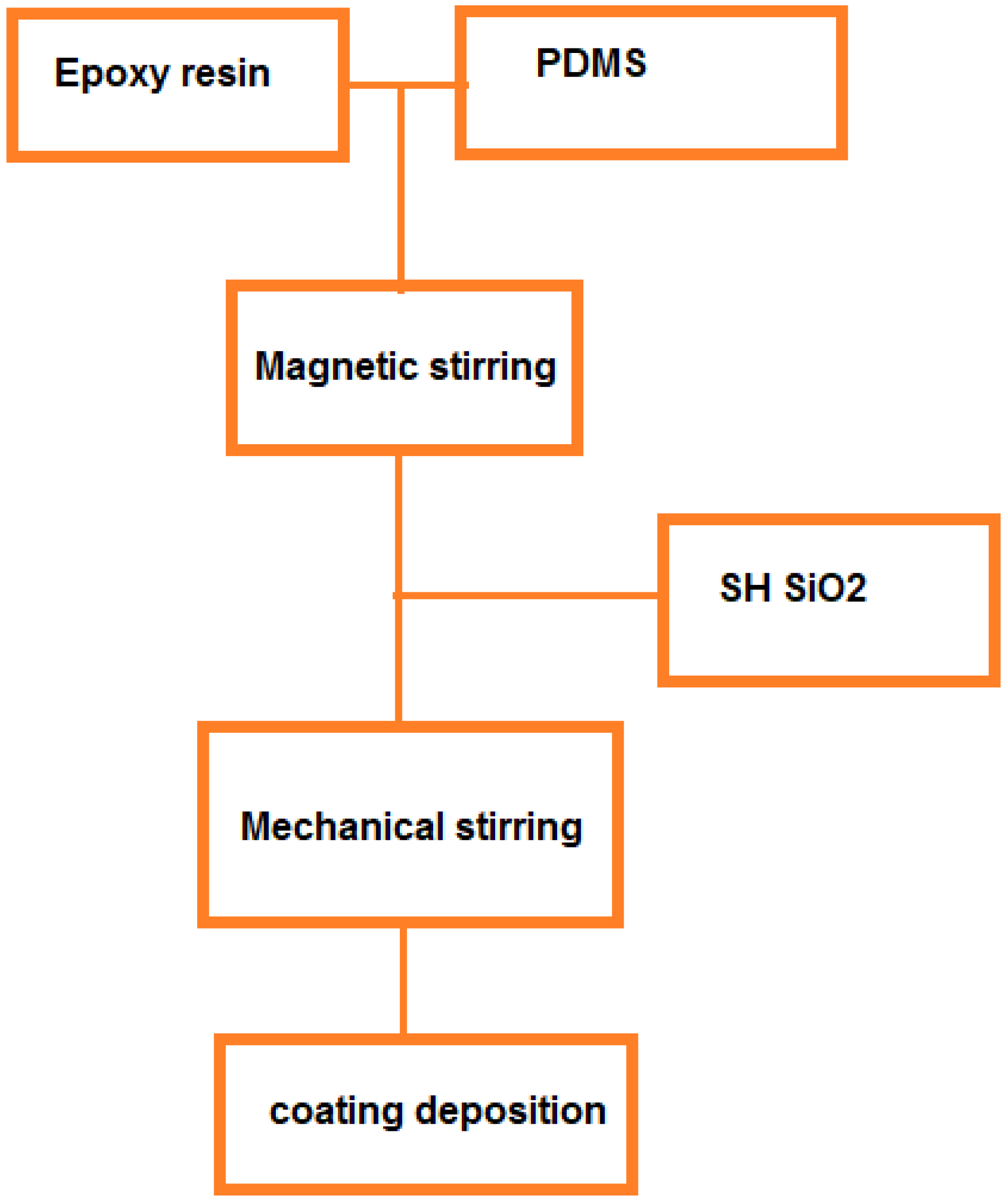
To prepare the nano-composite coating, epoxy resin was added to the solvent and stirred by using a mechanical stirrer for 20 min (Solution A). Also, some hexane was added to PDMS and stirred for 30 min (solution B). Then, the solution B was added to solution A and it was stirred for 30 min. A specific amount of the SH-SiO2 was added to the above solution and stirred by a mechanical stirrer for 30 min. finally, the obtained solution was sprayed (by a spray gun) on the surfaces of aluminum sheets and ACSR conductor, and it was placed in the environment to dry. The coating deposition process is shown in Figure 1.
Figure 1.
Coating deposition process steps.
2.4. Characterization
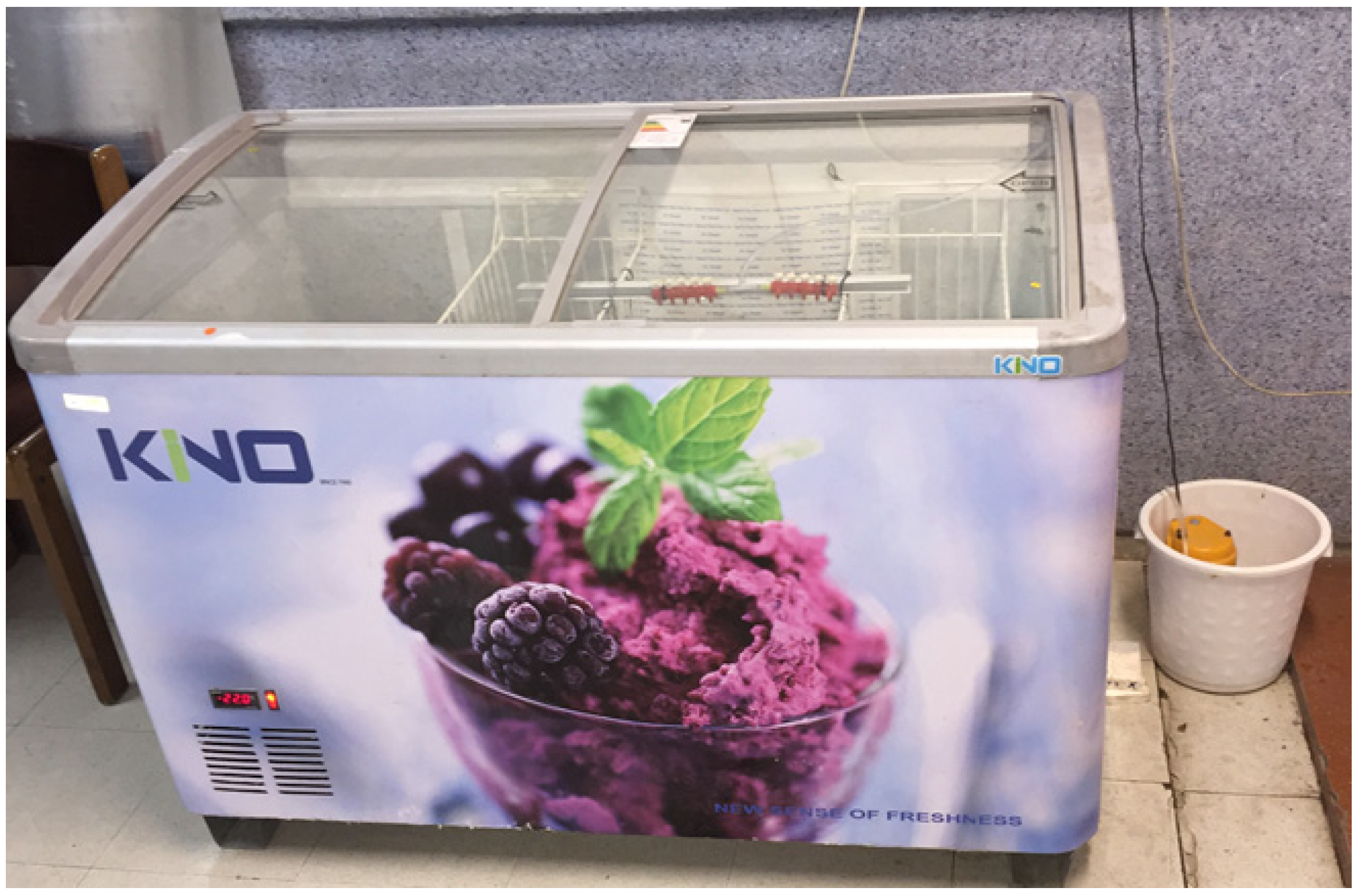
The crystal structure of the SH SiO2 was obtained using a Bruker X-ray diffractometer (XRD, D8ADVANCE, Germany, Ni-filter, Cu Kα radiation λ = 1.5406 °A). The surface morphology of the nanoparticles was observed using TEM electron microscopy (TEM, Philips EM208S 100KW). Attenuated Total Reflectance Fourier Transform Infrared (ATR-FTIR, Perkin Elmer Model Specuum400) was used to evaluate the surface functional groups on the film surface. Water contact angles (WCA) were measured using a video and photo-based contact angle measurement system (Dino-lite, AM-4515T8-Edge). The water contact angle was measured at least 3 times across the surface of the sample using a distilled water drop of 3 microliters. The water contact angle (±1 standard deviation) was measured at the ambient temperature of 30 ℃ and relative humidity of 50%. Iron oxide powder was also used for the self-cleaning test. The iron oxide powder was evenly sprayed on the surface. Then, water drop was applied to the surface by an injector needle tube at a distance of 1 cm and the surface was inclined gently (30°) to drop downwards. Photographs were taken before and after dropping to the surface. Comparison of the photos taken by the droplet motion and the effect of iron oxide powder in different samples were qualitatively compared. To perform the self-cleaning test, two uncoated and coated aluminum sheets were set as a ramp with an angle of about 30 degrees. On the surface of the samples, soil was sprinkled as a representative of pollution, and water droplets were dripped on the surface of the samples by a needle tube. Using a camera, the self-cleaning process was recorded. A refrigerator has been used to perform the artificial icing test (Figure 2). Super-cold water is used for the test, which is transported by a pump into the chamber through plastic hoses. The droplet spraying system was used to simulate the falling of the super-cold water drops on the conductor. The samples are placed inside the device in such a way that half of it with hydrophobic nano-coating and the other half without coating is exposed to super cold-water droplets. The starting temperature of the icing test was set at -14 °C. The icing test was performed for 80 min and the icing process was recorded using a camera.
Figure 2.
Artificial icing chamber.
3. Results and Discussion
Figure 3 shows the images of water droplets on the surfaces of modified silica nanoparticles. According to the Figure 3, it can be seen that the water droplets are placed on the surface in a completely spherical shape, and as a result, they show super-hydrophobic behavior.
Figure 3.
Water droplets Images on the surfaces of modified silica nanoparticles.
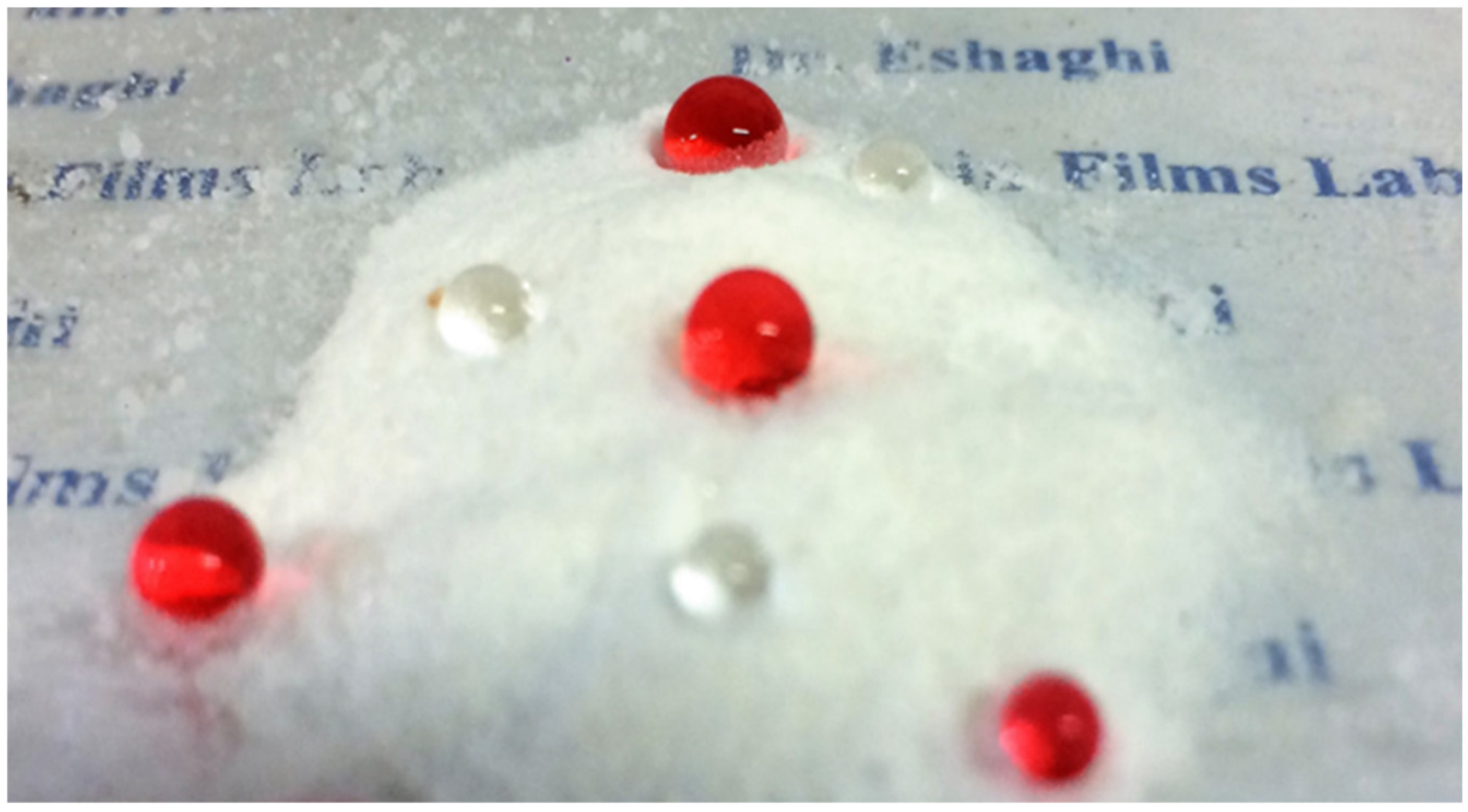
Figure 4 shows the X-ray diffraction pattern of the modified silica nanoparticles. As seen in Figure 4, the diffraction pattern shows a broad peak at θ2=22°, which indicates the amorphous nature of the modified silica nanoparticles [25].
Figure 4.
X-ray diffraction pattern of the hydrophobic silica nanoparticles.
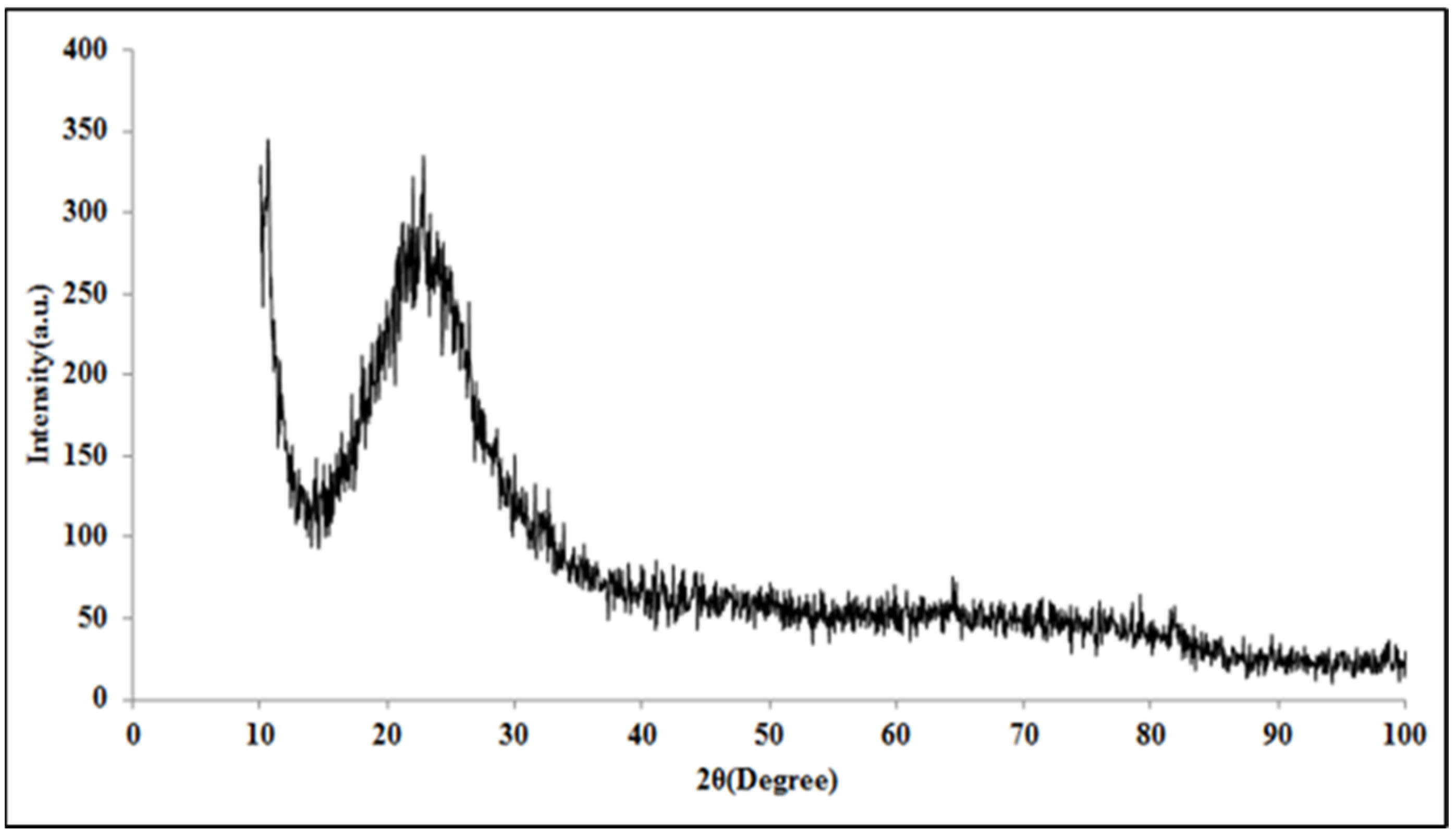
Figure 5 shows the ATR-FTIR spectrum of the modified silica nanoparticles. The absorption bands observed around the wavenumber of 12,900 cm−1 are due to the stretching vibration of –CH3 groups, and the absorption peaks at the wavenumber of 1780 cm−1 indicate the stretching vibration of Si-C and the kinetic vibration of –CH3. The absorption bands observed around 11,270 cm−1 are also caused by the symmetric and asymmetric deformation of –Si–CH3 bonds. A very strong absorption band near 1100 cm−1 is due to the stretching vibration of Si-O-Si bonds. Peaks around 1165 cm−1 and broad absorption band around 1340 cm−1 are due to OH- groups [25,26,27,28,29,30,31,32,33]. The presence of methyl groups due to decreasing of the surface energy causes the surface of silica to change from a hydrophilic to a hydrophobic state.
Figure 5.
ATR-FTIR results of the hydrophobic silica nanoparticles.
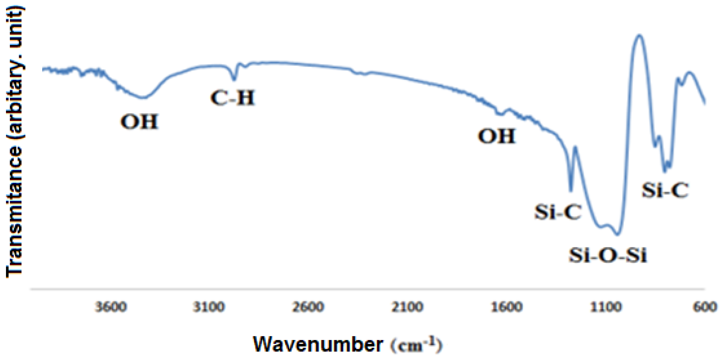
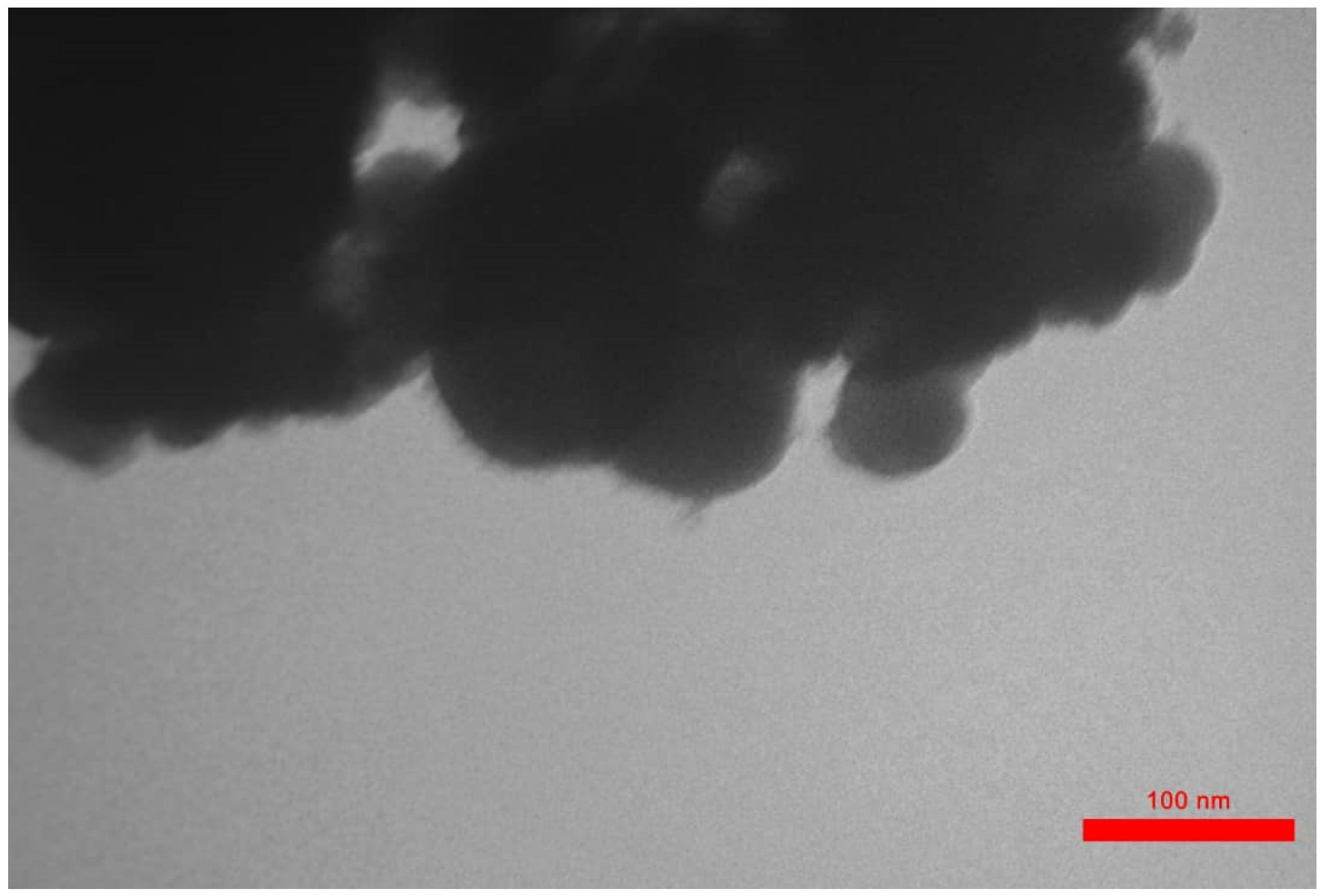
Figure 6 shows the TEM image of the modified silica nanoparticles. According to the figure, it can be seen that the average particle size is between 18 to 30 nm.
Figure 6.
TEM image of the synthesized silica nanoparticles.
The water droplets images on the surface of uncoated and coated aluminum substrates are shown in Figure 7. According to the figure, it can be seen that with the application of nano-coating, the contact angle of the aluminum substrate has increased from 64° to 141°.
Figure 7.
Images and contact angle of water droplets on (a) uncoated aluminum (b) and coated aluminum substrates.
Figure 7.
Images and contact angle of water droplets on (a) uncoated aluminum (b) and coated aluminum substrates.
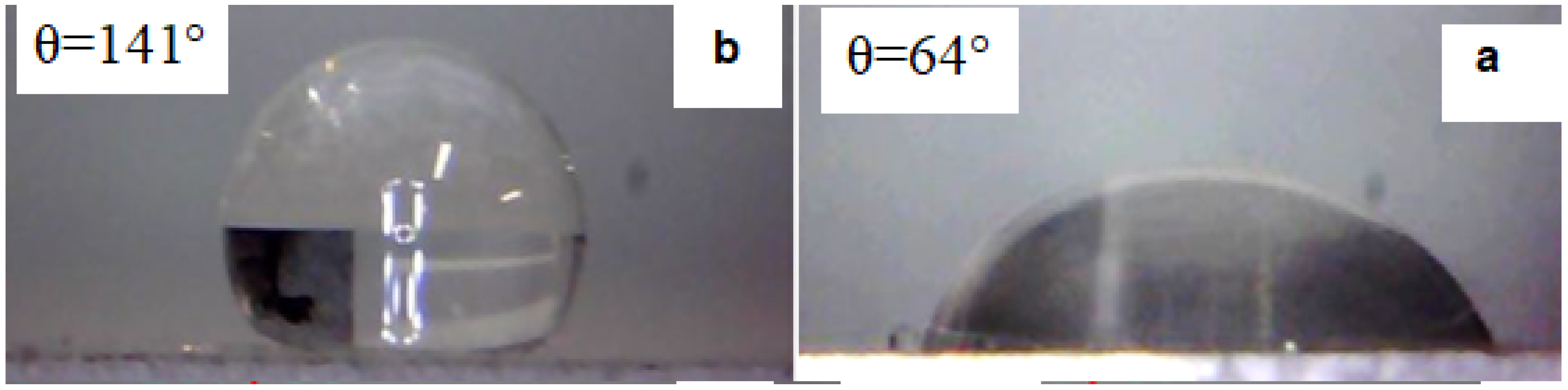
Figure 8 shows the images of water droplets on uncoated and coated conductors. As can be seen from Figure 8, the water droplets spread on the uncovered conductors and flow on its surface. On the other hand, the water drops are placed spherically on the surface of the coated conductor and are separated from the surface with the least vibration or increase in the weight of the drop. Therefore, when these droplets freeze, they will be easily separated from the conductor surfaces due to the low contact surface.
Figure 8.
Images of water droplets on (a) uncoated and (b) coated conductors.
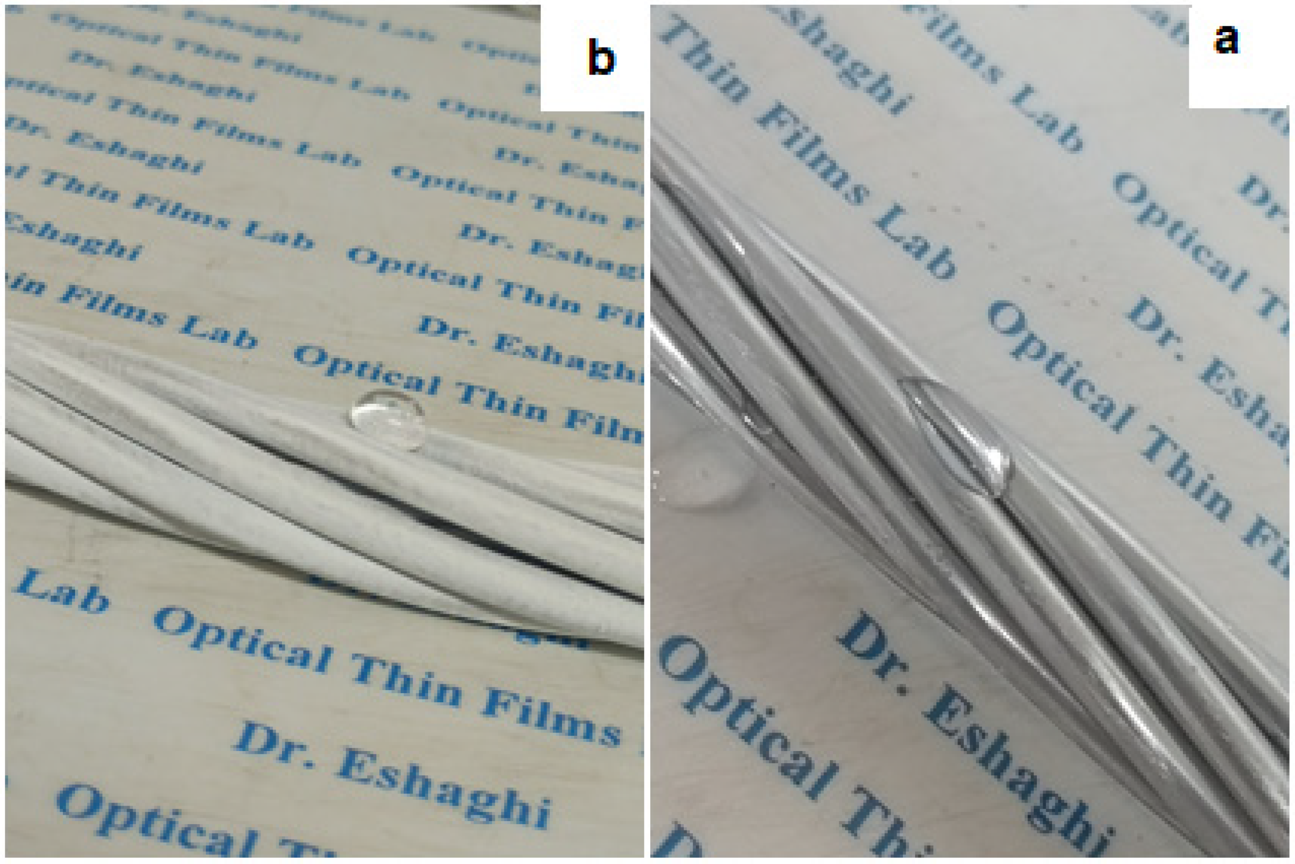
Figure 9 shows the self-cleaning behavior of the samples. According to the figure, it can be seen that in the uncoated sample, the water droplets were completely spread on the surface of the sample due to absorption by the soil particles and stopped moving. It was observed that the soil particles remained on the surface and due to the wetting of the surface by water droplets, they stuck to the surface of the sample and created a muddy state. On the opposite side, in the aluminum-coated sample, the water drops rolled on the surface of the sample and the soil particles stuck to the surface of the water drop and rolled down and were completely separated from the surface and then the surface showed self-cleaning behavior.
Figure 9.
Self-cleaning Images of the bare and coated aluminum substrate.
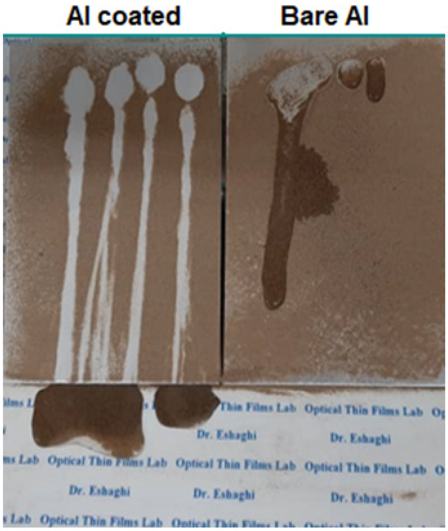
Figure 10 shows the icing test results of the samples at different times. The only left side of the sample is coated. According to the figure, it can be seen that the water droplets on the surface of the coated side of the conductor were frozen in a spherical shape and in this case, they have the lowest contact surface with the conductor. In this condition, ice drops are easily separated from the surface and create an anti-icing condition.
Icing occurred faster on uncoated surfaces and ice crystals formed under the conductor, while on the nanocoating surface, icing did not occur and ice formation occurred in the uncoated areas and at the edge of the conductor. After some time, due to the low contact surface of the ice cones with the surface of the coated conductor and the increase in the weight, the ice cones were easily separated from the surface. By increasing the icing time, the diameter of the icicle on the uncovered side increases, and in the coated area, small icicles are formed on the uncovered edge, which are thinner compared to the uncoated side. By increasing the spraying of super-cold-water droplets, the diameter, and height of the icicle increased in the uncoated sample, while the candelabra grew little on the coated side. Also, according to the figure, it can be seen that large icicles are formed on the interface between the surface with and without coating. These conditions are due to the escape of water droplets from the hydrophobic side and transfer to the uncoated side and result in the formation of large icicles.
Figure 10.
Icing images on the bare and coated conductors.

Therefore, by deposition of nano-coating, the rate of formation of icicles slows down compared to the uncoated sample, and the formation of large and thick icicles is prevented. Thus, the prepared nano-coating can be used to prevent the icing of conductors in the overhead power lines system.
4. Conclusions
In this study, epoxy-modified silica nano-composite coating was applied on the copper substrates. The results indicated that:
- The average particle size of the hydrophobic silica was measured as 18 to 30 nm.
- Epoxy-modified silica nano-composite coating increased the water contact angle of the aluminum substrate from 46° to 141°.
- The icing test results showed that hydrophobic coating increased icing time during ice formation on the conductors.
- Epoxy-modified silica nano-composite coating showed the self-cleaning effect.
So, it can be concluded that epoxy-modified silica nano-composite coating can be used as a self-cleaning and anti-icing coating for power transmission line applications.
References
- W. Henson, R. Stewart, B. Kochtubajda On the precipitation and related features of the 1998 Ice Storm in the Montréal area” Atmospheric Research 83 (2007) 36–54.
- Hyde M. M., James W. F. “Transmission Icing a Physical Risk with A Physical Hedge” Power Engineering Society General Meeting, IEEE Print ISBN: 1-4244-0493-2, 2006.
- https://www.hydro.mb.ca/outages/ice_on_power_lines.shtml Accesses on March 2017.
- Masoud F. “Atmospheric Icing of Power Networks” e-ISBN: 978-1-4020-8531-4_ Springer Science+Business Media B.V. 2008.
- Harold M. I, et al. “Wind Ice and Snow Load Impacts on Infrastructure and the Natural Environment” Proceedings - Int. Workshop Atmos. Icing Struct. Uppsala, 2015.
- http://www.inmr.com/impact-icing-transmission-lines/accessed on March 2017.
- Masoud F., et al. “Coatings for Protecting Overhead Power Network Equipment in Winter Conditions” ISBN: 978-2-85873-334-7 CIGRE Publication 2015.
- A. R. Solangi, “Icing Effects on Power Lines and Anti-icing and De-icing Methods,” no. June, 2018.
- C. Kaiser, P. Skinkis, and M. Olmstead, Protecting Pevines from Winter injury, no. March. 2008.
- S. G. Derouich, J. Pinson, A. Lamouri, P. Decorse, S. Bellynck, R. Herbaut, L.Royon, C. Mangeney, Micro-patterned anti-icing coatings with dual hydrophobic/hydrophilic properties. Mater. Chem. A, 6 (2018) 19353-19357. [CrossRef]
- L. Cao, A. K. Jones, V. K. Sikka, J. Wu, D. Gao, Anti-Icing Superhydrophobic Coatings, Langmuir 25 (2009) 12444–12448. [CrossRef]
- F. Wang, C. Li, Y. Lv, F. Lv, Y. Du, Ice accretion on superhydrophobic aluminum surfaces under lowtemperature conditions, Cold Regions Sci. Tech., 62 (2010) 29–33, 2010. [CrossRef]
- I. Gutman, M. Radojcic, L. Carlshem, Reducing Ice Accretion Using Superhydrophobic Coatings on Conductors & Insulators, INMR, 21(2013) 139-144.
- V.F. Petrenko, C. R. Sullivan, Methods and systems for removing ice from surfaces, U.S. Patentno. 6653698, 2003.
- M. Radojcic, K. Halsan, I. Gutman, A. Dernfalk, L. Carlshem, L. Wallin, Comparative testing of different anti-ice coatings for overhead line conductors with special focus on ice accretion, RIV and visual impact,IWAIS-2013, St. John’s, NL, Canada, 8-11 (2013) 13-18,2013.
- T. Kitamura, D. Tagami, H. Nakamura, Y. Asano, T. Saitoh, T. Katayama, Snow-melting Magnetic Material Wire, Fujikura Technical Review, 2003.
- S. Pan, N. Wang, D. Xiong, Y. Deng, and Y. Shi, Fabrication of superhydrophobic coating via spraying method and its applications in anti-icing and anti-corrosion, Appl. Surf. Sci., 389 (2016) 547–553. [CrossRef]
- M. Abdolahzadeh Saffar, A. Eshaghi, and M. R. Dehnavi, Fabrication of superhydrophobic, self-cleaning and anti-icing ZnO/PTFE-SiO2 nano-composite thin film, Mater. Chem. Phys., 259, (2021) 124085.
- M. Balordi, A. Cammi, G. Santucci de Magistris, and C. Chemelli, Role of micrometric roughness on anti-ice properties and durability of hierarchical super-hydrophobic aluminum surfaces, Surf. Coatings Technol., 374 (2019) 549–556. [CrossRef]
- V. H. Nguyen, B. D. Nguyen, H. T. Pham, S. S. Lam, D.-V. N Vo, M. Shokouhimehr, T. H. H. Vu, T.B, Nguyen, S. Y. Kim, Q. V. Le, Anti-icing performance on aluminum surfaces and proposed model for freezing time calculation, Sci. Rep., 11 (2021) 1–9. [CrossRef]
- M. Farzaneh and et al., Coatings for Protecting Overhead Network Equipmen Power in Winter Conditions, Ownership of a CIGRE publication, 2015.
- L. Gutman, J. Ludengerard, V.Naidoo, B. Adum, Technologies to reduce and remove ice from phase conductors and shield wires: applicability for Norwegian conditions, IWAIS, 2019.
- R. Bernardo, R. Catalão, and L. Ilharco, ANTI-ICE AND SNOW COATING FOR EDP DISTRIBUIÇÃO’S OVERHEAD LINES, 24th International Conference on Electricity Distribution Paper 0279, Cired (2017) 12–15.
- Y. Wu, X. Li, C. Mi, L. Zong, and X. Wang, Preparation and characterization of perfluorine-SiO2 nanoparticles and superhydrophobic fluorosilicone/silica hybrid composite coating, Appl. Phys. A Mater. Sci. Process., 125 (2019) 826.
- G. Cognetti, F. Maltagliati, C. Pretti, Antifouling coatings and ecological control in marinas, Mar. Pollut. Bull. 64 (2012) 175–176. [CrossRef]
- A. Silkina, A. Bazes, J. L Mouget, N. Bourgougnon, Comparative efficiency of macroalgal extracts and booster biocides as antifouling agents to control growth of three diatom species. Mar. Pollut. Bull. 64 (2012) 2039–2046. [CrossRef]
- J. A. Lewis, Marine biofouling and its prevention on underwater surfaces. Mater Sci Forum. 22 (1998) 41–61.
- A. Abbott, P.D. Abel, D.W Arnold, A.Milne, Cost-benefit analysis of the use of TBT: the case for a treatment approach. Sci. Total Environ. 258 (2000) 5–19. [CrossRef]
- L.D. Chambers, K.R. Stokes, Walsh, F.C., Wood, R.J.K., Modern approaches to marine antifouling coatings. Surf. Coat. Technol. 201 (2006) 3642–3652. [CrossRef]
- P. Szewczyk, The role of nanotechnology in improving marine antifouling coatings. Scientific Journals Zeszyty Naukowe Maritime University of Szczecin, 24 (2010) 118–123.
- G. Nallathambi, T. Ramachandran, V. Rajendran, R. Palanivelu, Effect of silica nanoparticles and BTCA on physical properties of cotton fabrics, Mater. Res. 14.4 (2011) 552-559. [CrossRef]
- M. Borzou Esfahani, A. Eshaghi, S. R. Bakhshi, Transparent hydrophobic, self-cleaning, anti-icing and anti-dust nano-structured silica based thin film on cover glass solar cell, J. Non. Cryst. Solids. 583 (2022) 121479. [CrossRef]
- H. Salehi, A. Eshaghi, M. Rezazadeh, H. Zabolian, Antireflective and anti-dust modified silica based thin film on solar cell cover glass, J. Alloys Compd. 892 (2022) 162228. [CrossRef]
Disclaimer/Publisher’s Note: The statements, opinions and data contained in all publications are solely those of the individual author(s) and contributor(s) and not of MDPI and/or the editor(s). MDPI and/or the editor(s) disclaim responsibility for any injury to people or property resulting from any ideas, methods, instructions or products referred to in the content. |
© 2023 by the authors. Licensee MDPI, Basel, Switzerland. This article is an open access article distributed under the terms and conditions of the Creative Commons Attribution (CC BY) license (http://creativecommons.org/licenses/by/4.0/).
Copyright: This open access article is published under a Creative Commons CC BY 4.0 license, which permit the free download, distribution, and reuse, provided that the author and preprint are cited in any reuse.


