1. Introduction
Large logistics buildings must be quickly constructed to recover their investment costs. Thus, it is crucial to consider the economic advantages of early operation and to reduce construction management costs (labor, equipment, and other expenses) [
1,
2]. Precast concrete (PC) structures are considered particularly beneficial over reinforced concrete (RC) structures in terms of construction time [
3,
4,
5,
6,
7]. Furthermore, given that large logistic buildings have high floor heights and long spans, columns and beams in the range of 5–10 m must be installed [
8]. However, construction requires a considerable amount of temporary work [9-12]. Accordingly, the capital-intensive PC technique is beneficial because equipment and material costs are decreasing and labor costs are increasing [13-15]. The PC method is preferred because of the shortening of the construction [
3,
4,
5,
13], quality assurance [
14,
15], and cost-savings [15-17], and it has been extensively researched [
18,
19].
A large crane is required to lift heavy PC members, and PC members are installed inside the crane working radius following a review of crane specifications and designs [
20,
21]. Mobile cranes are the most commonly utilized and shared resources among on-site resources with considerable mobility and weight, and they are involved in all types of lifting operations [22-24]. Prior to commencing work, a thorough lifting plan should be devised, especially given the complexities of lifting heavy objects [
25,
26]. Lifting for PC construction is conventionally performed in accordance with a production schedule based on the field manager experience. Furthermore, issues, such as procurement delays in factory production at the site and reproduction due to inaccurate PC member details, often lead to delivery delays for PC members [
27].
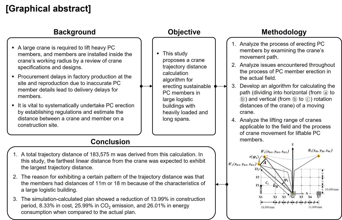
When simulation techniques are expanded, it is vital to systematically undertake PC erection by establishing regulations and estimate the distance between a crane and member on a construction site. Hence, a distance calculation method that simply and rapidly calculates the trajectory distance based on the crane position must be devised to select a plan that minimizes crane work among erection plans. Therefore, the objective of this study is to develop a crane trajectory distance calculation algorithm for erecting sustainable PC members in large logistic buildings with heavily loaded and long spans. Cranes utilized on construction sites are classified as fixed cranes or mobile cranes based on the weight of materials. The three types of mobile cranes are hydraulic truck, crawler, and tower cranes. The scope of this study is confined to crawler cranes, which are mostly utilized for PC erection of large logistic buildings with heavy loads and long spans.
This study is conducted based on the following steps.
- 1)
Investigate potential methods for PC member erection and select a method that is suited to the field.
- 2)
Analyze the process of erecting PC members by examining the crane movement path.
- 3)
Analyze issues encountered throughout the process of PC member erection in the actual field.
- 4)
Develop an algorithm for calculating the path of a moving crane.
- 5)
Analyze the lifting range of cranes applicable to the field and the process of crane movement for liftable PC members.
- 6)
Calculate the trajectory distance using simulation.
- 7)
Compare and assess the cost, construction time, CO2 emissions, and energy consumption of the actual plan and simulation-calculated plan.
2. Preliminary Studies
2.1. Literature review
Numerous algorithms and methods have been developed to automate the crane work planning process for improving the productivity and efficiency of crane operations [
28]. Some of the crane-related research topics include optimizing crane and feed positions [29-31], crane type selection [32-34], lift sequence simulation [35-38], three-dimensional (3D) visualization of crane work to detect potential collisions [
23,
34,
39], and crane lift path planning [40-44].
These studies can be divided into three categories: 1) Optimizing the crane location and material supply location according to the selected crane type, 2) The crane load, and the distance between the crane boom and the structure, and 3) The crane movement path.
First, research on optimizing the crane location and material supply location according to the selected crane type was reviewed. To optimize crane and material location, several studies have determined the appropriate crane type based on a variety of project factors [30,32-34]. These factors included the required operating clearance, construction height, soil foundation, duration, and site accessibility. Furthermore, in a recent study, the effect of wind was examined on the crane body as an additional factor when selecting the crane type [
45]. The crane and material delivery locations can be optimized according to the type of crane selected. A genetic-algorithm-based model was developed to investigate the optimal feeding position of a tower crane in which the hook travel time was considered [
29]. A more complex method for optimizing the tower crane set position and feed position for high-rise buildings has also been proposed using mixed-integer linear programming [
46].
The crane load, and the distance between the crane boom and the structure was reviewed. Al-Hussein et al. [
47] suggested a technique for selecting a workable crane based on independent 2D designs by evaluating whether the crane load and distance between the crane and building component match the basic requirements. The optimal crane was selected based on several constraints, including the minimum clearance with the building, crane operating radius, and crane load. Hasan et al. [
48] computed the crane leg pressure at various horizontal swing angles and ensured safety by monitoring leg pressure during crane operation. Moselhi et al. [
49] developed a mobile crane selection and positioning system to establish a 3D model based on the coordinates and sizes of hoists and obstacles. The system selects the optimal crane by simulating the position and probable collisions of the mobile cranes in a virtual environment. Based on previous studies, they suggested a systematic method for selecting a mobile crane.
Third, in the research on the crane movement path, Lei et al. [
43] proposed a general method for verifying a mobile crane lifting binary (yes/no) path. They considered site constraints by calculating the minimum and maximum crane lift radii based on capacity and crane configuration. Reddy and Varghese [
50] developed a tool that identifies a lift pathway that satisfies planning requirements by applying two heuristic searches. Chang et al. [
51] developed a method for automatically and efficiently planning an installation path using a crane. The two proposed methods composed the crane installation space by including the crane load capacity and environmental obstacles and obtained a collision-free path in the constructed space using the probabilistic road map (PRM) method. Therefore, various studies have been conducted to increase the productivity and efficiency of crane work. However, there is no research to systematically perform the erection of PC members by calculating the trajectory distance by selecting a PC construction case site. In other words, research on arranging a crawler crane to calculate the trajectory distance of a crane boom and to plan a path has not been conducted.
2.2. PC members erection analysis
2.2.1. PC members erection method using crane
The crane position was determined by the working radius because the PC members were installed within the working radius of the crane. Given that the crane is moved after all members within the working radius are installed, the position of the crane is determined by the erection plane. In general, there are three types of PC member erection. Floor-by-floor erection is a method of installing PC members on the next floor after installing all PC columns, girders, and slabs on each floor. There are no problems with the structural stability of the building because joint concrete is poured on each floor [
52]. Most pin-joint PC frames are erected in this manner [
53]. Second, cascading erection is a method for stacking PC members in a stepwise manner within the range of the crane boom. This is applied when the construction time for each floor is insufficient [
54]. Third, section-by-section erection is easier than other erection methods for securing the efficiency of equipment operation and workspace by constructing PC members in a specific section on all floors [
55,
56]. In this study, the cascading erection, as shown in
Figure 1, is adopted to reduce the construction time.
2.2.2. PC members erection process using crane
The crane moving path can be defined in two ways: (i) movement of the crane boom when lifting a member and (ii) movement of the position through the horizontal movement of the crane.
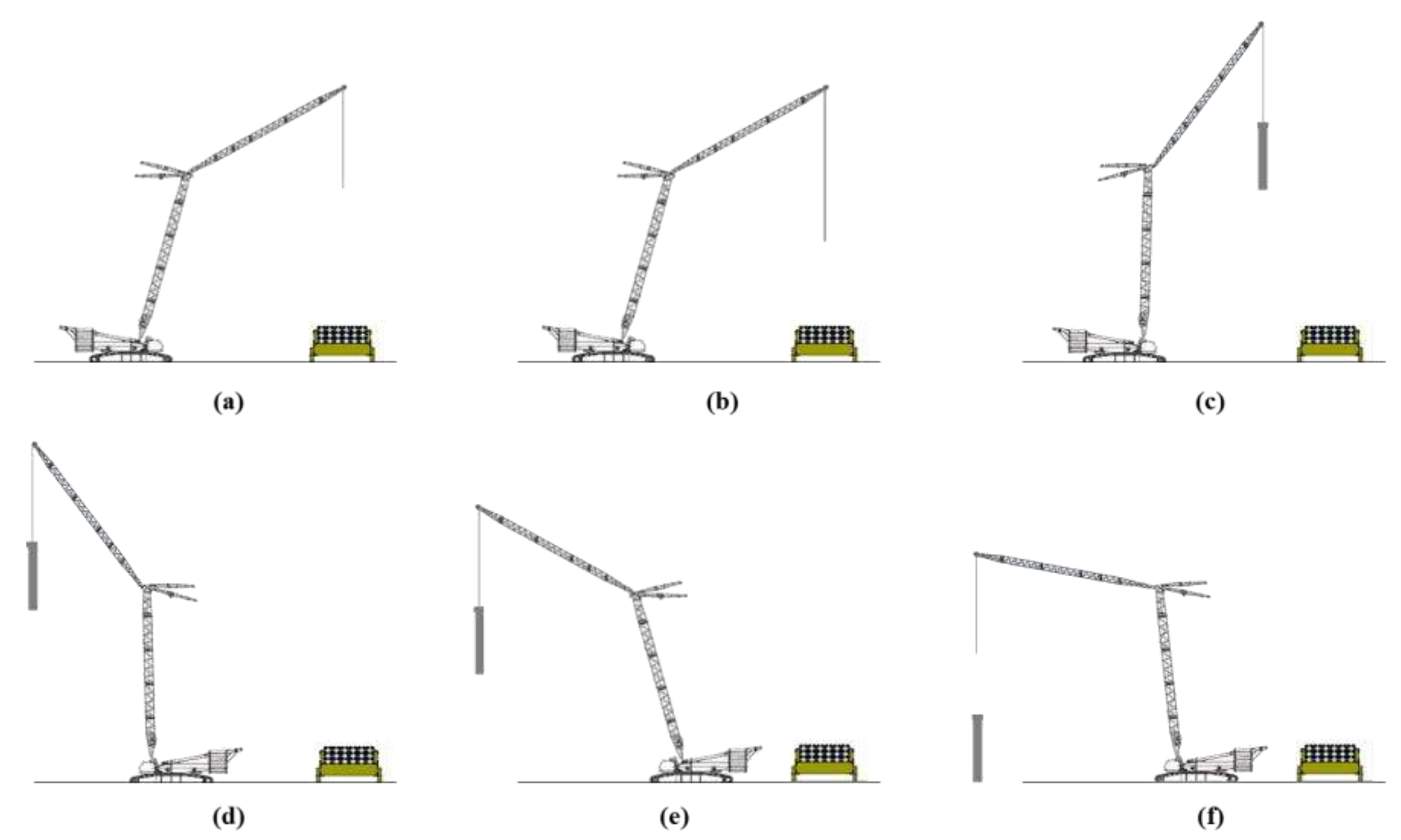
Figure 2 shows the boom movement of a crane when lifting a member. To erect a PC member using a crane, the member to be erected on the trailer is fixed by lowering the wire (
Figure 2b) after determining the location of the trailer and crane (
Figure 2a). The PC members (
Figure 2c) are lifted up and rotated to the member erection position (
Figure 2d). The members are then lifted down to the member erection direction (
Figure 2e) and pulled down to the member erection position, and the erection is completed (
Figure 2f). The movement of the crane boom can be divided into horizontal and vertical movements. In this study, the rotational movement (
Figure 2d) is defined as a horizontal rotational movement based on the head of the crane boom, and the up-and-down movement (
Figure 2c and 2e) is defined as a vertical movement.
3. Actual erection case analysis
3.1. Site condition review
The case project is conducted on four floors above the ground. The second to fourth floors are PC structures, the core is a reinforced concrete structure, and the roof is a steel frame structure. Thus, the bottom floors of the second through fourth floors of the PC structure are targeted. The site conditions must be analyzed to efficiently erect PC members.
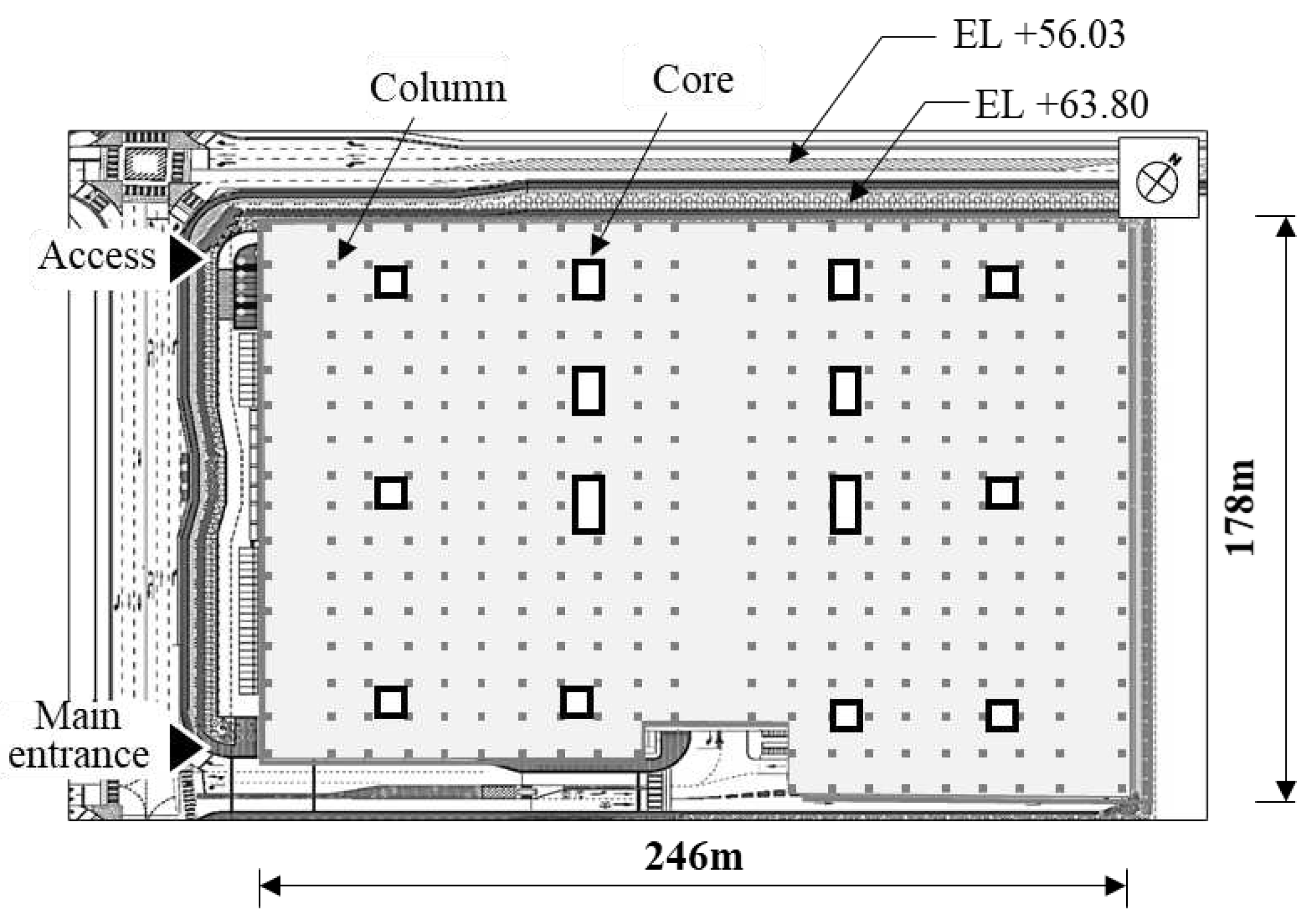
Figure 3 shows the 2nd-floor plan of the case site and an overview of the site conditions. When erecting PC members, the movement line of the mobile crane and PC member-carrying line are important. The northeast and southeast sides of the site are adjacent to other sites, and the northwest site and access road are +63.80 m and +56.03 m in elevation (EL), respectively, with a difference of 7.8 m. Therefore, entry into the site is impossible. Moreover, the main entrance can be positioned on the southernmost side on the southwest side of the site, ruling out the vehicle access limit section.
Figure 1.
Site condition analysis.
Figure 1.
Site condition analysis.
Additionally, the PC members of the site are analyzed to simulate their erection. In this study, PC columns and PC beams are targeted, whereas PC slabs are excluded. As a result of aggregation based on the member list of the case site, 1,004 columns and 1,284 beams are obtained. When the dimensions of PC columns and beams are analyzed, the PC columns are 0.8–1.7 m wide, 0.8–1.0 m high, 9.2 m long, and 5.9–15.6 m3 in volume, whereas the PC beams are 0.5–1.3 m wide, 1.0–2.6 m high, 11.0–23.0 m long, and 11.0–34.8 m3 in volume. If the unit weight of reinforced concrete is 2.4 ton/m3, then the weight is 14.2–37.4 t for the column and 26.4–83.6 t for the beam.
3.2. Crane path analysis of the case project
Erection was performed according to the plan of the actual site.
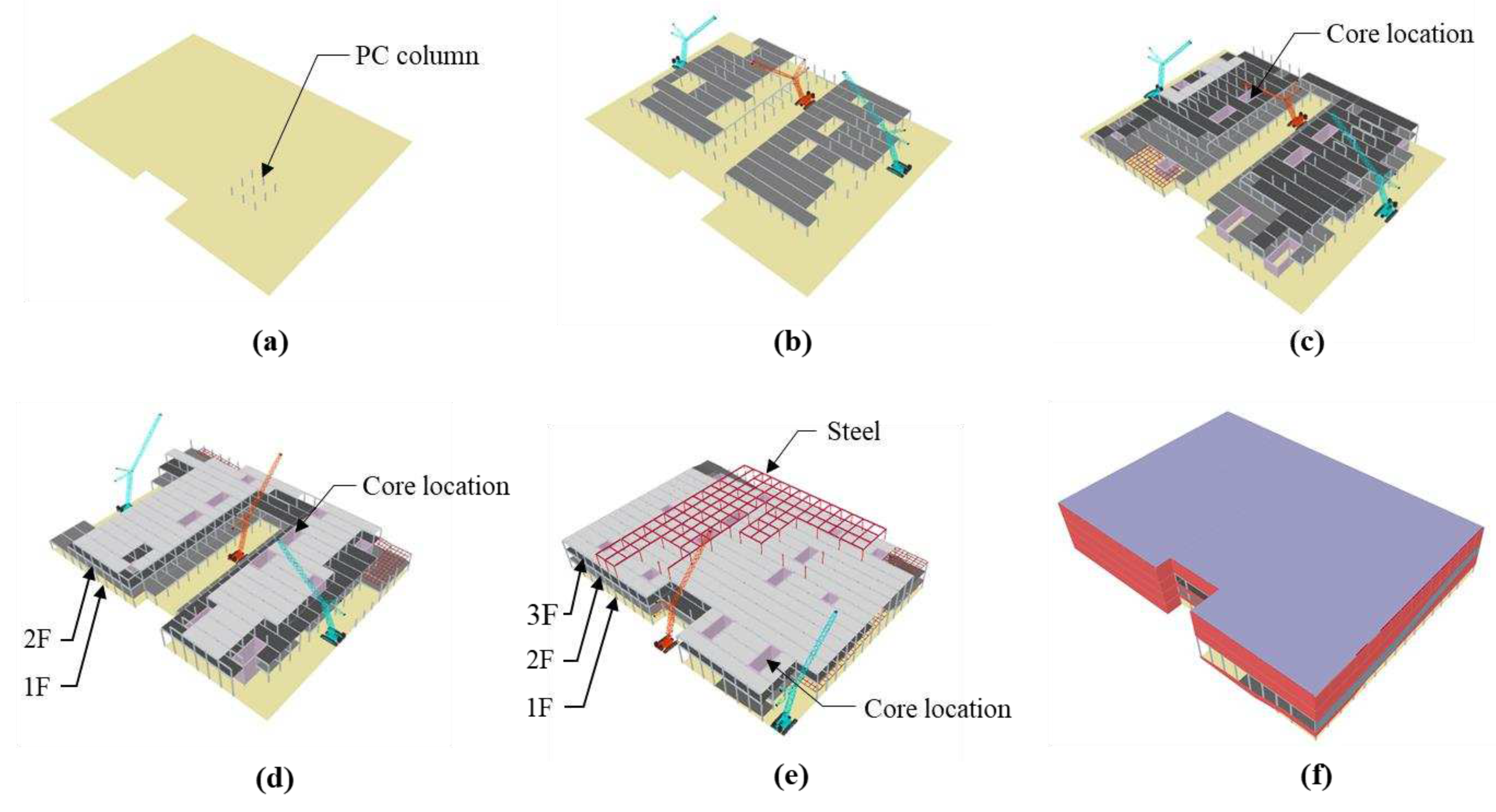
Figure 4 shows the monthly processes. As shown in
Figure 4(a), the PC column member on the east side is erected on the first day of construction. Subsequently, as shown in
Figure 4(b) and (c), the PC members of the first and second floors are sequentially erected by prioritizing the construction of each floor. Three cranes erected PC columns on the first floor and some girders and slabs on the second floor. The core, which is an RC structure, was combined with PC columns and beams for joining. This implies that the core was constructed according to the erection plan for the PC columns and beams. As shown in
Figure 4(d), cascade installation is applied, and it took 172 calendar days to erect all PC components (Lee et al., 2020).
Figure 4(e) and (f) show the working conditions after eight and ten months, respectively. As shown in these Figs, the PC and RC core erection is completed on all floors, and the steel frame is erected and finished on the 4th floor. Thus, PC members were erected without any specific rules in the actual field. This is due to the fact that the PC members were procured by reflecting the production schedule available at the factory during PC member erection planning.
Figure 2.
Actual erection process of case project: (a) D+1, (b) D+35, (c) D+70, (d) D+105, (e) D+140, (f) D+172.
Figure 2.
Actual erection process of case project: (a) D+1, (b) D+35, (c) D+70, (d) D+105, (e) D+140, (f) D+172.
4. Algorithm for crane moving path calculation for sustainable erections of PC members
Before erecting the PC members, the operator is not required to reposition the mobile crane [
57], thereby reducing space collisions between the crane and building via a crane moving plan. Crane movement planning requires a number of complex decisions while adhering to a wide range of criteria and constraints. Thus, these decisions are usually time-consuming and largely dependent on experience. However, currently, given that the fourth industrial revolution has commenced and construction sites are increasingly robotized, a PC member erection plan should be systematically established by setting rules and calculating the distance between the crane and members.
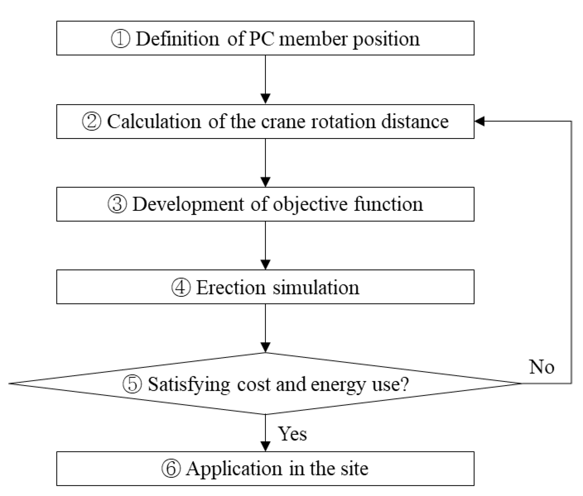
Figure 5 shows the algorithm for calculating the crane-moving path.
Figure 3.
Algorithm for crane-moving path calculation.
Figure 3.
Algorithm for crane-moving path calculation.
1) Definition of PC member position
Using the floor-by-floor method at the case site is difficult when a PC is used. Given that PC erection is conducted inside the building at the case site, a crane can only be erected at a distance. Therefore, PC erection was performed in a cascaded manner. If the building is not large, PC members can be produced on-site at a specified location within the crane rotation radius. However, if the building is large, as in the case of this study, it should be produced in a place where erection can be easily performed. For a large-scale PC structure with a large floor area, a construction plan should be prepared in line with a safe workflow that considers crane productivity. As shown in
Figure 6(a), PC erection was planned with three 550-t mobile cranes at the case site. Consequently, it is necessary to prepare a plan to enable erection within the working radii of these cranes. For each 550-t crane, a working radius of up to 74 m can be used by applying a 54-m jib and 36-m boom. Each zone (A–C) is divided into three areas. A zoning plan was established with the areas distributed considering the construction efficiency. The crane moved by erecting the members from the top to the bottom in each zone. Sample ⓐ is selected for crane A in
Figure 6(a), while the positions of the PC column, crane, and trailer on the first floor are defined in
Figure 6(b). With the position coordinates of the crane defined as (0,0,0), the position coordinates of each PC column can be defined as listed in
Table 1. The position coordinates of the trailer are defined as (0, −33, 0).
Figure 4.
Crane location plan: (a) Crane path, (b) PC member position definition on the sample ⓐ.
Figure 4.
Crane location plan: (a) Crane path, (b) PC member position definition on the sample ⓐ.
2) Calculation of the crane rotation distance
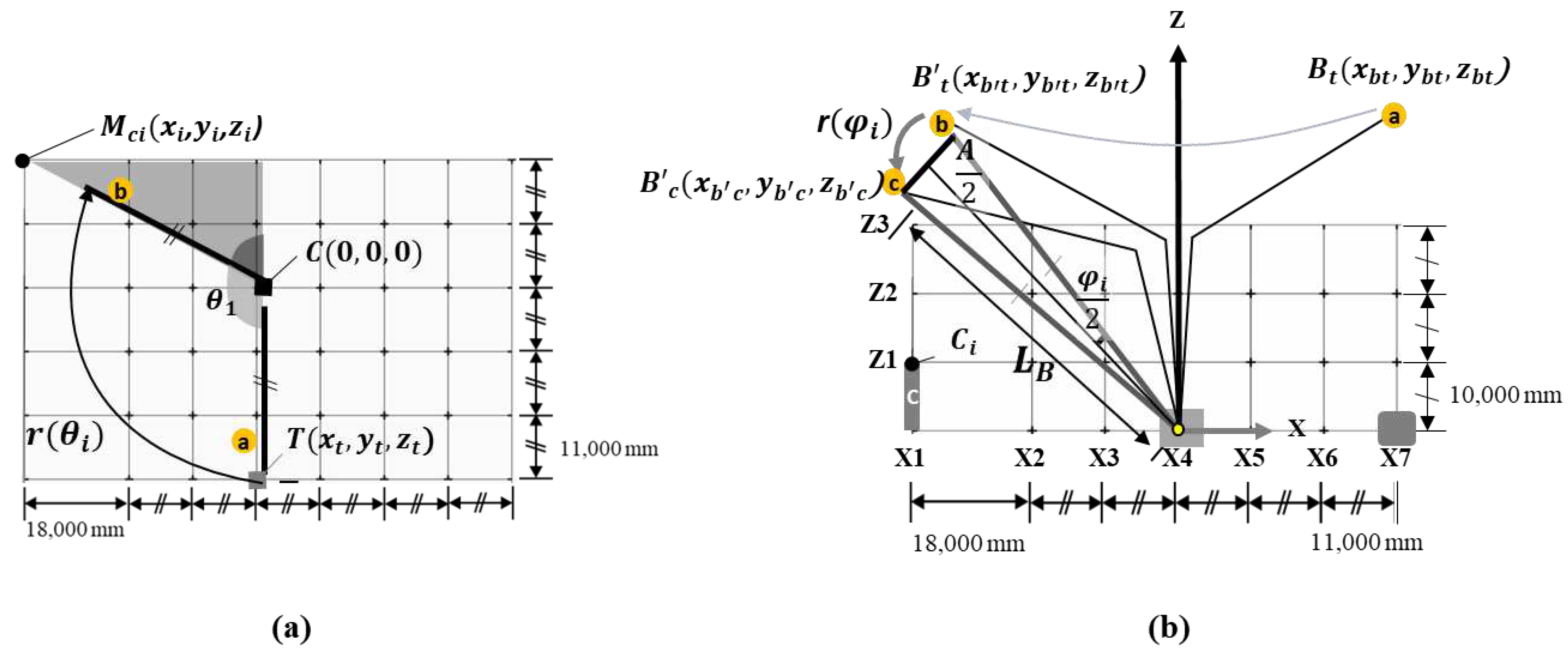
The crane rotation distance can be divided into horizontal (
Figure 7a) and vertical (
Figure 7b) rotation distances of the crane, and they are determined by calculating each distance and adding them. Hence, the horizontal rotation of the crane indicates movement from ⓐ to ⓑ in
Figure 7a, and the vertical rotation of the crane indicates movement from ⓑ to ⓒ in
Figure 7b. To calculate the horizontal rotation distance, the crane position coordinates are defined as (0,0,0), position coordinates of the column member as (xci, yci, zci), position coordinates of the trailer as (xt, yt, zt), and horizontal rotation distance as r(θi) as shown in Equation (1). The horizontal rotation angle of the boom is calculated using Equation (2) with relative coordinate values of the erected member whose origin corresponds to the position coordinate of the crane. Hence, the horizontal rotation angle can be calculated using the distance between the crane and erected member. The crane horizontal distance can be calculated using the distance from the crane to the trailer and the horizontal rotation angle of the boom as shown in Equation (3).
Figure 5.
Calculation of the crane horizontal and vertical rotation distances (in the order of 1, 2, and 3): (a) Crane horizontal rotation distances, (b) Crane vertical rotation distances.
Figure 5.
Calculation of the crane horizontal and vertical rotation distances (in the order of 1, 2, and 3): (a) Crane horizontal rotation distances, (b) Crane vertical rotation distances.
|
= column member position coordinates |
|
= x-coordinate of the erected column member |
|
= y-coordinate of the erected column member |
|
= z-coordinate of the erected column member |
| C |
= crane position coordinates |
| T |
= trailer position coordinate |
|
= x-coordinate of the trailer |
|
= y-coordinate of the trailer |
|
= z-coordinate of the trailer |
|
= horizontal rotation angle(rad) |
| r( |
= horizontal rotation distance |
|
= distance from crane to trailer |
|
= number of ith erected members at the crane position (1, …, n) |
Using Equations (1)-(3), the horizontal rotation angle of the boom is calculated, and the horizontal rotation distance of the crane is derived. The horizontal distances of n-members can be sequentially calculated. The algorithm steps are shown in the Algorithm 1.
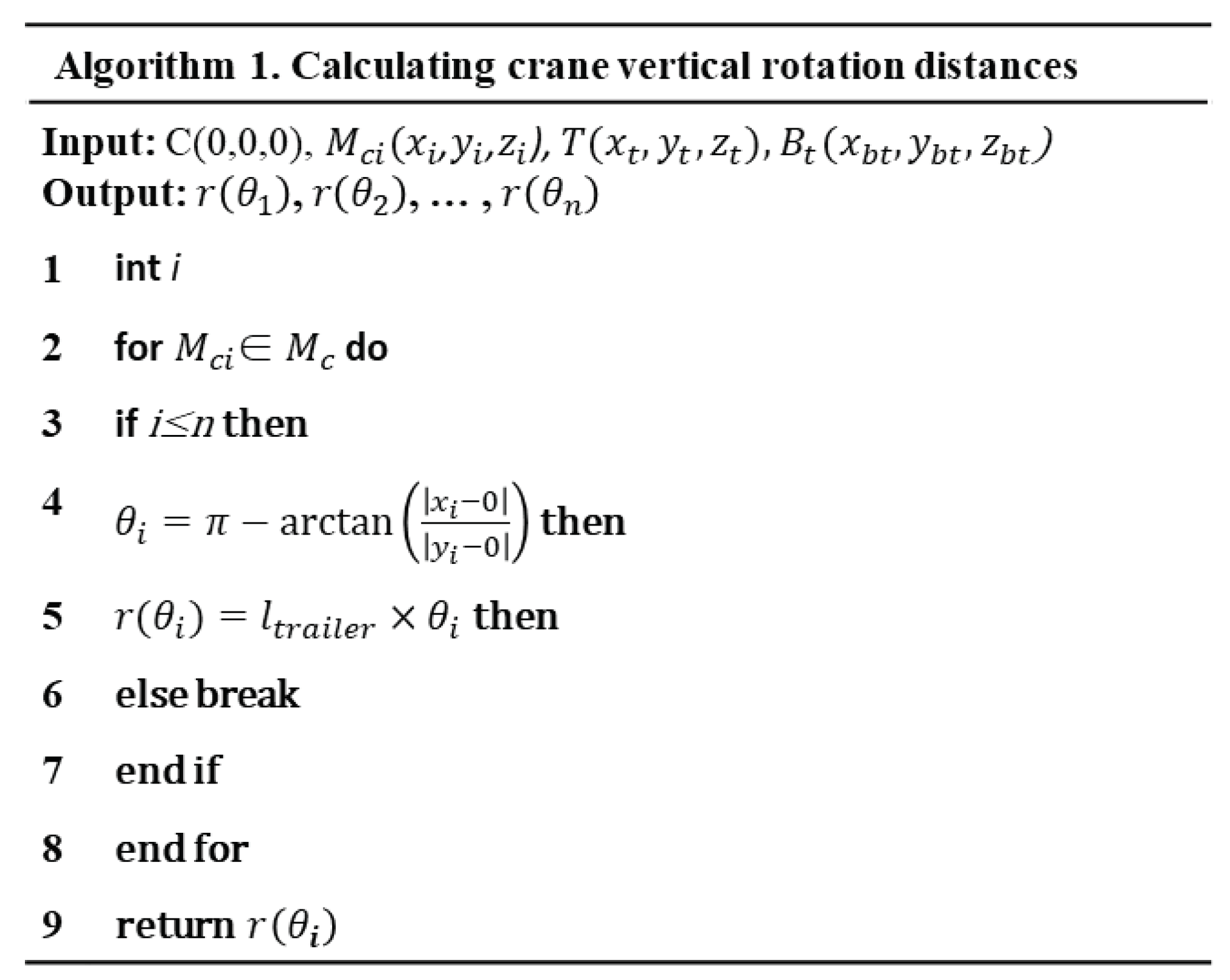
The head position of the boom must be defined to calculate the horizontal rotational distance. As shown in Equation (4), the position of the boom head is defined as (xbt, ybt, zbt), position of the horizontally rotated boom is defined as (xb't, yb't, zb't), position of the vertically rotated boom is defined as (xb'c, yb'c, zb'c), and the vertical rotation distance is defined as r(ψi). Furthermore, the linear distance during vertical rotation is defined as A and the boom length is defined as LB. As in Equation (5), the x- and y-coordinates of the trailer and boom are the same, while the x- and y-coordinates of the column member and horizontally rotated boom are the same. Therefore, the boom length during horizontal and vertical rotation is constant, and the horizontal distance from the crane to the boom head is also constant.
|
= boom head position coordinates |
|
= boom head x-coordinate |
|
= boom head y-coordinate |
|
= boom head z-coordinat |
|
= position coordinates of the horizontally rotated boom |
|
= x-coordinate of the horizontally rotated boom |
|
= y-coordinate of the horizontally rotated boom |
|
= z-coordinate of the horizontally rotated boom |
|
= position coordinates of the vertically rotated boom |
|
= x-coordinate of the vertically rotated boom |
|
= y-coordinate of the vertically rotated boom |
|
= z-coordinate of the vertically rotated Boom |
|
= x-coordinate of the trailer |
|
= y-coordinate of the trailer |
|
= x-coordinate of the erected column member |
|
= y-coordinate of the erected column member |
|
= number of ith erected members at the crane position (1, …, n) |
The distance from the crane to the erected member can be calculated using the x- and y-coordinates of the erected member as shown in Equation (6). According to the Pythagorean theorem, the z-coordinate of the vertically rotated boom can be calculated using the boom length and horizontal distance to the boom head as shown in Equation (7). Moreover, the linear distance during vertical rotation can be calculated using the z-coordinate of the boom and distance from the crane to the erected member as shown in Equation (8). The vertical rotation angle of the boom is calculated using Equation (9), with the boom length and linear distance during vertical rotation. The crane vertical distance can be calculated, as shown in Equation (10), using the boom length and vertical rotation angle. Finally, the boom trajectory distance
can be calculated by the sum of the horizontal and vertical rotation distances as shown in Equation (11).
|
= distance from crane to erected member |
|
= x-coordinate of the erected column member |
|
= y-coordinate of the erected column member |
|
= z-coordinate of the vertically rotated boom |
|
= boom length |
|
= y-coordinate of the boom head |
| A |
= linear distance during vertical rotation |
|
= y-coordinate of the horizontally rotated boom |
|
= z-coordinate of the horizontally rotated boom |
|
= z-coordinate of the vertically rotated boom |
|
= vertical rotation angle of the boom (radian |
| r( |
= vertical rotation distance |
|
= boom trajectory distance |
|
= number of ith erected members at the crane position (1, …, n) |
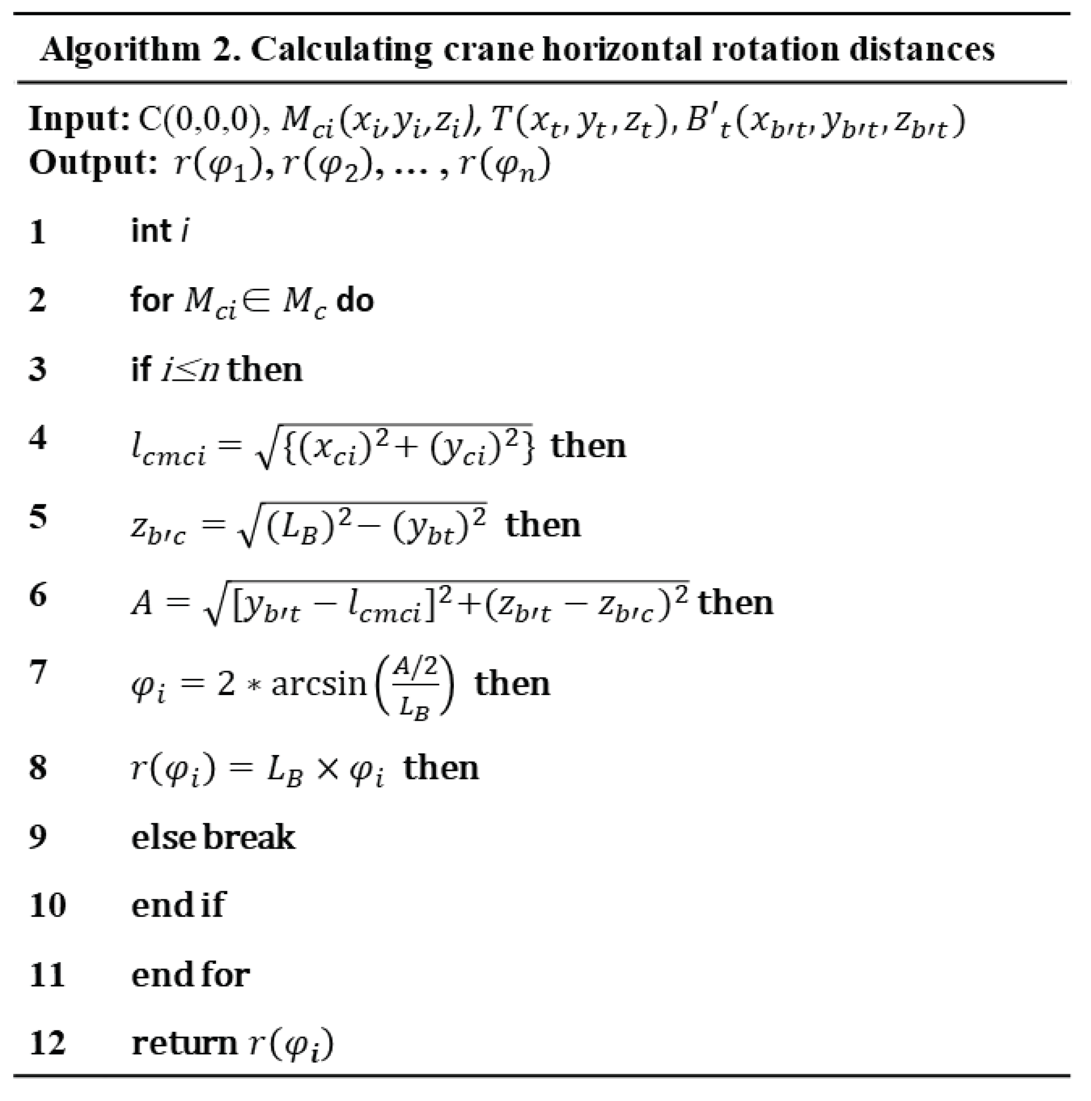
Using Equation (6)-(10), the distance from the crane to the installation member, and the z-coordinate of the vertically rotated boom are calculated. Then, the vertical rotation angle of the boom is calculated, and the vertical rotation distance of the crane is derived. The vertical distances of n-members can be sequentially calculated. The algorithm steps are shown in the Algorithm 2.
3) Development of the objective function
PC members are erected in descending order of the linear distance from the crane to the member. Thus, the member with the largest distance was selected from among the currently non-erected members. Based on this, a pathfinding-based moving path optimization algorithm was developed.
|
= total function equation of the linear distance from the crane to the erected member |
|
= total linear distance from the crane to the erected member |
|
= -coordinate of the erected member |
|
= -coordinate of the erected member |
|
= -coordinate of the erected member |
|
= -coordinate of the crane |
|
= -coordinate of the crane |
|
= -coordinate of the crane |
| r( |
= vertical rotation distance |
|
= boom trajectory distance function equation |
|
= boom trajectory distance |
|
= number of ith erected members at the crane position (1, …, n) |
4) Erection simulation
PC member erection was simulated in accordance with the site design drawing and erection schedule to verify whether it is actually applicable to the field. The assumptions for the simulation are as follows:
① Members to the maximum extent are erected at the crane location.
② The trajectory distance is large where the linear distance from the crane is more.
③ The trajectory distance is large where the linear distance from the crane is low.
5) Satisfying cost and energy use?
A PC erection plan is established when the cost and energy use satisfy the target values. However, if they do not satisfy the target values, the simulation must be repeated by recalculating the vertical and horizontal rotation distances of the crane.
6) Application in the site
The PC member erection simulation was completed via iterative work using this algorithm. If modification is necessary due to changes in site conditions during construction, then it can be performed by using the relevant methods for each step.
5. Simulation of crane moving path
5.1. Crane lifting range analysis
Before starting the PC member erection simulation based on the analyzed site design drawing and established erection schedule, it is necessary to accurately analyze the lifting range of the applied crane. The 550-t crawler crane adopted in this study is defined by the boom and jib, as shown in
Figure 9(a), and the working radius is set as shown in
Figure 9(b). The working radius of a 550-t crawler crane can be analyzed using this information. The boom starts at a horizontal length of 1.7 m. Given that the boom length is 36 m and maximum angle is 86°, a value of 2.51 m is derived by calculating the horizontal length at the maximum angle of the boom using Equation (14). Moreover, given that the jib length is 54 m and maximum angle is 71°, 17.58 m is derived when the horizontal length is calculated at the maximum angle of the jib using Equation (15). Hence, as the boom is located at a horizontal length of 1.7 m, and the horizontal lengths of the boom and jib are 2.51 m and 17.58 m, respectively, the horizontal length is 21.79 m when the maximum angle of the 36-m boom is reached as shown in Equation (16). Hence, the minimum operating distance of the crane is 21.79 m, and the crane can erect members located at 21.79 m or more.
The boom starts at a horizontal length of 1.7 m. As the boom length is 36 m and the minimum angle is 65°, a length of 15.21 m is derived by calculating the horizontal length at the minimum angle of the boom, as shown in Equation (17). Moreover, given that the jib length is 54 m and minimum angle is 15°, a length of 52.16 m is derived by calculating the horizontal length at the minimum angle of the jib, as shown in Equation (18). Hence, as the boom is located at a horizontal length of 1.7 m and horizontal lengths of the boom and jib are 15.21 m and 52.16 m, respectively, the horizontal length is 69.07 m when the minimum angle of 36-m boom is reached as shown in Equation (19). Consequently, the maximum operation distance of the crane is 69.07 m, and the crane can erect members located at 69.07 m or less.
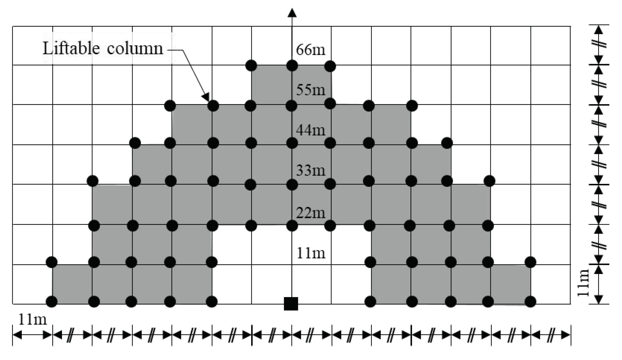
The liftable columns are analyzed based on the working radius of the crane, as illustrated in
Figure 10. Thus, columns of 21.76 m or more and 69.07 m or less are derived based on the boom head of the crane. This confirms that the assumption regarding the definition of the column position is incorrect, as shown in
Table 1, which is set at the beginning of the study. For example, the coordinates of C9 in
Figure 6b and
Table 1 are (11,0,10), which is a column located at a horizontal distance of 11 m. As this column is not located at 21.76 m or more and 69.07m or less, it cannot be erected with the crawler crane used in this study. The crane-moving process analyzed in
Figure 8 is shown in
Figure 9. First, a crane is installed 55 m from the members to be erected; second, the members are erected in a cascade manner. The members are installed via sequential movement of the crane by 11 m. Finally, the erection of the PC members is completed by positioning the crane at 22 m considering the crane lifting distance. In other words, the crane position coordinates (0,0,0) defined in equation (1) are newly redefined as the crane moves by 11m.
Figure 6.
Liftable PC columns analysis.
Figure 6.
Liftable PC columns analysis.
Figure 7.
Crane-moving process for erection of PC members.
Figure 7.
Crane-moving process for erection of PC members.
5.2. PC member erection sequence algorithm
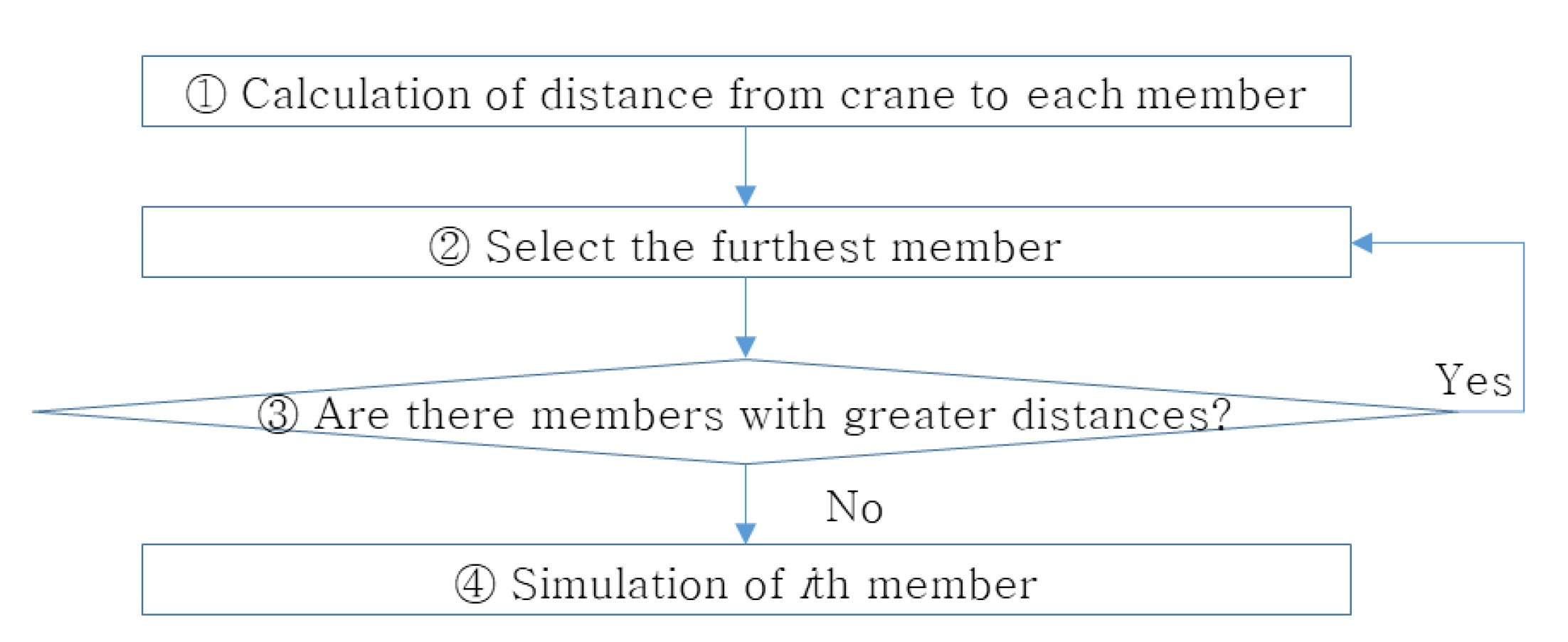
An algorithm for the PC member erection sequence is developed to perform the simulations, as shown in
Figure 10. This algorithm can be applied to all the PC columns and beam members. The erection of one member is defined as one simulation. This implies that the number of simulations increased with the number of members.
Figure 5.
Sequence algorithm for member erection
Figure 5.
Sequence algorithm for member erection
1) Calculating the distance from the crane to each member
The distance from the crane to each member was calculated using the defined position coordinates of the crane and member using the following equation:
|
= total linear distance from the crane to the erected member |
|
= coordinate of the erected member |
|
= coordinate of the erected member |
|
= coordinate of the erected member |
|
= coordinate of the crane |
|
= coordinate of the crane |
|
= coordinate of the crane |
|
= number of ith erected members at the crane position (1, …, n) |
2) Selection of the farthest member
To reduce interference with the erected members during the erection of PC members, PC members are erected in descending order of the linear distance from the crane to the member. Consequently, the member with the largest distance is selected from among the currently erected members.
3) Are there members with greater distances?
The erection simulation is performed if the selected member has the largest distance from the crane to the member among the non-erected members. However, if there is a member whose distance from the crane to the member is greater than that of the selected member, then the member should be selected.
4) Simulation of the ith member
Erection simulations are performed using the selected members. If there are members at the same distance, then they must be erected in descending order of angle from the trailer to the member. This is to reduce the interference of the members to be erected with already erected members. If Equations (20) and (21) are in conflict with each other, Equation (21) is prioritized. A simulation is performed for the total number of members and then sequentially according to the distance. When all the members are erected, the member installation sequence algorithm is completed.
5.3. Simulation results
Before starting the simulation, the position of the trailer is selected as (0, −33, 92). By reflecting the position of the trailer, the head of the boom is positioned 33 m from the crane, and the lifting of the PC members begins at this position. This position is calculated as 92 m in height due to the 97.74-m length of the boom. The trajectory distance of each column member can be calculated using Equations (1)–(11) based on the coordinate values (see
Table 1) of PC member position definition on sample ⓐ in
Figure 6(b) as follows. The horizontal rotation angle is calculated using Equations (1) and (2), and the horizontal rotation distance is calculated using Equation (3). Moreover, the vertical rotation angle is calculated using Equations (4)–(9), and the vertical rotation distance is calculated using Equation (10). Finally, the total trajectory distance of the boom can be calculated using Eq. (11). For example, the horizontal rotation angle of C1 among the column members is 153°, and the horizontal trajectory distance at this angle is 88 m. The vertical rotation angle of this member is 0.09°, and the vertical trajectory distance is 9 m. Hence, the total trajectory distance is 97 m. However, according to the liftable PC column analysis results in
Figure 8, only columns at 21.76 m or more and 69.07 m or less can be lifted. Hence, not all values derived from
Table 2 can be applied. Therefore, only C3, C4, C7, C8, C11, and C12 can be lifted at the crane position.
Based on the aforementioned analysis results,
Figure 11,
Figure 12 and
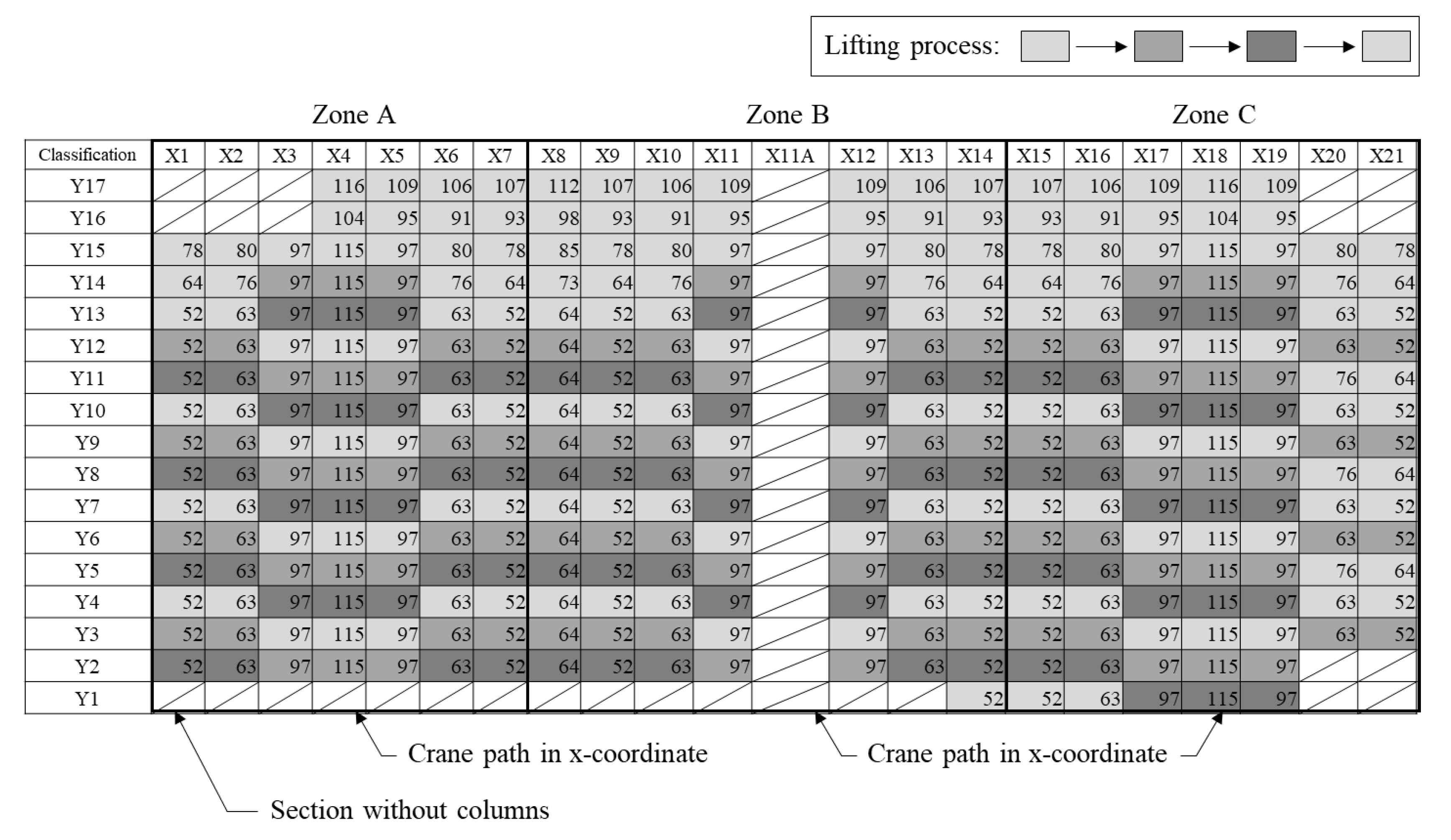
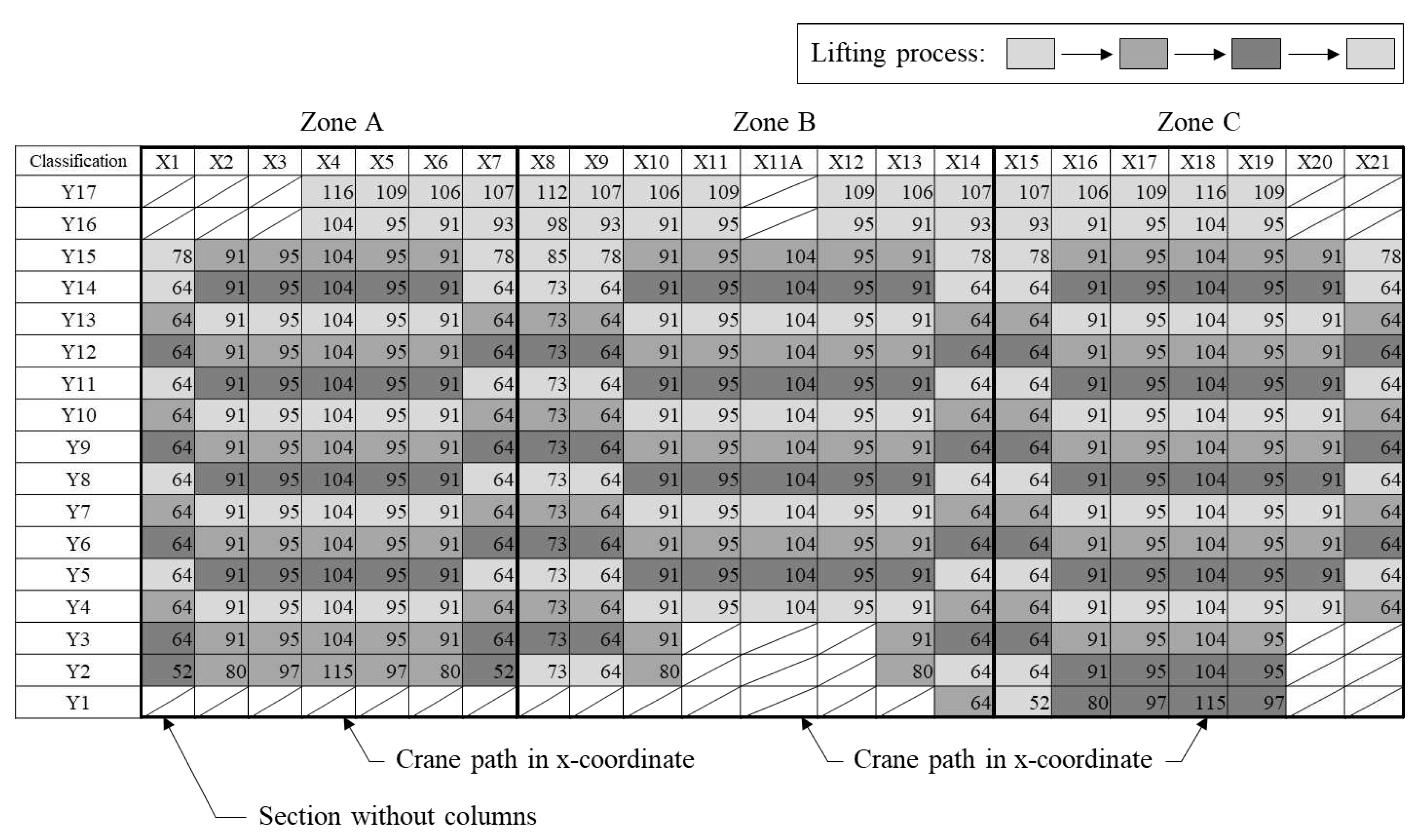
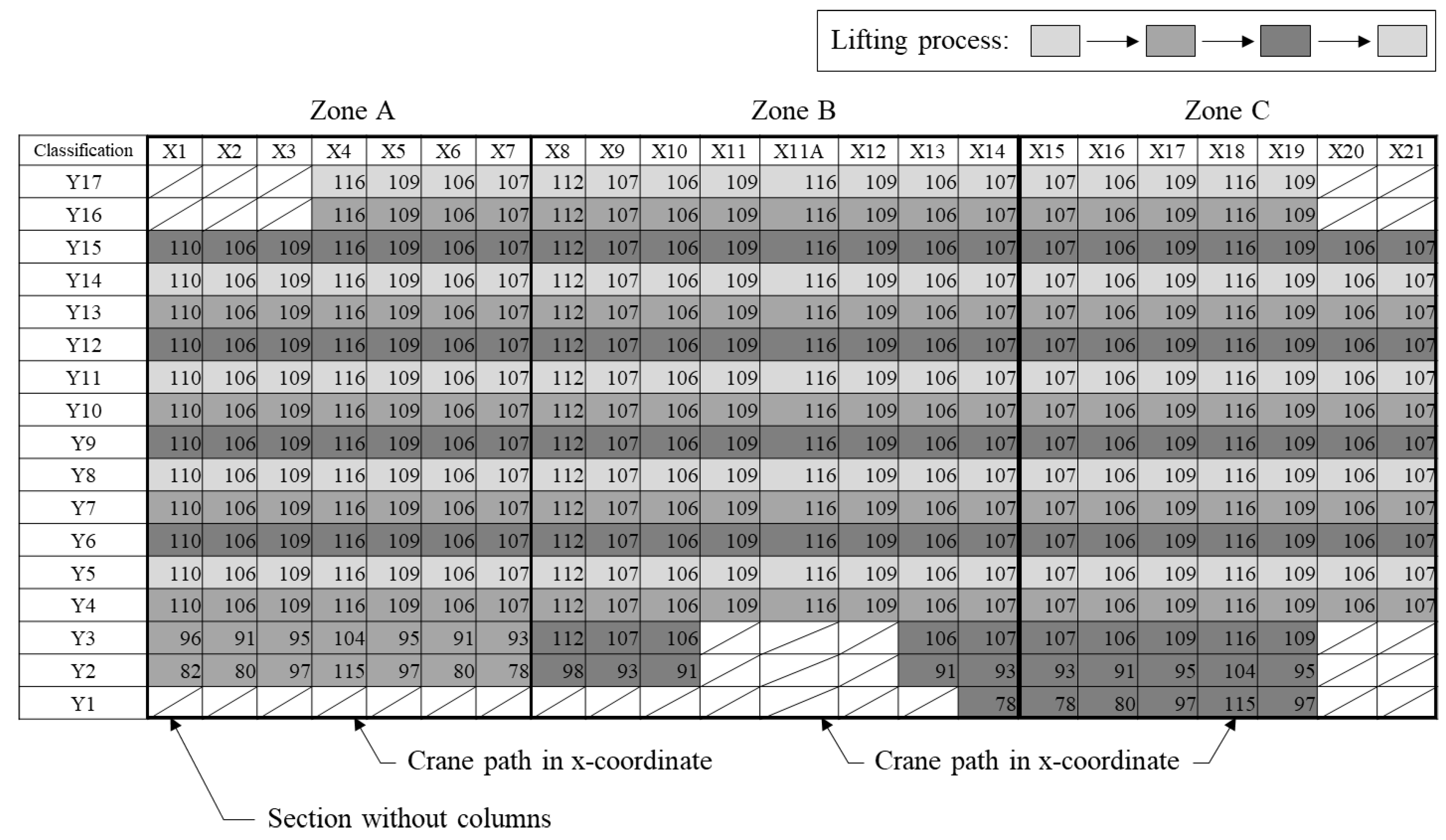
Figure 13 show the calculation of the trajectory distance of the column members for the crane path from the first to the third floor. The trajectory distance of each member complies with the rules of the crane-moving process for PC member erection shown in
Figure 9, and the total trajectory distance is determined as 183,575 m. The location with the farthest linear distance from the crane is expected to show the largest trajectory distance. However, it is observed that the trajectory distance is not large even if the linear distance from the crane is large. The location with the largest trajectory distance corresponds to that with the largest horizontal movement, where it shows the same x-coordinate as the trailer. Furthermore, the trajectory distance is not the smallest when the linear distance is the smallest. Among the members that can be lifted by the crane, the member at the position, where the horizontal movement is smallest, shows the smallest value. The trajectory distance can be easily calculated because it shows a consistent pattern based on the crane movement. This is due to the fact that the members are positioned at distances of 11 or 18 m due to the characteristics of large logistic buildings.
Figure 9.
Trajectory distance on the first floor.
Figure 9.
Trajectory distance on the first floor.
The crane is removed by sequentially erecting its members. However, as the last members of the second and third floors are not required to be erected in a cascade manner, as shown in
Figure 11 and
Figure 12, they can be simultaneously erected without moving the crane. However, additional Y-column members must be installed on the opposite side of Zone B. Thus, their erection must be completed by moving them. Moreover, given that the third floor is the last floor of the PC structure, PC members can be erected without considering the connection with other floors as shown in
Figure 12.
Figure 6.
Trajectory distance on the second floor.
Figure 6.
Trajectory distance on the second floor.
Figure 11.
Trajectory distance on the third floor.
Figure 11.
Trajectory distance on the third floor.
The average unit erection time for each PC member at the case site is 40 min, 15 min, and 10 min for columns, beams, and slabs, respectively. The number of members is 850, 1,371, and 4,032, respectively. Furthermore, the actual erection time is 210 calendar days, and the rotation distance of the crane is 20 m/min. After excluding the time required to fix the position of the members, the actual and simulated times required for PC member erection are 172 and 158 days, respectively. Thus, a 13.99% reduction in the construction period is possible.
With respect to cost comparison, labor, material, and equipment costs are summed [
58] using Equations (22) and (23). Labor, material, and equipment costs are calculated using Equations (24)–(26). The actual cost of PC member erection in
Table 2 denotes the results of the calculation using the actual input quantity. The simulation-calculated cost in
Table 3 shows the results of the calculation reflecting the actual cost. With respect to the unit price of the labor cost, the amount from the “Construction Industry Wage Survey Report (Market Wage Unit Price) applied to the first half of 2022” is applied. Material and equipment costs are calculated based on the unit price applied in the field. Hence, the actual cost is
$6,221,704, and the simulation-calculated cost is
$5,710,335. Therefore, when applying the model developed in this study, the cost can be reduced by 8.33% when compared to the actual construction cost. In terms of equipment cost, the actual and simulation-calculated costs accounted for 89% and 90%, respectively, showing the highest proportions of construction costs. This implies that the daily rent for the crane accounted for the highest percentage. Therefore, to reduce construction costs, the minimum rental dates should be applied by deriving accurate dates when the crane is used before starting construction.
|
= Total cost of the boom trajectory |
|
= Direct cost of the boom trajectory |
|
= Indirect cost of the boom trajectory |
|
= Labor cost of the boom trajectory |
|
= Material cost of the boom trajectory |
|
= Equipment cost of the boom trajectory |
Table 3.
Actual cost for erection of PC members
Table 3.
Actual cost for erection of PC members
| Item |
Unit |
Quantity |
Unit price ($) |
Amount ($) |
| Labor cost |
Equipment operator |
Day |
172 |
229 |
39,388 |
| Common labor |
Day |
516 |
154 |
79,464 |
| Material cost |
Diesel |
L |
12,900 |
1.83 |
25,437 |
| Equipment fee |
Crane (550 ton) |
Day |
430 |
13,000 |
5,590,000 |
| Indirect cost |
487,15 |
| Total |
6,221,704 |
Table 4.
Simulation-calculated cost the erection of PC members
Table 4.
Simulation-calculated cost the erection of PC members
| Item |
Unit |
Quantity |
Unit price ($) |
Amount ($) |
| Labor cost |
Equipment operator |
Day |
158 |
229 |
36,182 |
| Common labor |
Day |
474 |
154 |
72,996 |
| Material cost |
Diesel |
L |
10,275 |
1.83 |
18,803 |
| Equipment fee |
Crane (550 ton) |
Day |
395 |
13,000 |
5,135,000 |
| Indirect cost |
447,353 |
| Total |
5,710,335 |
|
= labor cost of the boom trajectory |
|
= material cost of the boom trajectory |
|
= equipment cost of the boom trajectory |
|
= quantity of the ith columns |
|
= unit labor cost for column erection |
|
= number of ith beams |
|
= unit labor cost for beam erection |
|
= number of ith slabs |
|
= unit labor cost for slab erection |
|
= unit material cost for column erection |
|
= unit material cost for beam erection |
|
= unit material cost for slab erection |
|
= unit equipment cost for column erection |
|
= unit equipment cost for beam erection |
|
= unit equipment cost for slab erection |
|
= number of erected ith columns (1, …, n) |
| j |
= number of erected ith beam members (1, …, m) |
|
= number of erected ith slab members (1, …, l) |
CO
2 emissions are calculated, as shown in
Table 5, using the labor, material, and equipment costs and the indirect cost calculated in
Table 3 and
Table 4. The CO
2 emissions corresponding to the direct cost are calculated using actual input labor, oil, and electricity use. Furthermore, the CO
2 emissions corresponding to indirect costs are calculated using actual input lighting, heating use, and environmental conservation. Consequently, when the model developed in this study is applied, 25.99% of CO
2 emissions can be reduced when compared to actual construction. Equations (27)–(30) show that the total CO
2 emissions can be derived by multiplying the number of PC members by the unit CO
2 emission of each item. In terms of oil use, the actual and simulation-calculated plans accounted for 99% and 98%, respectively, indicating high CO
2 emissions.
|
= total CO2 emission |
|
= CO2 emission of column |
|
= CO2 emission of beam |
|
= CO2 emission of slab |
|
= number of ith columns |
|
= unit CO2 emission of labor |
|
= unit CO2 emission of oil |
|
= unit CO2 emission of electricity |
|
= unit CO2 emission of lighting and heating |
|
= unit CO2 emission of environmental conservation |
|
= number of ith beams |
|
= number of ith slabs |
|
= number of erected ith columns (1, …, n) |
|
= number of erected ith beams (1, …, m) |
|
= number of erected ith slabs (1, …, l) |
Energy consumption is calculated, as shown in
Table 6, using the oil and electricity consumption presented in
Table 3 and
Table 4. The electrical energy consumption is calculated using Equation (31), and the actual diesel input is converted into the SI base unit for energy. For the capacity of the 550-t crane, 397 kW is applied, and for the energy conversion value of diesel, 41,090/m3 is applied. Hence, the simulation calculated for member erection can reduce energy consumption by 26.01 %. In terms of oil use, the actual and simulated plans accounted for more than 99%, indicating high energy consumption.
|
= energy consumption |
|
| P |
= power (kW) |
|
| t |
= time (s) |
|
| |
|
|
|
|
The simulation-calculated plan shows a reduction effect in terms of construction time, cost, CO2 emissions, and energy use when compared with the actual plan. These ratios are not the same because the constituent items and composition ratios differ. Furthermore, CO2 emissions and energy consumption are reduced by 25.99% and 26.01%, respectively, indicating high reduction rates. Therefore, minimization of the crane usage rate at a site has a considerable effect in preventing environmental pollution.
6. Conclusions
In this study, the time required for each activity in the construction process was analyzed to investigate the developed productivity analysis method. The analysis results were then compared with those of the current construction method in terms of time and cost. The conclusions obtained in this study are as follows:
First, the existing algorithm is widely applied in the construction field and, depends only on labor experience. Hence, the method and order of specific crane work are determined right before work. However, this study proposed a mathematical model for calculating the trajectory distance so that crane work can be planned and simulated in advance. In other words, it solved the problem of crane work based on experience.
Second, by calculating the trajectory distance of the column member, the trajectory distance for each member complied with the rules of the crane-moving process for PC member erection assumed in this study. A total trajectory distance of 183,575 m was derived from this calculation. In this study, the farthest linear distance from the crane was expected to show the largest trajectory distance. However, it was confirmed that the trajectory distance was not large even when the linear distance from the crane was large. The location with the largest trajectory distance corresponded to that with largest horizontal movement, which had the same x-coordinate as the trailer.
Third, by calculating the trajectory distance, the smallest trajectory distance was not derived when the linear distance from the crane was the smallest. Among the members that can be lifted by the crane, the member with the intermediate distance showed the smallest value. This is due to the fact that as the linear distance from the crane decreases, the vertical rotation distance increases, and thereby, the smallest value was not observed.
Fourth, a consistent pattern of the trajectory distance, according to crane movement, can be derived, thereby making the calculation easier. The reason for showing a certain pattern was that the column members had distances of 11 or 18 m because of the characteristics of a large logistic building.
Fifth, actual and simulated plans were compared by applying them to a case site. The simulation-calculated plan showed a reduction of 13.99% in construction period, 8.33% in cost, 25.99% in CO2 emission, and 26.01% in energy consumption when compared to the actual plan. Furthermore, CO2 emissions and energy use showed high reduction rates, suggesting that the minimization of the crane usage rate at the site had a considerable effect in preventing environmental pollution.
In this study, rules for the location of cranes and members were established, and equations for calculating the distance between cranes and members were derived and simulated. This can be used as basic data for research on PC erection. In addition, through this study, the problem of crane work based only on experience at the construction site was solved, and the developed model can streamline the construction process, reduce time and cost, and enhance productivity. Additional research can be conducted to verify the efficiency of the developed model via trajectory distance calculations based on various scenarios across a variety of fields. The cost, construction time, CO2 emissions, and energy consumption can be easily calculated using the developed model, and the shortest distance according to field conditions can be optimized by developing simulation and optimization models in the future. They can be automatically calculated using the developed model, and the shortest distance can be automatically derived based on the calculated data. Furthermore, errors due to human calculation can also be prevented. Additionally, in this study, the boom and jib of the crane were not distinguished, and the energy and cost required to move the trailer were not investigated in detail. Therefore, additional research should be conducted in the future by clearly defining the rotational distances of the boom and jib of the crane and collecting data on the movement of the trailer.
Author Contributions
Conceptualization, S.K.; methodology, S.K. and J.L.; validation, J.L.; formal analysis, S.K. and J.L.; investigation, J.O. and J.L.; data curation, J.L.; writing—original draft preparation, J.L.; writing—review and editing, S.K. and J.L.; visualization, J.O. and J.L.; supervision, S.K. and J.L.; project administration, S.K. and J.L.; funding acquisition, J.L. All authors have read and agreed to the published version of the manuscript.
Funding
This work was supported by the National Research Foundation of Korea (NRF) grant funded by the Korea government (MOE) (No. 2021R1C1C2094527).
Conflicts of Interest
The authors declare no conflict of interest.
References
- Lim, J.; Kim, D.Y. Integrated management model of production and yard stock for in-situ precast concrete production, J. Asian Archit. Build. Eng 2021, 23, 1–17. [Google Scholar] [CrossRef]
- S.M. Kang, O.J. S.M. Kang, O.J. Kim, Domestic and foreign present situation analysis of a PC method, Daelim Technol. Res. Inst. Archit. (Spring) (2006) 28–37.
- Badir, Y.F.; Kadir, M.R.A.; Hashim, A.H. Industrialized building systems construction in Malaysia, J. Archit. Eng. 2002, 8, 19–23. [Google Scholar] [CrossRef]
- Chan, W.T. Chan, W.T.; Hu,H. Constraint programming approach to precast production scheduling, J. Constr. Eng. Manag. 2002, 128, 513–521. [Google Scholar] [CrossRef]
- Eastman, C.M.; Sacks,R. Relative productivity in the AEC industries in the United States for on-site and off-site activities. J. Constr. Eng. Manag. 2008, 134, 517–526. [CrossRef]
- Kwon, H.; Jeon, S.; Lee, J.; Jeong, K. Development of a simulation model for supply chain management of precast concrete. Korean Journal of Construction Engineering and Management 2021, 22(5), 86–98. [Google Scholar] [CrossRef]
- Lee, S.; Cha, H. A study on plans for diffusion & revitalization, and developing key performance indicator for OSC based PC structure apartment housing. Korean Journal of Construction Engineering and Management 2021, 22(1), 98–105. [Google Scholar] [CrossRef]
- Lim, J.; Son, C.B.; Kim, S. Scenario-based 4-D dynamic simulation model for in-situ production and yard stock of precast concrete members. J. Asian Arch. Build. Eng 2023, 22(4), 2320–2334. [Google Scholar] [CrossRef]
- Kim, W.; Lee, D. Wall Structure Combination and Ramen Structure PC Combination Method. J, Korea Institute Building Constr. 2002, 2(2), 84–88. [Google Scholar]
- Shin, D.W.; Kim, C.D. A typological study on performance defects of PC apartment housing. Journal of the Architectural Institute of Korea 1993, 10, 123–130. [Google Scholar]
- An, S.H.; Lee, U.K.; Kang, K.I. A study on the proposal about the improvement of PC in construction industry, J. Archit., Institute Korea 2004, 20(7), 135–142.
- Jin, E.; Park, S.; Chae, M.; Han,S. Decision making model for application of manufacturing production system in construction project, Proc. 2004 Autumn Annual Conf. Korea Inst. Constr, Eng. Manag. (2004) 515–520.
- Kim, M.; Yoon, I.; Kim, N.; Park, M.; Ahn, C.; Jung, M. A study on virtual environment platform for autonomous tower crane. Korean Journal of Construction Engineering and Management 2022, 23(4), 3–14. [Google Scholar] [CrossRef]
- Kale, S.; Arditi, D. Diffusion of ISO 9000 certification in the precast concrete industry. Constr. Manag. Econ. 2006, 24, 485–495. [CrossRef]
- Polat, G. Factors affecting the use of precast concrete systems in the United States, J. Constr. Eng. Manag. 2008, 134, 169–178. [Google Scholar] [CrossRef]
- Yee, A.A.; Eng, H.D. Structural and economic benefits of precast/prestressed concrete construction. PCI J. 2001, 46, 34–42. [Google Scholar] [CrossRef]
- Yun, W.G.; Shin, E.Y.; Kang, T.K. A study on virtual environment platform for autonomous tower crane. Korean Journal of Construction Engineering and Management 2021, 22(6), 55–63. [Google Scholar] [CrossRef]
- Kang, H.J. 2008, A Study of Ship Design Process Optimization in a Concurrent Engineering Environment, Seoul National University, South Korea, Master’s thesis.
- Lim, J.; Kim, S. Evaluation of CO2 emission reduction effect using in-situ production of precast concrete components, J. Asian Archit. Build. Eng. 2020a, 19, 176–186. [Google Scholar] [CrossRef]
- Lim, J.; Kim, J.J. Dynamic optimization model for estimating in-situ production quantity of PC members to minimize environmental loads, Sustainability 2020b, 12, 8202. [CrossRef]
- Lim, J.; Kim, S.; Kim, J.J. Dynamic simulation model for estimating in-situ production quantity of PC members, Int. J. Civ. Eng. 2020, 18, 935–950. [Google Scholar] [CrossRef]
- Guo, H.; Zhou, Y.; Pan, Z.; Zhang, Z.; Yu, Y.; Li, Y. Automated selection and localization of mobile cranes in construction planning. Buildings 2022, 12, 580. [Google Scholar] [CrossRef]
- Kang, S.; Miranda, E. Planning and visualization for automated robotic crane erection processes in construction, Autom. Constr. 2006, 15, 398–414. [Google Scholar] [CrossRef]
- Lacey, A.W.; Chen, W.; Hao, H.; Bi, K. Structural response of modular buildings–An overview, J. Build. Eng. 2018, 16, 45–56. [Google Scholar] [CrossRef]
- Jang, J.Y.; Cho, K.W.; Koo, C.; Lee, C.; Kim, T. Importance and Performance Analysis on Factors of PC Component Allocation and Loading Planning. Korean Journal of Construction Engineering and Management 2022, 22(2), 53–62. [Google Scholar] [CrossRef]
- Olearczyk, J.; Al-Hussein, M.; Bouferguene, A.; Telyas, A. 3D-modeling for crane selection and logistics for modular construction on-site assembly. Computing in Civil Engineering 2012, 445–452. [Google Scholar] [CrossRef]
- Lim, J.; Park, K.; Son, S.; Kim, S. Cost reduction effects of in-situ PC production for heavily loaded long-span buildings, J. Asian Archit. Build. Eng. 2020b, 19, 242–253. [Google Scholar] [CrossRef]
- Lei, Z.; Han, S. A.; Bouferguène, H. Taghaddos, U. Hermann, M. Al-Hussein, Algorithm for mobile crane walking path planning in congested industrial plants. J. Constr. Eng. Manag. 2015, 141, 05014016. [Google Scholar] [CrossRef]
- Tam, C.M.; Tong, T.K.L.; Chan, W.K.W. Genetic algorithm for optimizing supply locations around tower crane, J. Constr. Eng. Manag. 2001, 127, 315–321. [Google Scholar] [CrossRef]
- Al-Hussein, M.; Alkass, S.; Moselhi, O. Optimization algorithm for selection and on site location of mobile cranes, J. Constr. Eng. Manag. 2005, 131, 579–590. [Google Scholar] [CrossRef]
- Safouhi, H.; Mouattamid, M.; Hermann, U. A. Hendi, An algorithm for the calculation of feasible mobile crane position areas, Autom. Constr. 2011, 20, 360–367. [Google Scholar] [CrossRef]
- Hanna, A.S.; Lotfallah, W.B. A fuzzy logic approach to the selection of cranes, Autom. Constr. 1999, 8, 597–608. [Google Scholar] [CrossRef]
- Sawhney, A.; Mund, A. Adaptive probabilistic neural network-based crane type selection system, J. Constr. Eng. Manag. 2002, 128, 265–273. [Google Scholar] [CrossRef]
- Wu, D.; Lin, Y.; Wang, X.; Wang, X.; Gao, S. Algorithm of crane selection for heavy lifts, J. Comput. Civ. Eng. 2011, 25, 57–65. [Google Scholar] [CrossRef]
- Al-Hussein, M.; Athar Niaz, M.A.; Yu, H.; Kim, H. Integrating 3D visualization and simulation for tower crane operations on construction sites, Autom. Constr. 2006, 15, 554–562. [Google Scholar] [CrossRef]
- Lin, Y.; Wu, D.; Wang, X.; Wang, X.; Gao, S. Statics-based simulation approach for two-crane lift, J. Constr. Eng. Manag. 2012, 138, 1139–1149. [Google Scholar] [CrossRef]
- Taghaddos, H.; AbouRizk, S.; Mohamed, Y.; Hermann, U. Simulation-based auction protocol for resource scheduling problems, J. Constr. Eng. Manag. 2012, 138, 31–42. [Google Scholar] [CrossRef]
- Taghaddos, H.; Hermann, U.; AbouRizk, S.; Mohamed, Y. Simulation-based multiagent approach for scheduling modular construction, J. Comput. Civ. Eng. 2014, 28, 263–274. [Google Scholar] [CrossRef]
- Al-Bahnassi, H.; Hammad, A. Near real-time motion planning and simulation of cranes in construction: Framework and system architecture, J. Comput. Civ. Eng. 2012, 54–63. [Google Scholar] [CrossRef]
- Sivakumar, P.L.; Varghese, K.; Babu, N.R. Automated path planning of cooperative crane lifts using heuristic search, J. Comput. Civ. Eng. 2003, 17, 197–207. [Google Scholar] [CrossRef]
- Olearczyk, J.; Al-Hussein, M.; Bouferguene, A.; Telyas, A. 3D-modeling for crane selection and logistics for modular construction on-site assembly, in: J. Comput. Civ. Eng., American Society of Civil Engineers, Reston, Virginia (2012) 445–452. [CrossRef]
- Zhang, C.; Hammad, A. Multiagent approach for real-time collision avoidance and path replanning for cranes, J. Comput. Civ. Eng. 2012, 26, 782–794. [Google Scholar] [CrossRef]
- Lei, Z.; Taghaddos, H.; Hermann, U.; Al-Hussein, M. A methodology for mobile crane lift path checking in heavy industrial projects, Autom. Constr. 2013, 31, 41–53. [Google Scholar] [CrossRef]
- Lei, Z.; Taghaddos, H.; Olearczyk, J.; Al-Hussein, M.; Hermann, U. Automated method for checking crane paths for heavy lifts in industrial projects, J. Constr. Eng. Manag. 2013, 139, 04013011. [Google Scholar] [CrossRef]
- Hasan, S.; Zaman, H.; Han, S.; Al-Hussein, M.; Su, Y. Integrated building information model to identify possible crane instability caused by strong winds, in: Proc., Construction Research Congress, American Society of Civil Engineers, Reston, Virginia, 2012, pp. 1281–1290. [CrossRef]
- Huang, C.; Wong, C.K.; Tam, C.M. Optimization of tower crane and material supply locations in a high-rise building site by mixed-integer linear programming, Autom. Constr. 2011, 20, 571–580. [Google Scholar] [CrossRef]
- Al-Hussein, M.; Alkass, S.; Moselhi, O. An algorithm for mobile crane selection and location on construction sites, Constr. Innov. 2001, 1, 91–105. [Google Scholar]
- Hasan, S.; Al-Hussein, M.; Hermann, U.H.; Safouhi, H. Interactive and dynamic integrated module for mobile cranes supporting system design, J. Constr. Eng. Manag. 2010, 136, 179–186. [Google Scholar] [CrossRef]
- Moselhi, O.; Alkass, S.; Al-Hussein, M. Innovative 3D-modelling for selecting and locating mobile cranes, Eng. Constr. Archit. Manag. 2004, 11, 373–380. [Google Scholar] [CrossRef]
- Reddy, H.R.; Varghese, K. Automated path planning for mobile crane lifts, Comput. Aid. Civ. Infrastruct. Eng. 2002, 17, 439–448. [Google Scholar] [CrossRef]
- Chang, Y.; Hung, W.; Kang, S. A fast path planning method for single and dual crane erections, Autom. Constr. 2012, 22, 468–480. [Google Scholar] [CrossRef]
- Son, S.; Lim, J.Y.; Kim, S.K. Erection simulation of steel connected precast concrete components for long span and heavy loaded logistics buildings, in: 3rd World Congress on Civil, Structural, and Environmental Engineering, CSEE, Budapest, Hungary, 2018. [CrossRef]
- Lee, H.-H.; Kim, K.-H.; Son, S.; Park, K.; Kim, S. Time reduction effects of steel connected precast concrete components for heavily loaded long-span buildings, J. Civ. Eng. Manag. 2020, 26, 160–174. [Google Scholar] [CrossRef]
- Nawy, E.G. Concrete Construction Engineering Handbook, CRC Press, 2008. [CrossRef]
- Lim, C.Y.; Joo, J.K.; Lee, G.J.; Kim, S.K. In-situ production analysis of composite precast concrete members of green frame, Journal of the Korea Institute of Building Construction. Korea Institut Building Constr. 2011, 11, 501–514. [Google Scholar] [CrossRef]
- Kim, S.H.; Choi, E.G.; Kim, S.K.; Lee, S.H. A case study of the improvement of the structural work of a logistics facility by using PC member, Journal of the Korea Institute of Building Construction. Korea Institut Building Constr. 2010, 10, 127–135. [Google Scholar] [CrossRef]
- Park, S.; Kim, T.W.; Son, B. Quantitative Analysis of Construction Site Layout: A Usability Evaluation Study, Korea Journal of Construction Engineering and Management. 23(5) (2022) 34-42. [CrossRef]
- Lee, J.H.; Tae, Y.H.; Baek, S.H.; Kim, K. A study of improvements in the standards of cost estimate for the new excellent technology in construction, Korea Journal of Construction Engineering and Management 2022, 23(5), 65-76. [CrossRef]
|
Disclaimer/Publisher’s Note: The statements, opinions and data contained in all publications are solely those of the individual author(s) and contributor(s) and not of MDPI and/or the editor(s). MDPI and/or the editor(s) disclaim responsibility for any injury to people or property resulting from any ideas, methods, instructions or products referred to in the content. |
© 2023 by the authors. Licensee MDPI, Basel, Switzerland. This article is an open access article distributed under the terms and conditions of the Creative Commons Attribution (CC BY) license (http://creativecommons.org/licenses/by/4.0/).
