1. Introduction
Laser communication technology has the advantages of wide bandwidth, large capacity, compact terminal structure, low power consumption, anti-eavesdropping, and anti-jamming [
1], and has been gradually applied to military defense [
2,
3] civilian emergency communication [
4] satellite communication [
5,
6,
7] and deep space exploration [
8,
9,
10] and many other fields have become new research hotspots in the field of communication . However, when the laser communication link is transmitted through the atmosphere, due to the presence of atmospheric turbulence effect leads to serious interference with the communication performance and stability of laser communication [
11,
12]. The coupling efficiency problem under atmospheric turbulence interference constrains the application of laser communication in the atmosphere. Coupling efficiency is a key factor in determining the final communication quality of atmospheric laser links. The laser beam must therefore be coupled into a single-mode fiber in order to use single-mode fiber-based fiber amplifiers under atmospheric turbulence and also to be connected to ground fiber optic networks [
13]. In coherent optical systems, single-mode fiber coupling is also required. For free-space optical communications through atmospheric turbulence in the horizontal case, a theoretical description of the fiber coupling efficiency has been developed. Several techniques have been proposed to improve the coupling efficiency, such as coherent fiber array reception, adjusting the focus of the coupling system, adaptive optics (AO), and so on. The most common of these is the AO, which measures wavefront aberrations caused by turbulence.
In this paper, the fiber coupling efficiency model under horizontal transmission path is extended to the coupling efficiency model under inclined transmission path. Simulations are performed to analyze the coupling efficiency with respect to wavelength, zenith angle, receiving aperture and height above ground. In order to solve the problem of fiber coupling efficiency in the atmospheric slant-range channel, an adaptive optical system and a precision tracking system are used to improve the coupling efficiency, and the relationship between the coupling efficiency and the Strehl ratio (SR) is studied. A semi-physical simulation experiment system of atmospheric slant-range channel coupling efficiency was built to complete the coupling efficiency test and analysis.
2. Fiber coupling efficiency in slant atmospheric transmission path
In the star-ground link, the path of space optical coupling to SFM is shown in
Figure 1. Under the influence of atmospheric turbulence, spatial light passes through the ideal receiving antenna without aberration and converges to the back focus surface to form an Airy spot. Optical energy is coupled into a single-mode fiber core placed in the focal plane position.
The theory of the fiber coupling efficiency for horizontal laser communications is defined as the ratio of the average power coupling into the fiber
to the average power in the receiver aperture plane
and is given by[
14]
Where
is the incident optical field at the receiver aperture plane and
the mode field distribution of the normalized single-mode fiber. For plane waves and Kolmogorov power law spectra, the coupling efficiency of a single-mode fiber after atmospheric turbulence is generally expressed by the following equation [
15]
Where is the area of the receiver aperture, the receiver lens diameter. is the spatial coherence area of the incident plane wave, is the spatial coherence radius of horizontal path, the atmospheric refractive index structure, is the number of light waves, the unit is rad /m, is the wavelength. The ratio enotes the number of speckles over the receiver aperture area. is the ratio of the receiver lens radius to the radius of the backpropagated fiber mode. is zero order Bessel function.
The optimum value of the coupling-geometry parameter
that maximizes the coupling efficiency depends on the value of the number of speckles
. In the absence of turbulence, the incident plane wave is fully coherent and the optimum value of
is 1.12. It has been shown that if the lens focal length is chosen to satisfy
=1.12, corresponding to the optimum a value for a fully coherent incident plane wave, the coupling efficiency obtained for other values of
is not appreciably less than the maximum coupling efficiency that can be obtained by optimizing
[
15]. Therefore we use
=1.12 in the rest of the calculation. So coupling efficiency depends only on the spatial coherence radius. Developed and expanded to slant atmospheric transmission path on spatial coherence radius by using Eq.(3),(4) and (5). Equation (3) represents the Hufnagel-Vally (H-V) model of the refractive index structure constant of the atmosphere under slope link.
is the structure constant on ground, which are typical values for clear sky and weak turbulence conditions.
is the wind velocity, which can be calculated using the Bufton wind model[
16]:
The spatial coherence radius for slant atmospheric transmission path is calculated by(5)
Where, is the height above the ground, is the zenith angle. In addition, the relation between spatial coherence and Fried parameter will be used in the subsequent sections and it is expressed by .
It can be obtained from the above analysis coupling efficiency is the function of wavelength,receiver aperture ,height above the ground, and zenith angle. According to the parameters in
Table 1 the coupling efficiency in slant atmospheric transmission path was studied.
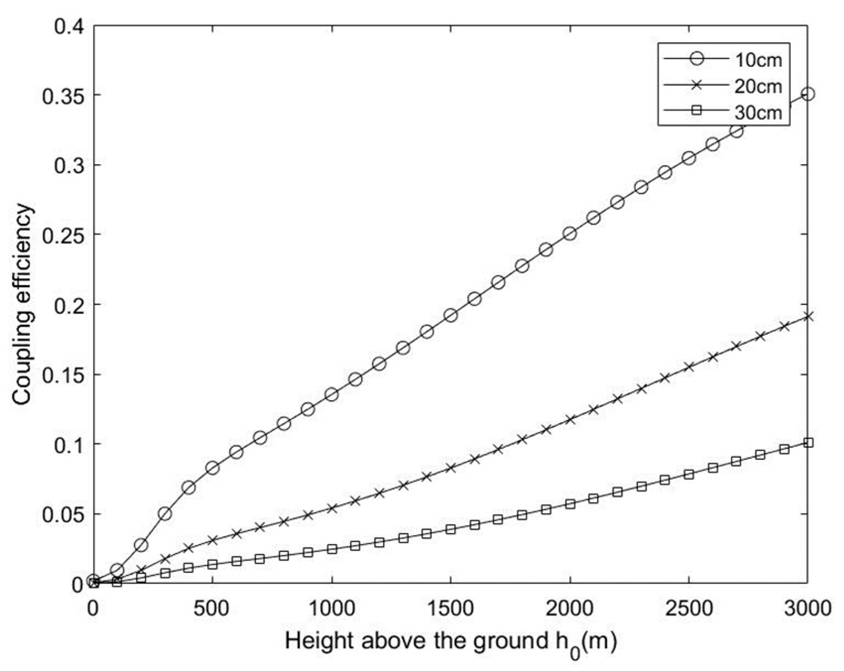
Figure 2 shows coupling efficiency as a function of the height above ground for D=10cm to 30cm. As can be seen from the result, the larger aperture than speckle patterns degrades the fiber coupling efficiency drastically; Therefore, to obtain higher fiber coupling efficiency, the aperture size corresponding to the atmospheric coherence size must be checked and correctly selected. On the other hand, the received power will be decreased when the mirror size is small. At the aperture greater than 30mm the coupling efficiency decreases quickly, and the height above the ground greater than 500m it grows slowly.
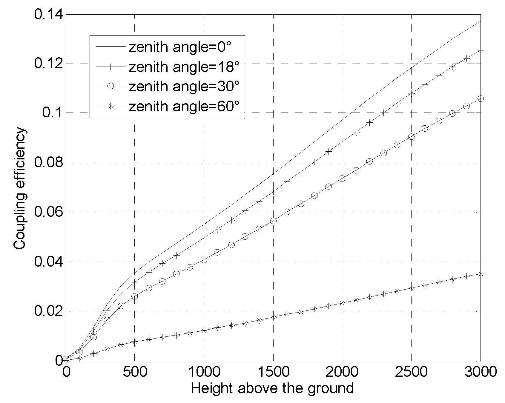
Figure 3 shows the coupling efficiency as a function of the height above ground for
=0°,18°,30°,60°. The efficiency is degraded to less than 22% when
change from 0°to 60°at h0=500m.
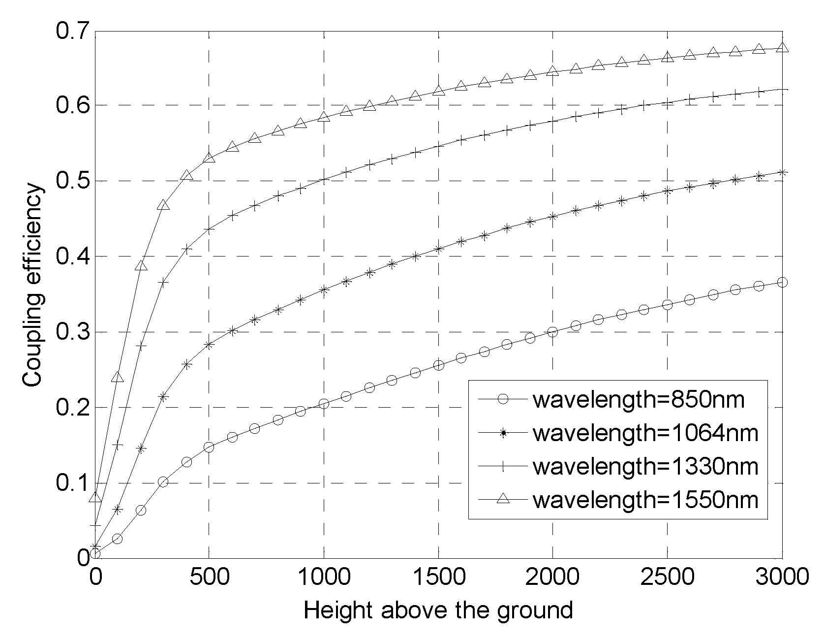
Figure 4 shows the coupling efficiency as a function of the height above ground for
=850nm, 1064nm, 1330nm, 1550nm. Long wavelengths are beneficial for improving coupling efficiency. At the height above the ground greater than 500m the coupling efficiency grows slowly.
3. AO correction for coupling efficiency
According to AO correction the coupling efficiency is improved by increasing the spatial coherence radius. For simplicity, here we restrict the attention to the case of modal AO correction by totally removing some Zernike aberration modes, the temporal response of AO system is not investigated, and it is assumed that the control bandwidth is unlimited.
3.1. Relationship between coupling efficiency and AO correction
In order to characterize the spatial variation of a wavefront in turbulence in a given time, zernike polynomials are used with a set of basis functions. According to Noll definition, a wavefront aberrations can be written as [
17]
Where
are coefficients of corresponding Zernike polynomials
. The effect of modal correction is that some of the decomposition coefficients vanish. When the first
Zernike terms have been corrected, the residual distortion in wavefront may be estimated with Noll expression for the average variance [
17]
Where 〈 〉 denotes an ensemble average, is the corresponding coefficient given by Noll for the correction degree, and .
Similarly, a generalized Fired parameter
is defined after a modal AO correction, which is the function of
and
, given by[
18]
It is obvious from Equation(8)when spatial coherence length and spatial coherence area are increased the coupling efficiency will be increased. The simulation with different correction degree is shown in
Figure 5.
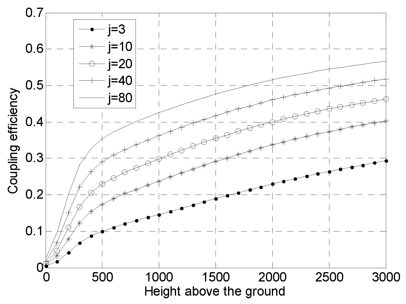
Figure 5 shows the coupling efficiency as a function of the height above ground for j=3, 10, 20, 40, 80. Compared with
Figure 1 the coupling efficiency is improved with AO system. When the correction degree is doubled the coupling efficiency is increased by approximately 5% at the height above ground greater than 500m.
For typical laser communication system the fine tracking system is necessary to keep in alignment between signal and detector. At the same time,when working in the atmosphere, the use of a fine tracking system eliminates the lower order terms of turbulent disturbances (j=3).
3.2. Relationship between coupling efficiency and SR
The SR is typical evaluation index to AO system, which is defined as the ratio of peak power in the center of the image plane compared to that of an equivalent unaberrated system.
where
is the imaging intensity of the focal spot on the optical axis,
is the light intensity at diffraction limit. Under general conditions, not limited to weak fluctuations, the SR can be approximated by the expression [
19,
20]
Using the relation
and
the Equation 11 can be rewritten as
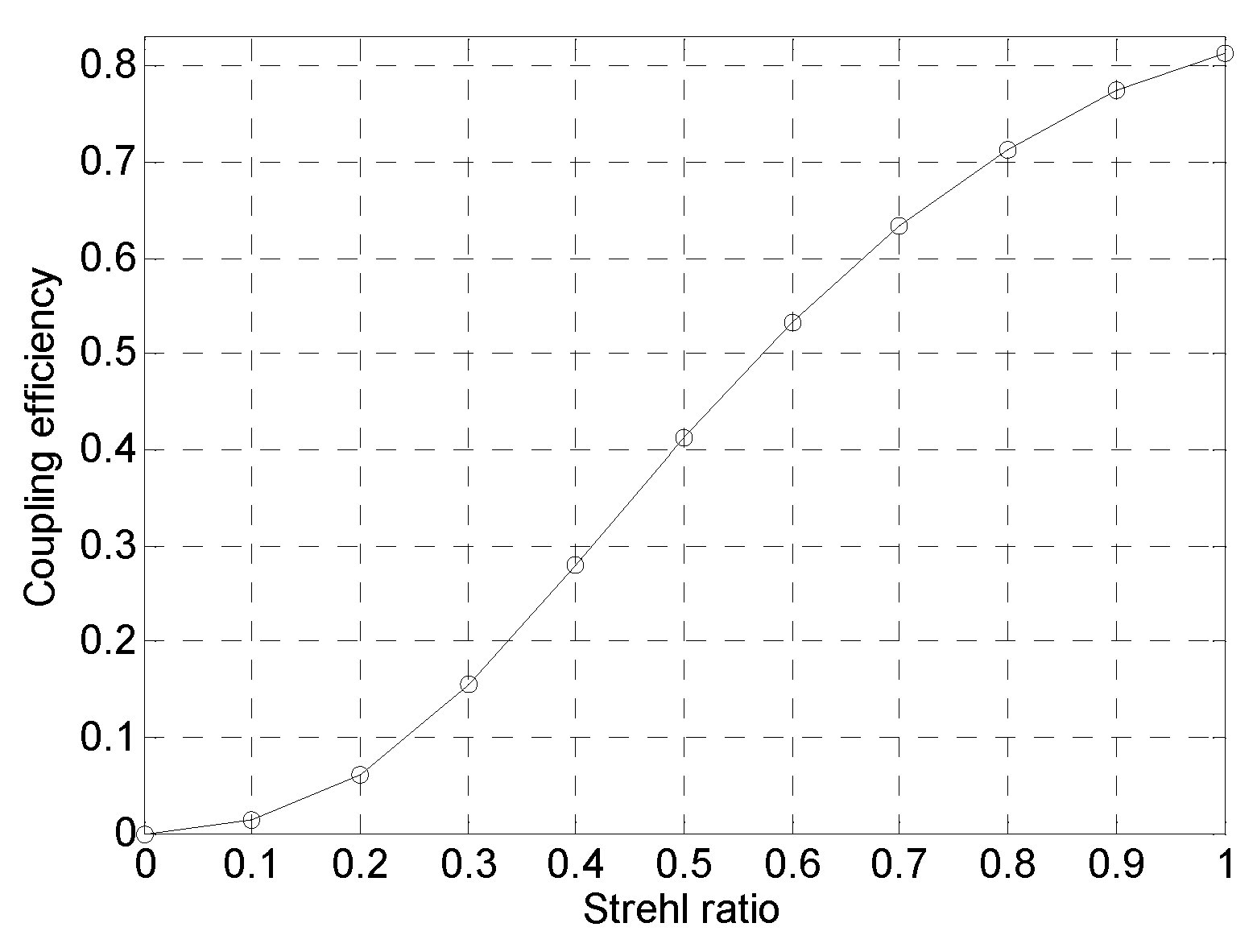
Substituting Equation 12 into Equation 2 the relationship between coupling efficiency and SR can be derived, and the simulation is shown in
Figure 6. The coupling efficiency can be estimated by SR. Particularly when the SR is between 0.1 and 0.9 the coupling efficiency is approximately
.
4. Semi-physical simulation experiment system.
4.1. Principle of system composition
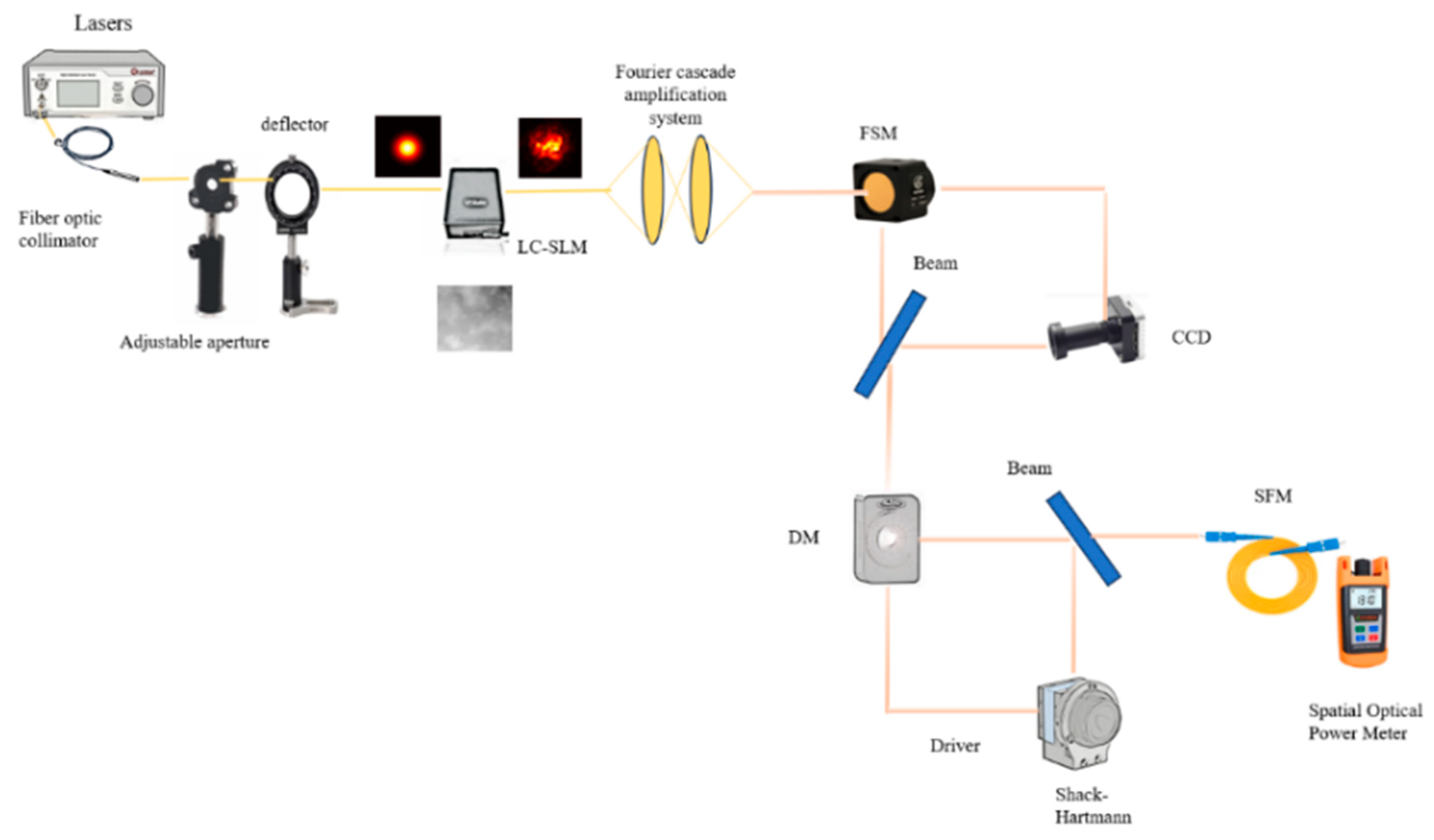
The semi-physical simulation experimental system of slant-range channel coupling efficiency consists of three parts: the transmitter side, the receiver side, and the slant-range link simulation. The slant link simulation is realized through a liquid crystal phase screen, which can simulate the intensity of turbulence, spatiotemporal distribution, etc. The receiving end is composed of a laser communication receiving optical system, a precision tracking system, an adaptive optical system, etc. The FSM, CCD is controlled as a closed loop, constituting a fine tracking system to eliminate the lower order terms of turbulence and adjust the laser beam so that it is controlled at the center of the CCD. DM, Hartmann sensor to form a closed-loop control, correct the wavefront aberration, suppress turbulence, the corrected beam coupled to a single-mode fiber and measured the received optical power. According to different parameter settings can be completed with different slant range, star-ground and other link coupling efficiency experimental testing. The basic principle is shown in
Figure 7.
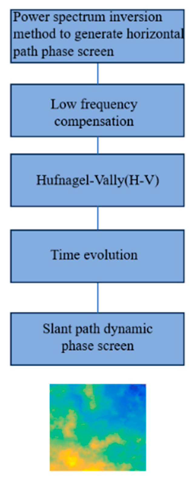
Among them, turbulence simulation is implemented in the following ways
Figure 8.
slant path phase screen.
Figure 8.
slant path phase screen.
4.2. Simulation experiment results
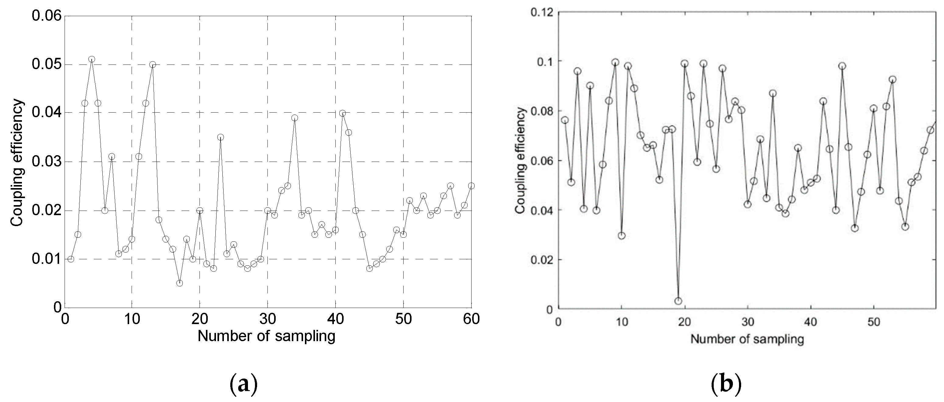
The parameters of the simulation system were set as follows: receiving optical aperture of 30 cm, conditions for the setup of the slant link (height above ground of 100 m, zenith angle of 30°, wavelength of 1550 nm, and turbulence intensity in the range of
). The number of fine tracking and adaptive optics correction higher order terms is j=40 and the test results are as follows. The coupling efficiency after fine tracking optical system is given in
Figure 9a and after adaptive optics in (b)
In the semi-physical simulation experimental system of the coupling efficiency of the slant-range channel, the mean value of the coupling efficiency is only about 2% when only the fine tracking system is available, and the mean value of the coupling efficiency is improved to about 7% when adaptive optics is added, which is basically in line with the results of the numerical simulation as mentioned before. At the same time, the Strel ratio of the receiving spot was tested, and the sr was 0.12 without adaptive optics system and 0.19 with adaptive optics. A preliminary fast analysis of the system coupling efficiency can be realized with SR. It can be seen that AO can improve the coupling efficiency in the turbulent environment to a certain extent, but due to the influence of altitude, the coupling efficiency improvement is limited, and it needs to cooperate with the appropriate altitude to achieve higher coupling efficiency.
5. Conclusion
In this study, the fiber coupling efficiency model for horizontal transmission paths is extended to inclined star-ground laser links. The function between coupling efficiency and wavelength, zenith angle, receiving aperture and altitude is established, and the coupling efficiency is quickly estimated by SR.
Build a coupling efficiency semi-physical simulation experimental system to complete the coupling efficiency test under different parameters in different environments.
Simulation and experimental results show that the fiber coupling efficiency in the star-ground laser links link is affected by atmospheric turbulence, test environment, test location, test conditions and other factors. At low altitudes, adaptive optics alone has limited coupling efficiency improvement, and it needs to be coordinated with ground station selection to achieve the best results
Author Contributions
xiaoying.Ding.; writing-original draft, xin.Zhao.; funding acquisition, tong.Wang.; data curation, xiaoyun.Wu., shu.Chen. and dewang.Liu.; investigation,
Funding
This study was being funded by the key technology and development projects of Jilin Science and Technology Department of China (NO.20180201002SF).
Institutional Review Board Statement
Not applicable.
Informed Consent Statement
Not applicable.
Data Availability Statements
Data cannot be provided, owing to data security reasons.
Conflicts of Interest
The authors no conflict of interest.
References
- Kaushal, H.; Jain, V.K.; Kar, S. Free space optical communication[M]. India:Springer Nature, 2017.
- Luzhansky, E.; Edwards, B.; Israel, D.; et al. Overview and status of the laser communication relay demonstration[C]. Free-Space Laser Communication and Atmospheric Propagation XXVIII, 2016.
- Hemmati, H. Near-earth laser communications (2nd ed.) [M]. Boca Raton: CRC Press, 2020.
- Arun, K. Majumdar, Jennifer C. Ricklin. Free-space laser communications[M]. New York: Springer, 2008.
- Kaushal, H.; Kaddoum, G. Optical communication in space: Challenges and mitigation techniques[J]. IEEE Communications Surveys and Tutorials 2017, 19, 57–96. [Google Scholar]
- Sodnik, Z.; Lutz, H.; Furch, B.; et al. Optical satellite communications in Europe[C]. Free-Space Laser Communication Technologies XXII, 2010.
- Jono, T.; Takayama, Y.; Shiratama, K.; et al. Overview of the inter-orbit and orbit-to-ground laser communication demonstration by OICETS[C]. Free-Space Laser Communication Technologies Xix and Atmospheric Propagation of Electromagnetic Waves, 2007.
- Hamid, H. Deep space optical communications[M]. USA: John Wiley & Sons, Inc., 2006.
- Hemmati, H. Interplanetary laser communications and precision ranging[J]. Laser & Photonics Reviews 2011, 5, 697–710. [Google Scholar]
- Hemmati, H.; Biswas, A.; Djordjevic, I.B. Deep-space optical communications: Future perspectives and applications[J]. Proceedings of the IEEE 2011, 99, 2020–2039. [Google Scholar]
- Zhang, S.; Wang, R.; Wang, Y.; et al. Extending the detection and correction abilities of an adaptive optics system for free-space optical communication[J]. Optics Communications 2021, 482. [Google Scholar]
- Zhao, J.; Zhou, Y.; Braverman, B.; et al. Performance of real-time adaptive optics compensation in a turbulent channel with high-dimensional spatial-mode encoding[J]. Optics Express 2020, 28, 15376–15391. [Google Scholar] [PubMed]
- Seas, A.; Robinson, B.; Shih, T.; et al. Optical communications systems for NASA’s human space flight missions[C]//International Conference on Space Optics-ICSO 2018. Chania: SPIE Press, 2019: 111800H.
- Winzer, P.J.; Leeb, W.R. Fiber coupling efficiency for random light and its applications to lidar. Optics Letters 1998, 23, 986–988. [Google Scholar] [CrossRef] [PubMed]
- Dikmelik, Y.; Davidson, F.M. Fiber-coupling efficiency for free-space optical communication through atmospheric turbulence. Applied Optics 2005, 44, 4946–4952. [Google Scholar] [CrossRef] [PubMed]
- Fidler, F.; Wallner, O. Application of single-mode fiber-coupled receivers in optical satellite to high-altitude platform communications. Eurasip Journal on Wireless Communications & Networking 2008, 1, 1–9. [Google Scholar]
- Wu, H.; Yan, H.; Li, X. Modal correction for fiber-coupling efficiency in free-space optical communication systems through atmospheric turbulence[J]. Optik - International Journal for Light and Electron Optics 2010, 121, 1789–1793. [Google Scholar] [CrossRef]
- Andrews, L.C.; Phillips, R.L.; Sasiela, R.J.; Parenti, R.R. Strehl ratio and scintillation theory for uplink Gaussian-beam waves: Beam wander effects. Optical Engineering 2006, 45, 076001. [Google Scholar]
- Noll, R.J. Zernike polynomials and atmospheric turbulence. J. Opt. Soc. Am. 1976, 66, 207–211. [Google Scholar] [CrossRef]
- Cagigal, M.P.; Canales, V.F. Generalized Fried parameter after adaptive optics partial wave-front compensation. J. Opt. Soc. Am. A 2000, 17, 903. [Google Scholar] [CrossRef] [PubMed]
|
Disclaimer/Publisher’s Note: The statements, opinions and data contained in all publications are solely those of the individual author(s) and contributor(s) and not of MDPI and/or the editor(s). MDPI and/or the editor(s) disclaim responsibility for any injury to people or property resulting from any ideas, methods, instructions or products referred to in the content. |
© 2023 by the authors. Licensee MDPI, Basel, Switzerland. This article is an open access article distributed under the terms and conditions of the Creative Commons Attribution (CC BY) license (http://creativecommons.org/licenses/by/4.0/).
