1. Introduction
Policies to regulate the automotive industry for fuel economy as well as greenhouse gas and exhaust gas emissions have been implemented and will be continuously reinforced until the early or mid-2020s [
1]. Various types of steel, from general to ultra-high strength, are currently used in automotive bodies; thus, the research and development of new types of steel with high formability and strength are also being accelerated to reduce the weight of automotive bodies [
2,
3].
In high-frequency induction heating, a high-frequency current flow and a magnetic field are generated when an alternating current (AC) is applied to a high-frequency coil. Heat is generated due to the resistance of the metal, by inducing a secondary current [
4]. Heat is transferred from the surface to the inside of the coil, whereas the current is concentrated on the surface of the object to be heated. The physical characteristics of steel materials are affected by the coil shape, high-frequency induction power, and cooling conditions [
5]. Under high-frequency induction heating, the mechanical characteristics of the steel change due to the conduction of heat from the surface inside of the material [
6,
7].
Recently, such studies have expanded to automotive parts. Hyun et al. [
8] studied the mechanical properties of general steel plates subjected to high-frequency induction heating and analyzed the changes in the mechanical properties. They also tested the tensile strength, impact, and hardness under various cooling conditions. Kolleck et al. [
9] designed a coil shape for applying high-frequency induction heating in the hot-stamping process, and reported that the material strength was improved depending on the cooling method. Although the hot-stamping process has been developed for the production of 1500 MPa-grade ultra-high-strength steel for automobiles, the process suffers from high manufacturing cost, a low production rate, and requires local heat treatments for areas where greater strength is required.
As a rule of thumb, studies have shown that the elongation of steel increases when the strength decreases, and vice versa [
10]. As the strength of the steel increases, the spring-back phenomenon (in which the steel returns to its original state due to the lack of elastic restoration during press forming) occurs, making the processing of complicated shapes challenging [
11]. To address this formability problem, the hot-stamping process was recently developed [
12,
13], in which boron steel with excellent hardenability [
14] is heated and formed at above 900 °C (equal to or higher than that of AC3). However, such high temperatures cause problems including scale generation and surface decarburization due to the surface oxidation of the steel. To prevent surface oxidation, boron steel is plate with Al–Si prior to hot stamping [
15]. Moreover, few studies have analyzed the changes in physical characteristics due to the high-frequency induction heating method; however, high-frequency induction heat is rapidly increasing in popularity, and thus reducing time and avoiding scale generation.
In this study, the process standards of longitudinal heating (LH), which is a high-frequency induction heating method, were investigated to locally change boron steel into 1500-MPa grade ultra-high-strength steel. Experiments on various temperature-related variables, such as the coil power and the distance from the boron steel specimen, were conducted, and optimal conditions were evaluated. The physical characteristics of the boron steel material were examined after heat treatment by high-frequency induction heating. Based on these experimental results, changes in the metal structure of the boron steel material by the main variables were investigated to determine the optimization direction and causes of strength reduction.
2. Eddy Current of High-Frequency Induction
The main variables of high-frequency induction heating include the coil shape, power, and frequency, but the actual penetration depth of heat may also vary depending on the material type. Power absorbed by the workpiece during induction heating is determined by the shape of the workpiece (flat or cylindrical) in a constant magnetic field. Moreover, the penetration depth of heat by high-frequency power is determined by the coil shape and length. To obtain the properties desired for the material, the understanding of the high-frequency induction heating system is essential [
5]. The heating coil and the coil power are very important for high-frequency induction heating and for maintaining product quality in the case of heat treatment or the joining of metals.
To power high-frequency induction heating, high-frequency power sources are selected. In addition, the thermal power transferred to the heated part varies with the power density, heating temperature, cooling rate, and material preprocessing conditions. Therefore, the frequency and power are determined by the power capacity, heating temperature, and time required for high-frequency induction heating. Thus, the power required for high-frequency induction heating, P
0, is calculated using the following equation:
where M is the mass (kg), C is the specific heat of the heated object, and ΔT is the surface temperature increase.
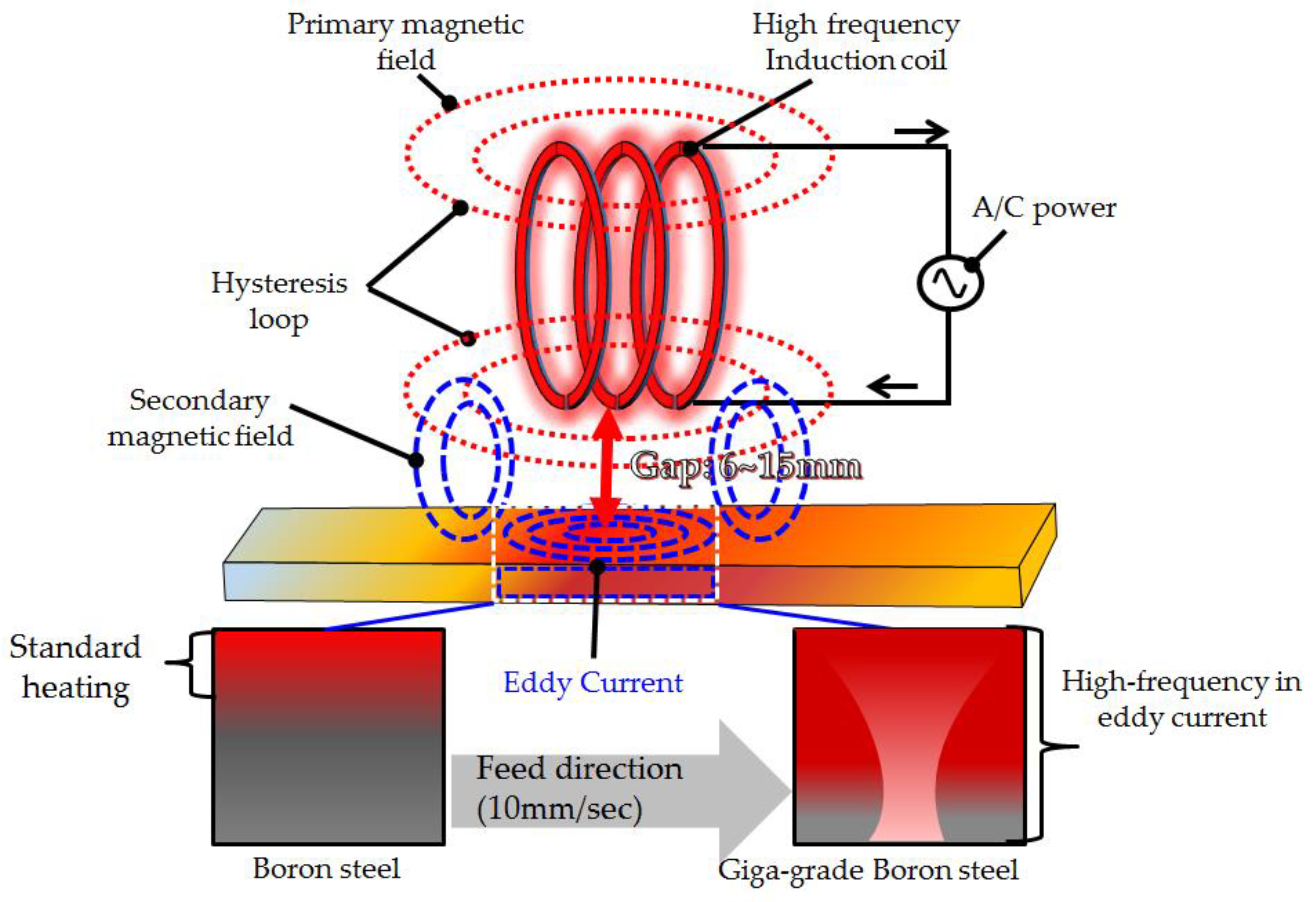
Figure 1 shows the structure of high-frequency induction heating by eddy currents. The eddy current heating method by high-frequency induction heating was used. When the high-frequency induction coil was moved to the specimen to be heated and the high-frequency AC flowed in the coil, the high-frequency primary magnetic field was generated. The direction of the high-frequency magnetic flux drew the hysteresis loop and penetrated the specimen through the secondary magnetic field. The current, which is referred to as an eddy current, was generated in the specimen by the magnetic field, and the temperature of the specimen increased due to heating. The boron steel material forms an austenite structure on ferrite and pearlite phases when heated at a temperature higher than 900 °C [
7]. Due to the phase transformation of martensite after the high-frequency induction heating process, the tensile strength increases to 1500 MPa, and the elongation decreases to 5% [
5].
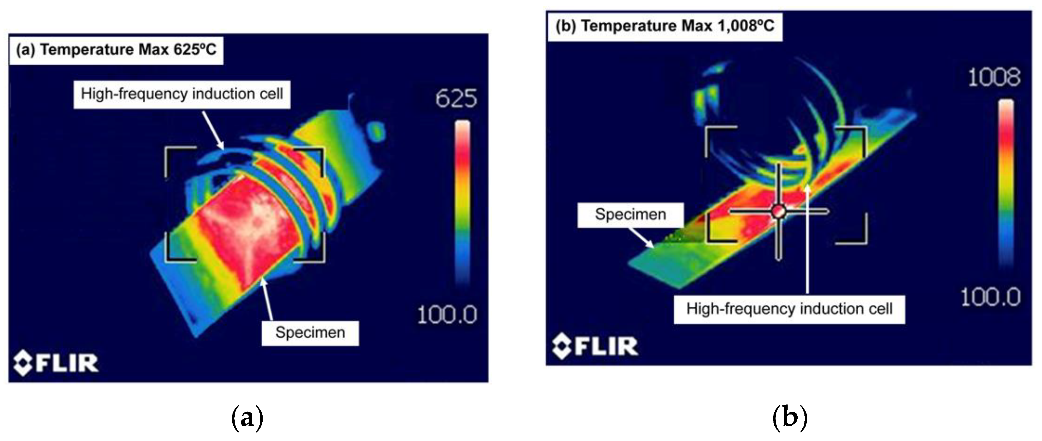
Figure 2 shows the heat treatment results of the transverse heating (TH) and LH methods, which were applied using the maximum high-frequency induction heating power of 30 kW. In
Figure 2(a), the heated object is located inside the high-frequency induction coil. This method is mostly applied to pipe-shaped specimens. In
Figure 2(b), the high-frequency induction heating coil is located outside the specimen. Depending on the high-frequency induction heating coil method, the heating temperature applied from the outside reached a minimum of 625 °C and a maximum of 1008 °C. This confirmed that heating outside the coil produced a higher maximum temperature than heating inside the coil under the same coil power conditions. The LH method exhibited higher heat treatment efficiency because the secondary magnetic field of the high-frequency AC was affected locally. Therefore, the role of the high-frequency induction heating coil was very important depending on the penetration depth (δ), specimen thickness (t), and length (d). The maximum strength is achieved after quenching from above Ac3, which was not necessarily from higher than 900 °C [
16]. This indicates that the LH method can achieve excellent local heat treatment in the high-frequency induction heating process.
3. Experimental Procedure
In this study, boron steel coated with Al–Si, which is typically applied to commercial automobiles, was used. The test specimen size of the plate was 100 mm in length, 200 mm in width, and 100 mm in thickness.
Table 1 shows the chemical composition of the material. Boron effectively improves the hardenability of steel, even when a trace of several tens of ppm is added; thus, studies have long been conducted to replace costly hardenability elements, such as Ni, Cr, and Mo, with boron [
17]. Although various mechanisms for hardenability improvement by boron addition have been proposed, boron is segregated in the austenite grain boundary and reduces the energy of the grain boundary [
18]. However, it would not actually be a hardenability loose effect, but rather a reduction of the effectiveness of boron, because its solid solubility in steel is low, and it easily forms precipitates (e.g., AlN, BN, and M23(C,B)6) in the grain boundary depending on the alloying elements or the heat treatment conditions [
7].
Table 2 shows the mechanical properties of boron steel before and after heat treatment. As the hardenability of steel is significantly improved when boron is added (0.001–0.003 wt%), the alloying elements and heat treatment conditions are very important to obtain the maximum hardenability.
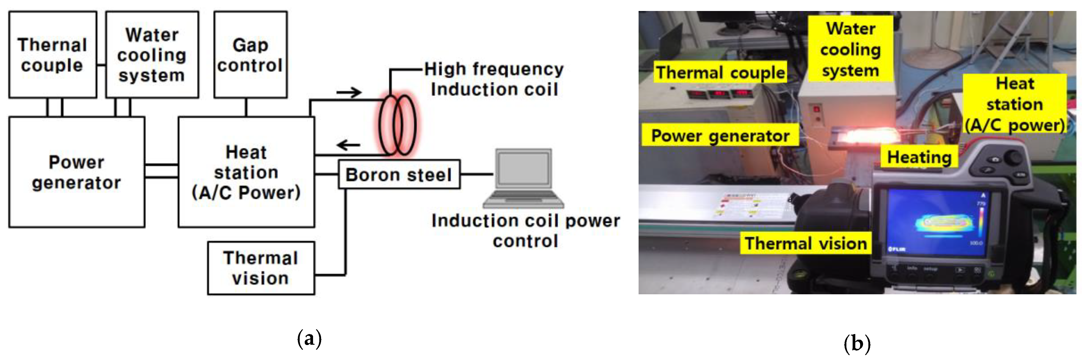
Figure 3 shows the experimental setup for the high-frequency induction heating LH method, which uses eddy currents. The high-frequency induction heater (PSIH series, PSTEK Corp., Gunpo- Gyeonggi, Korea) used the 380-V 3Φ power supply; the coil power was from 15 to 30 kW, and the maximum travel speed was 30 mm per minute. System integration was performed using a jig, an induction coil, a specimen temperature measurement device (thermal imaging cameras and thermocouples were measured in the central area of the specimen), and a cooling device. The system was heated to the target temperature in the fixed state; then, transport and continuous water quenching were applied.
Table 3 shows the experimental conditions for high-frequency induction heating, which affects the maximum heat transfer depending on the coil power. Boron steel reaches its maximum strength after quenching from above Ac3, which is not necessarily from higher than 900 °C [
10]. Therefore, the high-frequency induction heating coil power was varied from 15 to 30 kW in 3–kW intervals, and the gap between the heating coil and the boron steel specimen was set to between 6–15 mm to prevent short circuits and burnouts.
Figure 4(a) shows the specimen for the tensile test, which was performed by processing a specimen subjected to high-frequency induction heating using a waterjet (SJA-1224, Tops Corp., Siheung-Gyeonggi, Korea) for standard specimen production. The tensile strength was measured using a tensile tester (ESM 1500, Exstec Corp., Bucheon-Gyeonggi, Korea) at 5 mm/min in accordance with ASTM E8.
Figure 4(b) shows the measurement positions in the hardness test. The hardness was measured using a micro-Vickers hardness tester (Tukon 2100 series, Wolpert Corp., City, State Abbreviation, USA). A 98-N load was applied to the specimen. The hardness was measured at 10 points located on the left and right sides of the center at 1-mm intervals.
To analyze the microstructures of the parts fabricated by each high-frequency induction heating power, a scanning electron microscope (S-4800, Hitachi Corp., City, Japan) was used. Specimens were prepared by processing the plates subjected to high-frequency induction heating into the size of 10 mm × 10 mm. The specimens were observed after polishing with 1-μm diamond paste.
4. Results and Discussion
4.1. Temperature Characteristics of the LH Method
The main variables that can be adjusted in the high-frequency induction heater are the coil power and the distance between the coil and the mean values of three specimens (r). The tensile strength obtained depends on the heat treatment of boron steel; temperatures of 900 °C or higher are required to reach the maximum strength after quenching from above Ac3, which is not necessarily from higher than 900 °C [
10].
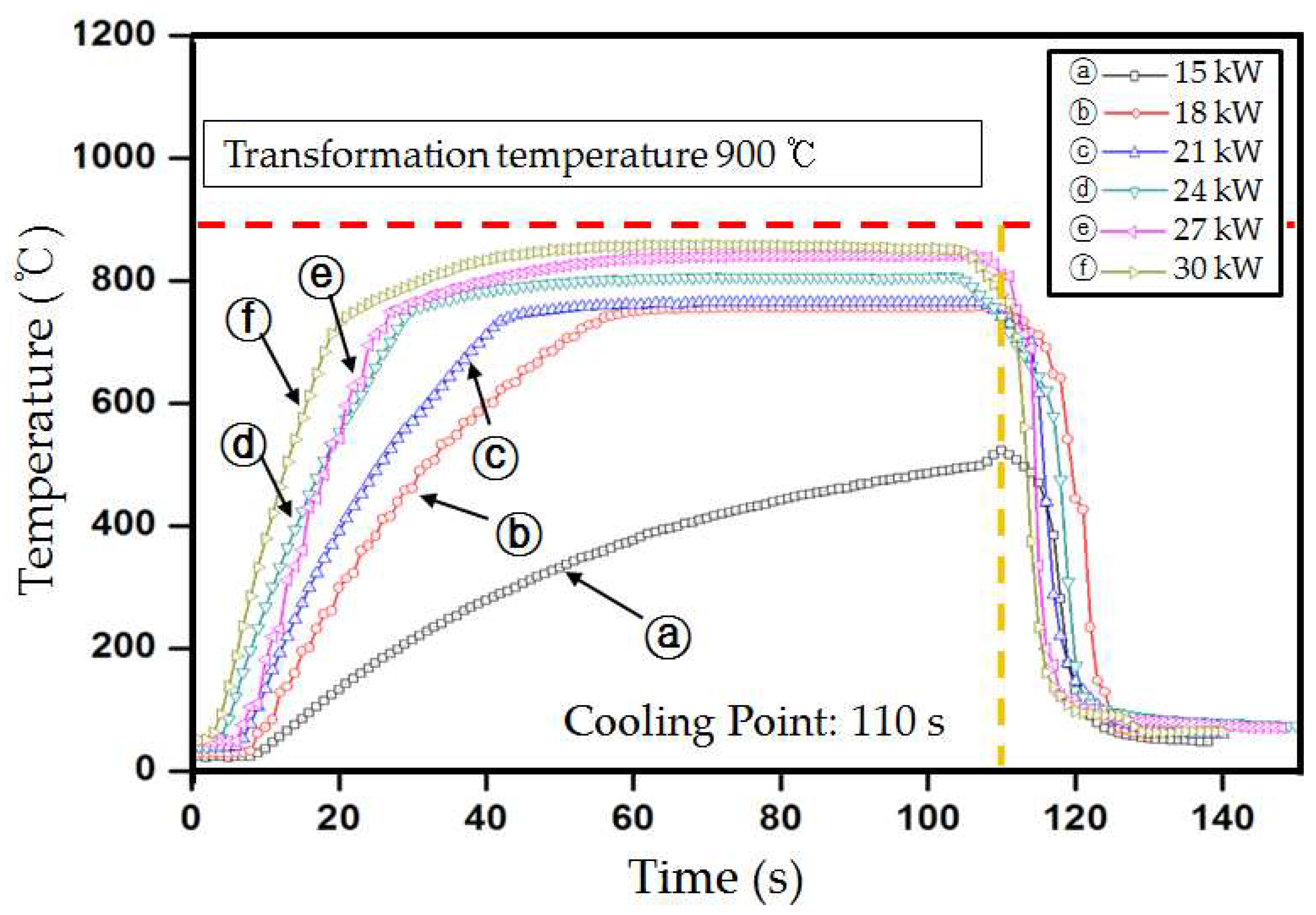
Figure 5 shows the results obtained when the coil power was increased from 15 kW to the maximum output of 30 kW in 3-kW intervals, while the distance between the boron steel specimen and the fixed position of the coil was stopped at 15 mm. The temperature increased after 20 s, except for at a coil power of 15 kW, and converged to a certain value before 50 s in all the cases. However, the target temperature of 900 °C could not be reached.
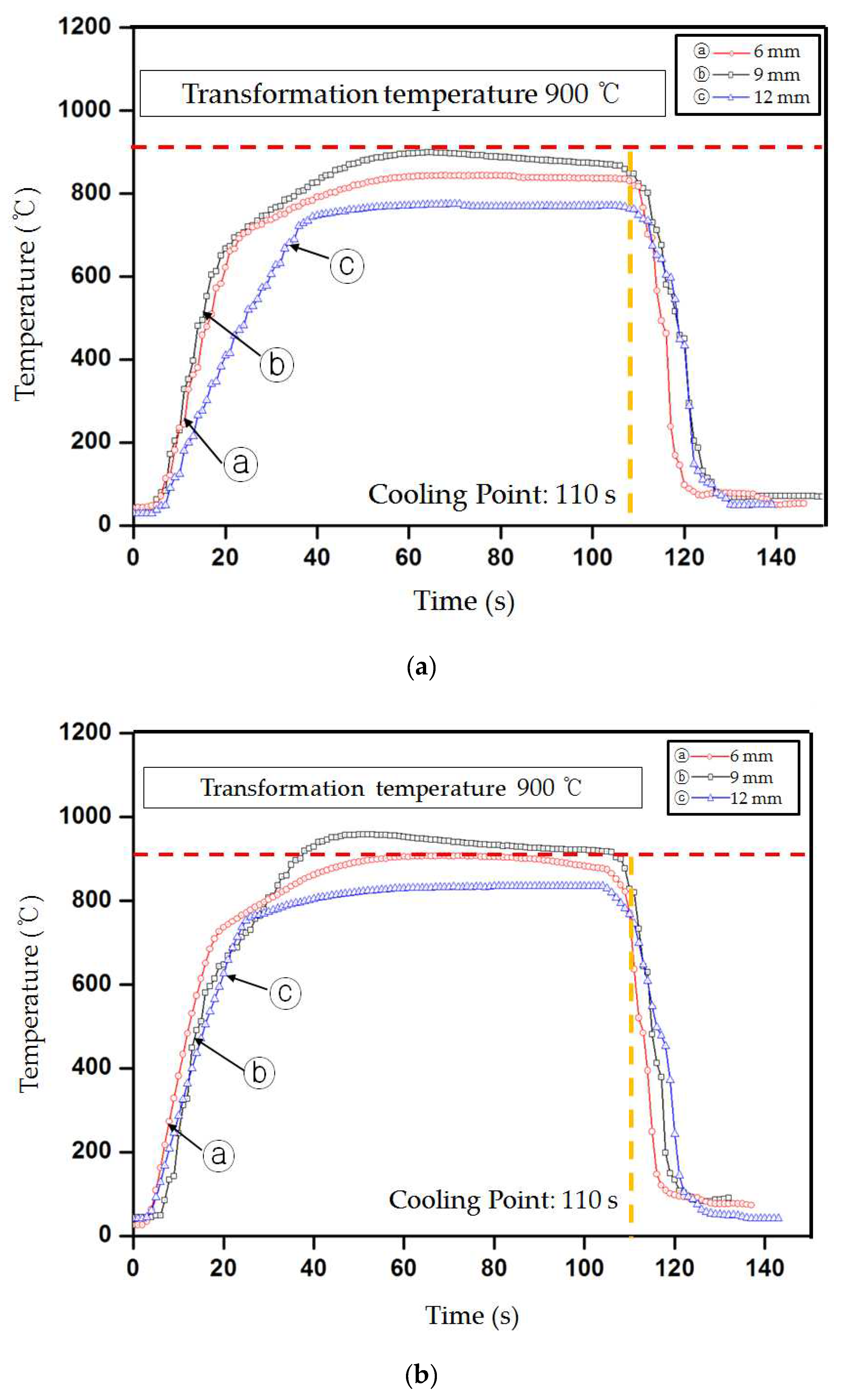
Figure 6 shows the results of the temperature measurements at coil powers of 21 and 24 kW and distances of 6, 9, and 12 mm. As the distance decreased, the temperature became closer to the target value. As displayed in
Figure 6(a), the average temperatures were 898, 843, and 775 °C at the distances of 6, 9, and 12 mm, respectively, under a coil power of 21 kW. In
Figure 6(b), the average temperatures are 952, 907, and 835 °C at the distances of 6, 9, and 12 mm, respectively, under a coil power of 24 kW. The target temperature of 900 °C was maintained at a coil power of 24 kW and distance of 6 or 9 mm. As a result, as the distance decreased, the temperature became closer to the target value.
4.2. Evaluation of Mechanical Properties
To evaluate the mechanical properties of boron steel hardened by the LH method, the tensile strength and hardness were analyzed at different values of coil power.
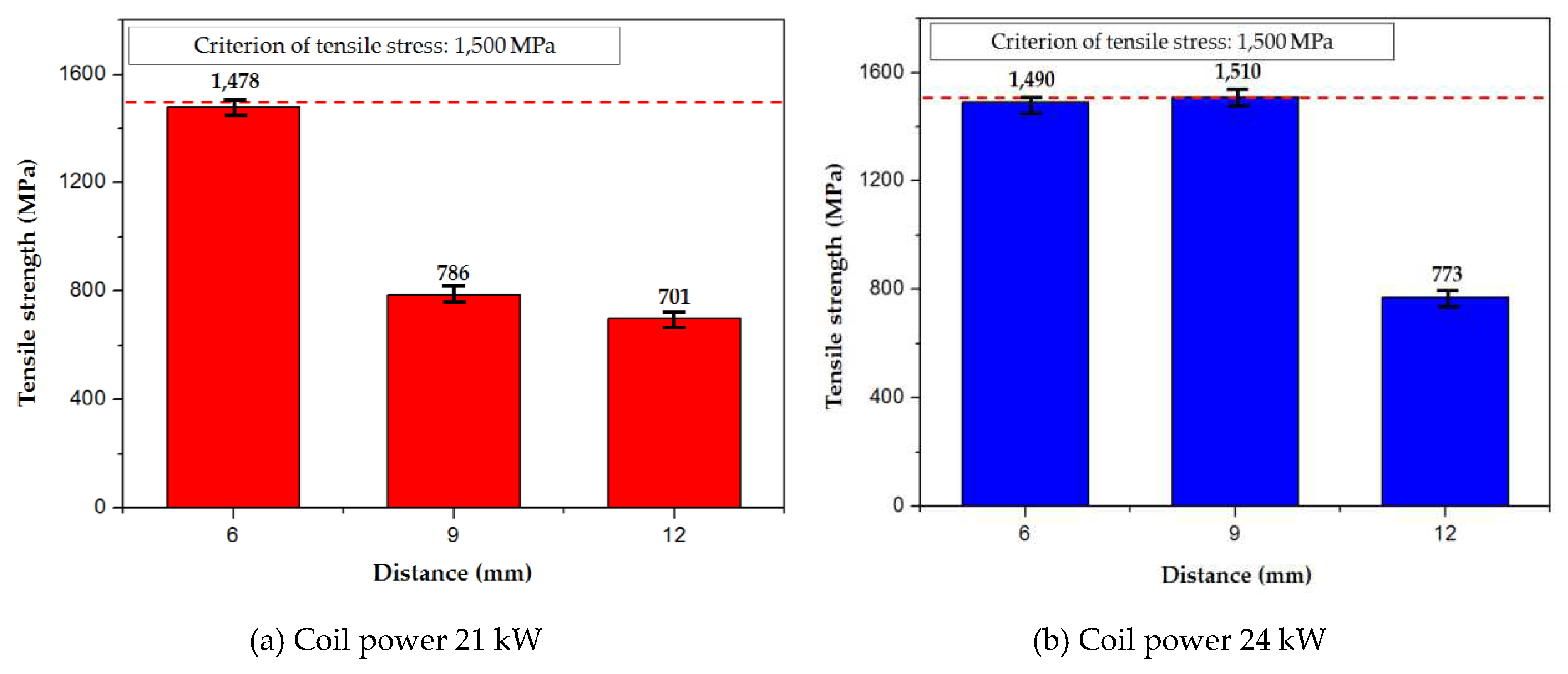
Figure 7 shows the change in tensile strength with the high-frequency induction heating condition and the distance from the mean values of three specimens. As shown in
Figure 7(a), an average tensile strength of 1478 MPa was measured when the coil power was 21 kW and the distance from the specimen was 6 mm. In
Figure 7(b), the average tensile strength values of 1490 and 1510 MPa were measured at the distances of 6 and 9 mm, respectively, under a coil power of 24 kW. The tensile strength increased as the coil power increased and the distance from the specimen decreased. However, as the distance from the specimen decreases further, burnout may occur on the surface or inside the boron steel, which can affect its strength. Therefore, it is necessary to maintain appropriate values of coil power and distance from the boron steel specimen.
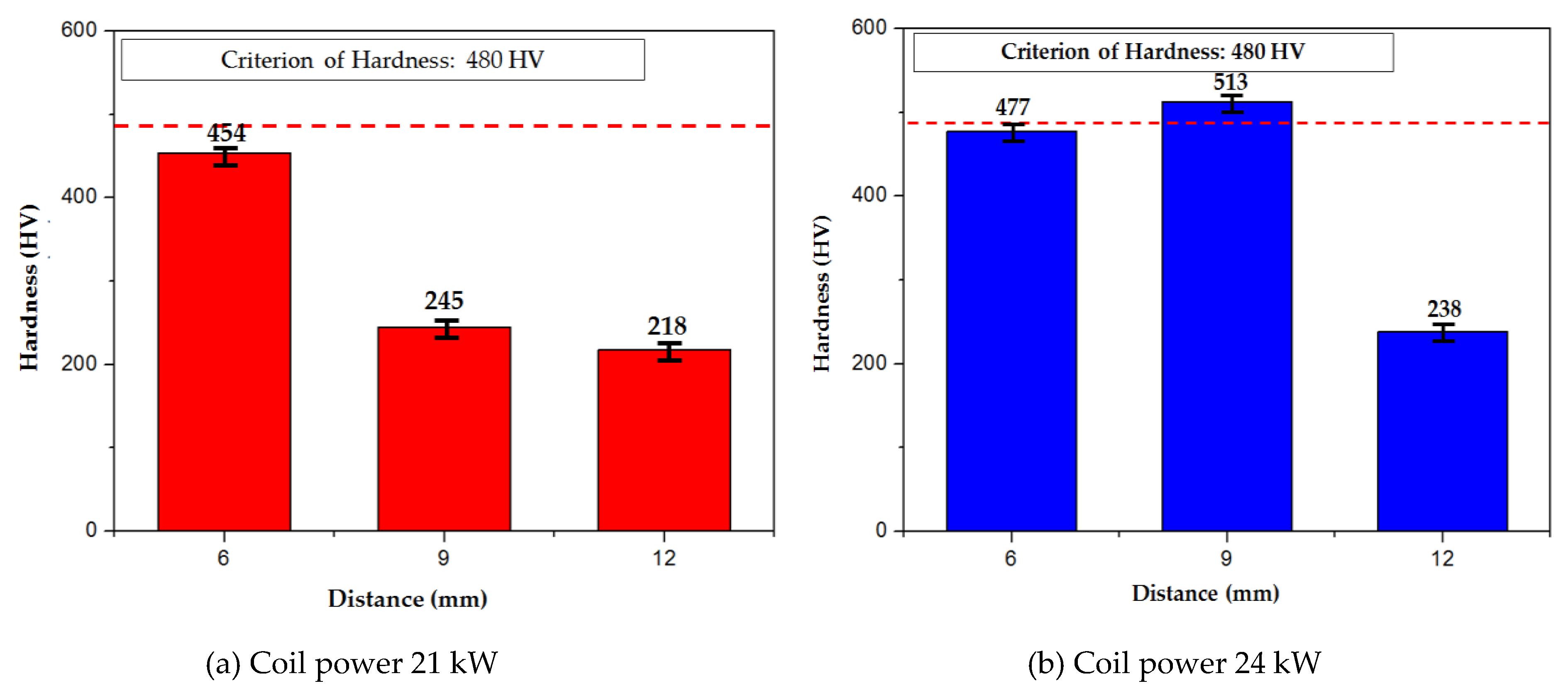
Figure 8 shows how the hardness values varied with the coil power and distance from the specimen. To examine the hardness of the mean values of three specimens, the hardness value at the thermocouple installation position was measured using a Vickers hardness tester after setting it to 1 Hv (1 kg). The hardness increased as the tensile strength increased. A tensile strength of 1500 MPa or higher and a hardness of 500 Hv or higher could be secured when the coil power was 24 kW and the distance from the specimen was 9 mm.
4.3. Microstructural Analysis
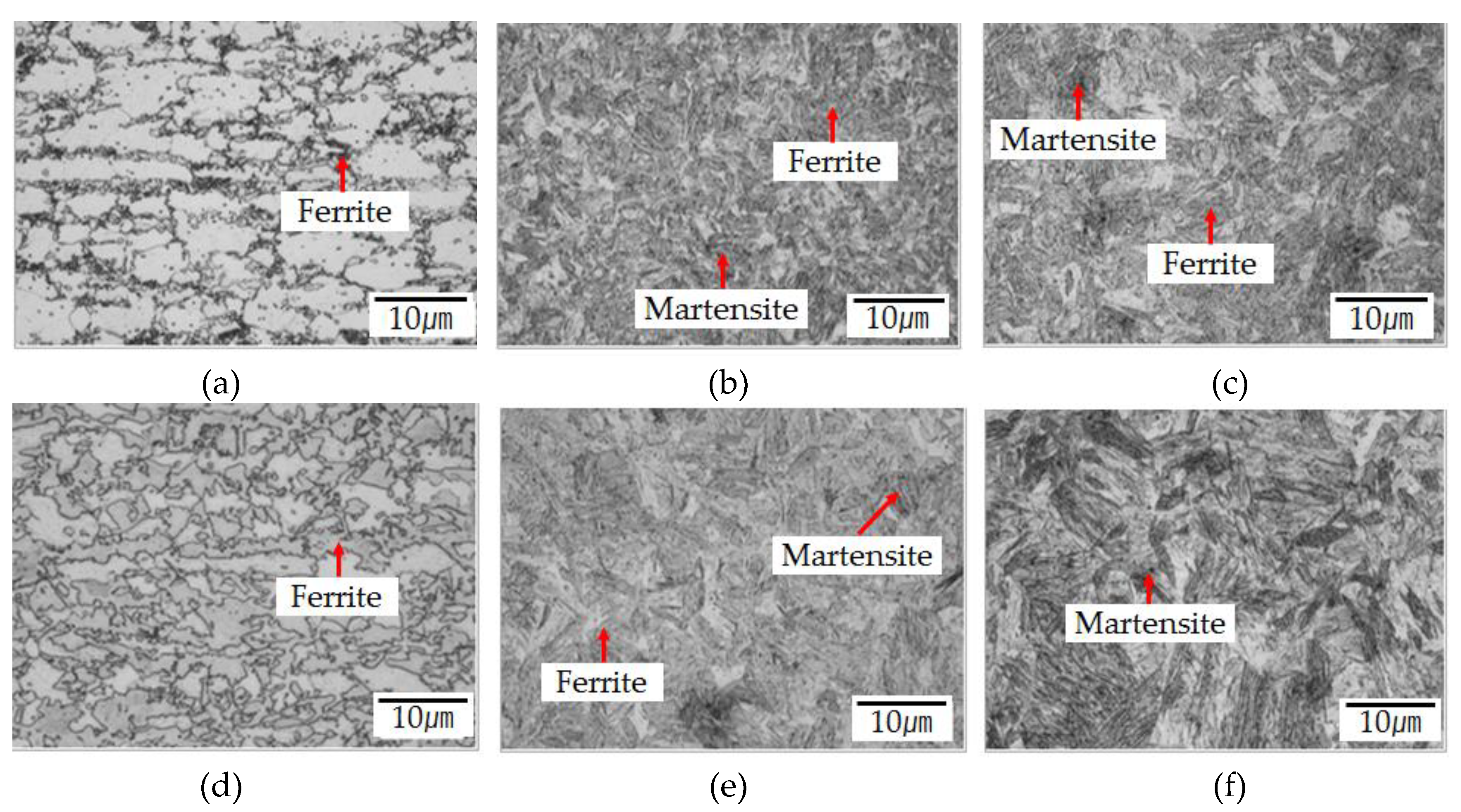
Figure 9 shows the phase composition of the structures after high-frequency induction heating in the specimen center. The formation of austenite and a small amount of ferrite was confirmed when the high-frequency induction heating coil power was 21 kW and the distance from the boron steel specimen was 12 mm in
Figure 9(a). As the coil power increased, the grain size decreased in austenite and ferrite structures. When the coil power was 21 kW and the distance from the specimen was 6 mm, a martensite structure was formed in
Figure 9(b,c).
Figure 9 (d–f) shows that martensite could also be observed when the distance from the specimen was 6 or 9 mm at a coil power of 24 kW. The structural analysis results revealed that austenite and ferrite structures appeared as the coil power increased and transformed into the martensite structure at the highest temperature. The maximum tensile strength could be obtained depending on the coil power and the distance between the coil and the specimen, which were the control variables of high-frequency induction heat treatment. The coil power of 24 kW or higher and the distance from the boron steel specimen of 9 mm would be appropriate to meet the tensile strength of 1500 MPa or higher and a hardness of Hv 500 or higher, which were the target values determined from the experimental conditions.
5. Conclusions
In this study, the surface temperature variations of boron steel specimens were investigated at different values of coil power and distance from the specimen during longitudinal heating (LH), which is a high-frequency induction heating method that uses eddy currents. The following results were obtained by evaluating the mechanical properties and the microstructural evolution.
When the high-frequency induction heating coil power was between 15–30 kW and the distance from the specimen was 15 mm, the boron steel material could not reach the target temperature of 900 °C.
When the high-frequency induction coil power was 21 kW and the distance from the boron steel specimen was 6 mm, a tensile strength of 1478 MPa was obtained when the surface temperature was 898 °C. When the coil power was 24 kW or higher and the distance from the specimen was 9 mm, a tensile strength of 1510 MPa could be obtained.
The hardness of the boron steel ranged from 218 to 513 Hv depending on the coil power and the distance from the specimen. The hardness increased as the coil power increased. However, it decreased to 477 Hv when the coil power was 24 kW and the distance from the specimen was 6 mm. Low hardness was a result of local melting of the boron steel, causing burnout.
The microstructure was transformed into the martensite structure when the coil power was 21 kW and the distance from the specimen was 6 mm. The transformation into the martensite structure was also be confirmed when the distance from the specimen was 6 or 9 mm at the coil power of 24 kW. Through the heat treatment for the coil power and the distance from the specimen, their correlations with the maximum tensile strength were determined.
Author Contributions
For research articles with several authors, a short paragraph specifying their individual contributions must be provided. The following statements should be used “conceptualization, X.X. and Y.Y.; methodology, X.X.; software, X.X.; validation, X.X., Y.Y. and Z.Z.; formal analysis, X.X.; investigation, X.X.; resources, X.X.; data curation, X.X.; writing—original draft preparation, X.X.; writing—review and editing, X.X.; visualization, X.X.; supervision, X.X.; project administration, X.X.; funding acquisition, Y.Y.”, please turn to the CRediT taxonomy for the term explanation. Authorship must be limited to those who have contributed substantially to the work reported.
Funding
Please add: “This research received no external funding” or “This research was funded by NAME OF FUNDER, grant number XXX” and “The APC was funded by XXX”. Check carefully that the details given are accurate and use the standard spelling of funding agency names at
https://search.crossref.org/funding, any errors may affect your future funding.
Acknowledgments
In this section you can acknowledge any support given which is not covered by the author contribution or funding sections. This may include administrative and technical support, or donations in kind (e.g., materials used for experiments).
Conflicts of Interest
Declare conflicts of interest or state “The authors declare no conflict of interest.” Authors must identify and declare any personal circumstances or interest that may be perceived as inappropriately influencing the representation or interpretation of reported research results. Any role of the funders in the design of the study; in the collection, analyses or interpretation of data; in the writing of the manuscript, or in the decision to publish the results must be declared in this section. If there is no role, please state “The funders had no role in the design of the study; in the collection, analyses, or interpretation of data; in the writing of the manuscript, or in the decision to publish the results”.
References
- Yang, Z.; Mehdi, N.; Omer, T. Vehicle to grid regulation services of electric delivery trucks: Economic and environmental benefit analysis. Appl. Energy 2016, 15, 161–175. [Google Scholar]
- Mega, T.; Hasegawa, K.; Kawabe, H. Ultra high-strength steel sheets for bodies, reinforcement parts, and seat frame parts of automobile. JFE Tech. Rep. 2014, 4, 38–43. [Google Scholar]
- Adrian, W. Vehicle weight is the key driver for automotive composites. Reinf. Plast. 2017, 61, 100–102. [Google Scholar]
- Matsuoka, S.; Hasegawa, K.; Tanaka, Y. Newly-developed ultra-high tensile strength steels with excellent formability and weldability. JFE Tech. Rep. 2007, 10, 13–18. [Google Scholar]
- Kim, K.Y.; Choy, L.J.; Shin, H.I.; Cho, J.H.; Lee, C.H.; Kang, M.C. Characteristics of mechanical procerties and micro structure according to high-frequency induction heating conditions in rol forming process of a sill side part. J. Korean Soc. Manuf. Process Eng. 2017, 16, 87–94. [Google Scholar]
- Karbasian, H.; Tekkaya, A.E. A review on hot stamping. J. Mater. Process. Technol. 2010, 210, 2103–2118. [Google Scholar] [CrossRef]
- Zhu, L. J.; Gu, Z. W.; Xu, H.; Lü, Y.; Chao, J. Modeling of microstructure evolution in 22MnB5 steel during hot stamping. J. Iron Steel Res. Int. 2014, 21, 197–201. [Google Scholar] [CrossRef]
- Hyun, C.M.; Yi, M.S.; Cho, S.H.; Jang, T.W. A study on the mechanical properties of heated plates by induction heating system. Korean Weld. Join. Soc. 2014, 32, 47–51. [Google Scholar]
- Kolleck, R.; Veit, R.; Merklein, M.; Lechler, J.; Geiger, M. Investigation on induction heating for hot stamping of boron alloyed steels. CIRP Annals 2009, 58, 275–278. [Google Scholar] [CrossRef]
- Tohru, Y.; Eiji, I.; Koichi, S.; Koji, H. Springback problems in forming of high-strength steel sheets and countermeasures. Nippon Steel Tech. Rep. 2013, 103, 4–10. [Google Scholar]
- Merklein, M.; Wieland, M.; Lechner, M.; Bruschi, S.; Ghiotti, A. Hot stamping of boron steel sheets with tailored properties: A review. J. Mater. Process. Technol. 2016, 228, 11–24. [Google Scholar] [CrossRef]
- Sul, Y.T.; Lee, E.Y.; Kwon, H.M. Development of induction heating superheater system using new heat exchanging method. J. Korea Acad.-Ind. Coop. Soc. 2009, 10, 740–746. [Google Scholar]
- Yanhong, M.; Baoyu, W.; Jing, Z.; Xu, H.; Xuetao, L. Hot stamping of boron steel using partition heating for tailored properties: Experimental trials and numerical analysis. Metall. Mater Trans. A 2017, 48, 5467–5479. [Google Scholar]
- Yao, S.J.; Fenga, L.; Yang, D.L.; Han, D.X.; Liua, Y.; Lia, Q.Q.; Guo, J.H.; Chao, B.J. A potential hot stamping process for microstructure optimization of 22MnB5 steels characterized by asymmetric pre-rolling and one- or two-step pre-heating. J. Mater. Process. Technol. 2018, 254, 100–107. [Google Scholar] [CrossRef]
- Gui, Z.; Liang, W.; Liu, Y.; Zhang, Y. Thermo-mechanical behavior of the Al–Si alloy coated hot stamping boron steel. Mater. Des. 2014, 60, 26–33. [Google Scholar] [CrossRef]
- Somunkiran, I.; Buytoz, S.; Dagdelen, F. Determination of curie temperatures and thermal oxidation behavior of Fe-Cr matrix composites produced by hot pressing. J. Alloy. Compd 2019, 777, 302–308. [Google Scholar] [CrossRef]
- Zhu, L.-J.; Gu, Z.-W.; Xu, H.; Lü, T.; Chao, J. Modeling of microstructure evolution in 22MnB5 steel during hot stamping. J. Iron Steel Res. Int. 2014, 21, 197–201. [Google Scholar] [CrossRef]
- Merklein, M.; Lechler, J.; Geiger, M. Characterisation of the flow properties of the quenchenable ultra high strength steel 22MnB5. CIRP Ann. 2006, 55, 229–232. [Google Scholar] [CrossRef]
Figure 1.
Schematic process drawings of the eddy-current method, which is a high-frequency induction heating method.
Figure 1.
Schematic process drawings of the eddy-current method, which is a high-frequency induction heating method.
Figure 2.
Photo of high-frequency induction heating coil methods: (a) transverse heating method and (b) longitudinal heating method.
Figure 2.
Photo of high-frequency induction heating coil methods: (a) transverse heating method and (b) longitudinal heating method.
Figure 3.
High-frequency induction heating system: (a) schematic diagram of high-frequency induction heating equipment; (b) experimental setup of high-frequency induction heating.
Figure 3.
High-frequency induction heating system: (a) schematic diagram of high-frequency induction heating equipment; (b) experimental setup of high-frequency induction heating.
Figure 4.
Specimen configuration of tensile strength test and micro-Vickers hardness. (a) Schematic diagram of specimen for the tensile test; (b) schematic diagram of specimen for micro-Vickers hardness.
Figure 4.
Specimen configuration of tensile strength test and micro-Vickers hardness. (a) Schematic diagram of specimen for the tensile test; (b) schematic diagram of specimen for micro-Vickers hardness.
Figure 5.
Temperature variations with the high-frequency coil power.
Figure 5.
Temperature variations with the high-frequency coil power.
Figure 6.
Figure 6. Temperature variations with the distance from the specimen at the coil power of 21 and 24 kW: (a) coil power: 21 kW, distance: 6, 9, and 12 mm; (b) coil power: 24 kW, distance: 6, 9, and 12 mm.
Figure 6.
Figure 6. Temperature variations with the distance from the specimen at the coil power of 21 and 24 kW: (a) coil power: 21 kW, distance: 6, 9, and 12 mm; (b) coil power: 24 kW, distance: 6, 9, and 12 mm.
Figure 7.
The change in tensile strength with the distance from the specimen at the coil powers of 21 and 24 kW; (a) coil power: 21 kW, distance: 6, 9, and 12 mm; (b) coil power: 24 kW, distance: 6, 9, and 12 mm.
Figure 7.
The change in tensile strength with the distance from the specimen at the coil powers of 21 and 24 kW; (a) coil power: 21 kW, distance: 6, 9, and 12 mm; (b) coil power: 24 kW, distance: 6, 9, and 12 mm.
Figure 8.
Figure 8. The change in hardness with the distance from the specimen at the coil power of 21 and 24 kW; (a) coil power: 21 kW, distance: 6, 9, and 12 mm (b) coil power: 24 kW, distance: 6, 9, and 12 mm
Figure 8.
Figure 8. The change in hardness with the distance from the specimen at the coil power of 21 and 24 kW; (a) coil power: 21 kW, distance: 6, 9, and 12 mm (b) coil power: 24 kW, distance: 6, 9, and 12 mm
Figure 9.
Temperature increase at different high-frequency coil power values. (a) 21 kW, 12 mm; (b) 1 kW, 9 mm; (c) 21 kW, 6 mm; (d) 24 kW, 12 mm; (e) 24 kW, 9 mm; (f) 24 kW, 6 mm.
Figure 9.
Temperature increase at different high-frequency coil power values. (a) 21 kW, 12 mm; (b) 1 kW, 9 mm; (c) 21 kW, 6 mm; (d) 24 kW, 12 mm; (e) 24 kW, 9 mm; (f) 24 kW, 6 mm.
Table 1.
Chemical composition of boron steel.
Table 1.
Chemical composition of boron steel.
| Material |
C |
Si |
Mn |
P |
S |
Cr |
B |
| wt (%) |
0.2 |
0.21 |
1.27 |
0.017 |
0.017 |
0.22 |
0.028 |
Table 2.
Mechanical properties of boron steel.
Table 2.
Mechanical properties of boron steel.
| Properties |
As delivered |
Hardened |
| Yield strength (MPa) |
457 |
1010 |
| Tensile strength (MPa) |
608 |
1500 |
| Elongation (%) |
10 |
6 |
| Vickers hardness (Hv) |
220 |
480 |
Table 3.
Conditions of high-frequency induction heating.
Table 3.
Conditions of high-frequency induction heating.
| Coil Power (kW) |
15, 18, 21, 24, 27, 30 |
|
Frequency(kHz)
|
30–40 |
| Distance (mm) |
6 |
9 |
12 |
15 |
|
Disclaimer/Publisher’s Note: The statements, opinions and data contained in all publications are solely those of the individual author(s) and contributor(s) and not of MDPI and/or the editor(s). MDPI and/or the editor(s) disclaim responsibility for any injury to people or property resulting from any ideas, methods, instructions or products referred to in the content. |
© 2023 by the authors. Licensee MDPI, Basel, Switzerland. This article is an open access article distributed under the terms and conditions of the Creative Commons Attribution (CC BY) license (http://creativecommons.org/licenses/by/4.0/).
