Submitted:
30 August 2023
Posted:
01 September 2023
You are already at the latest version
Abstract
In this paper, the distributed formation tracking control problem of quadrotor unmanned aerial vehicles (UAVs) is considered. Adaptive backstepping technology is used to design flight control schemes for quadrotor UAVs. For the position subsystem, a distributed robust formation tracking control scheme is developed to achieve formation flight of quadrotor UAVs and track the desired flight trajectory. For the attitude subsystem, an adaptive disturbance rejection control scheme is proposed to achieve attitude stabilization during UAV flight under uncertain disturbances. Compared with the existing results, the novelty of this paper is that the proposed formation control scheme does not require the use of the quadrotor model parameters. Finally, a quadrotor UAV swarm system is used to verify the effectiveness of the proposed control scheme.
Keywords:
unmanned aerial vehicles (UAV)
; formation tracking control
; disturbance rejection
; unknown parameters
1. Introduction
In recent years, cooperative control of quadrotor unmanned aerial vehicles (UAVs) has received considerable attention due to its broad applications in areas such as wireless communication, nuclear radiation detection, and agricultural mapping. Formation control is one of the most important research areas in the field of cooperative control for quadrotor UAVs. A formation composed of multiple low-cost UAVs can replace an expensive multi-functional UAV to complete complex tasks. In addition, UAV formations can provide system redundancy and reconfiguration ability [1]. Formation control of quadrotor UAVs has garnered significant research attention owing to its prospective applications in both military and civilian domains [2,3,4]. From the perspective of control mechanisms, the existing methods of quadrotor UAV formation control include leader-follower method [5], artificial potential method [6], behavior-based method [7], etc. Recently, the work in [8] studied dynamic formation collision avoidance control for quadrotor UAVs using the virtual structure method. In [9], a consensus-based method was used to design a time-varying formation tracking control scheme for quadrotor UAVs. However, the quadrotor UAV model considered in the above literature is simplified, and the designed formation control schemes rely on the model parameters of the quadrotor UAV. In many practical applications of quadrotor UAVs, it can be difficult to accurately obtain model parameters. As a result, it is important to design a formation control scheme for quadrotor UAVs that does not rely on the use of model parameters. In addition, quadrotor UAVs are very sensitive to uncertain disturbances, and it is necessary to design effective disturbance rejection flight control schemes. The disturbance rejection control of individual UAVs has been extensively studied in the existing literature [10,11,12,13,14,15]. For quadrotor UAV swarms, uncertain disturbances acting on each UAV will affect neighboring UAVs through the communication network. Hence, designing disturbance rejection control schemes for quadrotor UAV swarms is a more complex task. The existing literature has not extensively investigated the problem of disturbance rejection control for quadrotor UAV swarms, which underscores the significance of the research presented in this paper.
In this paper, a distributed robust formation tracking control method is proposed for quadrotor UAVs with unknown parameters and uncertain disturbances. The proposed method has the following novelties. First, a more practical formation tracking control method is proposed in this paper, which does not need to use the model parameters of the quadrotor UAV. Second, an adaptive disturbance rejection control scheme for quadrotor UAV swarms is developed. In the presence of uncertain disturbances, this scheme can still achieve formation tracking control for quadrotor UAV swarms, and the tracking error can eventually converge to zero.
The structure of this paper is arranged in the following manner. In Section II and Section III, a distributed formation tracking control scheme and an adaptive disturbance rejection attitude control method are designed for quadrotor UAVs. The efficacy of the proposed control method is validated in Section IV. Finally, Section V concludes the paper.
2. Distributed Robust Formation Tracking Control for Quadrotor UAVs
In this section, a distributed formation flight control method is developed for quadrotor UAVs to achieve the following three control objectives: 1) form the desired formation; 2) track the desired flight trajectory; 3) reduce the influence of uncertain disturbances.
2.1. Graph Theory
The communication topology among a group of N quadrotor UAVs is considered as an undirected graph , where denotes the vertex set and denotes the edge set. The neighbor set of the ith UAV is : there is a communication link between UAV i and UAV j, . Define a weight for each edge , if , and otherwise. The Laplacian matrix is , where and . The leader adjacency matrix is , where if UAV i can obtain the desired flight trajectory and otherwise. An undirected graph is considered connected if there is a path between every pair of distinct vertices.
Next, two useful lemmas are introduced.
Lemma 1.
[16]. If the undirected graph is connected, and at least one UAV can obtain the desired flight trajectory, then the symmetric matrix is positive definite.
Lemma 2.
[17]. For any and , the inequality holds.
2.2. Quadrotor UAV Position Dynamic Model
In this paper, define as the attitude of the quadrotor UAV, where and denote the angles of roll, pitch and yaw, respectively. The rotation matrix that describes the transformation from the body-fixed frame to the earth-fixed frame is denoted as
where and denote sin and cos, respectively.
Define as the position of the quadrotor UAV. As described in [18], the translational dynamic equations are given as
where m is the quadrotor mass; , , are the air drag coefficients; , b is the lift coefficient and are the rotor speed; g is the acceleration of gravity.
In this paper, the formation tracking control problem of quadrotor UAVs is studied. From (2), the position dynamic system of the ith UAV can be described as
where and are the position and velocity of UAV i, respectively; are the unknown system parameters; are the control inputs, and In addition, and represent uncertain disturbances.
Assumption 1.
The uncertain disturbances satisfy
where and are unknown constants.
Definition: A time-varying formation formed by a group of N UAVs is specified by , where is the piecewise continuously formation vector. Formation tracking control of quadrotor UAVs can be achieved if
where ; and represents the desired flight trajectory.
Assumption 2.
The desired flight trajectory satisfies
where is an unknown constant.
2.3. Distributed Formation Tracking Controller Design
For the ith UAV, define two error variables
where are the virtual control functions. The detailed design procedure is given as follows:
Step 1: By defining , one can obtain , where with , , and . Then, the derivative of satisfies
The virtual control function is chosen as
where is a design constant; is the estimate of ; and is a positive continuous function satisfying , and is a positive constant. Consider the Lyapunov function
where the estimation error ; and is a design parameter.
From (9)-(11), the derivative of satisfies
The parameter update law is chosen as
Then, by applying Lemma 2, we have
Step 2: From (3) and (10), the derivative of satisfies
The formation flight controller is designed as
where is a design constant; ; and is the estimate of .
Construct the following Lyapunov function
where the estimation errors and ; and are design parameters.
From (14)-(17), the derivative of satisfies
The adaptive update laws are chosen as
Then, by applying Lemma 2, we have
Now, we present the analysis results.
Theorem 1.
Consider the quadrotor UAV swarm system (3), the formation tracking controller (16), and the adaptive laws (13) and (19). All the signals in the closed-loop system are globally bounded, and the quadrotor UAV swarm can achieve time-varying formation flying and track the virtual leader.
Integrating both sizes of (20), it follows that
From the definition of in (17), one can get that , , , , and are bounded. From (10), (16), and Lemma 1, , , and are bounded. Therefore, the boundedness of all the signals is guaranteed, and is bounded. By applying Barbalat’s lemma, one has . From the definition of and Lemma 1, it follows that formation tracking control of quadrotor UAVs can be achieved, i.e. . This completes the proof.
Remark 1.
When the distributed formation tracking controller is designed, and the desired yaw angle is treated as an additional reference signal, then the desired roll angle , the desired pitch angle , and the control input can be obtained in the following way
Since , and are continuous and bounded, it is known that and are bounded.
3. Disturbance Rejection Control of Quadrotor UAV Attitude
In this section, an adaptive disturbance rejection attitude control method will be designed for the quadrotor UAV.
3.1. Quadrotor UAV Attitude Dynamic Model
The angular velocity with respect to the attitude is given as . As described in [19], The correlation between the attitude angle and angular velocity can be denoted by
where denotes tan.
By employing the Newton-Euler formulation, the rotational dynamic equations can be derived as
where ; is the resultant torque; is the aerodynamic frictions torque; is the rotor torque; l is the distance between rotor and center of mass; d denotes the reverse moment coefficient; is the rotational inertia of each rotor; ,, are the rotary inertia; and are the drag coefficients.
Then, the following dynamic equations can be derived
where
Consider a group of N quadrotor UAVs, define , , , , , and , then the following unified attitude system can be obtained
where and represent uncertain disturbances, and
Assumption 3.
The uncertain disturbances satisfy
where and are positive constants.
Remark 2.
Note that each UAV has to estimate the desired yaw angle by the information obtained from its neighbors. Inspired by [20], design the following distributed estimator
where is an estimate of ; and are design parameters; is the signum function. From Theorem 3.1 in [19], one can get that in finite time.
3.2. Disturbance Rejection Attitude Controller Design
For the ith UAV, define two error variables
where , , and ; and are the virtual control functions. From (22) and (31), there exists an unknown constant such that . The detailed design procedure is given as follows:
Step 1: The derivative of satisfies
The virtual control function is chosen as
where is a design constant; is the estimate of . Consider the Lyapunov function
where the estimation errors ; and is a design parameter.
From (33)-(35), the derivative of satisfies
The parameter update law is chosen as
Then, by applying Lemma 2, we have
Step 2: From (29) and (32), the derivative of satisfies
The attitude controller is designed as
where is a design constant; is the estimate of ; and
Construct the following Lyapunov function
where the estimation errors and ; and are design parameters.
From (38)-(41), the derivative of satisfies
The parameter update laws are chosen as
Now, we present the analysis results.
Theorem 2.
Consider the quadrotor UAV attitude system (29), the attitude controller (40), and the adaptive laws (37) and (43). All the signals in the closed-loop system are globally bounded, and the tracking error of the attitude angle system can converge to zero.
The proof is similar to Theorem 1.
Remark 3.
The proposed distributed formation tracking control scheme does not require the use of the quadrotor model parameters. Therefore, the proposed scheme is significant for achieving distributed formation tracking control of heterogeneous quadrotor UAV swarms.
4. An Illustrative Example
In this section, we consider a swarm system consisting of five quadrotor UAVs, and the model parameters of quadrotor UAVs are borrowed from literature [18]. The communication topology among UAVs is shown in Figure 1. The desired flight trajectory are chosen as , and the desired yaw angle . The reference formation shape vectors are given by The controller parameters are chosen as , , , , , , , , , and . In addition, some uncertain disturbances are considered as and .
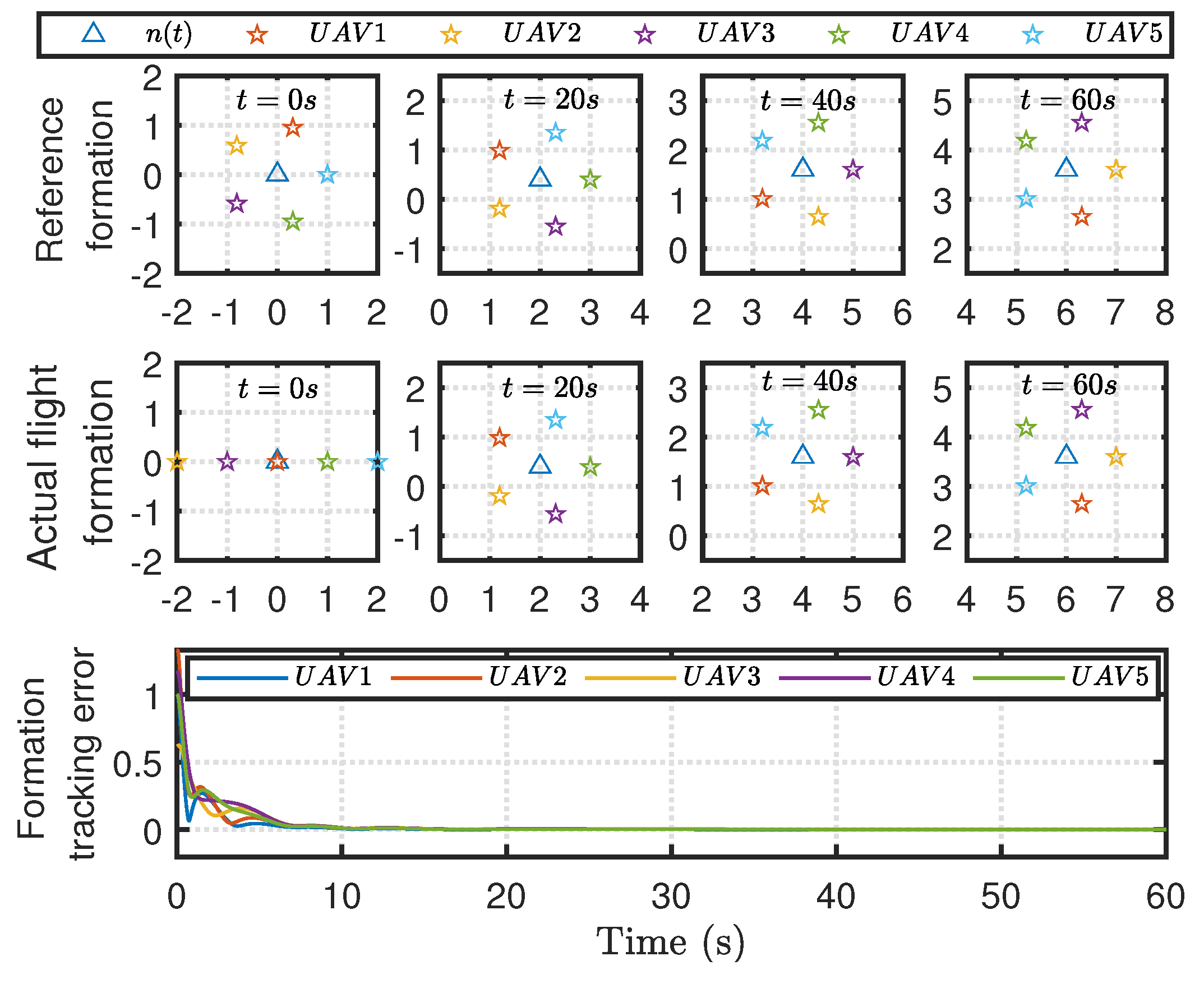
The quadrotor UAVs’ flight trajectories in the 3-D space are displayed in Figure 2. As can be seen from Figure 2, by applying the proposed control scheme, the five UAVs form a desired formation shape and track the desired flight trajectory. Figure 3 shows the reference formation shapes and the actual flight formation of quadrotor UAVs. The response curves of formation tracking errors are also shown in Figure 3. It can be seen that the formation tracking error of each UAV converges to zero.
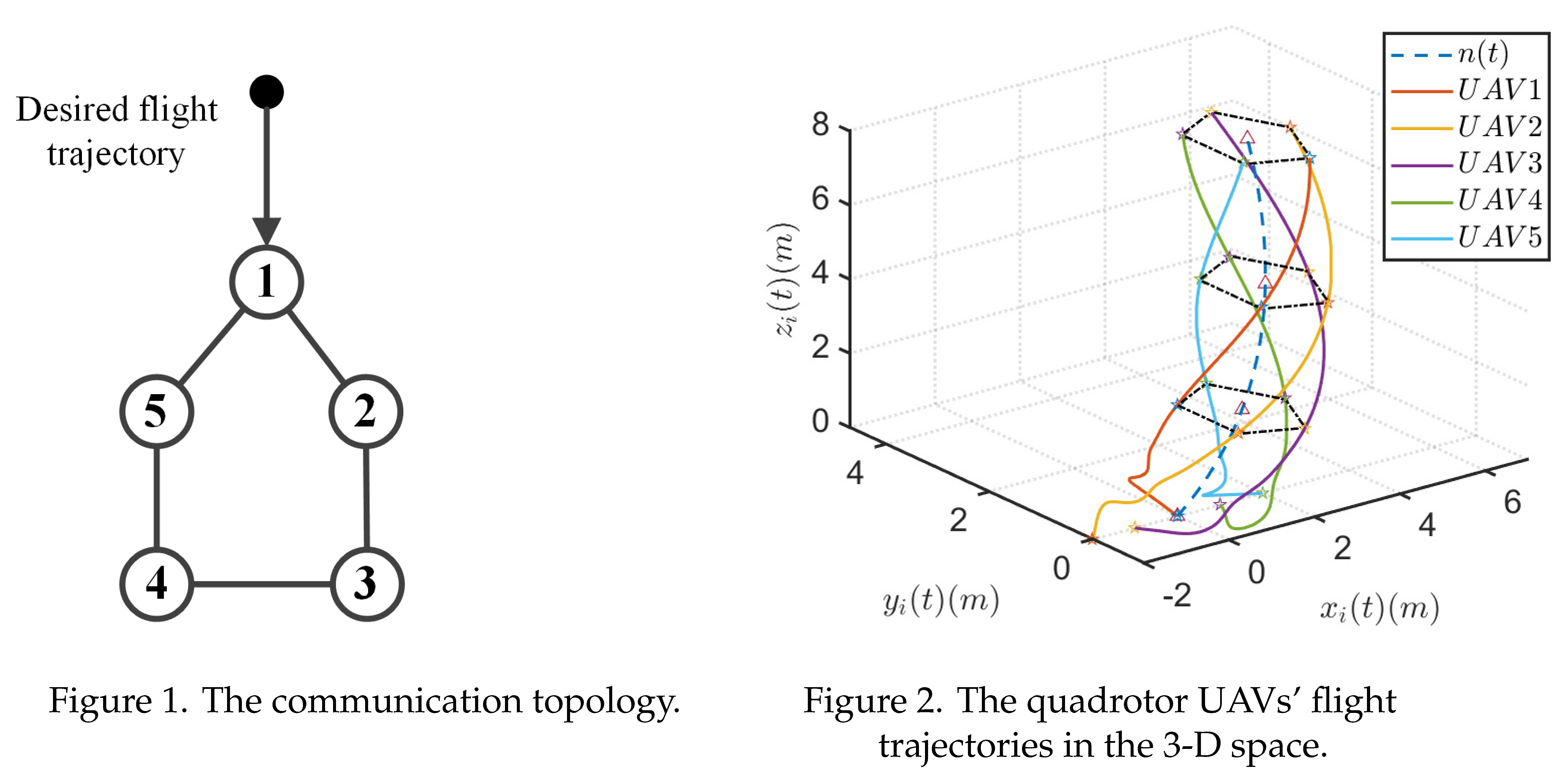
Figure 3.
Formation shapes and formation tracking errors.
5. Conclusion
In this paper, a distributed formation tracking control method has been proposed for quadrotor UAVs. The proposed control scheme does not need to use the model parameters of quadrotor UAVs, which has wider practicality. The effectiveness of the proposed method has been verified by a numerical example. Our future work includes time-varying formation tracking control of heterogeneous quadrotor UAVs under switched communication topologies.
Author Contributions
Conceptualization, L.X.X.; methodology, L.X.X.; software, L.X.X.; validation, L.X.X.; formal analysis, L.X.X.; investigation, L.X.X.; resources, L.X.X.; data curation, L.X.X.; writing—original draft preparation, L.X.X.; writing—review and editing, L.X.X.; visualization, L.X.X.; supervision, L.X.X.; project administration, L.X.X.; funding acquisition, L.X.X. All authors have read and agreed to the published version of the manuscript.
Funding
This research was funded by the National Science Foundation of China (Grant No. 62103251); and the China Postdoctoral Science Foundation (Grant No. 2021M702075).
Institutional Review Board Statement
Not applicable
Informed Consent Statement
Not applicable
Data Availability Statement
The data presented in this study are available on request from the corresponding author after obtaining permission of authorized person.
Conflicts of Interest
The authors declare no conflict of interest.
References
- Liao, F.; Teo, R.; Wang, J.L.; Dong, X.; Lin, F.; Peng, K. Distributed formation and reconfiguration control of VTOL UAVs. IEEE Transactions on Control Systems Technology 2016, 25, 270–277. [Google Scholar] [CrossRef]
- Li, H.; Li, X. Distributed consensus of heterogeneous linear time-varying systems on UAVs–USVs coordination. IEEE Transactions on Circuits and Systems II: Express Briefs 2019, 67, 1264–1268. [Google Scholar] [CrossRef]
- Zou, Y.; Zhou, Z.; Dong, X.; Meng, Z. Distributed formation control for multiple vertical takeoff and landing UAVs with switching topologies. IEEE/ASME Transactions on Mechatronics 2018, 23, 1750–1761. [Google Scholar] [CrossRef]
- Huang, Y.; Meng, Z. Bearing-based distributed formation control of multiple vertical take-off and landing UAVs. IEEE Transactions on Control of Network Systems 2021, 8, 1281–1292. [Google Scholar] [CrossRef]
- Lin, Z.; Ding, W.; Yan, G.; Yu, C.; Giua, A. Leader–follower formation via complex laplacian. Automatica 2013, 49, 1900–1906. [Google Scholar] [CrossRef]
- Pan, Z.; Zhang, C.; Xia, Y.; Xiong, H.; Shao, X. An improved artificial potential field method for path planning and formation control of the multi-UAV systems. IEEE Transactions on Circuits and Systems II: Express Briefs 2021, 69, 1129–1133. [Google Scholar] [CrossRef]
- Lee, G.; Chwa, D. Decentralized behavior-based formation control of multiple robots considering obstacle avoidance. Intelligent Service Robotics 2018, 11, 127–138. [Google Scholar] [CrossRef]
- Zhou, D.; Wang, Z.; Schwager, M. Agile coordination and assistive collision avoidance for quadrotor swarms using virtual structures. IEEE Transactions on Robotics 2018, 34, 916–923. [Google Scholar] [CrossRef]
- Dong, X.; Yu, B.; Shi, Z.; Zhong, Y. Time-varying formation control for unmanned aerial vehicles: Theories and applications. IEEE Transactions on Control Systems Technology 2014, 23, 340–348. [Google Scholar] [CrossRef]
- Najm, A.A.; Ibraheem, I.K. Altitude and attitude stabilization of UAV quadrotor system using improved active disturbance rejection control. Arabian Journal for Science and Engineering 2020, 45, 1985–1999. [Google Scholar] [CrossRef]
- Smith, J.; Su, J.; Liu, C.; Chen, W.H. Disturbance observer based control with anti-windup applied to a small fixed wing UAV for disturbance rejection. Journal of Intelligent & Robotic Systems 2017, 88, 329–346. [Google Scholar]
- Kazim, M.; Azar, A.T.; Koubaa, A.; Zaidi, A. Disturbance-rejection- based optimized robust adaptive controllers for UAVs. IEEE Systems Journal 2021, 15, 3097–3108. [Google Scholar] [CrossRef]
- Zhang, Y.; Chen, Z.; Zhang, X.; Sun, Q.; Sun, M. A novel control scheme for quadrotor UAV based upon active disturbance rejection control. Aerospace Science and Technology 2018, 79, 601–609. [Google Scholar] [CrossRef]
- Wang, S.; Chen, J.; He, X. An adaptive composite disturbance rejection for attitude control of the agricultural quadrotor UAV. ISA transactions 2022, 129, 564–579. [Google Scholar] [CrossRef] [PubMed]
- Liu, K.; Wang, R. Antisaturation command filtered backstepping control-based disturbance rejection for a quadarotor UAV. IEEE Transactions on Circuits and Systems II: Express Briefs 2021, 68, 3577–3581. [Google Scholar] [CrossRef]
- Hong, Y.; Hu, J.; Gao, L. Tracking control for multi-agent consensus with an active leader and variable topology. Automatica 2006, 42, 1177–1182. [Google Scholar] [CrossRef]
- Zuo, Z.; Wang, C. Adaptive trajectory tracking control of output constrained multi-rotors systems. J. IET Control Theory & Applications 2014, 8, 1163–1174. [Google Scholar]
- Xu, L.X.; Ma, H.J.; Guo, D.; Xie, A.H.; Song, D.L. Backstepping sliding-mode and cascade active disturbance rejection control for a quadrotor UAV. IEEE/ASME Transactions on Mechatronics 2020, 25, 2743–2753. [Google Scholar] [CrossRef]
- Chen, F.; Jiang, R.; Zhang, K.; Jiang, B.; Tao, G. Robust backstepping sliding-mode control and observer-based fault estimation for a quadrotor UAV. IEEE Transactions on Industrial Electronics 2016, 63, 5044–5056. [Google Scholar] [CrossRef]
- Cao, Y.; Ren, W.; Meng, Z. Decentralized finite-time sliding mode estimators and their applications in decentralized finite-time formation tracking. Systems & Control Letters 2010, 59, 522–529. [Google Scholar]
Disclaimer/Publisher’s Note: The statements, opinions and data contained in all publications are solely those of the individual author(s) and contributor(s) and not of MDPI and/or the editor(s). MDPI and/or the editor(s) disclaim responsibility for any injury to people or property resulting from any ideas, methods, instructions or products referred to in the content. |
© 2023 by the authors. Licensee MDPI, Basel, Switzerland. This article is an open access article distributed under the terms and conditions of the Creative Commons Attribution (CC BY) license (http://creativecommons.org/licenses/by/4.0/).
Copyright: This open access article is published under a Creative Commons CC BY 4.0 license, which permit the free download, distribution, and reuse, provided that the author and preprint are cited in any reuse.


