
Submitted:
29 August 2023
Posted:
30 August 2023
You are already at the latest version
Abstract
In recent years, unmanned aerial vehicles (UAVs) have become a valuable platform for many applications, including communication networks. UAV-enabled wireless communication faces challenges in complex urban and dynamic environments. UAVs can suffer from power limitations and path losses caused by non-line-of-sight connections, which may hamper better communication performance. To address these issues, reconfigurable intelligent surfaces (RIS) have been proposed as a helpful tool to enhance UAV communication networks. However, due to the high mobility of UAV, complex channel environments, and dynamic RIS configurations, it is challenging to estimate the link quality of ground users. In this paper, we propose a link quality estimation model using a gated recurrent unit (GRU) to assess the link quality of ground users for a multi-user RIS-assisted UAV-enabled wireless communication system. Our proposed framework uses a time series of user channel data and RIS phase shift information to estimate the quality of the link for each ground user. Simulation results showed that the proposed GRU model effectively and accurately estimates the link quality of the ground users in the RIS-assisted UAV-enabled wireless communication network.
Keywords:
Link quality estimation
; reconfigurable intelligent surfaces (RIS)
; gated recurrent unit (GRU)
; unmanned aerial vehicle (UAV).
1. Introduction
In the future, wireless communication systems will face unprecedented demands for high-quality communication services, which pose significant challenges to the current telecommunications industry [1]. Fortunately, unmanned aerial vehicles (UAVs) are being utilized as aerial wireless communication platforms to improve communication coverage and data rates [2]. They have the advantages of high deployment flexibility and dynamic mobility features. UAV-aided wireless communication systems are a promising component for future communication systems, which should support a wide variety of applications with orders of magnitude more capacity than current systems [3]. In the future, UAVs play a critical role in high-speed wireless communications, among many other applications enabled by UAVs [4]. By deploying UAVs with wireless communication capabilities, it is possible to establish a temporary wireless network in areas where infrastructure is limited or damaged. This can also be useful in emergencies, such as natural disasters or search and rescue operations, where the communication infrastructure is disrupted [4].
UAVs are used to support the current communication infrastructure in order to provide uninterrupted communication services in the designated area. UAVs, with their flexibility and low operating costs, have become a promising option for future wireless networks [5]. With their adjustable heights and mobile capabilities, UAVs can establish line-of-sight (LoS) links, which provide reliable communication. However, their power limitations and large path losses associated with long distances due to non-line-of-sight (NLoS) connections can make it difficult to ensure good communication services. Fortunately, recent advances in technology have led to the emergence of reconfigurable intelligent surfaces (RIS) as a promising solution for addressing the challenges faced by UAVs. By integrating passive reflecting elements with low-cost electronics, RIS technology is expected to improve electromagnetic propagation behavior and enhance communication quality. This technology is primarily driven by the increasing demand for 6G applications and the future Internet of Things (IoT) networks [6]. It works by reflecting radio signals in a controlled manner, allowing them to reach their intended destination with a higher quality and a longer range [7].
In recent years, there has been a lot of focus on using RIS to assist with wireless communications for aerial base stations (ABS) [8]. In the context of ABS wireless communication, RIS can be deployed on the ground or on the UAV itself to create a smart reflecting surface that can improve link quality and coverage. The RIS can reflect the wireless signals transmitted by the ABS to create multiple reflections that enhance the signal strength and coverage. The RIS can also adaptively adjust the reflected signals to minimize interference and enhance signal quality [9]. Overall, the RIS-assisted UAV wireless communication system has the potential to significantly improve the communication performance of UAVs, particularly in challenging environments such as urban areas or remote locations with limited infrastructure [10].
UAV-enabled wireless communication link quality estimation (LQE) is intended to enhance the quality and reliability of ABS communication networks [11]. The accuracy of LQE directly impacts the system's overall performance [12]. However, LQE in UAV systems is challenging due to the mobility and instability of UAVs, leading to time-varying and unpredictable channels, and the quality of wireless communication between the UAV and the ground users can be severely impacted by various factors, such as signal fading, interference, and path loss. Moreover, in a RIS-assisted UAV communication system, the UAV is constantly moving, and the channel conditions are constantly changing due to different factors [13]. Therefore, accurate and fast LQE is critical to enable efficient beamforming and reflection coefficient adaptation to maintain a reliable communication link [14]. Therefore, the motivation for RIS-assisted UAV wireless communication in LQE is to enhance the system's performance by providing a stable and controllable environment, mitigating signal attenuation, and improving the communication performance leading to accurate and reliable LQE.
According to [12], the LQE can be improved, leading to better communication performance and increased data transmission rates in UAV communication. The use of RIS for UAV LQE requires sophisticated algorithms to accurately estimate the link quality and determine the optimal configuration of the RIS elements. It is possible to create models using deep learning techniques that can predict the quality of the link based on the configuration of the RIS as well as the location and trajectory of the UAV.
In this paper, we proposed a deep learning-based model that estimates link quality in RIS-assisted UAV-enabled wireless communication systems for multiple ground users, taking into account the UAV's trajectory and RIS's phase shift. In order to implement the proposed model, we employed a gated recurrent unit (GRU). In summary, the main contributions of our work can be summarized as follows:
- (1)
- Numerous studies in the literature assess the quality of links in communication systems that utilize UAVs [17,18,19]. This article accurately estimates link quality in UAV-based communication systems by considering slow fading and fast fading while integrating RIS. We have created a communication system for urban users integrating RIS and UAV. This system effectively addresses issues with signal propagation between UAV and users in urban environments, accounting for building blockage effects.
- (2)
- We have proposed a GRU-based model for estimating link quality in UAV-assisted wireless networks by leveraging the full capabilities of UAV and RIS, including considering UAV trajectory and RIS passive phase shift.
- (3)
- We provide numerical results that demonstrate the benefits of the RIS-assisted UAV communication system in terms of accurate estimates of the link quality of UAVs and GUs.
The remainder of our paper is organized into six sections. In Section 2, we describe the related work. Section 3 describes the system model. We provide a detailed explanation of our proposed method and GRU link quality estimation framework in Section 4. We present simulation results in Section 5 to evaluate our proposed solution's performance. Lastly, Section 6 concludes the report with some final remarks.
2. Related work
In [15,16,17,18,19], LQE in different wireless network scenarios. Usually, authors study conventional wireless communication structures, but this paper examines future wireless communication scenarios, specifically RIS-assisted UAV-enabled wireless communication systems.
In [15], a stacked autoencoder-based link quality estimator (LQE-SAE) was proposed by the authors for a wireless sensor network in order to estimate the link quality effectively. authors used the SAE model to extract the asymmetric characteristics of the downlink and uplink. To determine link quality indicators, researchers used the received signal strength and signal-to-noise ratio. SAE fuses these characteristics to construct the link features' vectors, which are inputs to the support vector classifier, which is labeled with the link quality grade. In [16], the authors used a support vector machine algorithm using available training features from received signal strength indicator (RSSI) for conventional wireless communication systems. An evaluation was conducted to quantify the design decisions made during the development of a machine learning-based LQE. The evaluation was done on a publicly available dataset. In [17], the authors conducted aerial-to-ground link stability experiments and proposed a stochastic model to predict link quality, throughput, mission duration, and connection/disconnection durations in UAV and wireless sensor networks. In [18], the authors have proposed a new method for estimating link quality in air-to-ground (A2G) wireless channels using long short-term memory (LSTM) in a 3D aerial base station deployment. This adaptive and accurate approach achieves the highest level of accuracy in LQE. In [19] the authors proposed a time-series convolutional neural network (CNN)-based link quality estimation model used to determine the link quality at each timeslot for drone-based wireless communication by using amplitude and phase measurement data, and they used these model results for the deployment of drone-based station wireless communication.
In [15,16,17,18], works estimated link quality for conventional wireless communication, and some researchers examined UAV-enabled wireless communication systems. Traditional learning approaches and shallow machine learning approaches have limitations in link quality estimation accuracy due to the proposed system scenario. However, our work focuses on RIS-assisted UAV-enabled communication system rather than UAV communications system. our proposed model uses deep learning approaches for link quality estimation by integrating RIS phase shift information into user channel data to estimate the link quality between UAV and ground users. A wireless environment is also prone to multipath fading and attenuation of objects due to environmental factors. Therefore, we proposed a data-driven deep learning technique that has powerful learning capabilities for estimating link quality that has non-linear correlations in emerging advanced communication environments. This feature is vital to RIS-assisted UAV communication because it allows the system to optimize communication performance by dynamically adjusting the RIS parameters. Accurately estimating link quality helps determine optimal UAV deployment and communication throughput. Thus, the goal of LQE for RIS-assisted UAV wireless communication is to estimate the link quality accurately for the dynamic configuration of the RIS and to select the best position of the UAV for the deployment of effective RIS-assisted UAV communication systems.
3. System Model
In our work, we analyze a downlink transmission system an omnidirectional antenna equipped on a UAV, multiple ground users, and a RIS located on a building. A single UAV d is deployed as an aerial base station to provide continuous wireless services for a set U= {1,2…., u} of U of fixed ground users (GUs), as shown in Figure 1 of the RIS-assisted UAV wireless communication system. The UAV connects to the core network via a backhaul link. In practice, there is no direct link between the UAV and the GUs at any moment due to blockage by a building or tree. Thus, RIS is deployed on buildings to generate another virtual link for NLoS ground users. All the ground users are assumed to be equipped with a single antenna, whereas, the RIS are equipped with N reflecting elements, and their set is denoted as N= {1, . . ., n}. The location of each GU u and the RIS are denoted by qu = (xu, yu) and qr = (xr, yr) respectively but the location of the ground user and RIS are fixed. In addition, the UAV can be located in space, where is the latitude and longitude coordinates of the UAV andis the flight fixed altitude of UAV d but changing longitude and latitude coordinates allows the UAV to move on a horizontal trajectory.
3.1. Channel Model
In our system model, UAV usually fly at high altitudes and RIS are commonly placed on the facade of a building. As shown in Figure 1, the system model communications channels are composed of the direct channel (i.e., the UAV-GU link) and the reflected channel through RIS that reflects the signals by the UAV (i.e., the UAV-RIS and the reflect signal RIS-GU link). In the RIS-assisted UAV communication system, we have two main links: the direct link (UAV-GUs link) and the reflecting link (UAV-RIS-GUs link).
3.1.1. UAV- GU link
The channel of the direct link between the UAV and the GUs is ∈ C 1×1. The most commonly used models of A2G communication use the simplified LoS channel but this work used the statistical LoS channel (i.e., the probabilistic LoS channel) [20]. In contrast, we consider a more practical A2G channel model, which is characterized by large-scale and small-scale fading calculated based on a simulated map and taking into account the presence of buildings as propagation scatterers [21]. The channel between the UAV and GUs during timeslot t can be determined as follows:
where is large-scale fading or path loss and is small-scale fading [4]. The large-scale fading coefficient can be written as:
where is the path loss, the path loss between UAV and the GUs can be written as:
where denotes the FSPL (free space path loss), denotes the distance between the UAV and the u-th GUs, and ηLoS denotes the propagation loss of the LoS links, fc is the carrier frequency and c is the speed of light.
The small-scale fading is modeled by Rician fading with factor K1, which can be written as [5]:
where K1 is the Rician factor that quantifies the relative strength of the LoS component compared to the scattered components in the channel. denotes the deterministic LoS component with ||=1 and is random NLoS component.
3.2.2. UAV-RIS-GU link
If the direct link (UAV-GU link) is blocked, scatters are still generated through RIS. The reflecting link (UAV-RIS-GU link) at time t consists of two LoS sub-links: the UAV-RIS sub-link and the RIS- u-th GU sub-link. The indirect link from the UAV to the GU comprises the channel between the UAV and the RIS, which is denoted by ∈ C1×N, and the channel between the RIS and the GU, which is denoted by ∈ CN×1. The channel gain between the UAV and the RIS at timeslot t:
where α represents the path loss at a distance of 1 m, which serves as the reference point, denotes the distance, and represents the cosine of the angle of departure of the signal at timeslot t [5], The number of reflecting elements is denoted as N.
For channel gain between the RIS and u-th GUs in the t-th timeslot, the antenna separation distance is, and the carrier wavelength is λ.
where α represents the path loss at a distance of 1 m, which serves as the reference point, β is the RIS-ground user link phase loss exponent, represents the distance from the RIS to the GU, represents the cosine of the angle of arrival of the signal, N is RIS number of reflecting element, is the antenna separation distance, λ is the carrier wavelength, and is random NLoS component [5].
Consequently, the total of the two sub-links is for the UAV-RIS-GU link, so the blocked user can access this link via the virtual link with the help of RIS. The UAV-RIS-GU link can be written as:
where is the RIS phase shift matrix,is the reflection coefficient, ∈ [0,1] are the amplitude and∈ [0, 2π] is the phase shift of the subsurface n of RIS at time slot t [22].
In RIS, the phase shift is a critical parameter that determines how the RIS elements modify the phase of the incident wave. The RIS phase shift introduced by each RIS element can be classified into two categories: discrete phase shifts and continuous phase shifts [23]. Both types of phase shifts are essential for manipulating and optimizing the propagation of electromagnetic waves in various wireless communication scenarios [15]. In this paper, we select discrete phase shift due to its simplicity in implementation and reduce the complexity. To set a discrete phase shift value, first determine the number of bits or levels of phase resolution, so we choose 4-bit phase resolution will give 16 (24) discrete phase shift values. We decided on the range of phase shift values the RIS elements can take 0 to 2π degrees. In this case, the phase values are spaced at 22.50 the range is from 0 to 2π degrees.
At time step t, the signal received by the user device on the ground at location u-th is written as:
where α2 is the noise signal following the complex Gaussian distribution CN (0, α2), x is the signal and P0 is UAV transmission power.
Then, based on (1), (7), we received the signal noise ratio (SNR) of the GUs in the n-th time slot can be written as:
where P is UAV transmission power, and N0 is UAV noise power.
The level of link quality for the user is assessed using the link quality indicator (LQI), which takes into account the SNR. The SNR parameter is indeed a commonly used metric for assessing link quality in various communication systems, including those used in UAVs [24]. In the context of UAV communication, a higher SNR generally indicates a stronger and more reliable signal, which implies better link quality. A high SNR ensures that the received signal is less susceptible to noise and interference, resulting in improved data transmission rates, reduced errors, and increased overall system performance. When designing and optimizing UAV communication systems, monitoring and maintaining a sufficient SNR level is crucial for ensuring reliable and efficient data transmission. It is typically measured at the receiver and can be used as a link quality indicator for assessing the performance of the communication link. Therefore, it is important to use SNR along with other relevant metrics to evaluate the overall link quality in UAV communication systems.
4. Proposed Method
4.1. GRU-Based Link Quality Estimation Model
In this work, we proposed a GRU algorithm to build a LQE model. The GRU is a type of recurrent neural network (RNN) that has shown effectiveness in capturing sequential dependencies in data [25]. It is particularly useful when dealing with sequential data of varying lengths, making it suitable for modeling time-varying link quality. Depending on the task complexity and the amount of training data available, the specific architecture and configuration of the GRU layers would be designed. Using historical channel data, the model predicts the desired output (link quality indicator). GRU is more accurate and computationally efficient than LSTM when working with large datasets [25]. Therefore, we proposed a GRU-based LQE framework to learn spatial-temporal features from channel data efficiently.
Figure 2 depicts the architecture of the GRU network. The first box represents the previous unit information, the middle box denotes the current unit, and the third box signifies the future unit information. The manipulation of the current unit relies on the performance of the gates, the current inputs, and the hidden layer. Within this architecture, the update gate determines whether to transmit the preceding information from the previous unit (ht-1) to the current or subsequent unit (ht). The hidden layer's current state at a given time is updated by linearly interpolating between ht−1 and the current state ht. The reset gate merges new input with stored data, while the update gate determines information utilization. Without an output gate, the GRU can be considered a distinct approach to integrating and combining information. The GRU network has simplified its structure in comparison to LSTM [25]. The connection relationship in Figure 2 is given following equations:
In a GRU, x is the input vector, h is the output vector, and Wxr, Wxz, and Wx are the weight matrices for the input vector. is the candidate output vector, Whr, Whz, and Wh are the weight matrices for the previous time step. Additionally, br, bz, and b are the bias terms. The element-wise multiplication operation is represented by . σ and tanh represents the logistic sigmoid and hyperbolic tangent functions respectively. The GRU has two gates: r is the reset gate and z is the update gate.
In a GRU network, each GRU unit includes a reset gate (r) and an update gate (z) that handle past, present, and future data [26]. The update gate (z) controls the history and newly added channel data with RIS phase shift, which can be computed according to (12). Meanwhile, the reset gate (r) controls the flow of new input data to the preceding GRU unit and can be computed according to (13). To calculate the current hidden unit, two steps are involved. Firstly, a vector of new candidate values updates the cell state through (14). Secondly, the candidate hidden unit takes two input vectors - the current input vector (rt) and the previous hidden unit vector (ht−1) and multiplies them by the gr output. The result then passes through the tanh activation function to determine the candidate hidden unit. Finally, the current hidden unit (ht) is calculated using (15) [27].
The proposed LQE overall architecture is classified into three stages: data collection, preprocessing of the training dataset, and building the LQE model, as shown in Figure 3.
4.1.1. User Channel Data Simulation
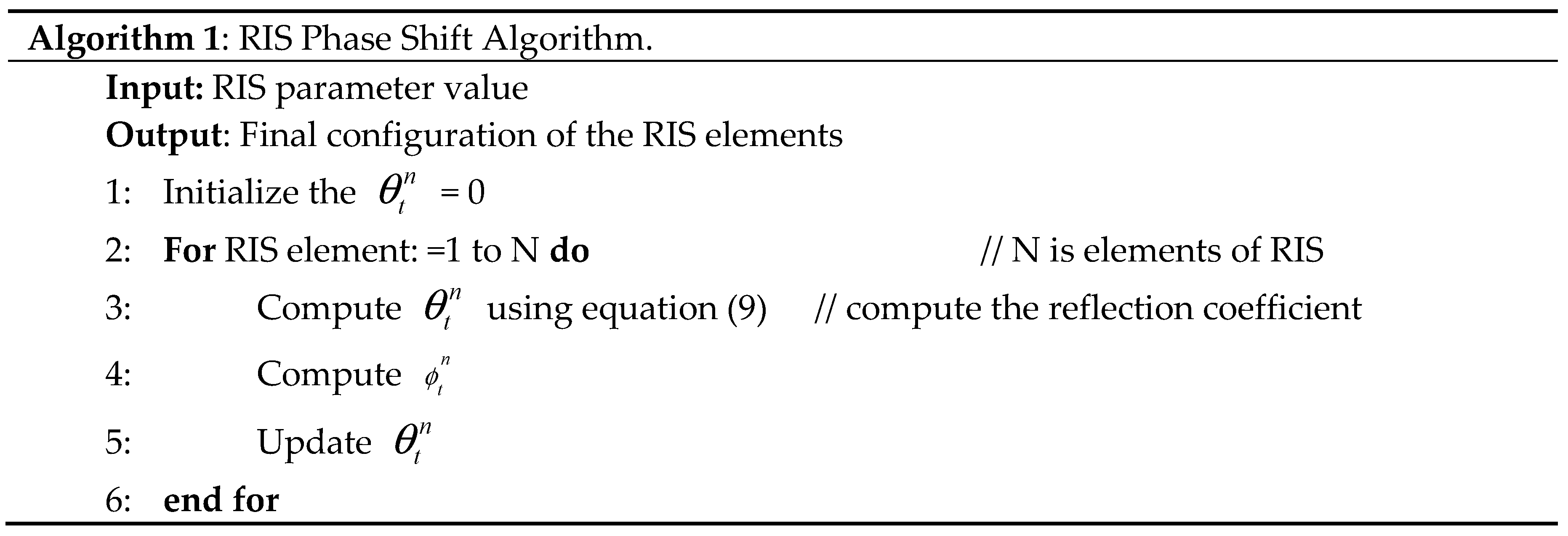
We used a MATLAB R2023a simulation tool to collect user channel data and RIS phase shift information. Through the simulation tool, we creating a simulation environment containing a UAV, RIS, and users. After created the simulation environment, we set up the simulation environment to setting up the parameters. After we defined the parameters, we generated the channel data according to Section 2.1 Channel Model mathematical expression. In simulating the RIS phase shift we defined our used RIS parameters such as the number of elements and reflection coefficients. We calculate the RIS phase shift depending on the channel modeling and the desired signal properties. In the next time slot, we update the phase shift at each RIS element based on the channel conditions and the specific algorithms we are using. Finally, generate user channel data and RIS phase shift by analyzing the received signal and extracting the relevant information for each user. This paper used a UAV with a fixed altitude and a horizontal trajectory so at each UAV trajectory we collect simulation user channel data. A RIS phase shift algorithm uses 9 elements of RIS to obtain data at a single location of a UAV and a single user. We obtained channel gain from each UAV location with each RIS element and from each user via the two links direct links (UAV-GU) and virtual links (UAV-RIS-GU).
We collected data from each position of UAV and in each position of UAV by changing 9 RIS elements. To express the mathematical expressions, we represent each position of the UAV with the index variable 'j', ranging from 1 to d and we represent each RIS element with the index variable 'k', ranging from 1 to 9. Based on these notations we expressed the given statements as a mathematical expression:
where, Ds (j, k) represents the data collected at UAV position “j” and RIS element “k”, the inner summation (Σ) runs over the RIS elements in each position (k = 1 to 9). Hence based on the above expression assumes that the data collected at each UAV position and RIS element can be combined in a meaningful way and based on these data we trained the model.
Data collected=∑∑Ds (j, k)
In this paper, we used the RIS phase shift algorithm. Algorithm 1 summarizes how the RIS phase shift is performed. Algorithm 2 summarizes the process of performing the RIS phase shift. It starts by initializing the RIS phase shift value to 0 and setting the maximum number of phase shift iterations depending on the number of RIS. The algorithm then enters a loop where it obtains the current CSI from the base station, calculates the optimal phase shift value based on the CSI, updates the RIS phase shift value, and increments the iteration counter. This loop continues until the iteration counter reaches the maximum number of iterations. Finally, the algorithm ends. By following this algorithm, the RIS phase shift can be effectively performed, allowing for improved wireless communication performance in RIS-assisted UAV communication systems.
The user data channel and RIS phase information can be denotes in the matrix for as
where X ∈ XMxF M donates the total records of the data, F is the number of features ri is a row vector in the ith row.
4.1.2. Data Preprocessing
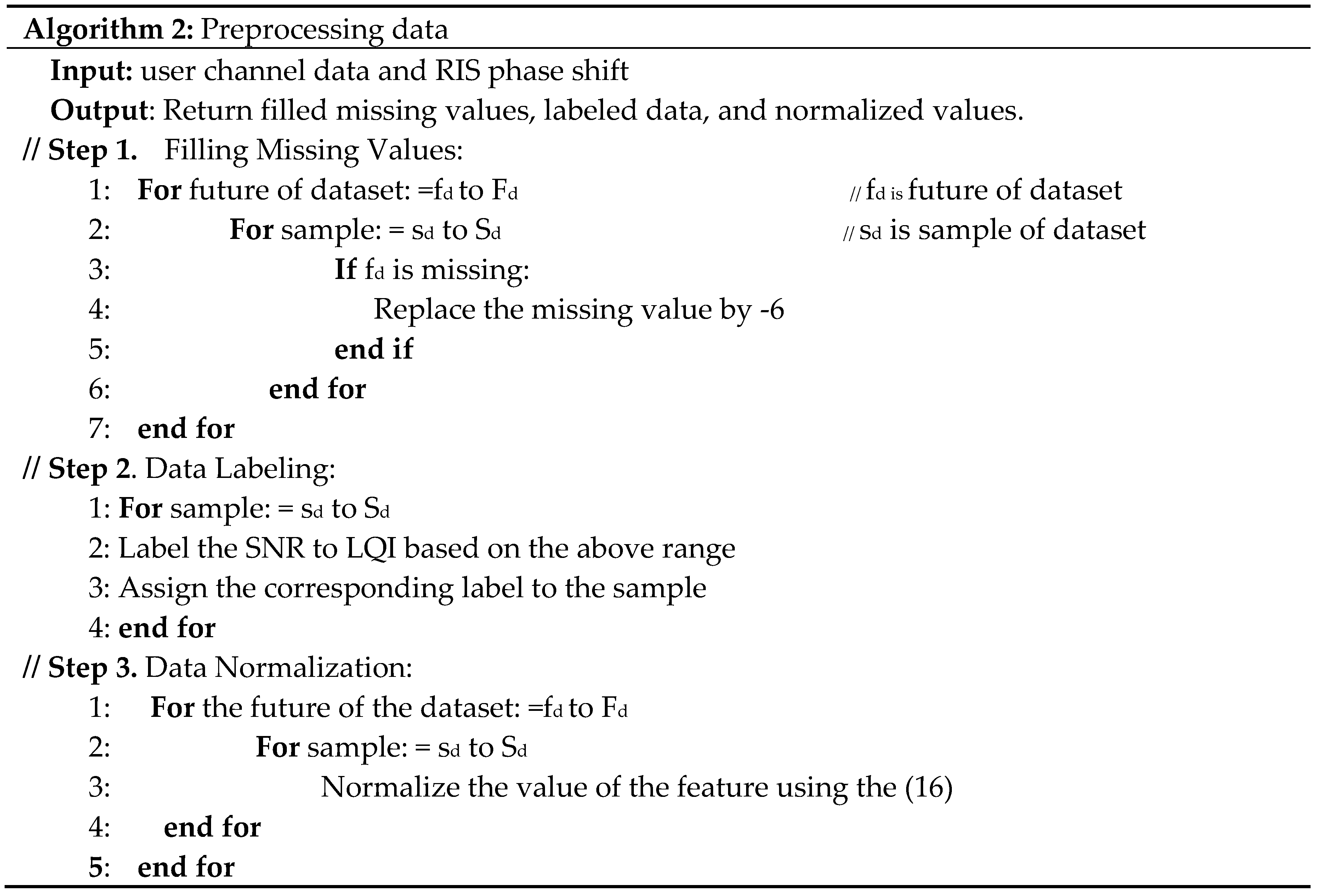
The data include channel data and RIS phase shifts. After acquiring the data from the target area, pre-processing is carried out to develop an accurate LQE model. Data pre-processing consists of filling missing values, data labeling (i.e., SNR to LQI) and data normalization to improve the training process and enhance neural networks' performance. We filling missing value preprocessing techniques in UAV communication when some users have not received signals. This issue we considered as a missing value, so in these techniques, we have filled these values. A user who doesn't receive a signal may be given a noise value, indicating that -6 should be filled in that missing SNR value after which we would apply data labeling to the data. After that, using filling missing values techniques, we label different link quality levels based on SNR value. For example, y = 1 for LQI = poor (SNR, less than 10), y = 2 for LQI = Fair (SNR, 10-20), y = 3 for LQI = good (SNR, 20-30), y = 4 for LQI = very good (SNR, 30-40), and y = 5 for LQI = excellent (SNR, greater than 40). Then we used the min-max normalization technique [17]. The link quality parameters in UAV communication are different. The data are normalized between 0 and 1 to eliminate range and reduce model error. The min-max normalization technique enables the data to be independent of the range and reduces the model error. It is also beneficial for the model to learn more from the data. Additionally, it makes the data easier to use for further analysis. To do this, we applied the min-max normalization formula, which maps the data between 0 and 1. This allows us to compare data from different ranges and make more accurate predictions. The min-max normalization technique also ensures that the data is not affected by outliers, making the model more robust. Furthermore, it helps to reduce the time needed for training the model. The normalization process is shown in (17) as follows:
where s is the original data and s' is the normalized data. After normalization, the data are ready to feed into the neural network. Normalization helps the neural network to learn faster and more accurately. It also helps prevent the network from getting stuck in local minima. Finally, it ensures that the weights of the network are not skewed by the presence of outliers in the data.
Algorithm 2 provides a comprehensive approach to preprocessing user channel data with RIS phase shift. By filling in missing values, data labeling, and applying min-max normalization, the resulting data will be ready for further analysis and modeling tasks.
4.1.3. Build Link Quality Estimation Model
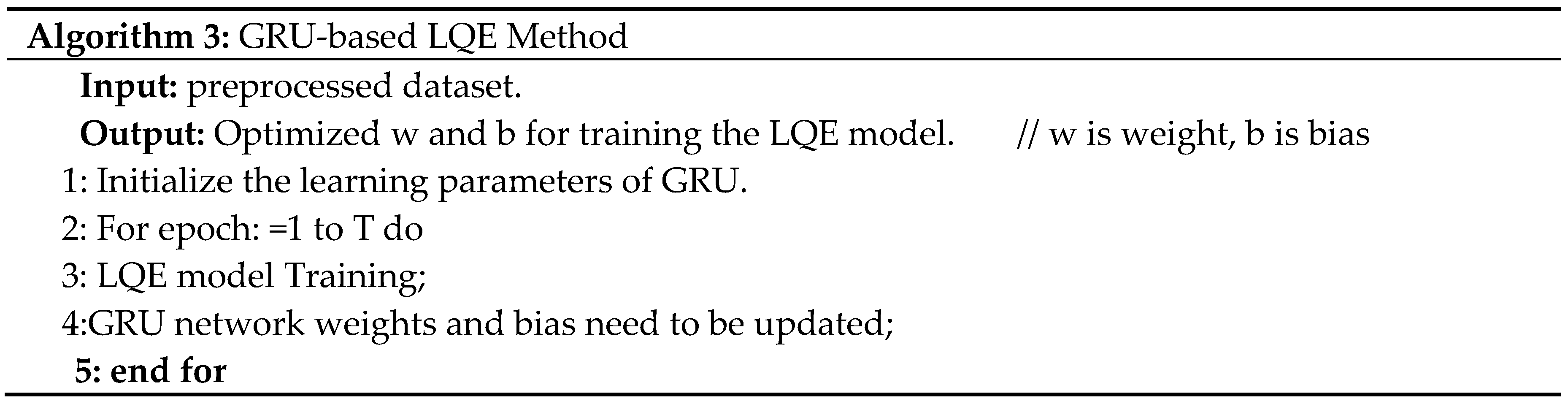
To address the LQE problem of RIS-assisted UAV communication systems, we employ a GRU algorithm. A simulation user channel data and the RIS phase shift information are used as input. Among various channel data parameters, we consider the SNR to label link quality indicator for GRU based LQE model. The GRU model is trained on the user channel data and RIS phase shift dataset. Once the features have been normalized as described in the preprocessing section using Algorithm 2, the GRU model is applied to them. Accordingly, the GRU-based LQE model training uses a normalized dataset as inputs and the corresponding LQI as outputs. During training, the trial-and-error method adjusts the network hyperparameters [28] listed in Table 3 until the optimal GRU model is achieved. As part of the RIS-assisted UAV communication system, a well-trained LQE model is uploaded to the UAV to continuously monitor the link quality. GRU LQE method algorithms 3 and 4 summarize the detailed training process.
LQE model offline training: We use the input data X = (r1, r2,...., rI) to denote the sequence of input data vectors and Y for the corresponding LQI. The proposed LQE model is trained using preprocessed user channel data and the corresponding LQI. Next, the model predicts the output's LQI.

LQE model online training: After being trained offline, the LQE model is used by the UAV to predict ground user link quality over time using Algorithm 4. The estimated ground user link quality is input to optimize UAV mobility for deployment of RIS-assisted UAV enabled wireless communications.
5. Result
5.1. Simulation Setup
In this scenario, a single UAV transmits a signal to GUs and an RIS is deployed on a building within a 200 m x 200 m urban area. RIS is located at the coordinates [40, 74, 50]. Ld0 = [27, 121, 50] is UAV initial location and flies 50 m a fixed altitude. The timeslot length is set to 1 second and the number of timeslots to 250. MATLAB R2023a is used to conduct the user channel data simulations. The simulation parameters are listed in Table 2.
5.2. Result and Discussion
We conducted experiments collecting RIS phase information and user channel data. 80% of the data was selected to train the LQE model while the remaining 20% was used for testing. To prepare the data for model, Algorithm 1 preprocessed it into a suitable structure.
The performance of each position of UAV in terms of LQI value can be analyzed to identify which UAV position is most suitable to serve service to the GUs. In this paper, we consider 100 positions of UAV so we need to analyze each position of LQI value to choose the best position and to also identify which better link. Figure 4 shows the performance of each position of UAV in terms of the average LQI value.
As shown in Figure 4, positions 12th, 19th, 29th, and 88th have a higher LQI value, which means those positions’ UAVs have better communication performance or have better links with ground users, so we can deploy directly in those positions. This information can help optimize UAV trajectory planning, resource allocation, and communication protocols to enhance overall network performance. However, in when consider mobility ground users we need to develop un optimized UAV trajectory control and phase shift optimization in order to provide better communication service in target area. Accordingly, our proposed LQE model helps to accurately deploy RIS-assisted UAV-enabled communication systems to provide continuous wireless service.
In a RIS-assisted UAV communication system, deploying a RIS near the UAV's communication path can enhance the link quality between the UAV and the ground station or other UAVs. In RIS each element of RIS can reflect incident signals with different phase shifts so in our scenario we used a 3 by 3 matrix (3x3) or 9 elements of RIS each element is active during all time slots but each element of RIS reflecting performance depends on the location of UAV and location of the ground user.
In Figure 5, shows the average LQI performance of each RIS element. According to the results of the experiments from all RIS elements, the 5th element has a higher LQI on average than other elements of RIS. Thus, in RIS assisted communication system by measuring all elements of RIS we should select the better element of RIS we will get a better signal of the complexity and also select a better link between UAV and the ground users. We can improve the overall performance of communication links by selecting the best element of RIS. Furthermore, it allows us to establish a better connection between UAVs and ground users.
To build the GRU proposed system use the preprocessed dataset and we need to compare the GRU and the LSTM algorithms using common parameters, evaluating the GRU algorithm's performance. The evaluation was conducted using similar layers, optimizer, batch sizes, and epochs to avoid bias. Table 3 lists the optimal learning hyperparameters for GRU-based link quality estimation. Figure 6 shows a comparison of the link quality estimation performance of GRU and LSTM. As training and validation epochs increase in size, the fitting lines diverge in the LSTM algorithm. The GRU model, on the other hand, demonstrates better performance on larger datasets with fewer overfitting issues. Thus, GRU is the better option for avoiding bias in system performance evaluations. Therefore, the GRU model is preferred for use in larger datasets, as it is better equipped to handle the complexity and volume of data while maintaining accuracy. This makes it the optimal choice for many deep-learning applications.
In Figure 6, both LSTM and GRU exhibit fluctuations in the original data as the number of epochs increases, but both algorithms show improved performance. However, the GRU algorithm experiences a greater performance loss of over 0.058. Additionally, the data suggests that GRU offers better integrity than other algorithms for accurate link quality prediction.
We used accuracy and cross-entropy to evaluate the model as showed in Table 4. The LSTM and GRU models predict cross-entropy values of 0.12 and 0.062, respectively, in the original data. The GRU has a better cross-entropy value than LSTM, indicating that it is better for link quality estimation algorithm in RIS-assisted UAV communication systems.
We develop the GRU LQE model based on Table 3 hyperparameters to estimate LQI. Making predictions on newly available data will allow you to estimate link quality for unseen samples using the trained GRU model.
According to Figure 7, the GRU model correctly predicted the LQI. The link quality value is accurately estimated when a system achieves optimal performance.
The performance comparison between with and without RIS link quality estimations. Based on our developed model we compared the link quality between UAV and ground users by considering the RIS and without an RIS for UAV communications.
In Figure 8 shows the performance comparison between with and without RIS link quality estimations. According to the experiment, with RIS the average link quality is 3-4 LQI values, which means the communication performance is good up to excellent quality communication. In contrast, without RIS the average link quality is 1-3 LQI, which means the communication performance is poor to good quality communication. Thus, with RIS UAV communication system is more powerful and capable of better communication than without RIS UAV communication system. Therefore, RIS-assisted UAV communication systems offer significant improvements in link quality compared to traditional UAV communication without RIS. RIS technology allows dynamic adaptation to changing environments, interference mitigation, and focused signal transmission. This leads to enhanced reliability, coverage, and better link quality in UAV communications. However, the specific benefits of RIS will depend on the optimization algorithms, the number of RIS elements, deployment scenarios, and other system parameters.
6. Conclusions
In this paper, we proposed a link quality estimation model for RIS-assisted UAV-enabled communication system to improve the conventional UAV assisted wireless communication system performance. To estimate the link quality of a RIS-assisted UAV communication system, we proposed a GRU model by training it using user channel data and RIS configuration information. We evaluated our proposed system using simulation user channel data. Simulation results showed that utilizing GRU can effectively enhance the performance of link quality estimation for RIS-assisted UAV-enabled wireless communication. In future work, our plan is to focus on the deployment of RIS-assisted UAV wireless communication systems by considering 3D UAV trajectory and RIS phase shift to significantly improve channel fading effects, as well as further enhancing user throughput and communication coverage.
Author Contributions
Belayneh Abebe Tesfaw contributed to the experiment, analyzed the data, wrote the program, and prepared the manuscript. The problem was suggested by Hsin-piao Lin, suggestions were given, and instructions regarding the work were given. During the discussion, Rong-Terng Juang provided suggestions and comments. Getaneh Berie contributed to the experiment, and write a program with Belayneh. Kabore Wendenda Nathanael contributed to analyzing the data and writing the program with Belayneh. Shiann-Shiun Jang collected relative references and provided comments. Finally, all authors have read and approved the final manuscript version.
Funding
This research was funded by the National Science and Technology Council (Grant No: 112-2221-E-027-123).
Institutional Review Board Statement
Not applicable.
Informed Consent Statement
Not applicable.
Data Availability Statement
Not applicable.
Acknowledgments
This research is partially supported by National Science and Technology Council.
Conflicts of Interest
The authors declare no conflict of interest.
References
- Balador, A.; Kouba, A.; Cassioli, D.; Foukalas, F.; Severino, R.; Stepanova, D.; Agosta, G.; Xie, J.; Pomante, L.; Mongelli, M.; et al. Wireless Communication Technologies for Safe Cooperative Cyber Physical Systems. Sensors (Switzerland) 2018, 18. [Google Scholar] [CrossRef] [PubMed]
- Zeng, Y.; Zhang, R.; Lim, T.J. Wireless Communications with Unmanned Aerial Vehicles: Opportunities and Challenges. 2016. [Google Scholar] [CrossRef]
- Telli, K.; Kraa, O.; Himeur, Y.; Ouamane, A.; Boumehraz, M.; Atalla, S.; Mansoor, W. A Comprehensive Review of Recent Research Trends on Unmanned Aerial Vehicles (UAVs). Systems 2023, 11, 400. [Google Scholar] [CrossRef]
- Zeng, Y.; Zhang, R.; Lim, T.J. Wireless Communications with Unmanned Aerial Vehicles: Opportunities and Challenges. IEEE Communications Magazine 2016, 54, 36–42. [Google Scholar] [CrossRef]
- Fan, X.; Liu, M.; Chen, Y.; Sun, S.; Li, Z.; Guo, X. RIS-Assisted UAV for Fresh Data Collection in 3D Urban Environments: A Deep Reinforcement Learning Approach. IEEE Trans Veh Technol 2023, 72, 632–647. [Google Scholar] [CrossRef]
- ElMossallamy, M.A.; Zhang, H.; Song, L.; Seddik, K.G.; Han, Z.; Li, G.Y. Reconfigurable Intelligent Surfaces for Wireless Communications: Principles, Challenges, and Opportunities. 2020.
- Park, K.W.; Kim, H.M.; Shin, O.S. A Survey on Intelligent-Reflecting-Surface-Assisted UAV Communications. Energies (Basel) 2022, 15. [Google Scholar] [CrossRef]
- Pogaku, A.C.; Do, D.T.; Lee, B.M.; Nguyen, N.D. UAV-Assisted RIS for Future Wireless Communications: A Survey on Optimization and Performance Analysis. IEEE Access 2022, 10, 16320–16336. [Google Scholar] [CrossRef]
- Abdalla, A.S.; Rahman, T.F.; Marojevic, V. UAVs with Reconfigurable Intelligent Surfaces: Applications, Challenges, and Opportunities. 2020.
- Institute of Electrical and Electronics Engineers 2020 IEEE International Conference on Communications Workshops (ICC) : Proceedings : Dublin, Ireland, 7-11 June 2020. ISBN 9781728174402.
- Ren, H.; Zhang, Z.; Peng, Z.; Li, L.; Pan, C. Energy Minimization in RIS-Assisted UAV-Enabled Wireless Power Transfer Systems. IEEE Internet Things J 2023, 10, 5794–5809. [Google Scholar] [CrossRef]
- Mohsan, S.A.H.; Othman, N.Q.H.; Li, Y.; Alsharif, M.H.; Khan, M.A. Unmanned Aerial Vehicles (UAVs): Practical Aspects, Applications, Open Challenges, Security Issues, and Future Trends. Intell Serv Robot 2023, 16, 109–137. [Google Scholar] [CrossRef] [PubMed]
- Shi, B.; Wang, Y.; Li, D.; Cai, W.; Lin, J.; Zhang, S.; Shi, W.; Yan, S.; Shu, F. STAR-RIS-UAV-Aided Coordinated Multipoint Cellular System for Multi-User Networks. Drones 2023, 7, 403. [Google Scholar] [CrossRef]
- Asif, M.; Ihsan, A.; Khan, W.U.; Ranjha, A.; Zhang, S.; Wu, S.X. Energy-Efficient Beamforming and Resource Optimization for AmBSC-Assisted Cooperative NOMA IoT Networks. 2022.
- Luo, X.; Liu, L.; Shu, J.; Al-Kali, M. Link Quality Estimation Method for Wireless Sensor Networks Based on Stacked Autoencoder. IEEE Access 2019, 7, 21572–21583. [Google Scholar] [CrossRef]
- Cerar, G.; Yetgin, H.; Mohorčič, M.; Fortuna, C. On Designing a Machine Learning Based Wireless Link Quality Classifier. 2020. [Google Scholar] [CrossRef]
- Dargie, W.; Wen, J. A Link Quality Estimation Model for a Joint Deployment of Unmanned Aerial Vehicles and Wireless Sensor Networks. In Proceedings of the Proceedings - International Conference on Computer Communications and Networks, ICCCN; Institute of Electrical and Electronics Engineers Inc., 1 July 2021. [Google Scholar]
- Tarekegn, G.B.; Juang, R.T.; Lin, H.P.; Munaye, Y.Y.; Wang, L.C.; Jeng, S.S. Channel Quality Estimation in 3D Drone Base Station for Future Wireless Network. In Proceedings of the 2021 30th Wireless and Optical Communications Conference, WOCC 2021; Institute of Electrical and Electronics Engineers Inc, 2021; pp. 236–239. [Google Scholar]
- Tarekegn, G.B.; Juang, R.T.; Lin, H.P.; Munaye, Y.Y.; Wang, L.C.; Bitew, M.A. Deep-Reinforcement-Learning-Based Drone Base Station Deployment for Wireless Communication Services. IEEE Internet Things J 2022, 9, 21899–21915. [Google Scholar] [CrossRef]
- Kang, H.; Joung, J.; Kang, J. A Study on Probabilistic Line-of-Sight Air-to-Ground Channel Models.
- Van Brandt, S.; Van Thielen, R.; Verhaevert, J.; Van Hecke, T.; Rogier, H. Characterization of Path Loss and Large-Scale Fading for Rapid Intervention Team Communication in Underground Parking Garages. Sensors (Switzerland) 2019, 19. [Google Scholar] [CrossRef] [PubMed]
- Ma, X.; Chen, Z.; Chen, W.; Li, Z.; Chi, Y.; Han, C.; Li, S. Joint Channel Estimation and Data Rate Maximization for Intelligent Reflecting Surface Assisted Terahertz MIMO Communication Systems. IEEE Access 2020, 8, 99565–99581. [Google Scholar] [CrossRef]
- Kim, J.; Yu, H.; Kang, X.; Joung, J. Discrete Phase Shifts of Intelligent Reflecting Surface Systems Considering Network Overhead. Entropy 2022, 24. [Google Scholar] [CrossRef] [PubMed]
- Luo, X.; Liu, L.; Shu, J.; Al-Kali, M. Link Quality Estimation Method for Wireless Sensor Networks Based on Stacked Autoencoder. IEEE Access 2019, 7, 21572–21583. [Google Scholar] [CrossRef]
- Yue, B.; Fu, J.; Liang, J. Residual Recurrent Neural Networks for Learning Sequential Representations. Information (Switzerland) 2018, 9. [Google Scholar] [CrossRef]
- Tarekegn, G.B.; Tai, L.C.; Lin, H.P.; Tesfaw, B.A.; Juang, R.T.; Hsu, H.C.; Huang, K.L.; Singh, K. Applying T-Distributed Stochastic Neighbor Embedding for Improving Fingerprinting-Based Localization System. IEEE Sens Lett 2023. [CrossRef]
- Tarekegn, G.B.; Juang, R.T.; Lin, H.P.; Tai, L.C.; Munaye, Y.Y.; Bitew, M.A. SRCLoc: Synthetic Radio Map Construction Method for Fingerprinting Outdoor Localization in Hybrid Networks. IEEE Sens J 2022, 22, 15574–15583. [Google Scholar] [CrossRef]
- Blume, S.; Benedens, T.; Schramm, D. Hyperparameter Optimization Techniques for Designing Software Sensors Based on Artificial Neural Networks. Sensors 2021, 21. [Google Scholar] [CrossRef] [PubMed]
Figure 1.
The RIS-assisted UAV-enabled wireless communications system.
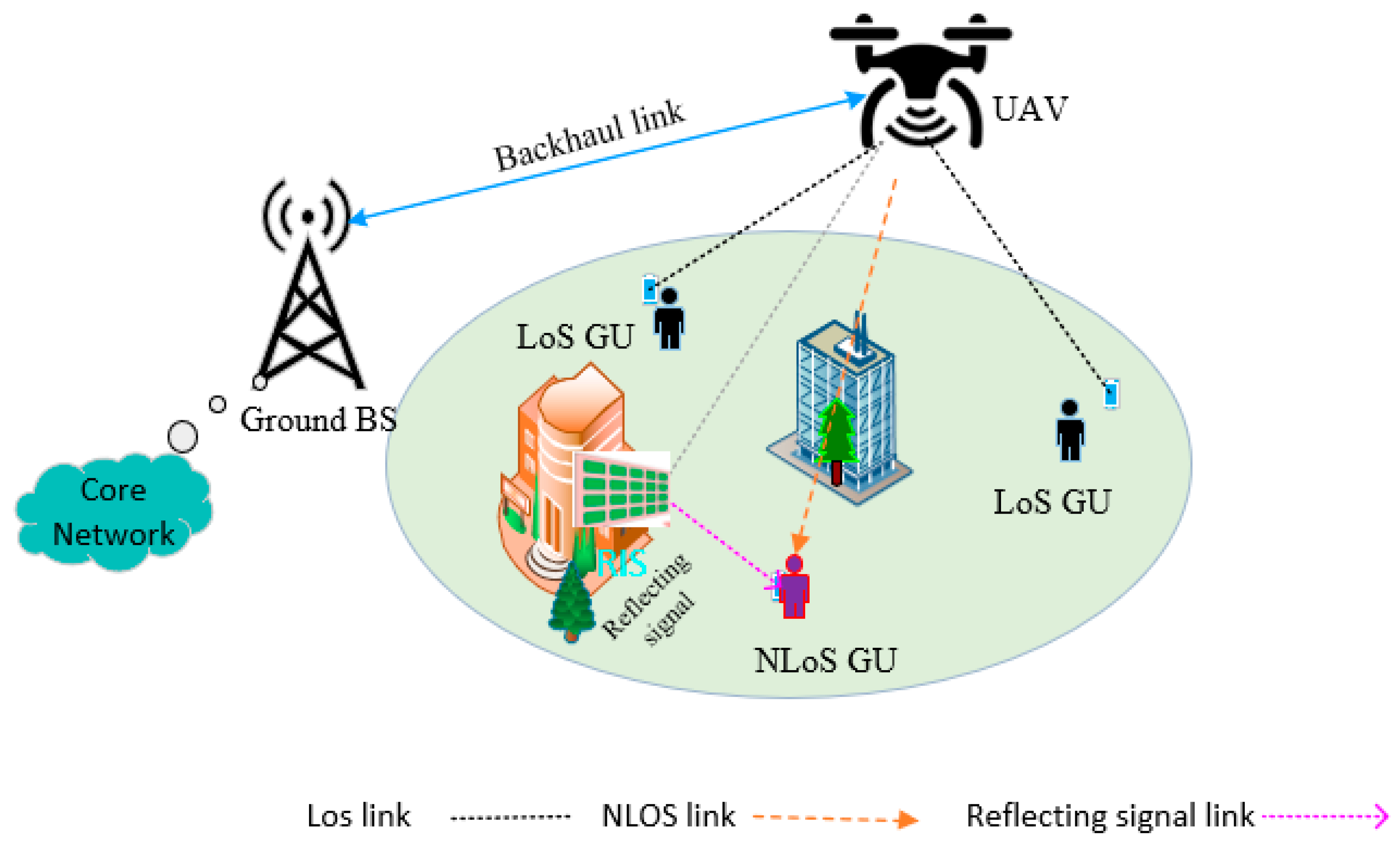
Figure 2.
GRU memory blocks.
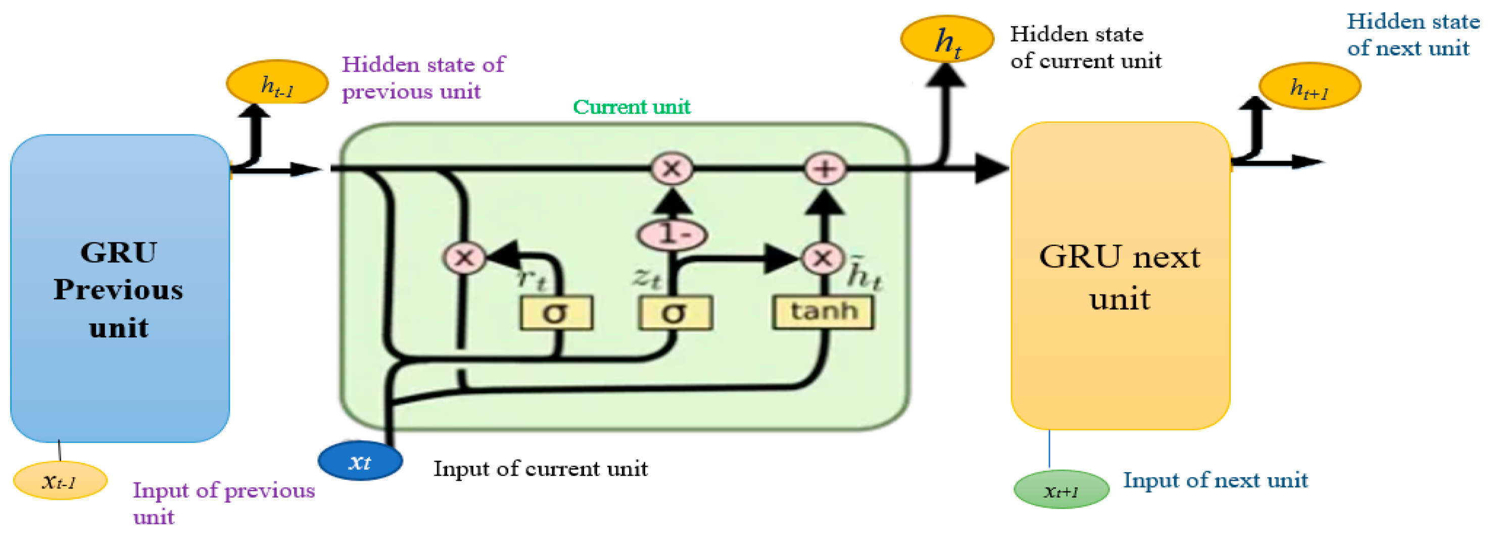
Figure 3.
The Architecture of the proposed link quality estimation system.
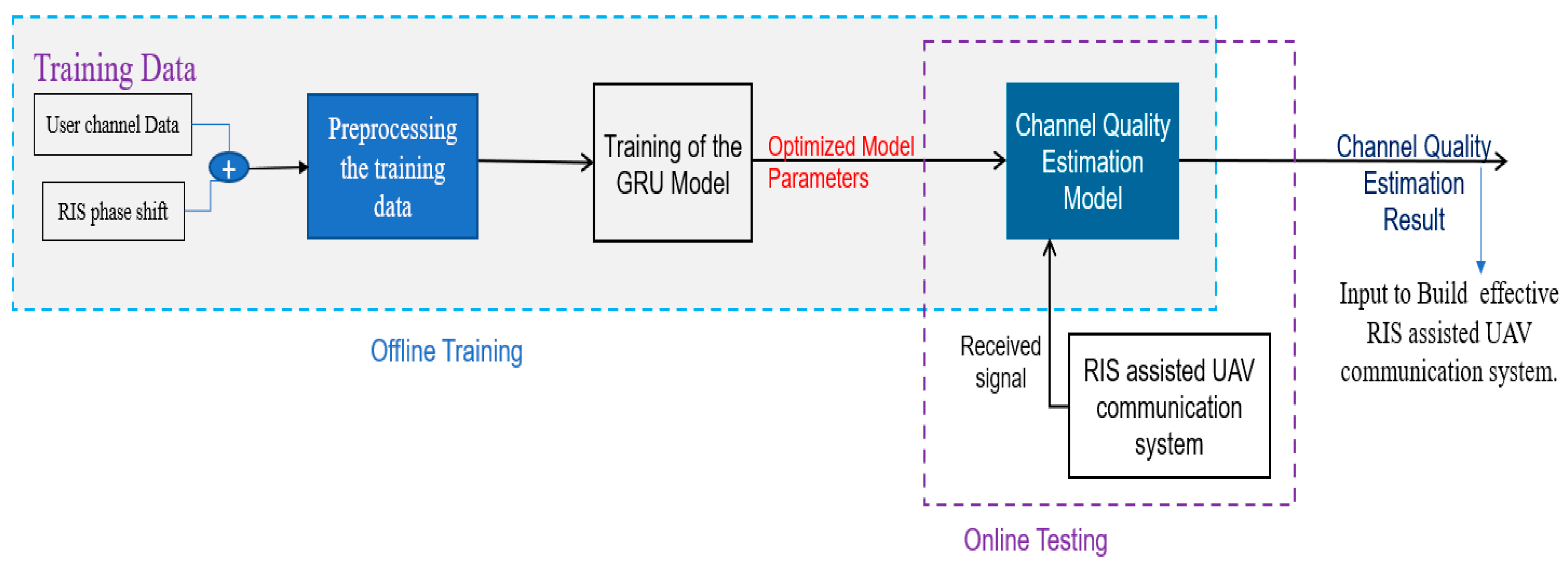
Figure 4.
Average LQI value performance with respect to each position of UAV.
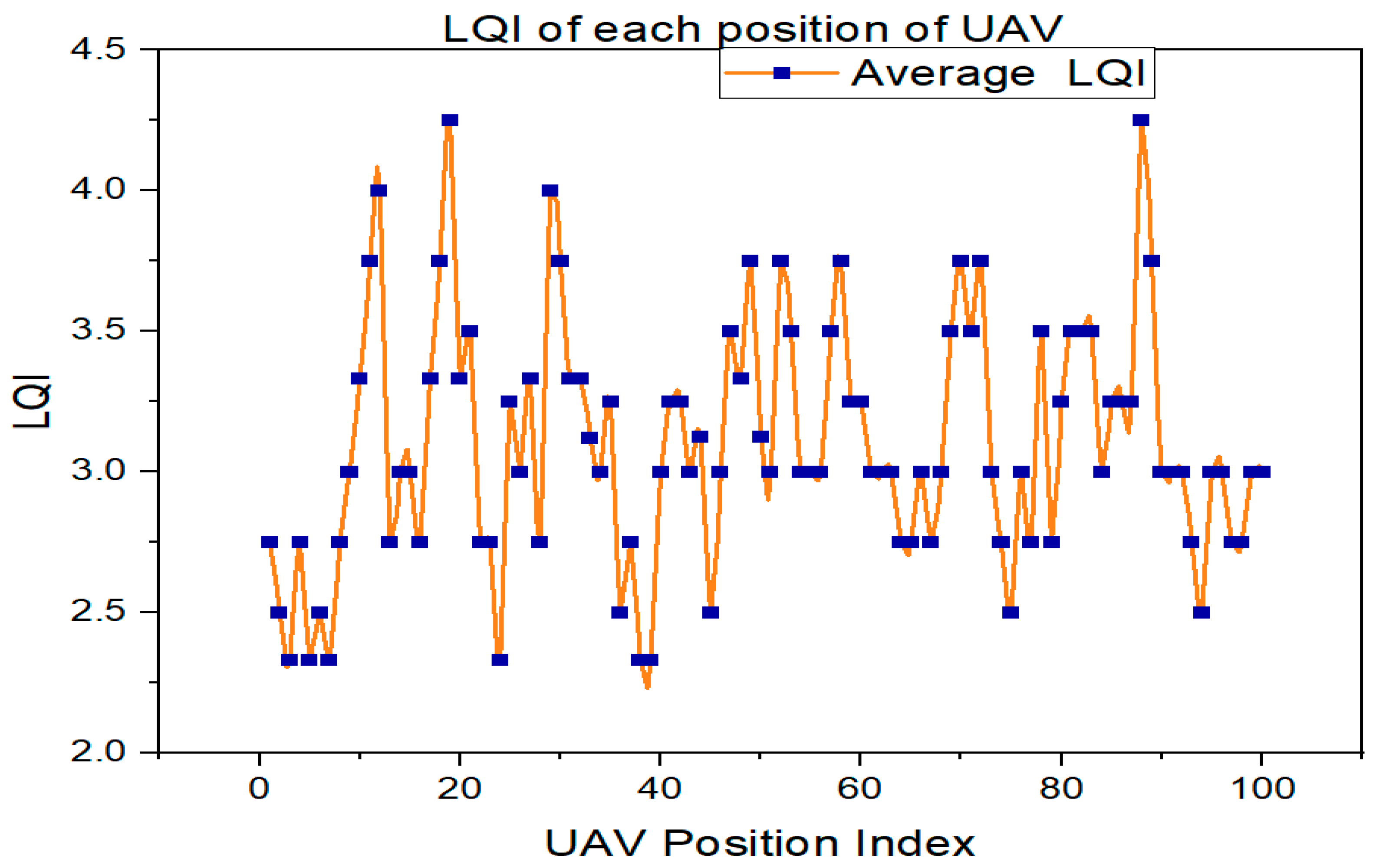
Figure 5.
The LQI performance of ground users in each element of RIS.

Figure 6.
Performance losses of the LSTM and GRU LQE model.
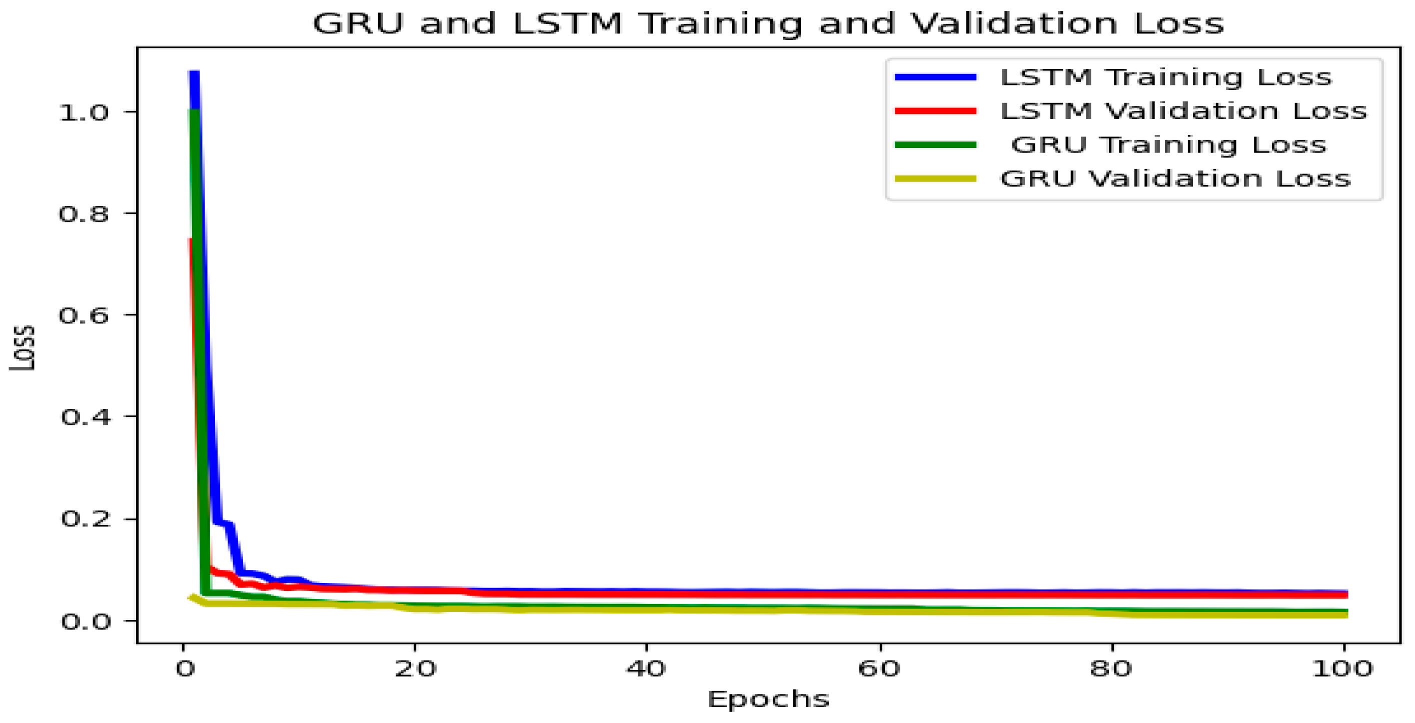
Figure 7.
Prediction performance of GRU LQE model.
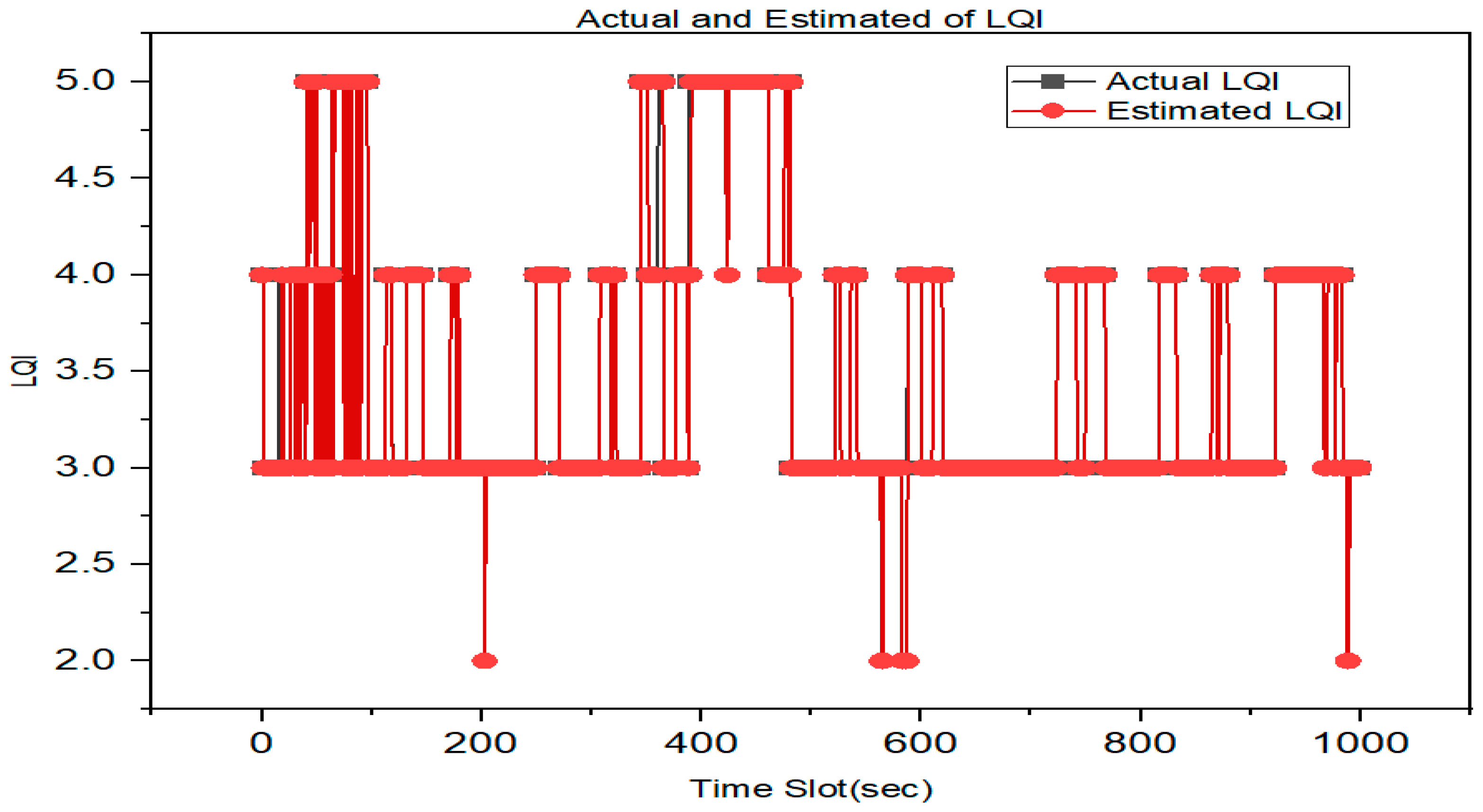
Figure 8.
The GRU LQE estimation performance of RIS-assisted and without RIS-assisted UAV communication.
Figure 8.
The GRU LQE estimation performance of RIS-assisted and without RIS-assisted UAV communication.
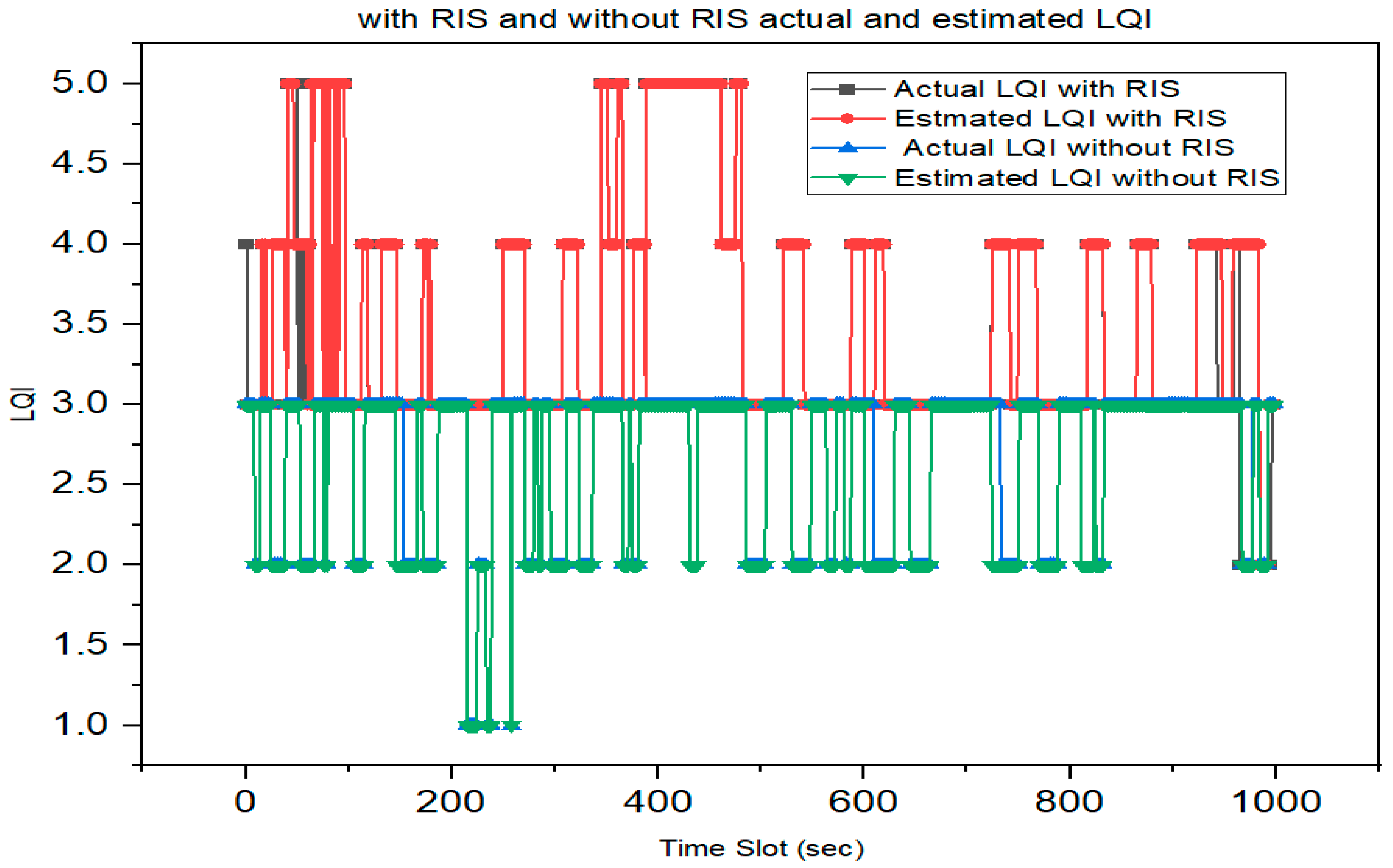

Table 2.
Simulation Parameter.
| Parameter | Value |
|---|---|
| Transmit power p | 0.1 W |
| Noise Power No | -80 dB |
| Path loss at 1m α | -20 dB |
| Path loss for LoS ηLoS | 0.2 dB |
| Path loss for NLoS ηNLoS | 21 dB |
| Carrier frequency fc | 2 GHz |
| Rician factor K1 | 3dB |
| Speed of light c | 3 × 10⁸ m/s |
| Path loss RIS-GU link β | 2.8 |
| Number of RIS elements N | 9 |
| quantization bits b | 4 bits |
Table 3.
The Deep learning network parameters.
| Parameter | Value |
|---|---|
| Number of hidden layers | 3(128,64,32 neurons) |
| Dropout | 0.2 |
| Batch size | 32 |
| Learning rate | 0.001 |
| Loss function | Cross-entropy |
| Optimization algorithm | Adam |
| Number of epochs | 100 |
Table 4.
LQE performance evaluation.
| Performance Metrics | LSTM | GRU |
|---|---|---|
| Accuracy | 0.95 | 0.96 |
| Cross-entropy | 0.12 | 0.062 |
Disclaimer/Publisher’s Note: The statements, opinions and data contained in all publications are solely those of the individual author(s) and contributor(s) and not of MDPI and/or the editor(s). MDPI and/or the editor(s) disclaim responsibility for any injury to people or property resulting from any ideas, methods, instructions or products referred to in the content. |
© 2023 by the authors. Licensee MDPI, Basel, Switzerland. This article is an open access article distributed under the terms and conditions of the Creative Commons Attribution (CC BY) license (https://creativecommons.org/licenses/by/4.0/).
Copyright: This open access article is published under a Creative Commons CC BY 4.0 license, which permit the free download, distribution, and reuse, provided that the author and preprint are cited in any reuse.


