1. Introduction
Magnetic fluid (MF), also known as ferromagnetic fluid, is a new type of functional material. It has not only the fluidity of liquid, but also the magnetism of solid magnetic material. MF is a stable colloidal liquid which is composed of magnetic nanoparticles, liquid carriers, and surfactant[
1]. The magnetic nanoparticles can be prepared by chemical coprecipitation[
2]. The magnetic nanoparticles surrounded by surfactants are evenly dispersed in the liquid carriers. The refractive index of MF depicts a linear relationship with the concentration of magnetic nanoparticles. As the external magnetic field intensity is higher than a critical value, the relationship between the refractive index of MF and magnetic field complies the Langevin equation[
3]. Owing to the magneto-optical characteristics of MF, many optical devices such as wavelength filters, optical switches and magnetic field sensors have been proposed[
4,
5,
6,
7]. Photonic crystal fiber (PCF), also known as microstructured optical fiber or holey fiber, was firstly fabricated by Knight, J. C. et al. in 1996[
8]. Moutusi De et al. designed a magnetic field sensor with a sensitivity of 799.07 pm/Oe using square lattice PCF[
9]. Li et al. designed a sensor for magnetic fields built on an MF-filled DC-PCF. The two MF-filled air holes serve as two separate waveguides. The sensitivity was 4.8 pm/Oe based on the modes coupling effect[
10]. Liu et al. investigated a PCF Sagnac interferometer filled with MF and found that it had an average sensitivity of 384 pm/Oe between 410 and 600 Oe[
11]. Xu et al. designed a novel PCF magnetic field sensor with two elliptic center holes filled with magnetic fluid and some elliptic cladding air holes. The sensitivity of the magnetic sensor was calculated. The numerical simulation results showed that the maximum sensitivity of the magnetic sensor could reach 1200 pm/Oe[
12]. However, according to the previously reported DC-PCF magnetic field sensors, the structure of PCF was usually complex. Even in some PCFs, light is transmitted in the high loss magnetic fluid. It is essential to investigate a DC-PCF magnetic field sensor with high sensitivity and vitally light transmission in silica core.
In this paper, a magnetic field sensor based on a MF-filled DC-PCF was investigated using the finite element method. Only one central air hole in the DC-PCF was designed to be infiltrated with MF. The mode coupling effect between the supermodes could be adjusted by the external magnetic field. Numerical results showed that the measuring sensitivity reached 515.75 pm/Oe. The wavelength shift showed a linear relationship with the magnetic field intensity in the range of 80-260 Oe, which made it a significant candidate in the measurement of magnetic field.
2. MF-Filled DC-PCF and Operation Principle
As seen in
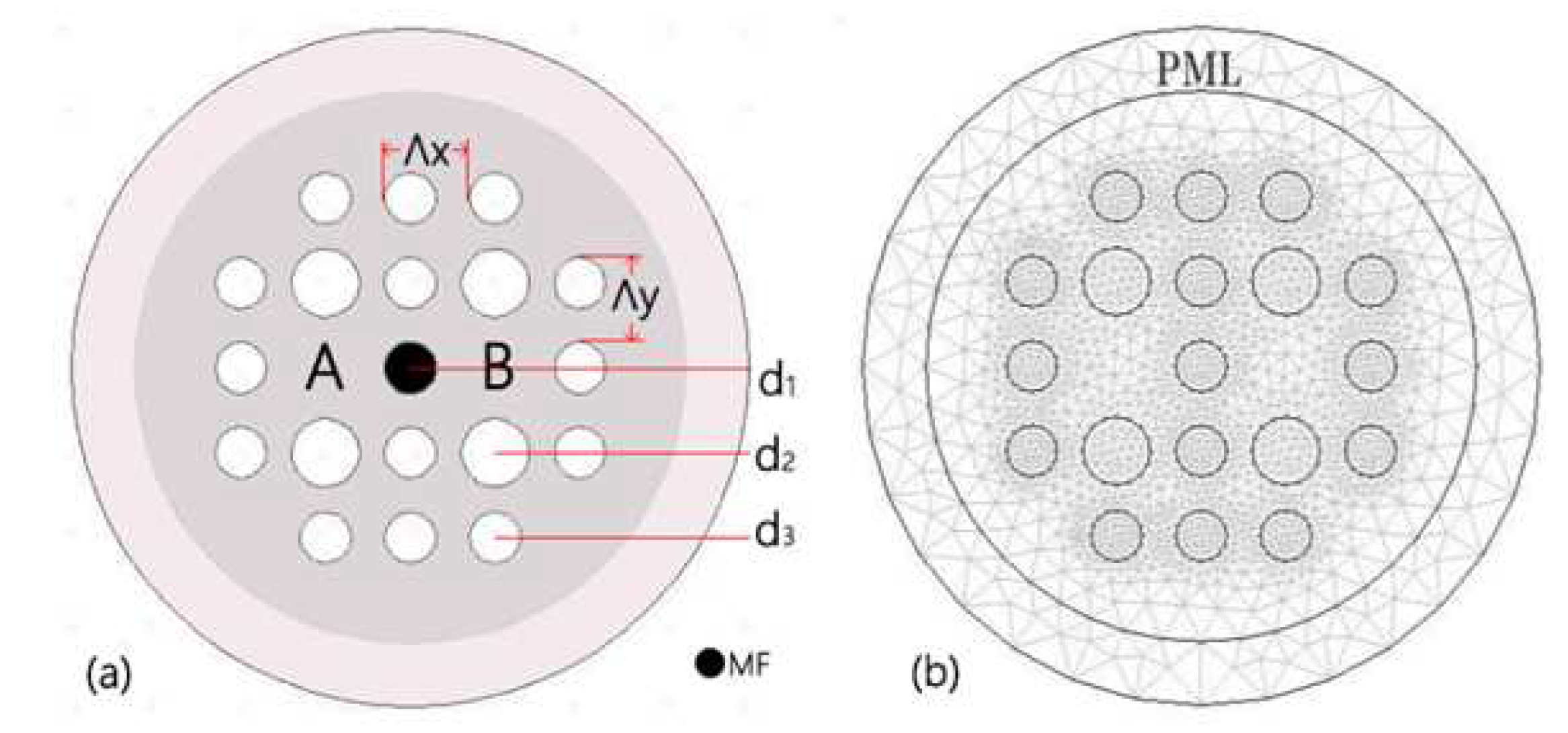
Figure 1(a), the cross-section of the MF-filled DC-PCF. The air holes are arranged in a rectangular lattice. Compared with hexagonal distribution, rectangular arrangement of holes can generate greater mode birefringence[
13]. Depicting larger mode birefringence leads to shorter coupling lengths. Thus, the size of the DC-PCF magnetic field sensor can be made much smaller. The spacing of surrounding voids are indicated by
in the horizontal direction and
in the vertical direction, respectively. Both the values of
and
are set at 2
m. The corresponding values of d
, d
, and d
represent the diameters of the tiny white, huge white, and small black air holes, respectively. These diameters are initially set at d
= 1.2
m, d
= 1.6
m, and d
= 1.2
m, respectively. It is well known that the efficient refractive indices of core modes are mainly influenced by its most adjacent air holes[
14]. To achieve magnetic field detection, the center air hole is fashioned as an MF infiltration hole. The filling technology demonstrated by[
15,
16], can be used to achieve the selective infilling of MF.
Figure 1(b) depicts the meshed cross-section of the DC-PCF. Perfectly Matched Layer (PML) is used to absorb the energy of the scattering light. The scattering boundary condition (SBC) acts as the PML’s outer boundary to further enhance the absorption of scattering light. The COMSOL Multiphysics software meshes the computational region using free triangles. The DC-PCF is meshed into about 16814 elements. In the designed DC-PCF, the refractive index of air is set as n
= 1. Fused silica glass serves as the back ground material of DC-PCF, and the Sellmeier equation can be used to determine its material dispersion[
17].
where
is the wavelength in free space and its unit is
m. The parameters in Equation (
1) are m
= 0.6961663, m
= 0.4079426, m
= 0.8974794, k
= 0.0684043
m, k
= 0.1162414
m, and k
= 9.896161
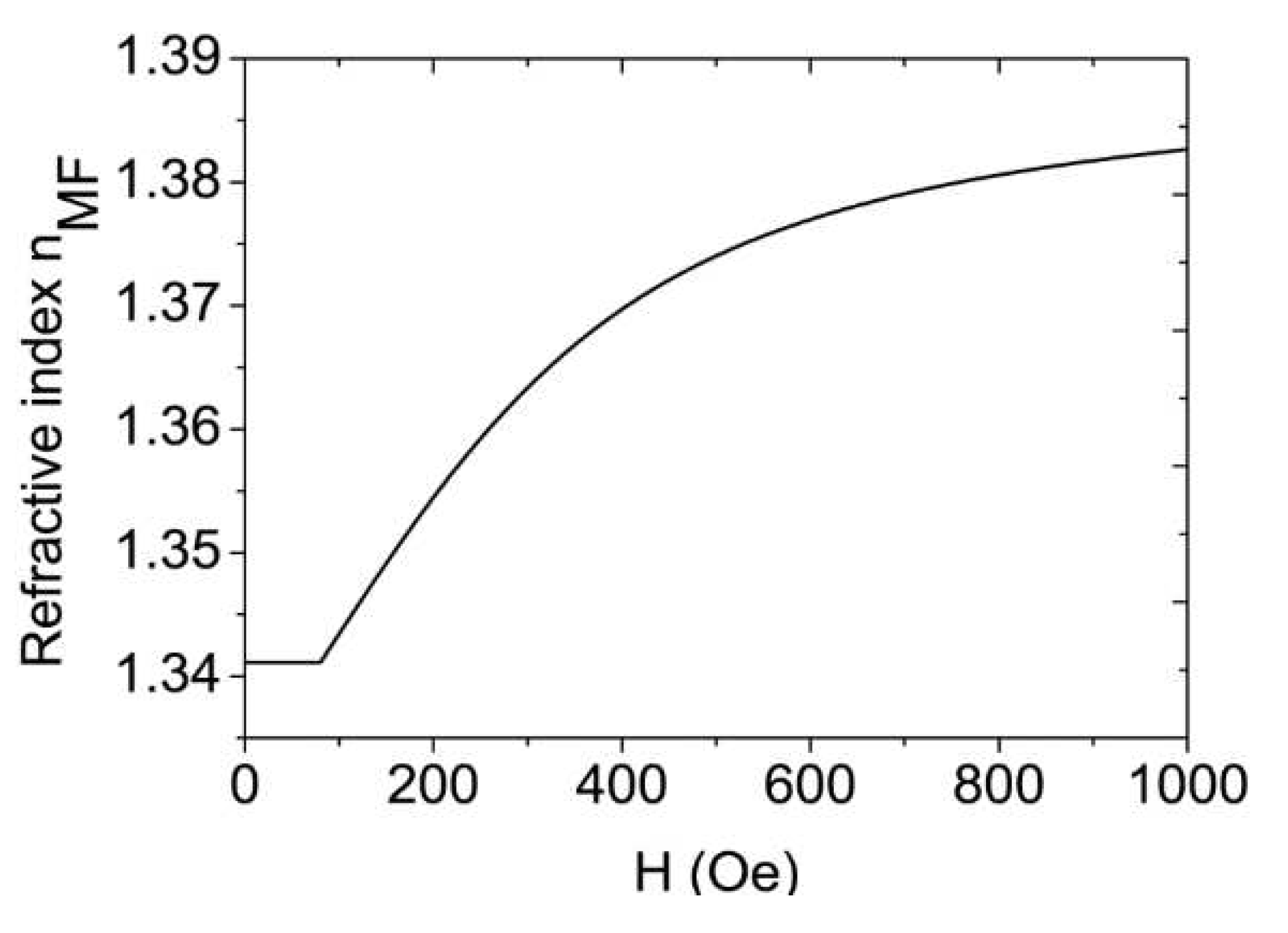
m. The Langevin function is followed by the refractive index of MF[
18].
where n(H, T) is the refractive index of the MF fluctuation with temperature and magnetic field strength, n
is the refractive index value as MF reaches the saturation magnetization, and the magnetic field’s threshold value is H
. The refractive index of MF is n
because the magnetic field H is smaller than H
. The temperature in Kelvin is T.
denotes the coefficient of the fitting.
In this paper, MF is carried by water as its liquid carrier, and its concentration is 25%. The parameters are H
= 80 Oe, n
= 1.3411, n
= 1.3901,
= 0.143, and T = 293 K[
18]. In
Figure 2, the refractive index of the MF fluctuation is shown along with the magnetic field strength H.
The block diagram of the suggested sensor based on an MF-filled DC-PCF is shown in
Figure 3. The MF-filled DC-PCF is spliced with two single mode fibers (SMFs). A broadband source (BBS) provides continuous light. The incident light is launched into the left SMF. Then, it passes through the MF-filled DC-PCF and enters the right SMF. It eventually arrives at the optical spectrum analyzer (OSA). The DC-PCF filled with MF is given a magnetic field by the solenoid, which is then used to modify the MF’s refractive index.
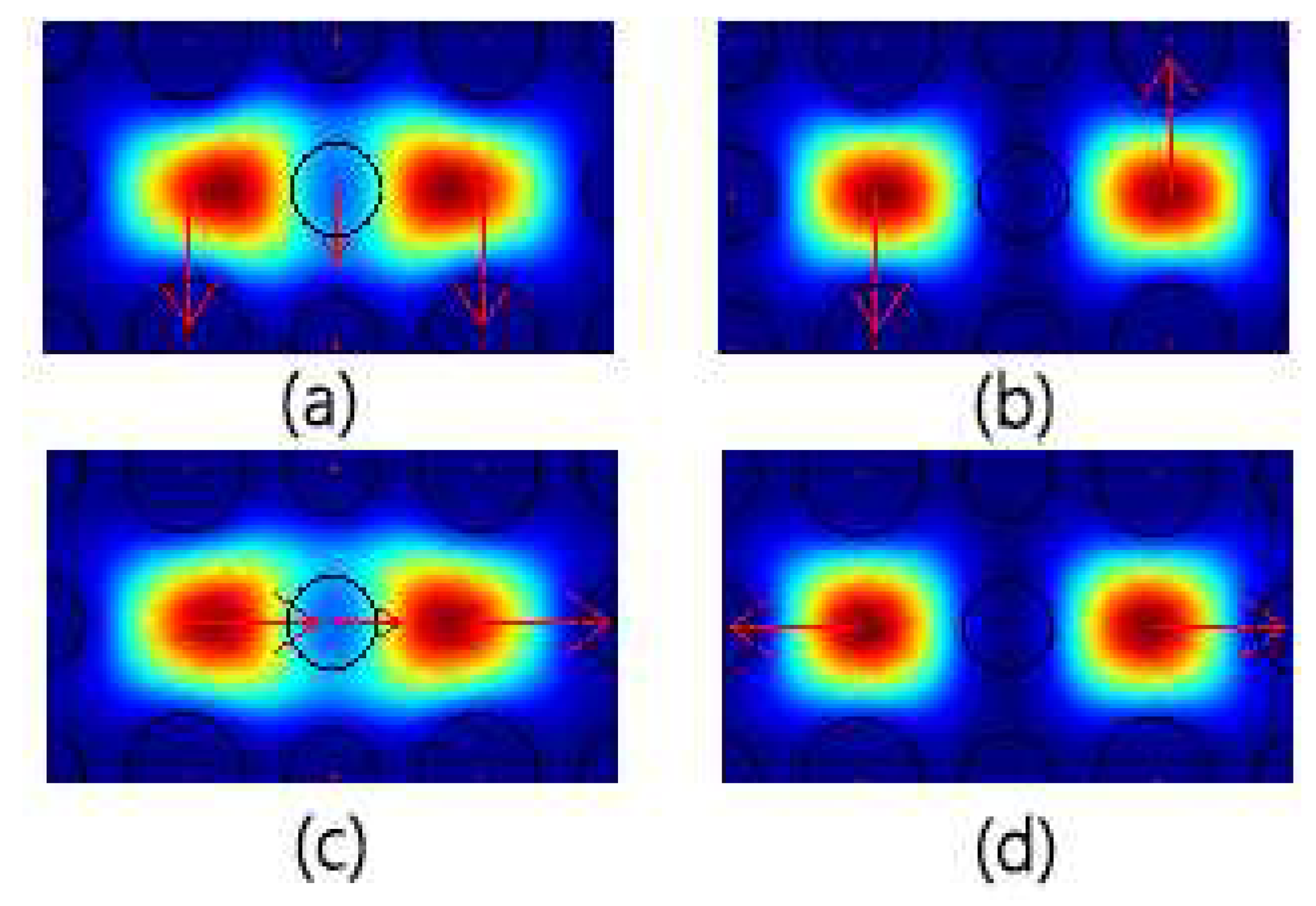
The two silica cores besides the central MF-filled hole in DC-PCF form two independent waveguides. According to the supermodes theory, there are four supermodes, comprising x-polarized even mode, x-polarized odd mode, y-polarized even mode, and so on. The model properties of the four supermodes are calculated using COMSOL Multiphysics software.
Figure 4 displays the electrical field distributions at 1.55
m wavelength.
The coupling length (L
) between the supermodes can be described as[
19].
where
,
are the propagation constants and
,
are the actual refractive indices. The even and odd supermodes are represented by e and o, respectively. I represents the polarized direction. The parameters are set as d
= 1.2
m, d
= 1.6
m, d
= 1.2
m,
=
= 2
m, and H = 80 Oe. At a wavelength of 1.55
m, the simulated actual refractive indices of the four foudamental are
=1.4110976,
= 1.406277541,
= 1.409642134, and
= 1.404987619. The coupling distances calculated by Eq. (3) are 160.8
m and 166.5
m for the two polarized directions that are orthogonal. Coupling length is a vital parameter for DC-PCF. Power can flow from one core to the other at the coupling length. It is thought that the light is fired at the input ports of cores A. The normalized power in the input ports of cores A and B is set at 1 and 0, respectively[
20]. You can define the normalized power at the output port of A as[
21].
where NP
is the normalized output power. P
=1 and P
are the power of incident light and output light at core A, respectively. L denotes the length of MF-filled DC-PCF. It is possible to compute the output power in dB:
The transmission spectrum fluctuates as a result of variations in supermode refractive indices and magnetic field changes. Using the directional coupling principle, the magnetic field can be found by monitoring the dip wavelength. The sensitivity S(H) can be calculated by the following equation.
where
is the shift of dip wavelength and
is the variation of magnetic field intensity.
3. Results and Discussion
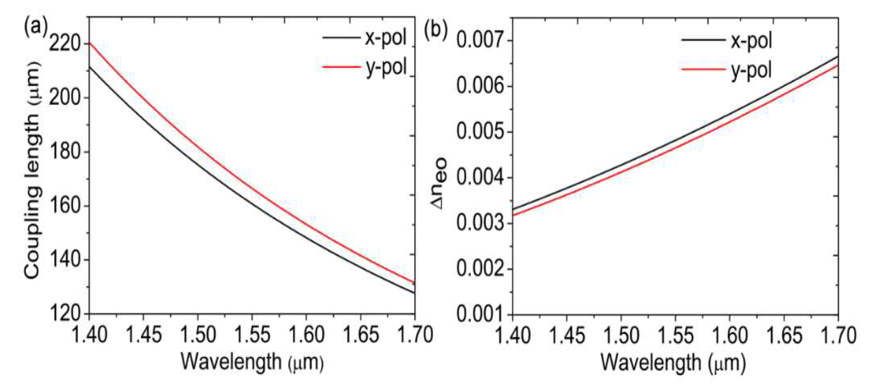
According to Eq. (3), it is determined that there is a wavelength link between supermode coupling length and refractive index.
Figure 5(a) and
Figure 5(b) depict, respectively, how coupling length and refractive index difference change with wavelength. At 80 Oe, the magnetic field’s strength is determined. The discrepancy in
’s refractive index grows as wavelength increases. The coupling lengths thus shorten in both orthogonal directions. Moreover, the coupling length in the y-polarization direction is more significant than in the x-polarization direction.
According to Eqs. (4) and (5), the transmission spectrum is correlated with both the DC-PCF length and coupling length. Since 1.55
m is usually the communication wavelength, many devices are designed at 1.55
m. Moreover, we use 1.55
m as the reference wavelength.
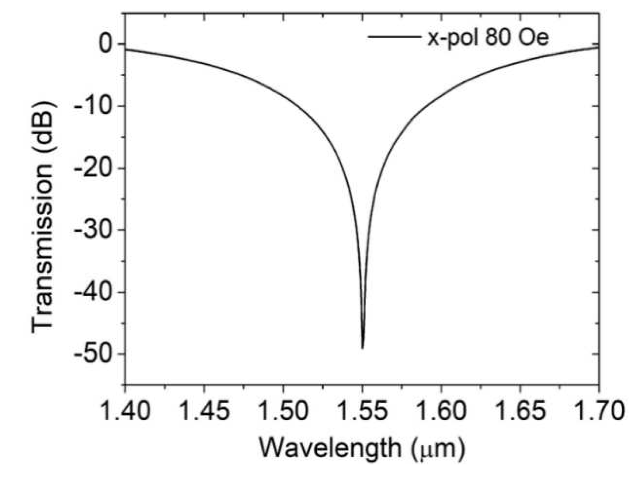
Figure 6 displays the transmission spectrum in the x-polarized direction. The DC-PCF length and magnetic field are set as 482
m and 80 Oe. A visual trough is formed at the 1.55
m communication window. Then, the magnetic field sensing characteristics of the DC-PCF are analyzed theoretically.
As the magnetic field intensifies, the refractive index of the MF rises. The refractive indices of the supermodes differ correspondingly.
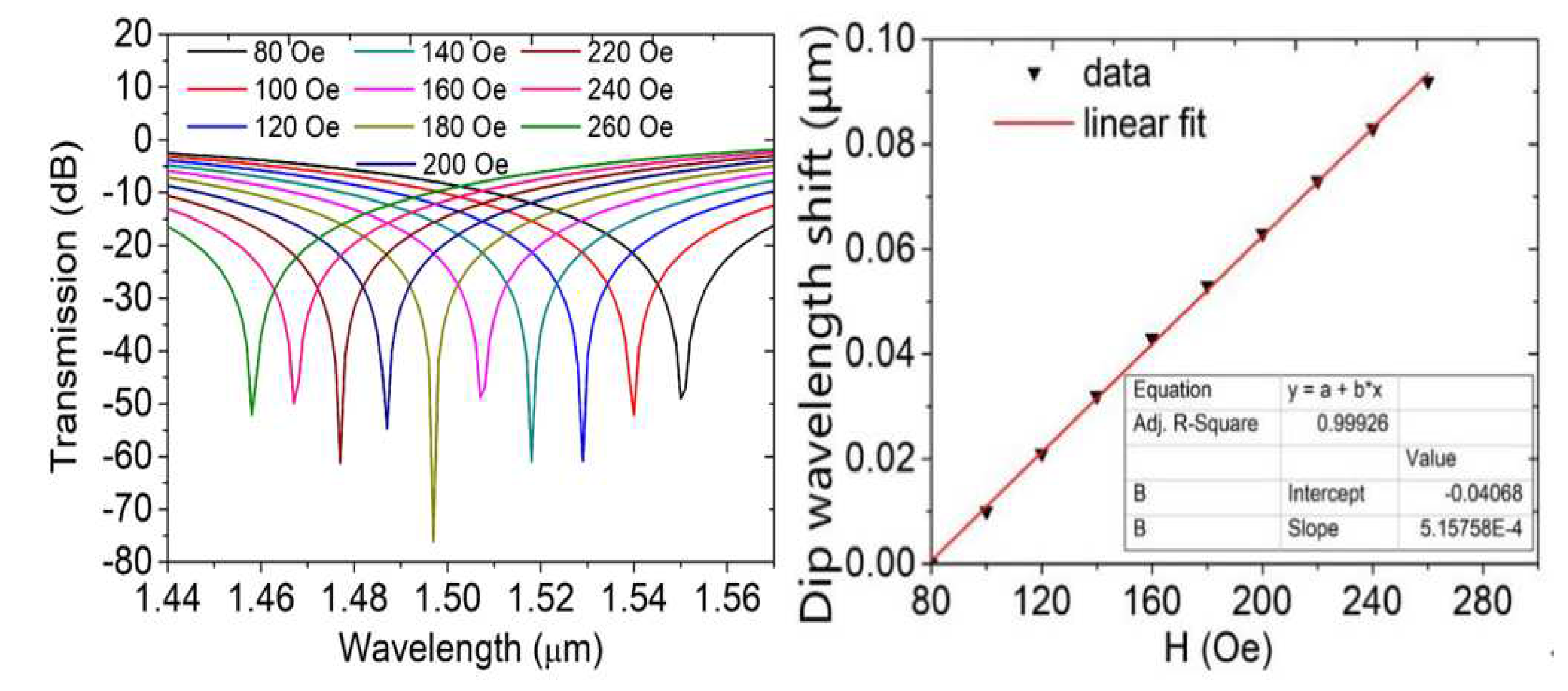
Figure 7(b) shows variations in dip wavelength shift with the magnetic field and
Figure 7(a) transmission spectra at various magnetic field intensities. The dip wavelength moves toward the blue end of the spectrum from 80 to 260 Oe of magnetic field strength. Because of this, the coupling wavelength is sensitive to variations in the strength of the magnetic field, and the strength of the external magnetic field can be estimated by measuring the coupling wavelength in the transmission spectrum.
As seen in
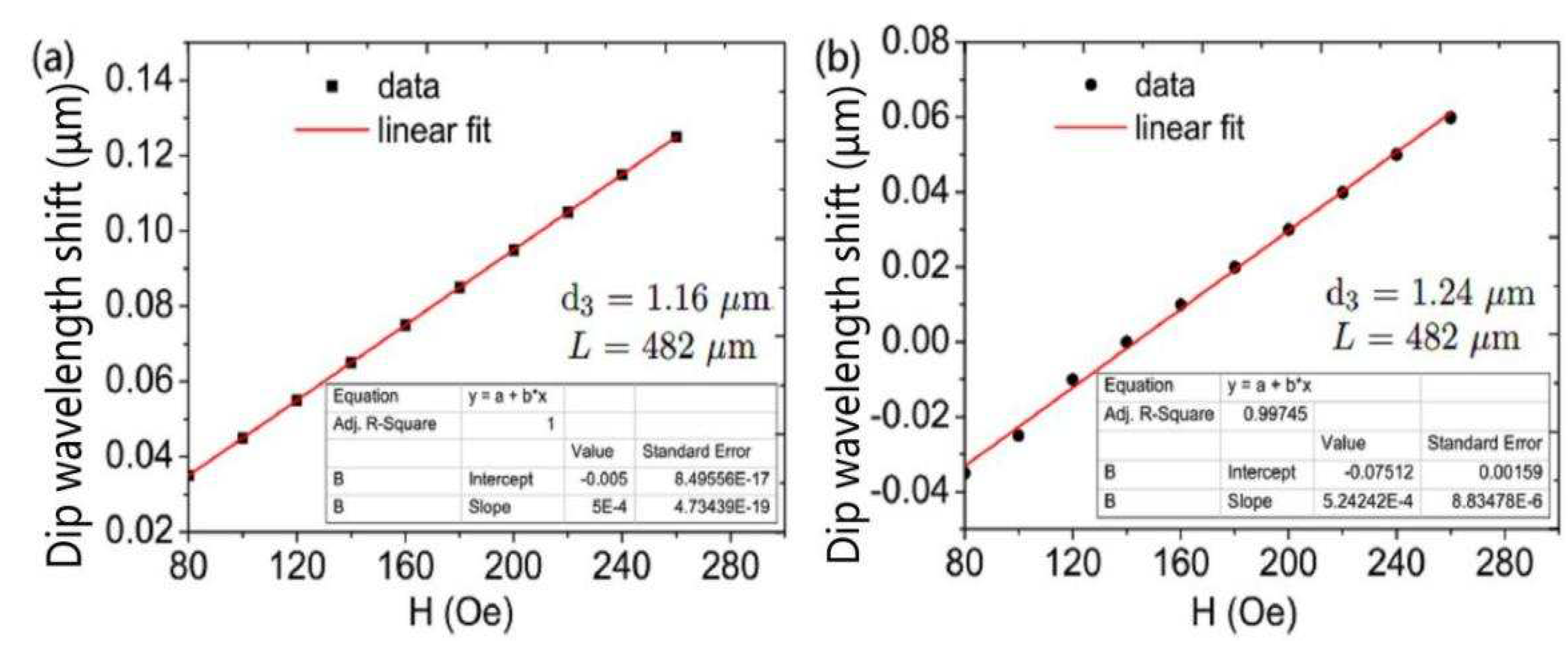
Figure 7(b), there is a linear relationship between the coupling wavelength and the strength of the magnetic field. The relation curve of the two is fitted, and the slope and fitting variance can be obtained. The physical meaning of the slope is the DC-PCF magnetic field sensor’s sensitivity, and the sensor’s sensitivity is 515.75 pm/Oe. The magnetic field strength and the coupling wavelength exhibit a strong linear relationship, as shown by the fitting variance of 0.99926. It offers many benefits and lowers the measuring error of magnetic fields as a magnetic field sensor. We generated and examined the transmission spectra at various structural parameters to investigate the impact of the PCF’s structural factors on magnetic field detection performance.
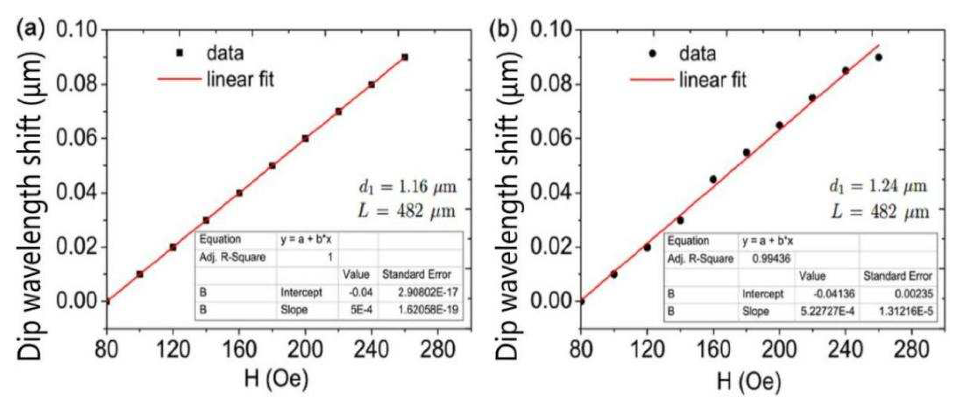
Figure 8 shows the variation in the shift of dip wavelength with the magnetic field at different diameters d
. The DC-PCF length has been adjusted at L=482
m. When d
increases, the discrepancy between the effective refractive indices of the four supermodes and those indices also decreases. The coupling length lengthens as d
rises. The slopes of the curves determine the sensitivity of the magnetic field intensity sensor. The simulation results demonstrate that the magnetic field intensity sensor’s sensitivity increases as diameter d
grows. The sensitivity of the magnetic field sensor is 500, 515.75, and 522.72 pm/Oe as d
is 1.16, 1.20, and 1.24
m, respectively, as can be seen by comparing
Figure 7(b) and
Figure 8. As d
rises, the sensitivity rises as well. An increase in coupling length enhances the interaction between the transmitted light in the fiber cores and the magnetic fluid, increasing sensitivity.
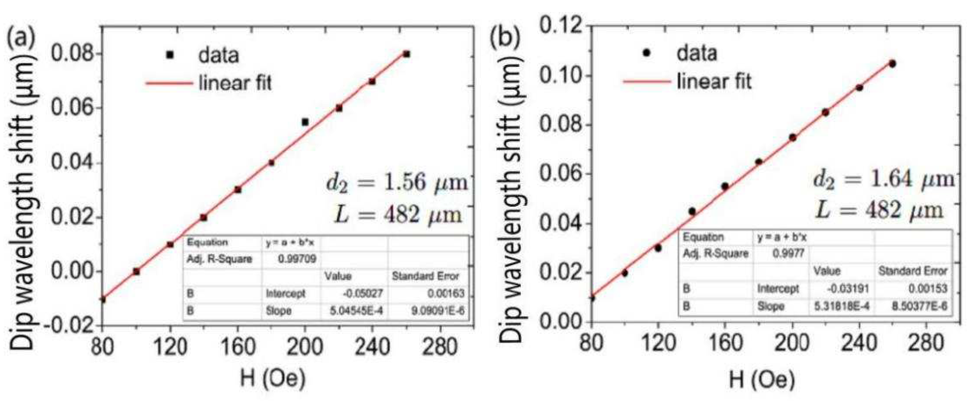
Dip wavelength shift varying with magnetic field intensity at different diameters d
is shown in
Figure 9. DC-PCF length is set as L= 482
m. The difference between the effective refractive indices of the supermodes increases as the effective refractive indices of the four supermodes decrease as d
increases. As a result, the coupling length shortens with increasing d
, and a blue shift in the wave trough is seen. The sensitivity of the DC-PCF sensor greatly rises as the diameter d
rises from 1.56 to 1.64
m, as can be shown in
Figure 9 and
Figure 7b. The sensitivity is 504.54, 515.75, and 531.81 pm/Oe for d
=1.56, 1.60, and 1.64
m, respectively. The transmitted light in the core is first compressed as d
rises, enhancing the sensitivity and mode coupling strength.
The dip wavelength shift is shown in
Figure 10 as a function of the magnetic field strength at various d
diameters. The length of the DC-PCF is fixed to L = 482
m. As d
is the hole that magnetic fluid fills, as d
increases, so does the magnetic fluid region. When d
increases, there is a decreasing disparity between the effective refractive indices of the four supermodes and their combined effective refractive indices. The coupling length lengthens as a result, the wave trough undergoes a red shift, and the sensitivity is improved. As d
= 1.24
m, the sensitivity increases to 524.24 pm/Oe.
Table 1 shows the comparison of MF and fiber-based magnetic field sensors. Many sensor types, such as birefringence interference [
22], Mach-Zehnder interference [
23,
25,
26], Fabry-Perot interference [
24], Sagnac interference [
27,
28], surface plasmon resonance [
28], and directional coupling [
10], have been used to detect the magnetic field. Some of the magnetic field sensors [
24,
27]did not have a linear responses which reduces the accuracy of the sensor and limits their applications. Due to the strong absorption of light by magnetic fluid, the optical signal will be feeble when light reflects from or passes through the magnetic fluid [
10,
23]. Our proposed magnetic field sensor used the directed coupling in MF-filled DC-PCF. A linear response of 80-260 Oe was used to attain the high sensitivity of 524.2 pm/Oe.
Author Contributions
Conceptualization, Y.L., L.Z., and S.R.; writing—original draft preparation, Y.C., R.Z., P.C., L.Z., H.C.; and writing—review and editing, Y.L., H.C., L.Z., R.Z, P.C.and S.R.; All authors have read and agreed to the published version of the manuscript.
