1. Introduction
The research does not stop on the possibilities on the use of the Polyether-ether-ketone (PEEK) polymer, as a biomaterial for the development of custom-made bone prostheses and other types of applications in the field of medicine; since it has been proven to be an ideal replacement for metallic materials such as titanium and its alloys, and polymers such as Polymethylmethacrylate (PMMA). The advantages of PEEK revolve around its lightness, its modulus of elasticity close to that of natural bone and its good biocompatibility. If the biological, mechanical and manufacturing properties of the PEEK are compared with the above mentioned materials the PEEK has supremacy at the moment.
For example, in [
1] a study carried out with 45 patients with unilateral post-traumatic defect of the orbital wall, who received subsequent treatment with personalized reconstruc tions with PEEK, or with pre-bent titanium plates, is reported. The patients were divided into two groups, the obtained results showed that there was no infection, no inflammation, nor decreased vision in any of the groups. On the other hand, diplopia did not appear in 82.1% of the patients treated with PEEK, compared to 70.6% of those treated with tita-nium (control group). The mean surgery time was 54.25
± 16.8
min with the application of personalized PEEK-based implants, compared to 82.9 ± 10.8
min for the control group. The mean difference between intact and damaged orbital volume was 1.9 ± 1.4
cm3 in the control group versus 0.74 ± 0.6
cm3 in the PEEK group (
p < 0.05). Thus, the best results were obtained for PEEK in terms of restoring the volume and shape of the damaged orbit.
In [
2], is presented a comparison between properties of PEEK elements printed in 3D applying Fused Deposition Modeling (FDM), and elements milled with the same material. The surface treatment technique used yielded better results (elimination of manufacturing defects and roughness for better cell adhesion and distribution in 3D printed devices). In addition, no toxicity was observed in the subsequent 48 hours, during the evaluation of adhesion assessed by the cultivation of primary human endothelial cells and osteoblasts. On the other hand, considering the limitations of PEEK due to its bio-inertness, hydropho-bicity and susceptibility to microbial infections, in [
3] is reported on the review of somemodification strategies, such as the superficial one and the incorporation of materials in the base matrix, which can increase the biological activity of the material and its antibacterial and bio-active performance. Another promising approach, regarding the improvement of the surface bio-activity of custom 3D printed PEEK implants by fused deposition, is reported in [
4]. The authors of this research obtained encouraging results by immersing the material for two minutes in concentrated sulfuric acid to obtain the so-called sulfonated PEEK.
From the point of view of design and bio-mechanics, studies have been carried out on the behaviour of human bones manufactured from PEEK; finding similarities between the mechanical response of the artificial element and that of the natural one [
5]. Fracture mechanisms have been revealed and the material’s response to prolonged exposure to high temperatures has been studied [
6]. The authors of [
7] design micro-structures with PEEK and its compounds to improve implant compatibility. A homogenization process is carried out, controlling the isotropic lattice structure, with the help of reduced graphene oxide (rGO) and calcium hydroxyapatite (cHAp). With the improved design it is possible to eliminate light imperfections, increasing the stability of the structure. The controlled homogenization, porosity, and particle size distribution help increase cellular infiltration and biological integration of the PEEK, rGO and cHAp compounds.
Regarding the manufacturing techniques that are most applied, 3D FDM printing predominates. The authors of [
8], show the supremacy of the 3D FDM technique over subtractive manufacturing processes such as Computerized Numerical Control (CNC) milling, and show results achieved at the University Hospital of Basel, despite the diffi- culties involved in the medical certification of this workflow. Likewise, in [
9], the first 3D printed scaphoid prosthesis is described, at the Cantonal Hospital Baselland, Switzerland, using medical grade PEEK with fused filament manufacturing (FFF) technology. This same technique is analyzed in [
10], and the favourable temperature conditions during 3D print- ing are highlighted, compared to processes such as selective laser sintering and injection moulding. 3D printing overcomes many of the restrictions of other related techniques and allows to offer better solutions that are structurally adapted to the needs of the patient. Then, in [
11], the process of solving a defect in cranioplasty caused by a deficiency of the titanium mesh used initially is described, which weakened the arch of the left eyebrow and caused a deformation of a sinus path. The problem was corrected by applying an additively manufactured cranial implant with PEEK for the new cranioplasty.
In [
12], it is reported on experimentation with PEEK sheets, manufactured by Single Point Incremental Forming (SPIF), which is a flexible and matrix-free forming technology that allows complex shapes to be obtained. In addition, it is of great economic profitability in reduced production. The results of the SPIF tests allowed the development of analyses in terms of formability, failure modes, temperature, forming force and geometry precision; and thus, evaluate optimal parameters and methodologies for the manufacture of prosthe- ses. All the above allowed us to verify the potential of manufacturing personalized medical devices through incremental sheet formation (ISF) processes in combination with advanced biocompatible polymers such as PEEK.
Many reports have also been published on the results of the application of surgical techniques and intervention planning, and follow-up of implanted patients. For example, in [
13], the evolution of six patients operated on for intraosseous meningiomas is reflected. The resection strategy was planned and discussed with the manufacturer of the custom PEEK bone implant used in the reconstructive phase. The authors of the paper state that
“the described technique is simple, precise and effective to achieve good results in disease control, as well as in aesthetic and functional restoration”. In [
14], is described a patient in whom a PEEK implant was applied as a solution for the remodelling of the skeleton and soft tissues in facial aesthetic plastic surgery. The surgeons thus responded to the patient’s complaints about hypoplasia of the malar area, after three operations of placement and replacement of silicone implants. The person expressed dissatisfaction regarding the symmetry and sensation through the skin of the lower eyelid, at the edge of the prostheses. After the application of the PEEK variant, no complications were reported and the results seem to be satisfactory for both parties.
A very complete summary of the benefits and potential of PEEK has been published by Abid Haleem and his collaborators in a letter to the Editor [
15]: the material in question is suitable for artificial bone replacements because it is biocompatible, non-toxic, and non-inflammatory and osteoconductive. Its low molecular weight makes it ideal in orthopaedics for fracture fixation and osteotomies, spinal fusions, and ligament reconstructions. Its high resistance provides it better mechanical properties compared to other traditionally used materials, since it supports the loads generated in the human body. It also helps to evaluate the evolution of fractures, thanks to the fact that it is radiolucent in radiographs. And it is compatible with Computerized tomography (CT) and Magnetic resonance imaging (MRI) technologies, that is, PEEK does not interfere with these imaging techniques. Before the appearance of PEEK, another polymer used in this type of surgical proce-dure and treatment of bone conditions was PMMA. In the review article [
16] a section is dedicated to the comparison between both materials, in terms of advantages and disadvan-tages in implantology applications. As for PMMA, it polymerizes through an exothermic reaction that can be harmful to overlying soft tissues [
17]. Implants based on this material cannot be infiltrated by new bone tissue due to its lack of porosity, it interferes with os-teoconduction and vascularization, it does not interact with the surrounding tissue, and it may be susceptible to higher infection rates ([
18,
19,
20,
21]). On the other hand, four studies ([
22,
23,
24,
25]) report similarities between PEEK and PMMA in terms of the success rate of treatment and rate of complications.
This paper reports on a planned and materialized cranioplasty with PMMA in a health institution in southern Ecuador. And as part of the investigation, the performance of the customized bone implant, manufactured with PEEK and with PMMA, is compared at the level of simulation of the mechanical response. This considering the advantage of PMMA over PEEK in terms of cost. A random internet search found the value of PMMA to be between USD 1.99 and USD 3.80 per kg. While the price of medical-grade PEEK resin is between USD 1450 and USD 1470 per kg. A limitation of PEEK technology is the requirement for support structures, which incurs additional costs. Considering the above, and that the average purchasing power of the inhabitants of this area is low, the PMMA-based variant of implants remains a viable option for many people who do not have the necessary resources to afford the best PEEK-based solution.
2. Materials and Methods
2.1. Data Acquisition Medical Imaging and Segmentation
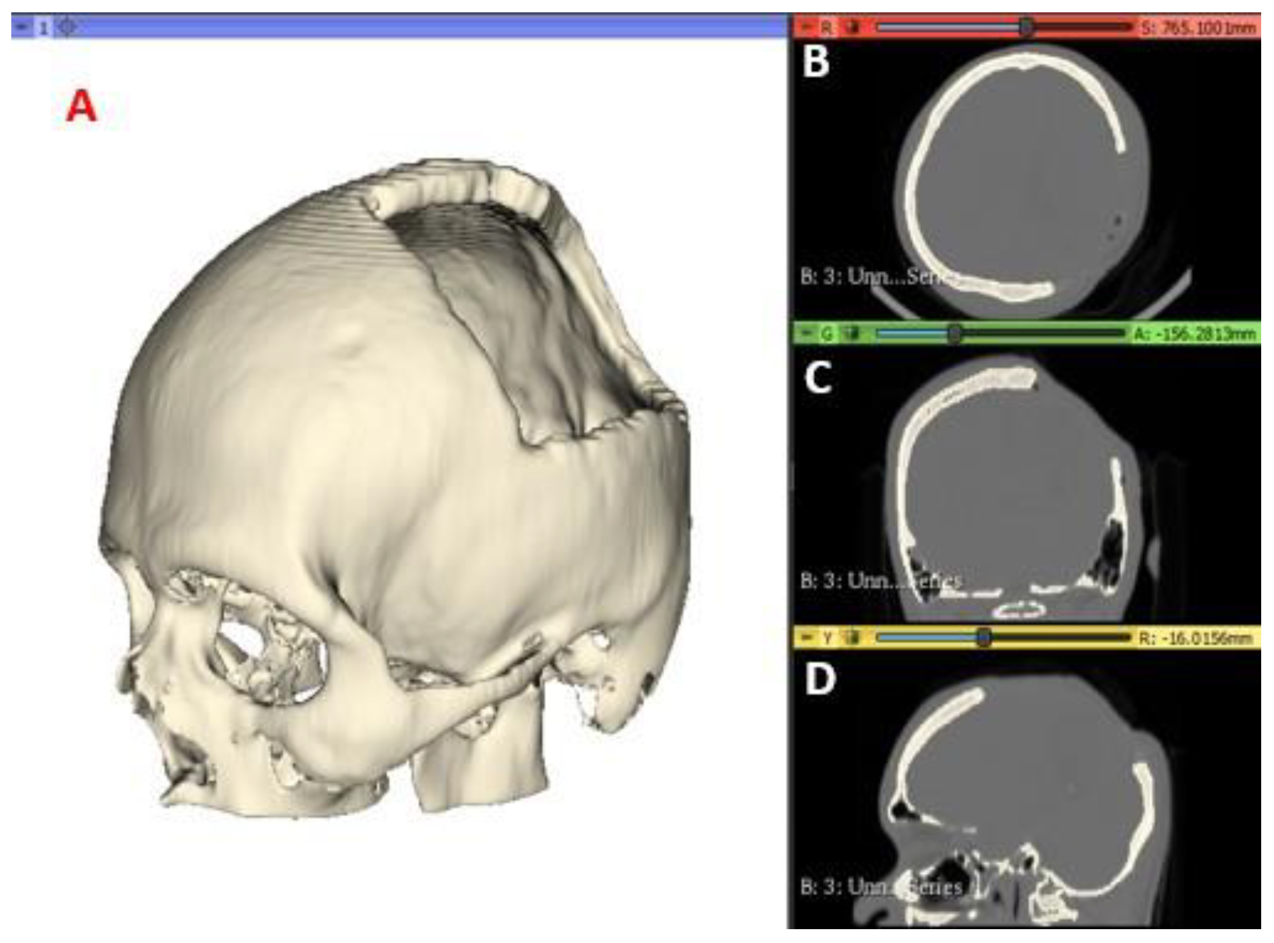
A computed tomography of the patient was performed, and the images were saved in a high-resolution Digital Imaging and Communications in Medicine (DICOM) file, with voxels of 512 × 512 ×
Z, where
Z varies from 150 to 520 slices. The images were then pro-cessed using the open-source software
3D Slicer (
https://www.slicer.org) to generate the Standard Tessellation Language or Stereolithography (STL) file of the anatomy of interest. The tomographic images were segmented with a specific intensity, called Hounsfield Unit (HU), which measures the attenuation coefficient on the grey scale for compact tissues, in this case of the target anatomical region of the patient. For the present study, values of 211.73–2755.0 HU are used to segment the cranial compact bone model. In
Figure 1 the medical images and segmentation are shown.
2.2. Finite Element Method
2.2.1. Cranial Model
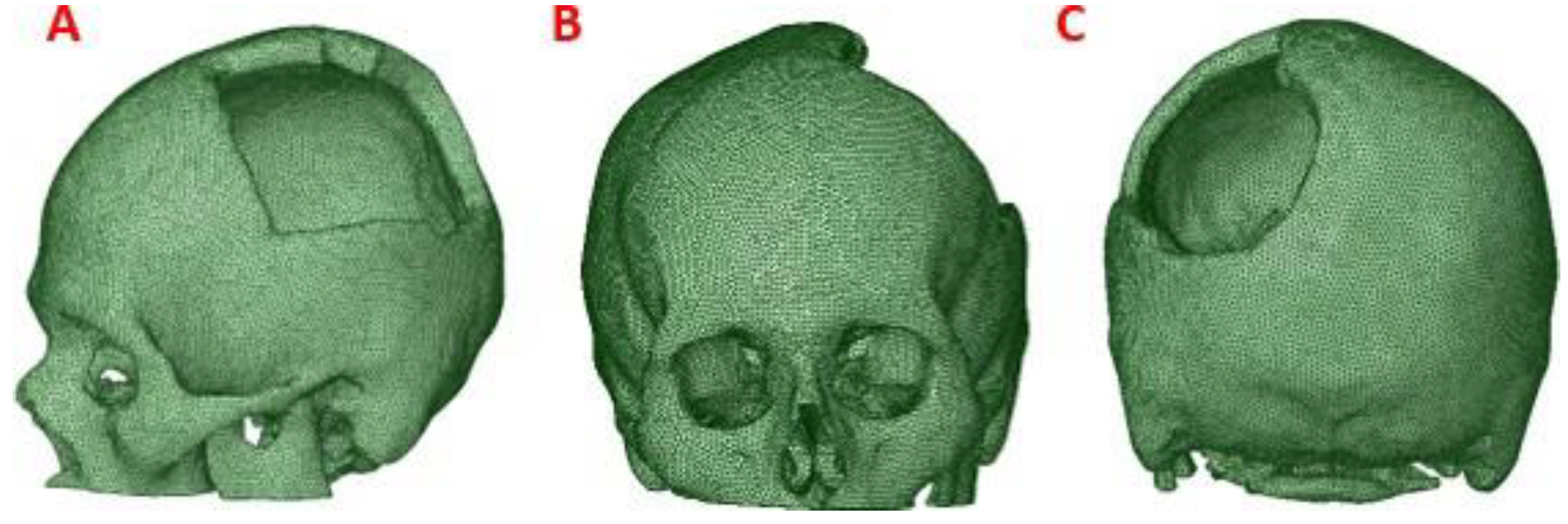
To obtain the three-dimensional geometry of the patient’s cranial model, the STL file was processed by treatment of meshes and cloud of points, with reverse engineering tools provided by the
Autodesk Meshmixer software (
https://www.meshmixer.com), and Ansys Workbench.
This process was applied to the anatomical model of the patient to obtain a precise 3D model of his anatomy, which was then used for finite element analysis (FEM). (
Figure 2)
2.2.2. Customized Implant Model
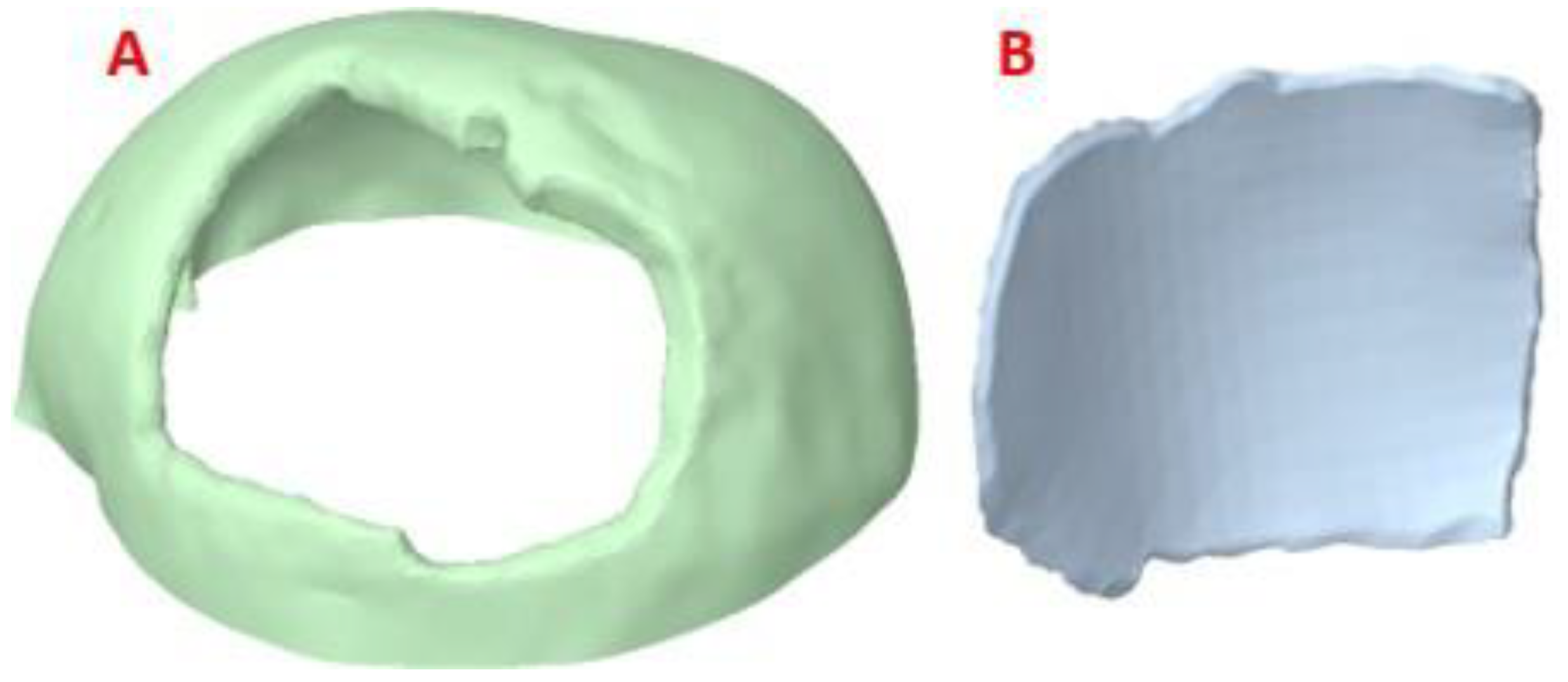
The post-processed model of the skull with the defect was used for the reconstruction with the cranial implant, using the
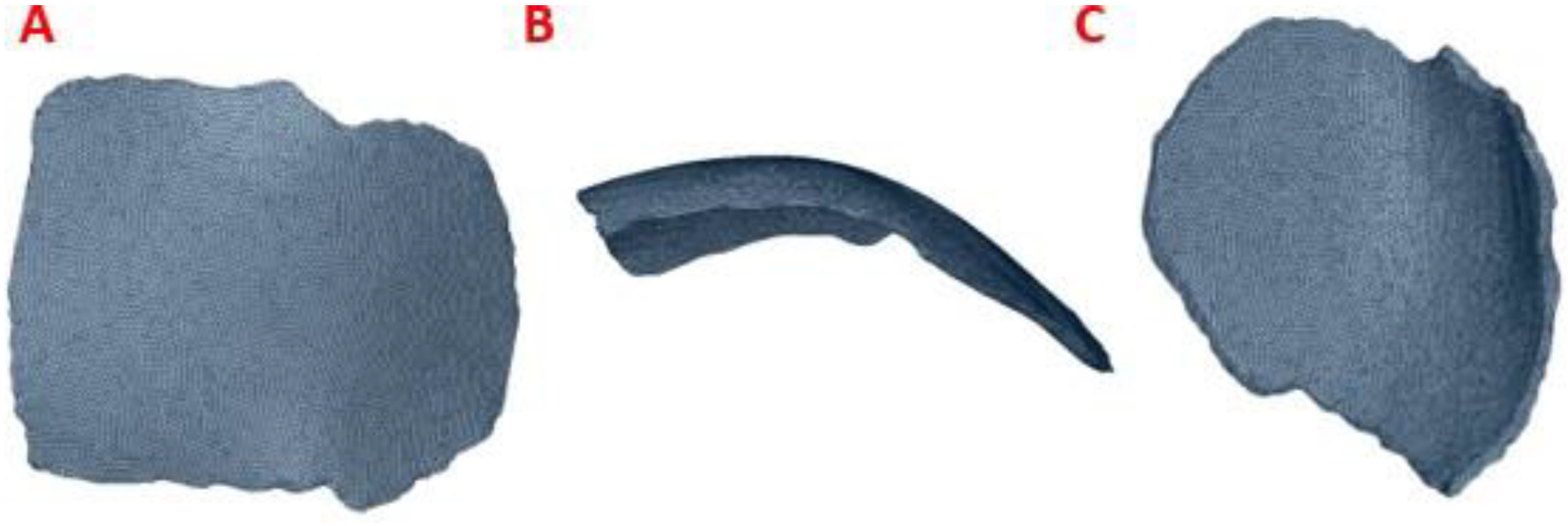
Autodesk Meshmixer software. A symmetrical reference plane was created in the three-dimensional model. For the restoration of the affected area (missing cranial bone), the structural symmetry of the human body was assumed. With the editing tools of the software, the healthy side of the structure is inverted, creating a mirror image that can be superimposed on the area to be restored. Both parts of the structure are assembled to fill the cavity. Subsequently, the Boolean subtraction tool is applied to obtain the required custom implant design (
Figure 3).
2.2.3. Assembly of the Skull Model and Medical Device
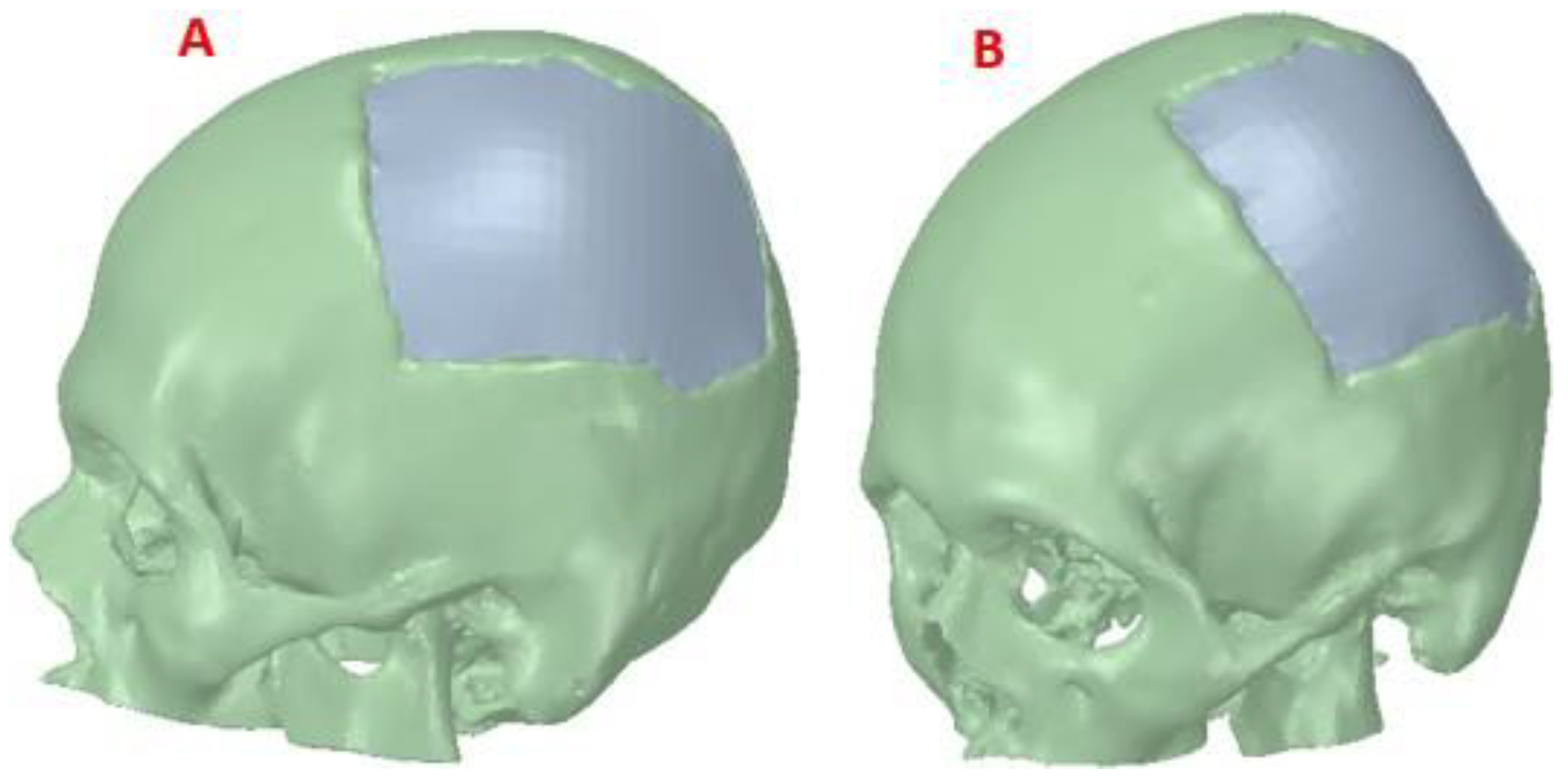
Figure 4 shows the reconstructed cranial model of the patient. The design of the implant was carried out in a personalized way, and when the person receiving the medical device requires it (in extreme cases), this model is also useful for simulations. For example, in high-performance sports activity, failures of implanted medical devices have been evi- denced, causing structural and physiological damage to the bone. An adequate simulation study can contribute to the determination of the mechanical parameters that personalized medical devices must present to be able to withstand certain static loads, also simulating events that may take place during the performance of these types of activities [
26].
For the simulation studies in this case, the materials used for the computational analy-sis were two: one of low cost, widely used in operating rooms for immediate cranioplasties, and in the dental sector, PMMA. And the second, of high performance and high cost, although with better biocompatibility properties, industrial grade PEEK, is used in Latin American countries for medical purposes.
2.2.4. Coupling Details
For the successful fixation of the implant, it is important to detail the interface contours of the cranial profile, and the location of the implant. For this, the perimeter area of the damage is studied and how the stress transfer occurs under considered external load con-ditions. In the article [
27] the relevance of analyzing the contacts of natural bone-implant interfaces is highlighted, in addition, its authors corroborate that the edges of the defect must have a surgical preparation at positive angles, while the edges of the device to be implanted must have opposite angles, in such a way that the “fit” will be the best possible, thus contributing to the coupling safety.
If the implant does not have support on the cranial bone, in the presence of external loads, stresses are transferred to the fixing elements, which endangers the integrity of the system. High stresses would potentially compromise the bone morphology required for anchorage. For the case reported in this paper, the fixation systems were not analyzed since full support of the implant was achieved on the cranial damage perimeter. (
Figure 5)
2.2.5. Boundary Conditions
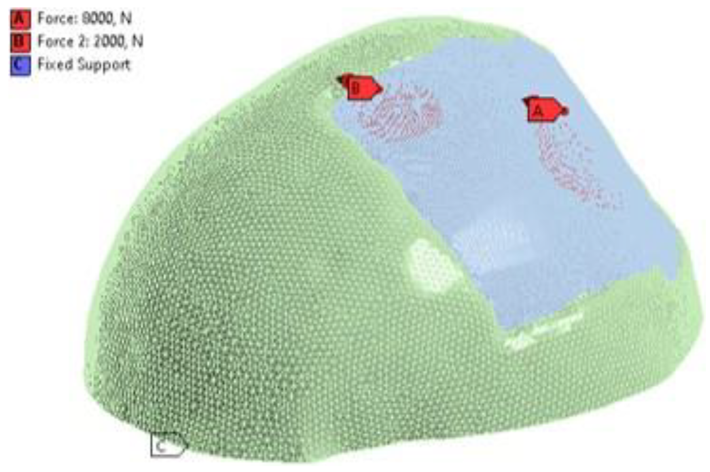
For the analysis using the finite element method, the structural static modulus was considered. The established loading conditions were assigned to the external surface of the implant. An external load of 8000
N was applied to the centre of the implant [
28], which simulates the static load of a collision with some foreign object. And a 2000
N load was also applied to the top left of the implant, simulating what happens during rest.
For reducing the computational load in the simulation, the cranial model was adjusted in such a way that the number of mesh elements was reduced, and the simulation time decreased. An embedment condition called “Fixed Support” was also assigned at the base of the axial slice of the skull with zero displacements and rotations (
Figure 6).
2.2.6. Mesh Conditions
The simulation was carried out with the help of the
ANSYS WORKBENCH R21.1 software (ANSYS Inc., Canonsburg, Pennsylvania, USA). The selected mesh was made up of tetrahedral elements (SOLID185). The mesh refinement tests yielded a 7% convergence guarantee. The model is composed of 329898 nodes and 178488 elements of size 5
mm. “Bonded contact” was also considered for border conditions at the implant-cortical bone interface, the most realistic according to [
29]. Details of the mesh can be seen in
Figure 7.
2.3. Material Properties
In the computational model, the materials were assumed to be isotropic, homogeneous and linearly elastic, by [
30,
31]. The custom medical device was made of PMMA and PEEK.
Table 1 presents the mechanical properties of each material used in the simulations.
Once the mechanical properties of the components were introduced, FEA simulations were carried out to study the behaviour of the cranial model under external static loads, which are useful to understand how the stresses are distributed in the cranial area during the performance of the considered activities.
2.4. Surgical Planning and Manufacturing
In the manufacture of the anatomical test model, for surgical planning, the additive manufacturing technology Fused Deposition Modeling (FDM) was applied, with the help of a
Creality CR-X Pro 3D FDM printer (Shenzhen Creality 3D Technology Co., Ltd.). As printing material, Creality’s HP PLA 1.75
mm Series filament was used. The STL file was used as the basis for reading, processing and obtaining the route code, while for the 3D printing process, the
Creality Slicer 1.2.3 software was used. The support material was removed manually, paying special attention not to affect the surface of the bone structure.
Table 2 presents the characteristics of the FDM technology. 233
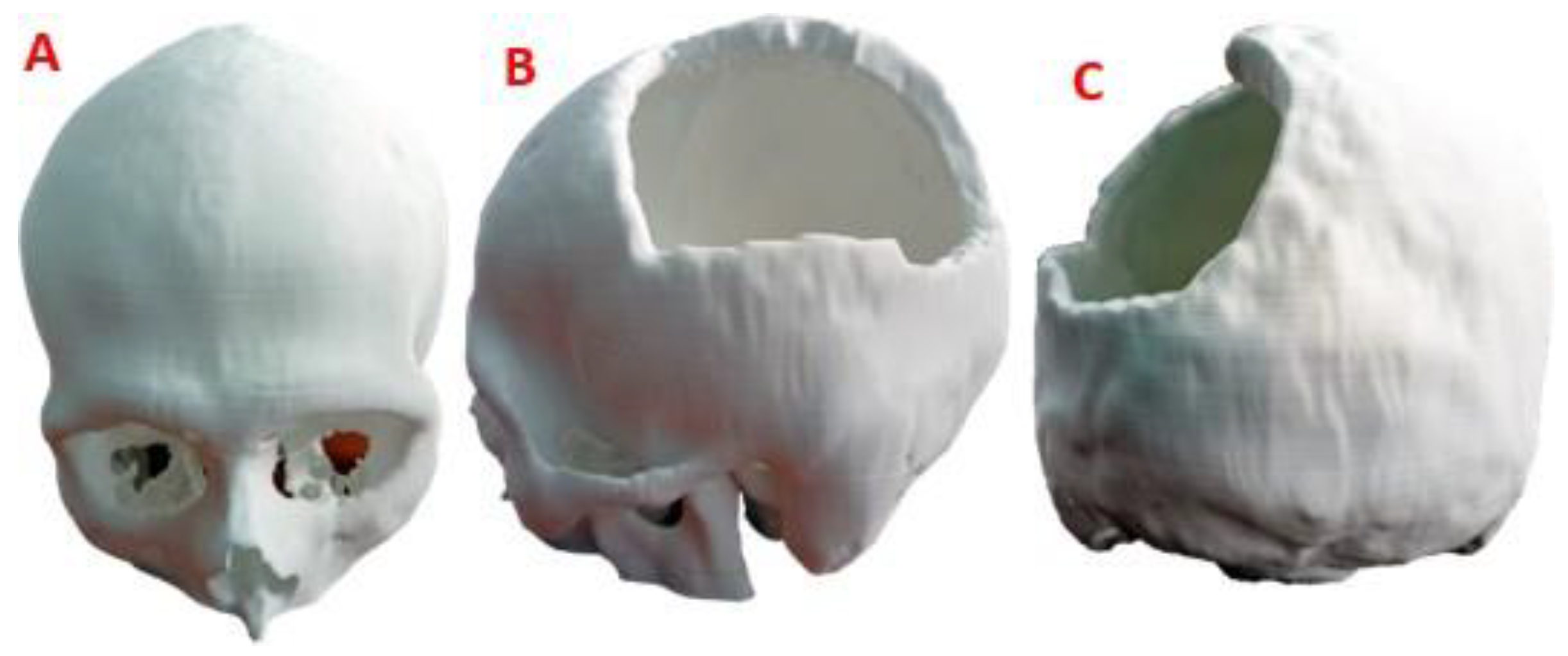
The 3D version of the test anatomical model, printed on a 1:1 scale, can be seen in
Figure 8. The level of damage in the left parietal area of the patient is considerable, so the results of the finite element analysis offer the necessary support for the medical device to withstand demand loads.
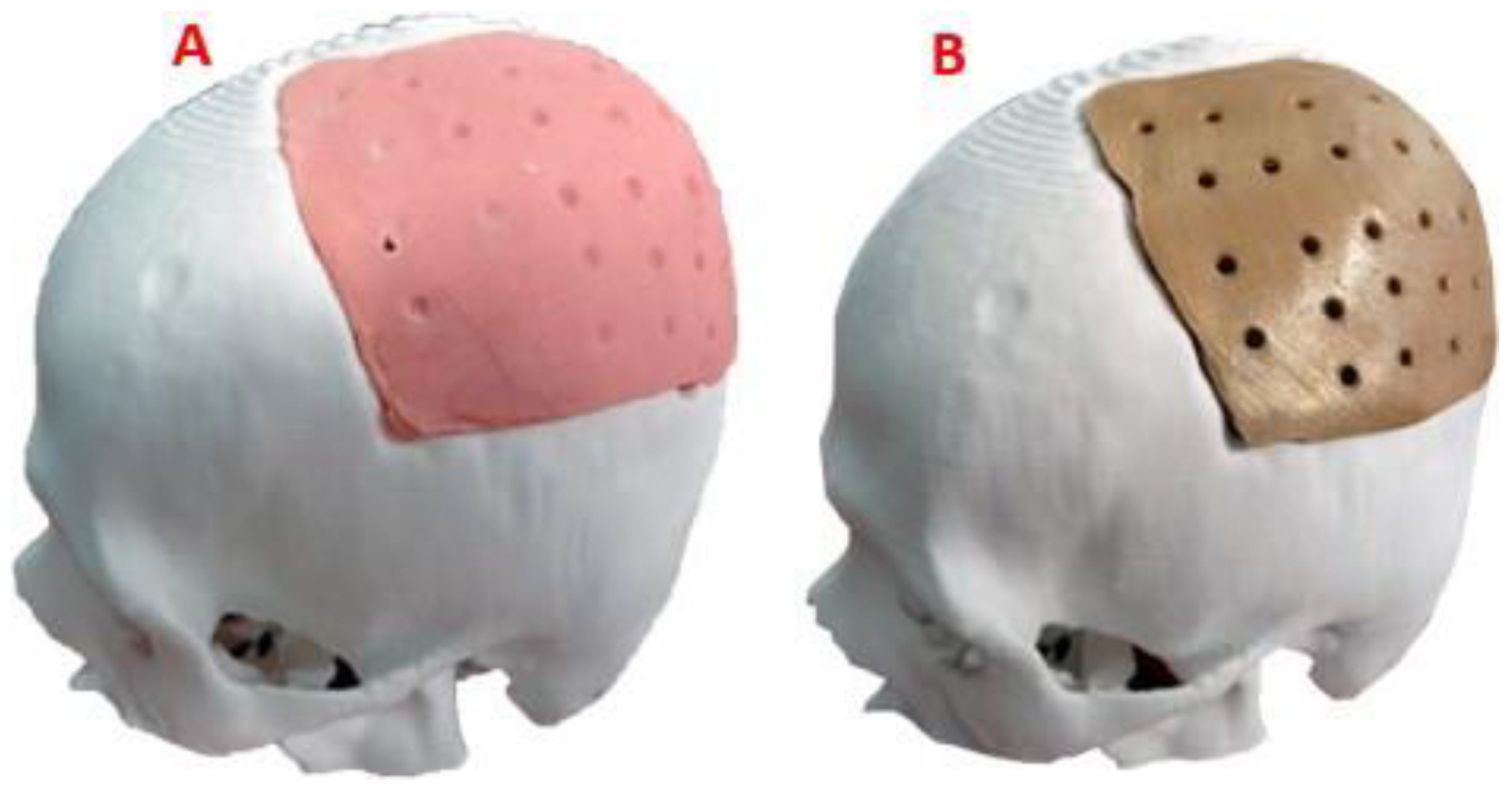
The trial anatomical model was used by the surgeon in the preoperative evaluation and surgical planning, thus verifying the functionality of the customized device. The test model of the customized implant was also used to obtain a sterile mold of thermosetting material, with which the final PMMA-based implant was made. For its part, the customized implant model, in industrial PEEK, was manufactured with the help of a
FUNMAT PRO 410 printer, applying FFF additive technology. Subsequently, the definitive test of the implant was carried out on the cranial anatomical model and it was verified that the shape was consistent with the virtual models (
Figure 9).
3. Results
Four simulation cum-shots were performed under the “Force” load condition of 2000 N applied to the external surface of the cranial bone-coupled PMMA-based custom implant model, and with the same condition applied also on the external surface of the personalized implant model based on PEEK coupled to the cranial bone. The geometry of the personalized implants, for both materials, presents variable thicknesses. Towards the central point, where the 2000 N load was applied, the thickness is 2.58 mm; while at the point where the 8000 N load is applied, the thickness is 3.02 mm.
Likewise, for the load condition “Force” of 8000
N applied in the central zone of the external surface of the model of the personalized PMMA implant, coupled to the cranial bone. And the same load condition was applied to the central area of the external surface of the custom PEEK implant model, coupled to the cranial bone. This allowed us to obtain the von Mises stress distribution for the implant and the cranial bone, and the total deformations (
Table 3).
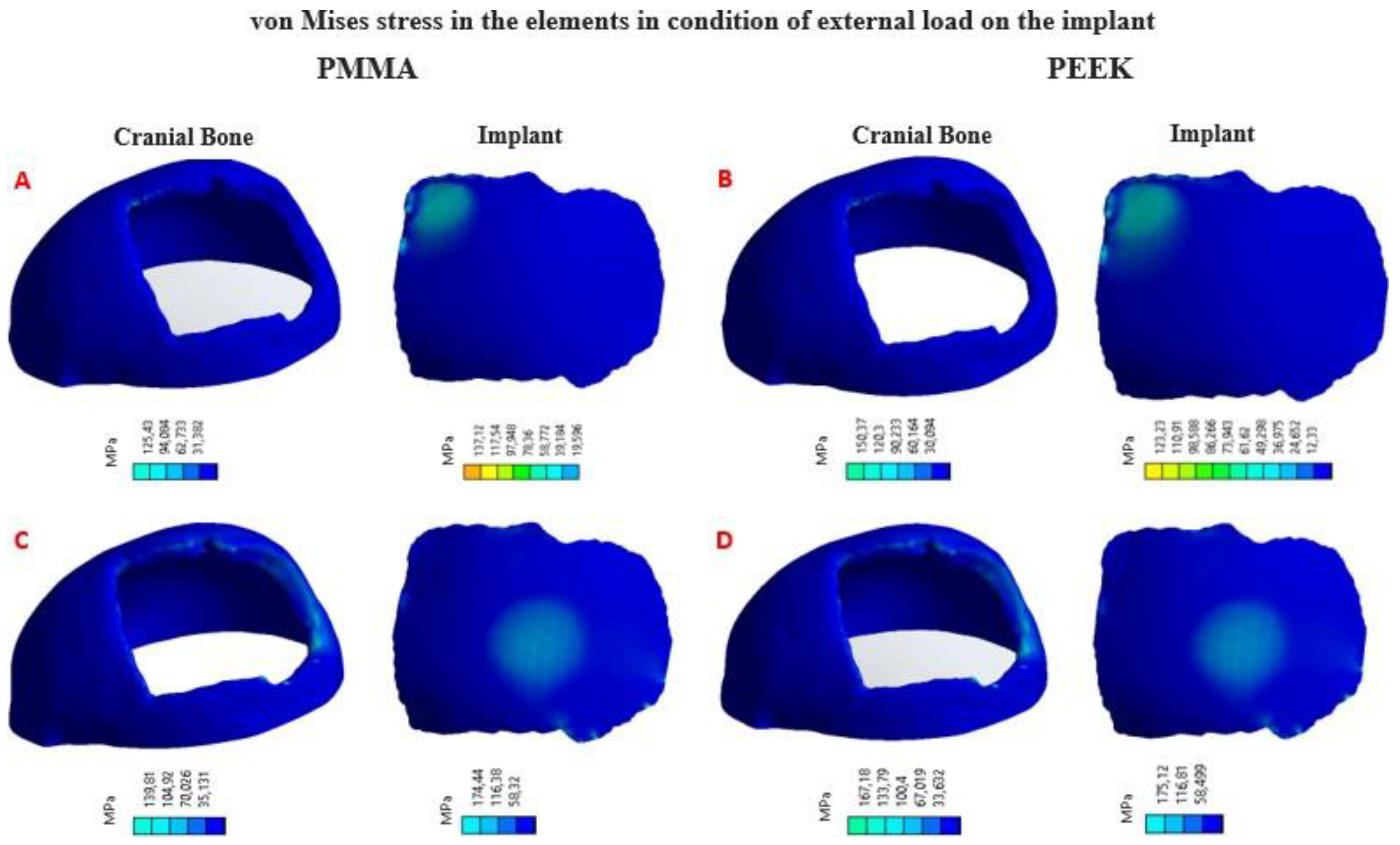
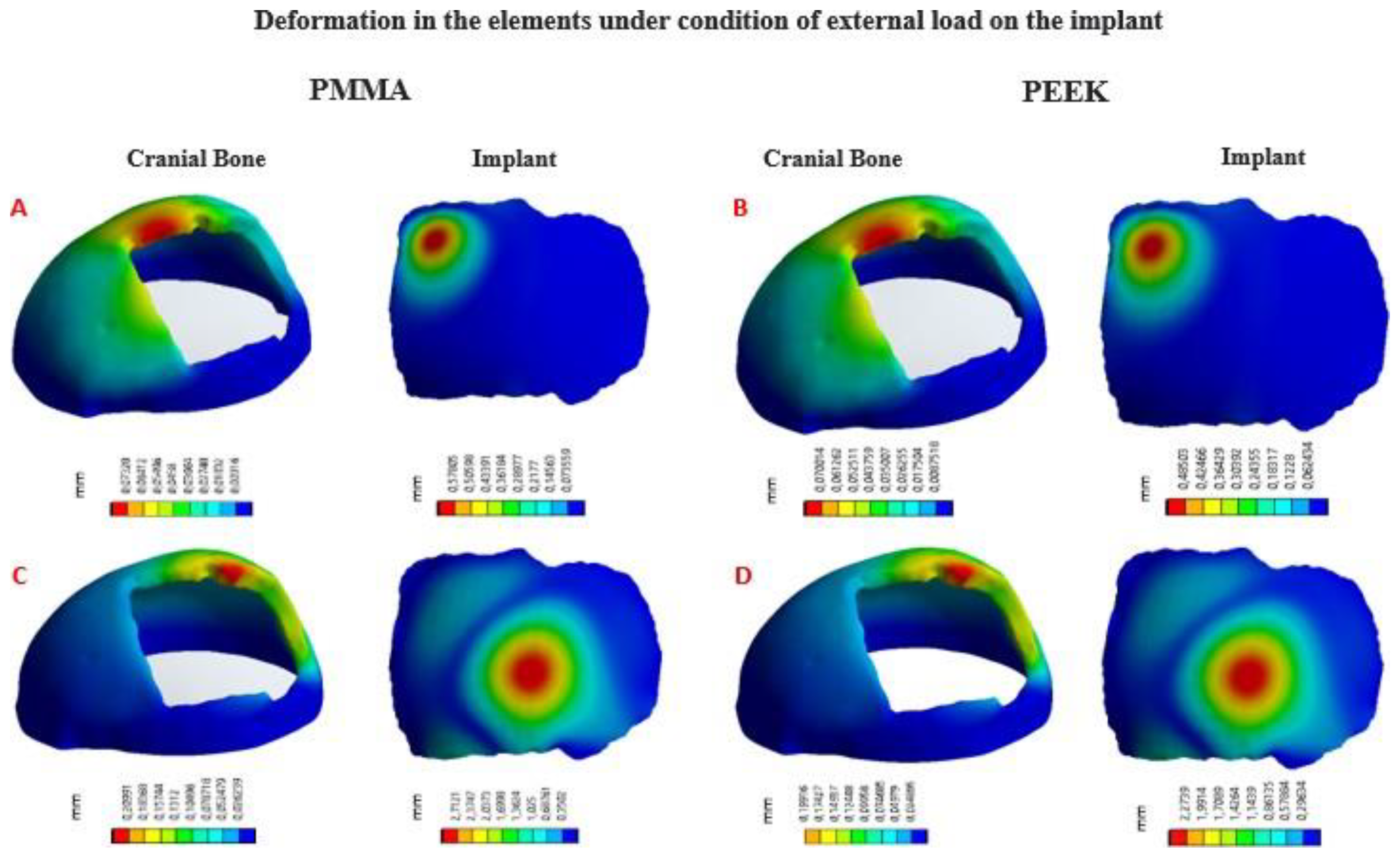
In
Figure 10, the von Mises stress distribution for each element can be seen, according to the state of external load. In
Figure 11, the total deformations generated by the states of external loads, in the implant and the cranial bone, are detailed.
3.1. Statistic Analysis
The statistical analysis of the computational results was carried out by applying the analysis of variance of one factor (ANOVA), with the help of the
SPSS Statistics software (SPSS, Inc., Chicago, IL, USA). In
Figure 12 (A), the von Mises stress levels for the per- sonalized implant with PMMA and PEEK are observed.
Figure 12 (B) shows the total deformation of the implant with each material under the load condition “Force” 8000
N.
In this computational study, the effect of using PMMA and PEEK for the protection of the skull against the action of a static load of 8000 N on the surface of the device was examined. The mean and standard deviation of the von Mises stress analysis for the PMMA implant was 103 ± 20 MPa; while for the PEEK implant, it was 99± 11 MPa. In this case, no significant differences are observed (p > 0.05), with a confidence level of 95 %.
The total deformation of the PMMA implant was also examined, where the mean and standard deviation of the analysis were 2.71 ± 0.22 mm; while for the PEEK implant, 2.30 ± 0.03 mm was obtained. In this case, significant differences were observed (p < 0.05), with a confidence level of 95 %.
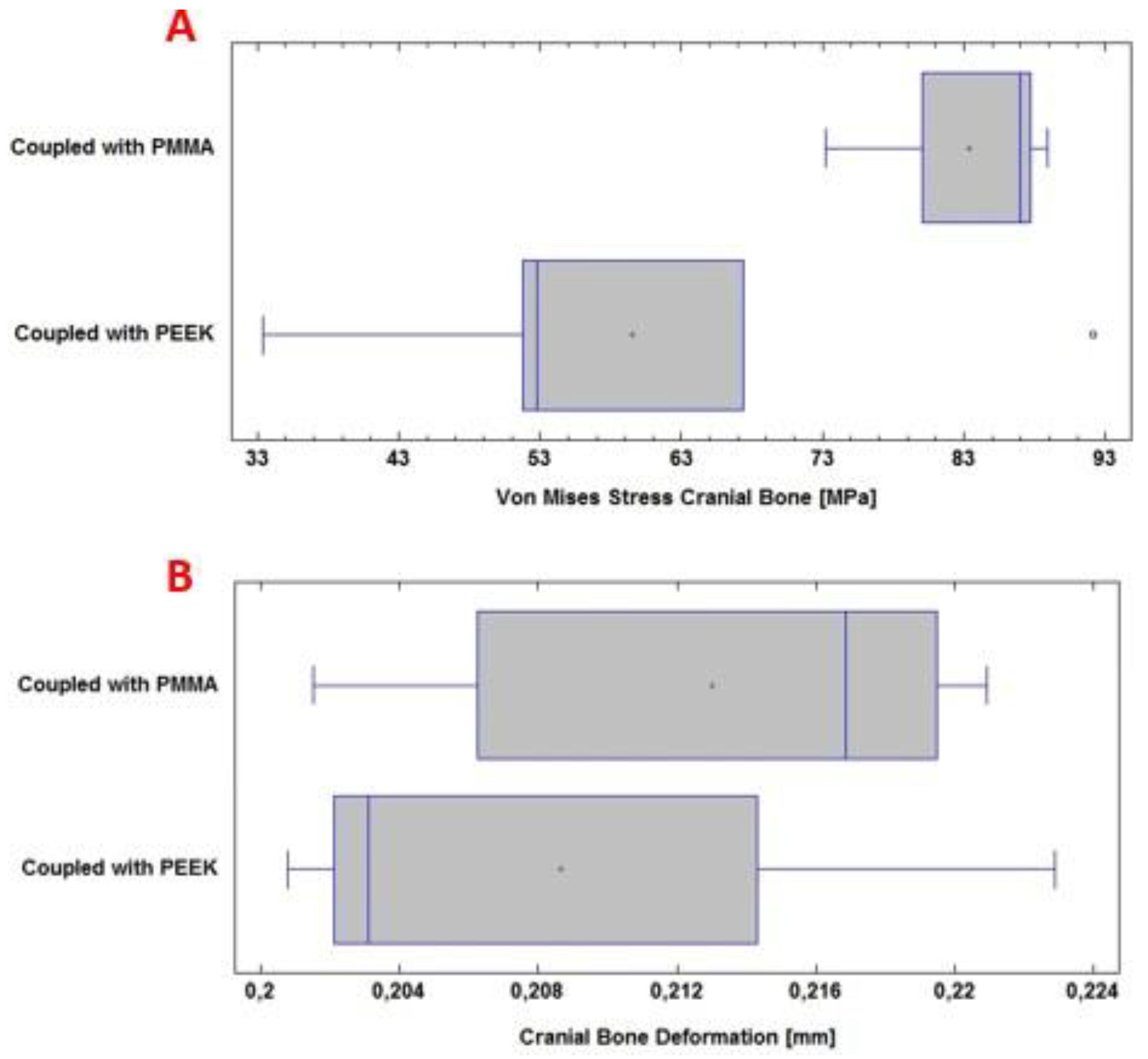
In
Figure 13 (A), the von Mises stress levels in the cranial bone are observed, resulting from the couplings of the PMMA and PEEK implants, respectively. Whereas, in
Figure 13 (B), the total deformation of the cranial bone caused by the coupling of the implant is presented. All of the above under the application of a load “Force” 8000
N.
During the computational analysis, the effect of using PMMA and PEEK implants, respectively, coupled to the cranial bone, was examined to achieve the necessary protection of the internal structures and tissues, before a static load of 8000 N on the external surface of the implant. The mean and standard deviation of the von Mises stress analysis for the cranial bone was 83 ± 7 MPa with PMMA. While with PEEK 59 ± 22 MPa was obtained. In this case, significant differences were observed (p < 0.05), with a confidence level of 95 %.
The total deformation of the cranial bone when coupled with the PMMA implant was also examined. The values for the mean and standard deviation of the analysis were 0.213 ± 0.008 mm. For PEEK, in the same situation, 0.208 ± 0.009 mm was obtained. No significant differences are observed (p > 0.05), with a confidence level of 95 %.
The analysis has focused only on the case of the greater load, because the safety of the personalized implant will depend on this action. The load of 2000
N simulates the inci-dence during the rest-activity; in such a situation, failures will not occur, since the stresses generated in the implant do not exceed the yield stress of either of the two materials ([
28,
34]).
3.2. Post-Operative
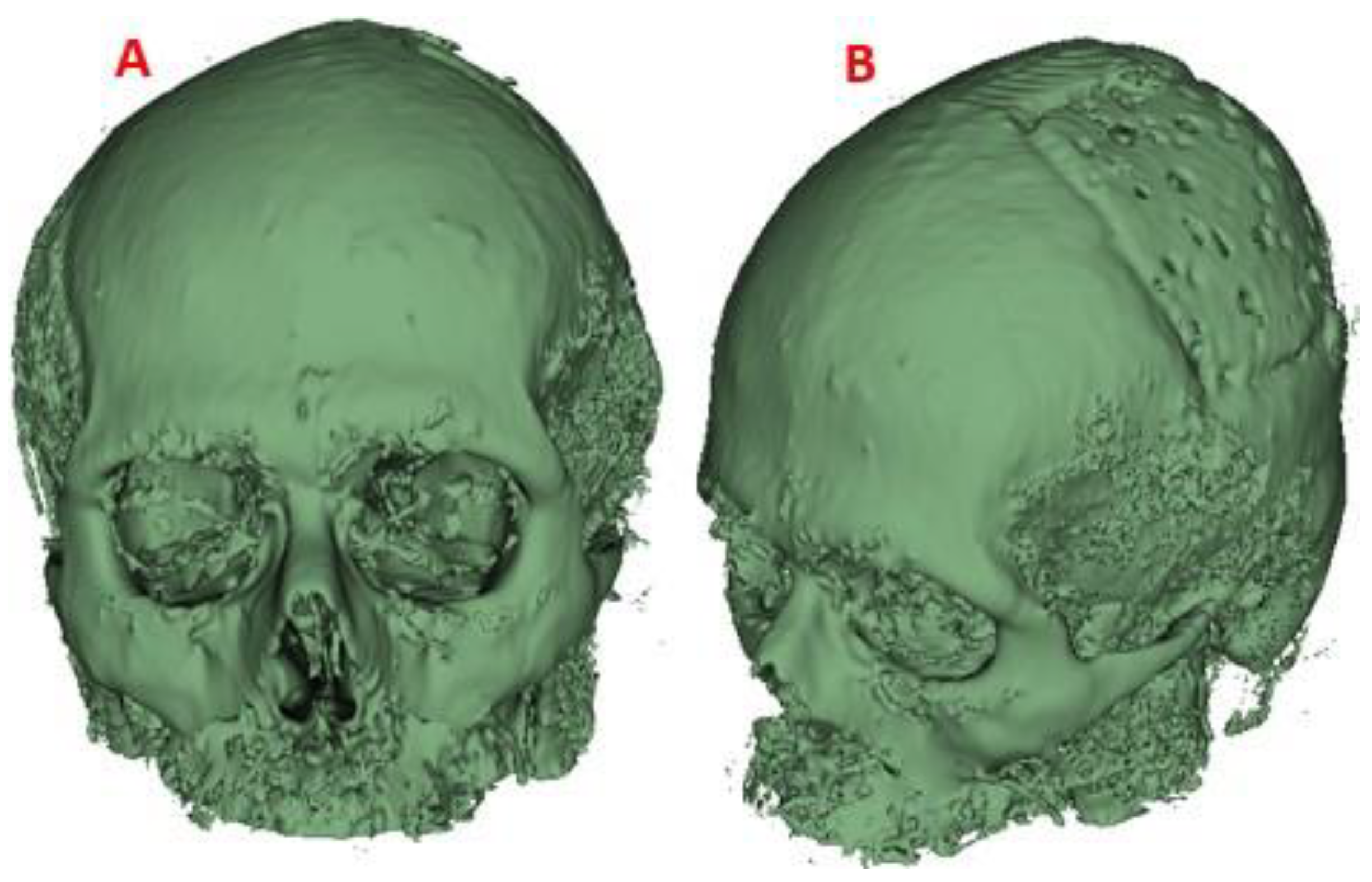
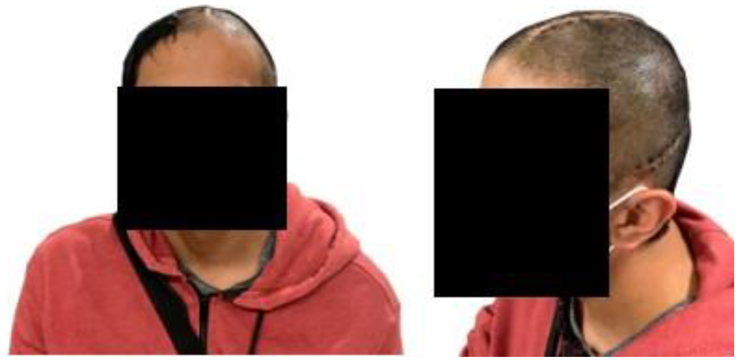
The implant manufactured in PMMA was successfully placed in the patient. The postoperative evolution was satisfactory, there were no complications of any kind, and the person left the hospital facility 48 hours after the intervention. In addition, for follow-up, a visit was scheduled 14 days after surgery. In
Figure 14 the symmetry achieved with the cranial reconstruction is visible. There were also no difficulties with healing, the aesthetic and functional result was as expected and complete patient’s satisfaction.
3.2.1. Postoperative Follow-Up
Computer-Aided Design and Additive Manufacturing have proven to be effective tools in the design of custom implants. The results presented describe the entire custom manufacturing process, surgical planning, finite element analysis and 3D manufacturing, which facilitated the performance of cranioplasty in a patient affected by skull bone cancer. The general procedure (fabrication of the implant and surgical planning) was carried out ac- cording to the proposed methodology and using open-source and commercial software for the segmentation, post-processing and mechanical design stages. The use of free software, whenever possible, was an advantageous factor considering the economic possibilities of the region where the methodology has been applied. In
Figure 15 the final results of the entire process can be seen.
4. Discussion and Conclusions
Through the presentation of a real case, the usefulness of the proposed method for the analysis of clinical cases in the area of neurosurgery and reconstruction of cranial defects with a complex surgical approach has been demonstrated. Through a finite element study, the level of von Mises stresses and total deformations that take place in the coupling of the bone-implant system under static loads were determined, which is established as one more criterion for the design of medical devices for the cranioplasty treatment with biocompatible materials such as PMMA and PEEK.
Four computational analysis were developed under a static external load of 2000 N, which was applied to the upper left part of the implant, simulating an external action that this area of the head would receive during rest-activity; and a load of 8000 N, applied in the centre of the implant, simulating a static impact action. All of the above to determine the stress levels and total deformations of the implant-cranial bone system.
In this investigation it was found that there are no significant differences between the PMMA personalized medical device and the PEEK one, concerning to the total deforma-tions caused by the load of 8000 N, considering the state of load as maximum. Significant differences were found in the von Mises stress distribution.
The decision to know which device to use for cranioplasty treatment will depend on the magnitude of the damage and the patient’s financial availability. In Eastern European and Asian countries, PMMA is currently used as an alternative material for cranioplasty. In [
35] is reported on the use of locally developed polylactic acid and polymethyl methacrylate molds to perform cranioplasties for bone defects in technically demanding areas of the skull, while ensuring good aesthetic results and functional recovery. According to the authors, no surgical complications occurred in 14 patients. In addition, the subjective and objective evaluation revealed a significant improvement in the results. There were also no postoperative complications during a 6-month follow-up period, except in one patient who presented a late infection. Studies like this validate the use of acrylic materials as an alternative for cranioplasty treatment.
Late infection rates from the use of PMMA in custom-made bone implants are fre-quently increased by improper handling of sterilization protocols for manufactured devices, or by bacterial contamination during handling.
In the study presented in [
36], intolerance reactions to resin prostheses are evaluated. The placement of a prosthesis, with the load acting on the supporting tissue; the lining of the oral mucosa; and direct contact with the material often causes a non-physiological situation. As a rule, oral tissues tolerate this situation. However, in some cases, reactions of intolerance to the prosthesis appear. In its triggering, and the appearance of possi-ble mucosal disorders, various factors intervene or interact. Due to the etiological and pathogenic complexity of these complications, the literature does not reflect a uniform opinion regarding the definition, classification and appearance of these clinical pictures.
It has also happened that, in patients who have undergone successive surgery to remove and replace implants, the capillary tissue has lost healing properties, causing the decubitus effect and with it the proliferation of bacteria that contaminate the implanted device. Even so, the cranioplasty surgeries that have been performed in this area of Ecuador have had an approximate average cost of USD 450. In addition, the preoperative prepara-tion with the anatomical test models has helped to reduce the duration of the interventions and the time the patient remains under the effects of anaesthesia, also reducing the risks of surgical complications. A similar scenario is described in [
35,
37]. As reported, the investment in a PMMA implant was USD 50.
The manufacturing process with PEEK has an approximate cost of USD 5000, inacces-sible to the economy of many people. In the present study, however, the simulation results showed that both materials are equal in terms of security and structural integrity that they provide in the event of static load events: they do not exceed the yield point, so under the same demands, they are capable of responding without failure. Regarding the total deformations suffered, no significant differences were observed. In addition, the possible scope of the finite element method has been verified in terms of optimizing the structural properties of the implant to maximize resistance and durability and minimize weight and volume.
In some public and private hospitals in the Republic of Ecuador, a country located in the northwestern region of South America, the introduction of advanced medical technolo-gies, such as 3D printing, has been fundamentally limited for economic reasons and a lack of investment in research and development. However, in a certain way, these limitations have been overcome by applying viable alternatives. For example, keeping PMMA as a fea-sible option in terms of biocompatibility and mechanical performance, and advantageous in economic terms.
In three health institutions in the region, since July 2020, 5 surgeries have been per-formed that required customized bone replacement (the last one made in September 2022). Three cranioplasties, one clavicular implant and one for the sternum-clavicle. All medical devices placed in these patients were manufactured with PMMA. Follow-up has been maintained on each of them up to the present, and in none of the cases has there been any complication. These surgical procedures have been performed under the protection of the rules of the National Agency for Health Regulation, Control and Surveillance (ARCSA-acronym in Spanish), RESOLUTION No. ARCSADE0262016YMIH, Article 20, items a), b), c) and d).
Author Contributions
“Conceptualization, Moncayo-Matute F.P. and Vázquez-Silva E.; methodology, Moncayo-Matute F.P.; Torres-Jara P. B. and Vázquez-Silva E.; software, Moncayo-Matute F.P.; validation, Moncayo-Matute F.P., Torres-Jara P. B. and Peña-Tapia, P. G.; formal analysis, Peña-Tapia, P. G.; investigation, Moncayo-Matute F.P., Peña-Tapia, P. G.; Torres-Jara P. B. and Vázquez-Silva E.; resources, Moya-Loaiza D. P.; data curation, Moya-Loaiza D. P.; writing—original draft preparation, Vázquez-Silva E.; writing—review and editing, Voloria-Ávila T. J.; visualization, Vázquez-Silva E.; supervision, Moya-Loaiza D. P. and Voloria-Ávila T. J.; project administration, Vázquez-Silva E.; funding acquisition, Moya-Loaiza D. P. All authors have read and agreed to the published version of the manuscript.”
Funding
This research received no external funding. However, the work was carried out under the auspices of research projects, Development of customized bone implants with reduction of the affected area through the use of surgical guides and additive manufacturing. Phase I: development of the comprehensive methodology. and Development of customized bone implants with reduction of the affected area through the use of surgical guides and additive manufacturing. Phase II: additive manufacturing with PEEK and PEKK, and evaluation of a superficial modification of the implant, financed by the Salesian Polytechnic University. Approving resolutions: RESOLUTION No002-003-2020-07-15 and RESOLUTION No005-005-2023-05-25, respectively.
Informed Consent Statement
“Informed consent was obtained from all subjects involved in the study.” “Written informed consent has been obtained from the patient(s) to publish this paper”
Data Availability Statement
Data included in article/supplementary material/referenced in the article
Acknowledgments
The authors of this work appreciate the support provided by the Research Group on New Materials and Transformation Processes (GIMAT) of the Mechanical Engineering Carrier, in terms of the availability of hours to carry out the research processes. The authors also appreciate the support provided by the Neurosurgery Department of “Instituto de lucha contra el Cáncer – SOLCA”, in Cuenca city, which provided its facilities for performing the surgery and patient follow-up. The authors also thank Group 1 of the Biomedicine Career at UPS, who during teaching activities corresponding to the Biomaterials subject, in the period 62 (March-August 2023) collaborated with the printing of the test anatomical model shown in Fig. 8, in the present work.
Conflicts of Interest
“The authors declare no conflict of interest.”
References
- Chepurnyi, Y.; Chernogorskyi, D.; Kopchak, A.; Petrenko, O. Clinical efficacy of peek patient-specific implants in orbital reconstruction. Journal of oral biology and craniofacial research 2020, 10, 49–53. [CrossRef]
- Limaye, N.; Veschini, L.; Coward, T. Assessing biocompatibility & mechanical testing of 3D-printed PEEK versus milled PEEK. Heliyon 2022, 8, e12314. [CrossRef]
- Zheng, Z.; Liu, P.; Zhang, X.; Zou, X.; Mei, X.; Zhang, S.; Zhang, S.; et al. Strategies to improve bioactive and antibacterial properties of polyetheretherketone (PEEK) for use as orthopedic implants. Materials Today Bio 2022, p. 100402. [CrossRef]
- Shi, Y.; Deng, T.; Peng, Y.; Qin, Z.; Ramalingam, M.; Pan, Y.; Chen, C.; Zhao, F.; Cheng, L.; Liu, J. Effect of Surface Modification of PEEK Artificial Phalanx by 3D Printing on its Biological Activity. Coatings 2023, 13, 400. [CrossRef]
- Kang, J.; Wang, L.; Yang, C.; Wang, L.; Yi, C.; He, J.; Li, D. Custom design and biomechanical analysis of 3D-printed PEEK rib prostheses. Biomechanics and modeling in mechanobiology 2018, 17, 1083–1092. [CrossRef]
- Zhao, Y.; Zhao, K.; Li, Y.; Chen, F. Mechanical characterization of biocompatible PEEK by FDM. Journal of Manufacturing Processes 2020, 56, 28–42. [CrossRef]
- Oladapo, B.I.; Zahedi, S.A.; Ismail, S.O. Mechanical performances of hip implant design and fabrication with PEEK composite. Polymer 2021, 227, 123865. [CrossRef]
- Thieringer, F.M.; Sharma, N.; Mootien, A.; Schumacher, R.; Honigmann, P. Patient specific implants from a 3D printer–an innovative manufacturing process for custom PEEK implants in cranio-maxillofacial surgery; Springer, 2018.
- Honigmann, P.; Sharma, N.; Schumacher, R.; Rueegg, J.; Haefeli, M.; Thieringer, F. In-hospital 3D printed scaphoid prosthesis using medical-grade polyetheretherketone (PEEK) biomaterial. BioMed Research International 2021, 2021. [CrossRef]
- Rodzen´, K.; Sharma, P.K.; McIlhagger, A.; Mokhtari, M.; Dave, F.; Tormey, D.; Sherlock, R.; Meenan, B.J.; Boyd, A. The direct 3D printing of functional PEEK/hydroxyapatite composites via a fused filament fabrication approach. Polymers 2021, 13, 545.
- Zhang, J.; Su, Y.; Rao, X.; Pang, H.; Zhu, H.; Liu, L.; Chen, L.; Li, D.; He, J.; Peng, J.; et al. Additively manufactured polyether ether ketone (PEEK) skull implant as an alternative to titanium mesh in cranioplasty. International Journal of Bioprinting 2023, 9. [CrossRef]
- Rosa-Sainz, A.; García-Romeu, M.; Ferrer, I.; Silva, M.; Centeno, G. On the effective peek application for customized cranio-maxillofacial prostheses: An experimental formability analysis. Journal of Manufacturing Processes 2023, 86, 66–84. [CrossRef]
- Bianchi, F.; Signorelli, F.; Di Bonaventura, R.; Trevisi, G.; Pompucci, A. One-stage frame-guided resection and reconstruction with PEEK custom-made prostheses for predominantly intraosseous meningiomas: technical notes and a case series. Neurosurgical review 2019, 42, 769–775. [CrossRef]
- Narciso, R.; Basile, E.; Bottini, D.J.; Cervelli, V. PEEK implants: an innovative solution for facial aesthetic surgery. Case Reports in Surgery 2021, 2021. [CrossRef]
- Haleem, A.; Javaid, M.; Vaish, A.; Vaishya, R. Three-dimensional-printed polyether ether ketone implants for orthopedics. Indian journal of orthopaedics 2019, 53, 377. 464. [CrossRef]
- Zhang, J.; Tian, W.; Chen, J.; Yu, J.; Zhang, J.; Chen, J. The application of polyetheretherketone (PEEK) implants in cranioplasty. Brain research bulletin 2019, 153, 143–149.
- Shah, A.M.; Jung, H.; Skirboll, S. Materials used in cranioplasty: a history and analysis. Neurosurgical focus 2014, 36, E19. [CrossRef]
- Wind, J.J.; Ohaegbulam, C.; Iwamoto, F.M.; Black, P.M.; Park, J.K. Immediate titanium mesh cranioplasty for treatment of postcraniotomy infections. World neurosurgery 2013, 79, 207–e11. [CrossRef]
- Goiato, M.C.; Anchieta, R.B.; Pita, M.S.; dos Santos, D.M. Reconstruction of skull defects: currently available materials. Journal of Craniofacial Surgery 2009, 20, 1512–1518.
- Kim, B.J.; Hong, K.S.; Park, K.J.; Park, D.H.; Chung, Y.G.; Kang, S.H. Customized cranioplasty implants using three-dimensional printers and polymethyl-methacrylate casting. Journal of Korean Neurosurgical Society 2012, 52, 541–546. [CrossRef]
- Turgut, G.; Özkaya, Ö.; Kayal, M.U. Computer-aided design and manufacture and rapid prototyped polymethylmethacrylate reconstruction. Journal of Craniofacial Surgery 2012, 23, 770–773. 475. [CrossRef]
- Nguyen, P.D.; Khechoyan, D.Y.; Phillips, J.H.; Forrest, C.R. Custom CAD/CAM implants for complex craniofacial reconstruction in children: Our experience based on 136 cases. Journal of Plastic, Reconstructive & Aesthetic Surgery 2018, 71, 1609–1617. [CrossRef]
- Liang, E.S.; Tipper, G.; Hunt, L.; Gan, P.Y.C. Cranioplasty outcomes and associated complications: a single-centre observational study. British journal of neurosurgery 2016, 30, 122–127. 479. [CrossRef]
- Iaccarino, C.; Viaroli, E.; Fricia, M.; Serchi, E.; Poli, T.; Servadei, F. Preliminary results of a prospective study on methods of cranial reconstruction. Journal of Oral and Maxillofacial Surgery 2015, 73, 2375–2378. [CrossRef]
- Paredes, I.; Castaño-León, A.M.; Munarriz, P.M.; Martínez-Perez, R.; Cepeda, S.; Sanz, R.; Alén, J.F.; Lagares, A. Cranioplasty after decompressive craniectomy. A prospective series analyzing complications and clinical improvement. Neurocirugia 2015, 26, 115–125. 484. [CrossRef]
- Inchingolo, A.D.; Pezzolla, C.; Patano, A.; Ceci, S.; Ciocia, A.M.; Marinelli, G.; Malcangi, G.; Montenegro, V.; Cardarelli, F.; Piras, F.; et al. Experimental Analysis of the Use of Cranial Electromyography in Athletes and Clinical Implications. International Journal of Environmental Research and Public Health 2022, 19, 7975. [CrossRef]
- Ridwan-Pramana, A.; Marcián, P.; Borák, L.; Narra, N.; Forouzanfar, T.; Wolff, J. Structural and mechanical implications of PMMA implant shape and interface geometry in cranioplasty–A finite element study. Journal of Cranio-Maxillofacial Surgery 2016, 44, 34–44. [CrossRef]
- Yoganandan, N.; Pintar, F.A.; Zhang, J.; Baisden, J.L. Physical properties of the human head: mass, center of gravity and moment of inertia. Journal of biomechanics 2009, 42, 1177–1192. [CrossRef]
- Qi, W.; Yan, Y.b.; Zhang, Y.; Lei, W.; Wang, P.j.; Hou, J. Study of stress distribution in pedicle screws along a continuum of diameters: a three-dimensional finite element analysis. Orthopaedic surgery 2011, 3, 57–63. [CrossRef]
- Ameen, W.; Al-Ahmari, A.; Mohammed, M.; Abdulhameed, O.; Umer, U.; Moiduddin, K. Design, finite element analysis (FEA), and fabrication of custom titanium alloy cranial implant using electron beam melting additive manufacturing. Advances in Production Engineering & Management 2018, 13, 267–278. [CrossRef]
- S¸ims¸ek, H.; Zorlu, E.; Kaya, S.; Baydog˘ an, M.; Atabey, C.; Çolak, A. A new multipartite plate system for anterior cervical spine surgery; finite element analysis. British Journal of Neurosurgery 2018, 32, 276–282.
- Motherway, J.A.; Verschueren, P.; Van der Perre, G.; Vander Sloten, J.; Gilchrist, M.D. The mechanical properties of cranial bone: the effect of loading rate and cranial sampling position. Journal of biomechanics 2009, 42, 2129–2135. doi:10.1016/j.jbiomech.2009.05.030.
- Gómez, F.; Elices, M. Fracture of components with V-shaped notches. Engineering fracture mechanics 2003, 70, 1913–1927. [CrossRef]
- Moncayo-Matute, F.P.; Peña-Tapia, P.G.; Vázquez-Silva, E.; Torres-Jara, P.B.; Moya-Loaiza, D.P.; Abad-Farfán, G.; Andrade-Galarza, A.F. Surgical planning and finite element analysis for the neurocraneal protection in cranioplasty with PMMA: A case study. Heliyon 2022, 8. [CrossRef]
- Kaya, I˙.; Yakar, H.; Kesen, E. Low-cost 3-d-printer–assisted personalized cranioplasty treatment: A case series of 14 consecutive patients. World Neurosurgery 2023.
- Moncayo-Matute, F.P.; Torres-Jara, P.B.; Vázquez-Silva, E.; Peña-Tapia, P.G.; Moya-Loaiza, D.P.; Abad-Farfán, G. Finite element analysis of a customized implant in PMMA coupled with the cranial bone. Available at SSRN 4484792. 509. [CrossRef]
- Rubio-Pérez, I.; Diaz Lantada, A. Surgical planning of sacral nerve stimulation procedure in presence of sacral anomalies by using personalized polymeric prototypes obtained with additive manufacturing techniques. Polymers 2020, 12, 581. [CrossRef]
Figure 1.
CT Scan Images: segmented model (A), axial view (B), coronal view (C) and sagittal view (D).
Figure 1.
CT Scan Images: segmented model (A), axial view (B), coronal view (C) and sagittal view (D).
Figure 2.
Computational model of the skull: (A) Lateral view, showing damage or trauma to the local parietal bone. (B) Front view of the cranial model, the defect is observed, and the lack of symmetry. (C) Posterior view of the cranial model.
Figure 2.
Computational model of the skull: (A) Lateral view, showing damage or trauma to the local parietal bone. (B) Front view of the cranial model, the defect is observed, and the lack of symmetry. (C) Posterior view of the cranial model.
Figure 3.
Reconstruction of the cranial 3D model with the help of the customized implant to simulate the clinical scenario: (A) Geometric model of the implant to cover the defect in the patient’s parietal area. (B) Geometric model of the customized implant, coronal contour perimeter zone. (C) 3D view of the implant, showing the internal shape and the variation of the angulation of the contact interface along the contour.
Figure 4.
Reconstruction of the skull: (A) Lateral view of the skull and customized implant, showing the reconstruction. (B) Frontal View, defect covered by the cranial implant.
Figure 4.
Reconstruction of the skull: (A) Lateral view of the skull and customized implant, showing the reconstruction. (B) Frontal View, defect covered by the cranial implant.
Figure 5.
Configuration of the model to simulate the clinical scenario, highlighting the contour of the defect and adjustment of the implant: (A) Geometric model of the location of the defect in the left lateral parietal area of the patient. (B) Geometric model of the customized implant, showing the contours of the perimeter adaptation to the cranial bone.
Figure 6.
Loading conditions: (A) 8000 N force acting on the central area of the implant. (B) 2000 N force, acting on the upper left parietal part of the implant. (C) Fixed Support, embedment at the base of the skull.
Figure 6.
Loading conditions: (A) 8000 N force acting on the central area of the implant. (B) 2000 N force, acting on the upper left parietal part of the implant. (C) Fixed Support, embedment at the base of the skull.
Figure 7.
Mesh elements: (A) Mesh of the implant with fixation towards the skull. (B) The meshing of the cranial model with the implant.
Figure 7.
Mesh elements: (A) Mesh of the implant with fixation towards the skull. (B) The meshing of the cranial model with the implant.
Figure 8.
Cranial model for surgical planning: (A) Frontal view. (B) Lateral view, area of damage. (C) Back view.
Figure 8.
Cranial model for surgical planning: (A) Frontal view. (B) Lateral view, area of damage. (C) Back view.
Figure 9.
Cranial model with the patient-specific implant: (A) Cranial bio-model with the PMMA implant coupled. (B) Cranial bio-model with the PEEK implant coupled.
Figure 9.
Cranial model with the patient-specific implant: (A) Cranial bio-model with the PMMA implant coupled. (B) Cranial bio-model with the PEEK implant coupled.
Figure 10.
von Mises stress distribution in the implant and cranial bone: (A) Load condition “Force” 2000 N, implant with PMMA. (B) Load condition “Force” 2000 N, implant with PEEK. (C) Load condition “Force” 8000 N, implant with PMMA. (D) Load condition “Force” 8000 N, implant with PEEK.
Figure 10.
von Mises stress distribution in the implant and cranial bone: (A) Load condition “Force” 2000 N, implant with PMMA. (B) Load condition “Force” 2000 N, implant with PEEK. (C) Load condition “Force” 8000 N, implant with PMMA. (D) Load condition “Force” 8000 N, implant with PEEK.
Figure 11.
Deformation in the implant and cranial bone: (A) Load condition “Force” 2000 N, implant with PMMA. (B) Load condition “Force” 2000 N, implant with PEEK. (C) Load condition “Force” 8000 N, implant with PMMA. (D) Load condition “Force” 8000 N, implant with PEEK..
Figure 11.
Deformation in the implant and cranial bone: (A) Load condition “Force” 2000 N, implant with PMMA. (B) Load condition “Force” 2000 N, implant with PEEK. (C) Load condition “Force” 8000 N, implant with PMMA. (D) Load condition “Force” 8000 N, implant with PEEK..
Figure 12.
Statistical analysis: (A) von Mises stresses of the PMMA and PEEK implants, respectively. (B) Deformation of the PMMA and PEEK implants, respectively.
Figure 12.
Statistical analysis: (A) von Mises stresses of the PMMA and PEEK implants, respectively. (B) Deformation of the PMMA and PEEK implants, respectively.
Figure 13.
Statistical analysis: (A) von Mises stresses in the cranial bone. (B) Deformation of the cranial bone.
Figure 13.
Statistical analysis: (A) von Mises stresses in the cranial bone. (B) Deformation of the cranial bone.
Figure 14.
CT scan of the patient, with the custom PMMA implant, 14 days post-surgery: (A) Image of the skull with the PMMA implant attached, front view. (B) Image of the skull with the attached PMMA implant, 3D view.
Figure 14.
CT scan of the patient, with the custom PMMA implant, 14 days post-surgery: (A) Image of the skull with the PMMA implant attached, front view. (B) Image of the skull with the attached PMMA implant, 3D view.
Figure 15.
Patient benefited from the personalized PMMA implant.
Figure 15.
Patient benefited from the personalized PMMA implant.
Table 1.
Material properties of components used in the simulation of the assembly model 3D.
Table 1.
Material properties of components used in the simulation of the assembly model 3D.
| Parameter |
Cranial cortical bone |
PMMA |
PEEK |
| Young’s modulus |
Eb = 15000 MPa
|
EPMMA = 3000 MPa
|
EPEEK = 3600 MPa
|
| Poisson’s ratio |
µb = 0.3 |
µPMMA = 0.38 |
µPEEK = 0.39 |
| Ultimate tensile |
σu,b = 130 MPa
|
—– |
σu,PEEK = 172 MPa
|
| Yield strength |
—– |
σy,PMMA = 72 MPa
|
σy,PEEK = 90 MPa
|
| Reference |
[32] |
[33] |
[33] |
Table 2.
FDM additive manufacturing characteristics and parameters.
Table 2.
FDM additive manufacturing characteristics and parameters.
| Characteristics and manufacturing parameters |
Fused Deposition Modeling |
| Company and model |
Creality CR-X Pro (2019 Updated) |
| Maximum build envelope |
300 × 300× 400 mm3 |
| Nozzle diameter |
0.4 mm
|
| Positioning resolution (X/Y/Z) |
1.25 µm/1.25 µm/1 µm |
| Selected layer thickness |
0.10 mm
|
| Printed filament line width |
0.4 mm
|
Table 3.
Von Mises stresses and total deformation of the structures1.
Table 3.
Von Mises stresses and total deformation of the structures1.
| Structure |
Material |
von Mises Stress [MPa] |
Total Deformation [mm] |
Load State [N] |
| Skull |
Cortical bone |
40 ± 10 |
0.080 ± 0.001 |
2000 |
| Implant |
PMMA |
40 ± 7 |
0.56 ± 0.02 |
2000 |
| Skull |
Cortical bone |
36 ± 8 |
0.073 ± 0.001 |
2000 |
| Implant |
PEEK |
44 ± 5 |
0.42 ± 0.08 |
2000 |
| Skull |
Cortical bone |
83 ± 7 |
0.210 ± 0.008 |
8000 |
| Implant |
PMMA |
103 ± 20 |
2.71 ± 0.21 |
8000 |
| Skull |
Cortical bone |
59 ± 22 |
0.21 ± 0.01 |
8000 |
| Implant |
PEEK |
99 ± 11 |
2.30 ± 0.03 |
8000 |
|
Disclaimer/Publisher’s Note: The statements, opinions and data contained in all publications are solely those of the individual author(s) and contributor(s) and not of MDPI and/or the editor(s). MDPI and/or the editor(s) disclaim responsibility for any injury to people or property resulting from any ideas, methods, instructions or products referred to in the content. |
© 2023 by the authors. Licensee MDPI, Basel, Switzerland. This article is an open access article distributed under the terms and conditions of the Creative Commons Attribution (CC BY) license (http://creativecommons.org/licenses/by/4.0/).
