Submitted:
19 July 2023
Posted:
19 July 2023
You are already at the latest version
Abstract
Reductive leaching in the Bayer cycle using of iron (2+) allows Al extraction to be significantly increased by magnetization of Al-goethite and Al-hematite. However, the use of expensive iron (2+) salts or iron powder as a source of iron (2+) leads to a significant increase in production costs. In this work, the feasibility of a new method, the reductive leaching of bauxite using an electrolysis process, was investigated. Reduction of iron minerals of boehmitic bauxite in both Bayer solution and purely alkaline solutions were carried out. Experiments were performed using a plate cathode and a bauxite suspension in alkaline solution, as well as using a bulk cathode with a stainless-steel mesh at the bottom of the cell as the current supply. During the electrolysis process, the potential of the cathode relative to the reference electrode was measured as a function of current at different concentrations of solid (100-300 g L–1) and suspension temperatures (95-120 °C). It is shown that the current efficiency using suspension and plate cathode with the predominant deposition of Fe doesn’t exceed 50% even with the addition of magnetite to increase the contact of solid phase with the current supply. With the use of a bulk cathode, the reduction of iron minerals leads predominantly to the formation of magnetite with the efficiency of using electric current more than 80%. As a result of preliminary desilication and electroreduction it is possible to extract more than 97% of Al from bauxite, and to increase the iron content in the bauxite residue to 57-58%.
Keywords:
hematite electroreduction
; boehmitic bauxite
; Al extraction
; reductive leaching
; red mud
; bauxite residue
; magnetite
; waste utilization
1. Introduction
The Bayer process is used worldwide for the alumina production. This process involves the alkaline leaching of bauxite to extract Al, followed by the precipitation of Al(OH)3 to recycle the solution [1,2,3]. The leaching process results in the formation of a solid residue, commonly referred to as a bauxite residue, which consists of iron minerals, hydrous aluminosilicates, which are formed by the interaction of aluminium and silicon compounds in solution, and other impurity minerals [4,5,6]. Some of the aluminium in bauxite is present in the form of refractory at standard leaching alumogoethite (Al-goethite) and alumohematite (Al-hematite) [7,8,9]. The study of Li et al. [10,11] showed that reductive leaching can increase the Al extraction by magnetization of Al-goethite and Al-hematite. The addition of iron (2+) can also decrease aluminium losses by preventing the formation of desilication products and sodium titanate [12]. Previously, iron (2+) sulphate (FeSO4) [13], organic compounds [14] and iron powder [15] was suggested for magnetization of iron minerals. However, the use of additional reagents increases the cost of the alumina production process, so in this work, the possibility of using electrolysis for iron mineral reduction has investigated.
Hematite (Fe2O3) is the most studied raw material for electroreduction to metallic iron. Studies have been carried out both in suspensions [16,17,18] and in bulk ceramic cathodes [19,20,21]. Despite the low electrical conductivity, electrodeposition, and electro-reduction of Fe2O3 it was found that this process is feasible. Current yields in excess of 90% have been obtained using NaOH solutions with concentrations in excess of 50% [22]. Various raw materials are being considered for electrochemical reduction to produce metallic iron, including iron-rich wastes such as BR from the aluminium industry [23,24].
Maihatchi et al. [23] investigated the possibility of electrochemical reduction of hematite ore and iron minerals in BR (Alteo, France). It was shown that the use of BR and highly concentrated solutions of caustic alkali (500 g L–1 NaOH) at 110 °C leads to a significant decrease in current yield compared to hematite ore. The greatest difference was observed at high current density (above 100 A m–2, where the current yield for hematite was more than 80%, and for BR did not exceed 30%. According to the authors, the decrease in electrolysis efficiency when using BR was due to the large amount of impurities in the BR, which prevented the adsorption of hematite on the cathode surface. This was confirmed by the addition of commercial hematite and aluminosilicates at different ratios.
Koutsoupa et al. [24] researched the possibility of hematite reduction from BR in a highly concentrated alkaline solution (50% NaOH or 762,7 g L–1 NaOH). The results showed that the Faradaic current efficiency was strongly dependent on the process temperature. The highest current efficiency (> 70%) was obtained at a temperature of 125 °C, and a decrease in temperature or an increase in temperature led to a significant decrease in current efficiency to 30-40%. This phenomenon is due to the insufficient rate of iron dissolution at low temperatures and the presence of a significant number of gas bubbles in the solution near the boiling point, which prevents contact with the cathode.
The mechanism of the electrochemical reduction of hematite can be described by the following chemical reactions. A strong solution of caustic alkali can dissolve hematite and turn it to sodium ferrite. In water, some of the ferrite goes into the solution as hydroxocomplexes (Equation (1)) or precipitate in the form of iron hydroxide (Equation (2)).
Fe2O3 + NaOH = NaFeO2 + H2O,
FeO2– + 2H2O = Fe(OH)4–.
The hydroxocomplexes are electrochemically reduced to Fe(OH)3– (Equation (3)) or to iron (Equation (4)). Fe(OH)3– can also interact with hematite to form magnetite (Equation (5)).
Fe(OH)4– + e- = Fe(OH)3– + OH–,
Fe(OH)3– + 2e- = Fe + 3OH–,
Fe2O3 + Fe(OH)3- = Fe3O4 + 4H2O.
Hematite can be reduced by solid-phase reaction to elemental iron (Equation (6)) and magnetite (Equation (7)). Under alkaline conditions, oxygen is converted to the hydroxyl ion according to Equation (8):
Fe2O3 + 3e- = 2Fe + 3O2–,
Fe2O3 + 2e- = 2Fe3O4 + O2–,
O2- + H2O = 2OH–.
The magnetite formed by the reduction of hematite can also be reduced to iron (Equation (9)) and dissolved to form hydroxocomplexes (Equation (10)):
Fe3O4 + 4e- = 3Fe + 4O2–,
Fe3O4 + 4H2O + OH- + 2e- = 3Fe(OH)3–.
According to the described system of equations, the process can proceed both in solid-phase (Equation (6)) or by dissolution of hematite in an alkaline solution with subsequent reduction to metallic iron (Equations (2)-(4)). The solubility of hematite in alkaline solution is low, so when iron is released from solution during electrolysis, this allows new amounts of hematite can dissolve (Equation (2)). Also, according to Equations (5) and (7) reduction of hematite to magnetite is possible. It was shown in [18,25,26] that the current efficiency of magnetite electroreduction is the lowest in the hematite - goethite - magnetite sequence. Accordingly, magnetite formed by Equation (5) leads to a decrease in the process efficiency. Under certain overvoltage conditions, a side reaction can also be presented by the release of hydrogen. Hydrogen in turn can also reduce hematite. When the process is carried out at atmospheric pressure, the contribution of this reaction will be very low, as it is not possible to create the necessary concentration of hydrogen in the solution.
This study investigates the electrochemical reduction of iron minerals from bauxite suspended in an aluminate solution, that can be produced simultaneously with the Bayer leaching process. This would eliminate the need for additives in the Bayer reduction process. For this purpose, experiments were carried out on the reduction of iron minerals of high-iron boehmitic bauxite suspended in alkaline solution. Experiments were carried out using a bauxite-based suspension and a plate cathode as well as a bulk cathode. For the bulk cathode experiments, the slurry was thickened prior to electrolysis and current flow was conducted through a stainless steel mesh at the bottom of the cell. The solid phase obtained by electroreduction was then subjected to standard Bayer leaching to extract Al and complete the reduction of iron minerals. The solid phase obtained by electrolysis of suspensions and after high-pressure leaching was subjected to various physical and chemical analyses to determine the efficiency and the mechanism of the processes.
2. Materials and Methods
2.1. Materials
Bauxite from the Middle Timan deposit (Ukhta, Russia) was used as raw material. The chemical and phase composition are presented in Table 1 and Figure 1. This bauxite type is characterized as a high iron and silicon content. It requires high-pressure leaching in order to obtain an oversaturated aluminate solution. Our previous research [27] using Mössbauer spectroscopy has shown that the bauxite contains high amount of Al-goethite, Al-hematite, and chamosite that are refractory for standard Bayer leaching.
Bauxite was pre-milled to obtain a class -73 μm more than 80%, less than 100 μm - 98%. To obtain a suspension, the crushed bauxite was mixed with synthetic Bayer solution (150 g L-1 Al2O3 and 300 g L-1 Na2O) or NaOH solution with a concentration of 400 g L-1 Na2O.
Solutions were obtained by mixing NaOH and Al(OH)3 (if necessary) of analytical grade with distilled water and then stirring at 108 °C for 30 min. After leaching, the solutions were filtered by a Buechner funnel to separate the undissolved residue. In some experiments, magnetite concentrate was added in addition to the bauxite, the elemental and phase composition of which is shown in Table 2 and Figure 2. This concentrate was obtained by reductive leaching of BR sands from the Friguia refinery (Guinea) in the presence of iron (2+) hydroxide according to the method described in [28].
2.2. Experimental
The schematic view of the experimental setup for the study of bauxite iron minerals reduction using electrolysis is shown in Figure 3.
As shown in Figure 3a, the experimental setup consisted of a 500 mL glass beaker placed in an oil bath (DF-101S, Zhejiang Lichen Instrument Technology Co., Ltd.) equipped with a magnetic stirrer. The suspension was heated to the desired temperature inside the beaker before the electrolysis. The temperature of the suspension was controlled using a temperature sensor, which was connected to the PID-regulator of the oil bath. A stainless steel plate cathode with an immersed area of 9.91 cm2 was used as a current supply in the experiments with constant stirring of the suspension. During electrolysis, the potential of the cathode was measured relative to the reference electrode as a function of current at different concentrations of solid (100-300 g L-1) and suspension temperature (95-120 °C) using a potentiostat ZiveLab SP 2 (Zivelab, Korea).
When using a bulk cathode, round pieces of mesh with diameters of 6 cm, 7 cm, and 9.2 cm were used as the current supply. The area of the mesh, taking into account the dimensions of the mesh cells, the wire thickness, and the length and thickness of the wire connecting the terminal of the potentiostat to the mesh, was 40 cm2, 75 cm2, and 110 cm2, respectively. For the experiments with the bulk cathode, a 100 g bauxite sample was leached for 1 h with constant stirring using an overhead stirrer at a temperature of 120 °C in 1 L of alkaline solution with a concentration of 400 g L-1 Na2O in a stainless steel reactor coated by PTFE with a volume of 2 L in order to preliminarily desilicate the bauxite. According to previous research this step [27] helps increase the efficiency of the subsequent reductive leaching.
The resulting pulp was then subjected to thickening for a duration of 30 min. The underflow, containing 300 mL of sand, was separated from the clarified solution after 30 min of thickening, and the underflow was used for potentiodynamic measurements and the electrolysis process at a constant current strength of 1.945 A and a pulp temperature of 120 °C. After electrolysis the suspension was filtered using the Buchner funnel. The filtered and washed residue was then subjected to complete Al extraction using high-pressure Bayer leaching at 250 °C for 30 min in a steel bomb placed in the thermostat. After filtration and washing, the residues were dried at 110 °C for 8 h and then subjected to the analysis. A 10 cm2 nickel plate was used as an anode. The reference electrode was a mercury–mercury oxide electrode OH-/HgO,Hg (RE-1A, YM, Shaanxi, China). Potential of the electrode relative to the hydrogen electrode at 25 °C in 10N KOH solution = 0.098 V. All potentials in the paper are given relative to the reference electrode. The reference electrode was placed in a separate beaker connected to the main beaker using an electrochemical key (with Luggin capillary inside suspension) on a tripod outside the oil bath. The electrochemical key and the beaker with the reference electrode were filled with 10 N NaOH solution. The electrodes were connected to the corresponding terminals of the potentiostat.
2.3. Analysis
The mineralogy of the raw bauxite and the solid residue after alkaline leaching was measured by X-ray diffraction (XRD) using a Difrei-401 X-ray diffractometer (JSC Scientific Instruments, Saint Petersburg, Russia) with a Cr-Kα radiation source and a 2θ range of 14° to 140° with an exposure of 30 min. The x-ray source operating mode was set to 25 kW/4 mA. Mineral phase analysis was performed with Match! 3 software (Crystal Impact, Bonn, Germany).
An Axios Max X-ray fluorescence (XRF) spectrometer (Panalytical, Almelo, The Netherlands) was used to analyze the solid residue after pulp filtration. The Fe (2+) content in solid residue were determined using chemical analysis (dichromate titrimetric method was used for total iron measurement, trivalent content being deduced after full reduction using stannous chloride). Scanning electron microscopy with energy dispersive X-ray spectroscopy (SEM-EDX, Vega III, Tescan, Brno, Czech Republic) was used to study the surface morphology and elemental composition of the solid residue.
2.4. Calculations
Using the setup in Figure 3a, the current density was calculated based on the active area of the current supply (stainless steel plates). When the mesh was in contact with the solid (Figure 3b), there were particles that acted as a cathode surface themselves, making a bulk cathode. It was therefore difficult to calculate the surface of the cathode, and only the current was estimated as a function of the cathode potential.
The faradaic current efficiency was estimated by measuring the cathode mass before and after the experiment, and the resulting pulp was filtered to separate the solid residue, which was then analyzed for iron (2+) content. The results of the calculations of the change in cathode mass and the amount of magnetite in the solid residue (no elemental iron was detected in this solid residue) were summed up to determine the total current efficiency according to Equations 11 and 13.
Electrode reaction at the cathode to produce magnetite (Equation 11):
The electrochemical equivalent to produce magnetite is equal to (Equation 12):
where – electrochemical equivalent of producing 1 g of magnetite, g C–1; – magnetite molar mass, g mol–1; 96485 – Faraday constant, C mol–1. Electrode reaction at the cathode to produce iron (Equation 13):
The electrochemical equivalent to produce 1 g of iron is equal to (Equation 14):
where – electrochemical equivalent of producing 1 g of iron, g C–1; is the molar mass of magnetite, g mol–1. It takes 12.4 times more electricity to produce a unit mass of iron than to produce a unit mass of magnetite.
When using the bulk cathode (Figure 3b), most reduction products were found in the solid residue. The current efficiency can be determined by knowing the amount of magnetite and iron in the solid residue, which in practice is often a challenging task or can be estimated using semi-quantitative methods via XRD or Mössbauer spectroscopy [20]. Hence, the determination of the coefficient of current efficiency, rather than the faradaic current efficiency, was made by utilizing a bulk cathode.
In order to evaluate the coefficient of current efficiency by utilizing the bulk cathode, the pulp obtained was subjected to Bayer leaching in an aluminate solution at a temperature of 250 °C for a duration of 30 min, with a ratio of L:S (liquid to solid) equal to 3.5 to 1. This process resulted in the conversion of elemental iron into magnetite [29]. Since magnetite is obtained after high-pressure oxidation of iron (Equations (15)-(17)), it is possible to calculate the electrolysis efficiency coefficient, which will take into account the share of current that goes to obtain magnetite both directly as a result of electrolysis and due to chemical reactions of the obtained elemental iron in the high-pressure reactor.
Fe + H2O + OH− = HFeO2− + H2,
Fe2O3 + HFeO2− = Fe3O4 + OH–,
3Fe2O3 + H2 = 2Fe3O4 + H2O.
According to the stoichiometry of Equations (15)-(17), for one mole of Fe, 3 moles of magnetite or 12.4 g of magnetite per 1 g of iron are formed, which coincides with the ratio of electrochemical equivalents (Equations (12), (14)). From experimental data [29], it is known that the presence of 8.33% Fe to the mass of hematite in the pulp allows the reduction of 60% hematite, i.e. 1 g of iron allows to obtain 7.8 g of magnetite. The coefficient of efficiency of current consumption for obtaining magnetite directly by electrolysis is 1.6 times greater than for obtaining iron with subsequent high-pressure leaching to form magnetite.
The efficiency coefficient is lower than the actual faradaic current efficiency as per Equations (11)-(13), as it takes into account the chemical transformation of the primary product of electrolysis, namely metallic iron, into magnetite. The results of iron (2+) determination in the solid residue of Bayer leaching and the change in mass of the current-supplying mesh were used to determine the total effectiveness of current consumption when employing the bulk cathode.
3. Results and discussion
3.1. Voltammetric measurements during electroreduction of iron minerals in suspension of the raw bauxite in alkaline solutions
The reduction efficiency of hematite in a suspesion obtained by mixing BR from the MYTILINEOS Aluminium of Greece with 50% NaOH (591.1 g L–1 Na2O) solution [24] is strongly dependent on the process temperature and the concentration of solid. The present study uses the Bayer process solution, in which a bauxite is subsequently leached for alumina extraction, and an alkaline solution with a concentration of 400 g L–1 Na2O, to carry out similar investigations. Figure 4 shows the results of voltammetric measurements using a solution containing 150 g L–1 Al2O3 and 300 g L–1 Na2O (Bayer process aluminate solution)
As the aluminate solution used in the Bayer process contains only 300 g L–1 of caustic alkali, its boiling point is lower than that observed in studies using a solution with a concentration of 591 g L–1 Na2O [24]. Therefore, the maximum temperature to which the solution was heated at atmospheric pressure in our experiments was 110 °C. The course of the voltammetric curves shown in Figure 4a and 4b is significantly altered by increasing the amount of solid. Based on the data presented in Figure 4c, it can be observed that the overvoltage at the cathode decreases with increasing temperature. If the rate of hematite reduction with a rise in cathodic potential is faster than the rate of hydrogen evolution, it may result in a decrease in the current share of the side reaction of hydrogen evolution and, consequently, an increase in the present efficiency.
As the temperature increases, a gradual convergence of the curves at various concentrations of solid in the suspension is observed. At 110 °C, the current density for a concentration of 300 g L–1 is even lower than for 100 and 200 g L–1. This may be due to a decrease in concentration and kinetic limitations for hematite reduction, as well as a decrease in overvoltage during hydrogen release. The true cause can be found by looking at how the current efficiency changes under different electrolysis conditions.
Further, the electrolysis was carried out for 2 h at different temperatures and solid concentrations (similar to the conditions of voltammetric curves in Figure 4) under potentiostatic conditions at a potential of –1.15 V, which, according to literature data, corresponds to the beginning of reduction of hematite and magnetite to elemental iron [25,30]. The results of determining the current efficiency of electrolysis are shown in Figure 5.
The data presented in Figure 5 indicates that as the temperature rises, the proportion of current directed towards the reduction of iron minerals increases. The decrease in polarization with increasing temperature and increasing concentration of solid in the suspension is due to a stronger influence of these factors on the rate of hematite and other iron containing minerals reduction than their influence on the rates of side reactions.
At the same time, the current efficiency of the process of reducing hematite with a suspension of bauxite in an aluminate solution is inefficient because most of the current is still used to release hydrogen. In the process of reducing iron minerals with a suspension in an aluminate solution, all the iron was deposited at the cathode, and the amount of magnetite or iron in the solid residue was small. The investigation of the morphology of the solid precipitate on the cathode is shown in Section 3.4.
According to literature data, the electroreduction of hematite involves the transfer of iron into solution and the formation of Fe(OH)4– complexes, which are then reacted at the cathode to produce dendritic iron. [22]. There is a possibility of the formation of Fe(OH)3– complexes, which in turn interact with hematite to form magnetite (Equation (5)). When using the aluminate solution of the Bayer process, the rate of dissolution of iron is very low. Otherwise, leaching in the refinery would produce solutions with a higher iron content, which in practice is not observed even with the use of high-pressure processes. This explains the low efficiency of the hematite electroreduction process using the aluminate solution as well as the low amount of magnetite in the solid residue.
The studies were continued using an alkaline solution without dissolved alumina at a concentration of 400 g L–1 of Na2O. According to our previous studies [27], this concentration is sufficient for the formation of magnetite from hematite in the presence of iron (2+) at temperatures above 110 °C, indicating the dissolution of hematite. Furthermore, this concentration permits the suspension temperature to reach a temperature of 130 °C at atmospheric pressure [31]. The results of cyclic voltammetric (CV) measurements using a solution containing 400 g L–1 Na2O at 120 °C are shown in Figure 6. To detect cathodic and anodic peaks, measurements were carried out at different scanning rates of 10 to 50 mV/s for 30 cycles.
According to Figures 6a and 6b, increasing the amount of solid in the suspension from 100 g L–1 to 300 g L–1 leads to significant depolarization and an increase in the current density under otherwise equal conditions. This may indicate an increase in the rate of both the main and side reactions due to a decrease in the required overvoltage for the reaction to proceed. Figures 6a and 6b show that there are several cathodic and anodic peaks on the CV curves. The current C1 with a potential E of -0.88 V was detected at the highest scan rate after 30 cycles and with a low solid concentration. According to research [25], this current is caused by the formation of iron (2+) compounds. It can be both the formation of Fe(OH)2 and the reduction of iron (3+) hydroxocomplexes according to the Equation (3). The current C2 is difficult to distinguish at a solid concentration of 100 g L–1 in the suspension, but becomes more distinct after 30 cycles at a solid concentration of 300 g L–1 at E = –1.14 V. This current is attributed to the reduction of magnetite and hematite to Fe [30]. In the initial stages of scanning at low scanning speed, the cathodic peaks are not visible because they are overlapped by the side reaction of hydrogen evolution, which becomes predominant at cathodic potentials greater than 1.15 V.
At all concentrations of solid in the suspension, the anodic peaks are more distinct, since the oxidation process is not accompanied by the release of hydrogen. Peaks A1 and A3 are only visible as shoulders, while peak A2 is clearly distinguishable. According to Monteiro et al.[25], the A1 peak observed at a potential higher than E = –0.75 V can be attributed to the oxidation of compounds formed at the cathodic potential in the current C1 region. The A3 peak refers to the oxidation of Fe to Fe(OH)2, and the A2 peak refers to the oxidation of Fe to Fe2+ and the simultaneous completion of the oxidation of compounds formed at the A3 current.
The potentiodynamic curves in Figures 6c and 6d show that, with increasing temperature, the current density significantly increases over the entire potential range at the cathode for pure solution (without bauxite) and for electroreduction from suspensions, which also indicates a general increase in the rate of the process. However, increasing the concentration of the solid phase in the suspension leads to a decrease in current density, which may indicate a decrease in the rate of the side reaction of hydrogen evolution.
he higher content of magnetite in the precipitate was observed when using an alkaline solution, which may be due to the faster formation (at increased alkali concentration and high temperature) of Fe(OH)4– complexes, which are then reduced at the cathode to produce Fe(OH)3–. The latter interact with hematite to form magnetite. The artificial addition of magnetite to bauxite results in a slight increase in the current density at the same concentration of bauxite in the suspension, which may indicate an increase in the reduction rate. It's possible that adding electroconductive magnetite [18], increases the area of contact between hematite particles and the cathode by the mechanism shown in Figure 7. However, the addition of magnetite may increase the amount of iron-containing solid phase in contact with the cathode, which may also have a positive effect on the current efficiency. Nonetheless, the current efficiency of magnetite reduction in [18] was significantly lower than that of hematite reduction. The low current efficiency of the magnetite reduction process, its intensive formation under specific conditions, and its electrically conductive properties have resulted in a considerable amount of complexity in the description of the process involved, necessitating further investigation.
In contrast to electroreduction using an aluminate solution, the use of a relatively well dissolving hematite alkali solution leads to a decrease in current density at all temperatures relative to the pure solution (Figure 6), indicating an increase in the proportion of current going to the reduction of iron minerals in bauxite. Using an alkaline solution with a concentration of 400 g L–1 increases the total current efficiency at all concentrations and temperatures, as shown in Figure 8.
It is evident that the addition of magnetite resulted in an enhancement of the current efficiency (Figure 8). Nevertheless, the obtained values of current efficiency are lower than those shown in studies [23,24], where the reduction of hematite from BR was carried out in a suspension of 50% NaOH solution. It can be associated with increased hydrogen evolution in our experiments due to the low concentration of the alkaline solution and the use of bauxite with a much lower iron content.
It is possible to conclude that, in order to increase the efficiency of bauxite iron minerals reduction, it is necessary to use an alkaline solution with a Na2O concentration greater than 300 g L–1, to increase the concentration of bauxite in suspension, and to add magnetite to bauxite, to maintain the cathodic potential below 1.15 V to reduce the share of current going to hydrogen release. The amount of solid in the suspension could be increased by using a thickening process and a bottom current supply that is in good contact with the entire volume of solid phase, thereby creating a bulk cathode.
3.2. Electroreduction of bauxite iron minerals using thickened slurry and mesh current supply (bulk cathode)
As demonstrated in the previous section, increasing the concentration of solids in the suspension can significantly increase the efficiency of bauxite iron minerals reduction. In the subsequent experiments, a stainless steel mesh current supply was utilized at the bottom of the beaker (Figure 3b). This supply was surrounded by bauxite particles during the thickening process, resulting in a significant increase in the quantity of solid in the cathode zone. The results of voltammetric measurements and electrolysis in the galvanostatic regime using a 110 cm2 current supply mesh are shown in Figure 9.
The figures in Figure 9 reveal that the cathodes potential was extremely low, corresponding to the initial almost straight line in Figure 6d. The current density in this section increases linearly with potential, and there is no visible hydrogen release, which begins to progress at high overvoltage.
At the beginning of the electrolysis process (Figure 9b), an increase in potential from -1.080 V to -1.104 V was observed, followed by the establishment of a stable potential up to 1500 s (25 min), which allows the process rate to be maintained at the same level. As the test duration increased, there was an increase in overvoltage, which may be attributed to the completion of the reduction of particles contacting the current supply. A constant change in the suspension's color to black was observed during the process, which may be due to the beginning of magnetite reduction. The presence of magnetite on the surface of the particles makes it difficult to access the inner layers. This is due to the fact that the current efficiency for the conversion of pure magnetite to iron in alkaline medium is rather low and strongly influenced by the porosity of the sample [25]. After 4200 s of electrolysis, the degree of conversion of Fe (3+) species to magnetite was 46.0%, which corresponds to a current efficiency coefficient of 60.7%. The yield of solid residue was 46.7%, which indicates almost complete (> 85%) dissolution of alumina after 1 h of desilication and subsequent electrolysis.
A series of experiments were conducted to investigate the effect of the duration of electrolysis with a 110 cm2 mesh current supply on the degree of Fe (3+) species and the current efficiency coefficient. In these experiments, all other conditions were the same, and the duration of electrolysis varied from 30 min to 210 min. Figure 10 shows the results of the experiments by changing the duration of electrolysis.
After 30 min of electrolysis, there is a noticeable decrease in the rate of reduction, and the current efficiency coefficient begins to decrease. After 3.5 h, the maximum reduction rate was 60.2%, but the current efficiency decreased from 81.4% after 30 min to 23.0% after 210 min of electrolysis. Thus, the process of iron minerals reduction is likely limited by diffusion through the magnetite layer formed on the surface of the reacting particles. The evidence supporting this conclusion will be presented in the subsequent section. This explains the increase in overvoltage observed after 25 min, as shown in Figure 9.
The experiments were continued using a 40 cm2 mesh current supply, all other conditions being equal. The experimental results are shown in Figure 11.
It is obvious that reducing the area of the current supply allows for achieving a much higher potential (Figure 11a). The curve in this case has three sections: the first straight line, which reaches a potential of -1.02 V, followed by a transient mode, where the current at -1.10 V, which corresponds to the current C2 in Figure 6b, can be seen. It is therefore possible that this section is responsible for the reduction in metallic iron. A sharp increase in current begins at a potential of -1.2 V, accompanied by a greater release of hydrogen.
The time dependence of the potential in the galvanostatic regime (i = 1.945 A) as depicted in Figure 11b exhibits an inverse correlation in comparison to Figure 9b. At first, there is a slight increase in the potential, which can be explained by the deterioration of the contact between bauxite particles and current supply with intense hydrogen evolution at a given current density. After 900 seconds of electrolysis, the potential at the cathode increases from an initial value of -1.390 V to -1.421 V. Then a constant decrease of the potential to -1.410 V is observed. Then a constant decrease of the potential to -1.410 V is observed. In these experiments, no severe darkening of the slurry due to magnetite formation was observed, and it is likely that most of the iron minerals were converted to iron. It is possible that the decrease in overvoltage is due to the increase in cathode area caused by formed iron on the surface of the current supply. The residue from electrolysis with a small area current supply was then leached at 250 °C for 30 min in a Bayer process aluminate solution. The degree of iron (3+) deoxidation to magnetite was 38%.
In contrast to the experiment with the use of a large area current supply, this experiment did not observe a noticeable change in the color of the solid residue. Therefore, the proportion of current used to magnetite formation was less. When studying the effect of the duration of electrolysis on the degree of reduction and current efficiency using 40 cm2 current supply (Figure 12), a decrease in the efficiency of the process with time was observed, but a sharp decrease began not after 30 min, but after 1 h of electrolysis. The current efficiency coefficient was lower than when a larger area current supply was used.
The yield of solid residue using a smaller area of the current supply (experiment, the results of which are shown in Figure 11b) was 51.7%. After leaching this solid residue in Bayer solution at 250 °C for 30 min, the yield of BR decreased to 34% (Al extraction higher than 97 %).
High overvoltage leads to a lower degree of reduction and, therefore, a low current efficiency coefficient (Figure 12) because the rate of the side reaction of hydrogen evolution increases. An attempt was made to conduct the experiment at a potential corresponding to the reduction of hematite into elemental iron (–1.15 V). When overvoltage is not sufficient for intensive hydrogen evolution, but the product is not magnetite. For this purpose, we experimentally selected an area of stainless steel mesh that the potential at the cathode was –1.15 V during potentiometric measurements at a current of 1.945 A. The results of the experiments with a 75 cm2 current supply are shown in Figure 13.
The voltammetric curve presented in Figure 13a and obtained using a medium-sized current supply is similar to the curve in Figure 9. However, in contrast to the electrolysis with a large area current supply at a current of 1.945 A, the potential at the cathode was –1.15 V, which favors the production of metallic iron. In fact, Figure 13b shows that after 1 hour of electrolysis, the overvoltage at the cathode decreases. This is because metallic iron forms on the surface of the cathode.
Figure 14 shows the dependence of the current efficiency coefficient and the degree of bauxite iron minerals reduction using a medium-sized current supply (the average value of the potential at the cathode in these experiments was –1.16 V) on the duration of electrolysis.
It is obvious that at an average potential at the cathode of –1.16 V, the results obtained are intermediate between large and small area current supplies. After 30 min of electrolysis, the current efficiency coefficient amounted to 66%, and after an hour it decreased only by 5%. The current efficiency coefficient dropped more significantly than at the current supply of 40 cm2. After 3.5 h of electrolysis, the reduction rate of bauxite iron minerals reached 58%, which is only 2% lower than at larger area current supply.
Thus, the use of a bulk cathode and an alkaline solution with a concentration of 400 g L–1 Na2O allows a significant increase in the current efficiency (>70%), if the target reduction rate of bauxite iron minerals does not exceed 50%.
3.2. Solid products characterization
The figure 15 shows a SEM-image of the precipitate that formed on the cathodes surface during electrolysis with a cathode immersed in a suspension of bauxite in aluminate solution, at 120 °C, and a current density of 0.06 A cm–2. The observed phenomenon indicates that, at low current densities, spherical-shaped precipitates are formed during electrolysis in the Bayer process solution. The spherical shape of the precipitate indicates a low iron content in the solution. Under these conditions, the solubility of hematite in an alkaline solution does not exceed 2x10⁻³ mol L–1 [25].
Figure 16 shows the distribution of elements on the cathode precipitates surface. It is evident that the particles present on the cathode surface predominantly comprise iron and minor impurities of aluminum and silicon, which may be attributed to the physical inclusion of the suspension during metal deposition. The XRD pattern of the precipitate shown in Figure 17 confirms the presence of iron as the main phase.
Figure 18 shows the results of the SEM-EDS analysis of the solid residue obtained using a 110 cm2 mesh current supply during 1.17 h of electrolysis. It can be seen that the solid residue consists of individual aluminum particles and iron-containing phases. The results of the chemical composition of this solid residue indicate that Si is associated with Al, which may indicate the formation of a desilication product. This is confirmed by the results of the chemical composition of the solid residue (Table 3). A particle with a higher iron content can also be seen in the SEM-images. Figure 19a shows this particle at a high magnification. Other particles with a high iron content were also found (Figure 19b).
According to the SEM-EDS spectra, the mass percentage of iron on the surface of these particles was 75-80%, which was higher than the stoichiometric value for pure magnetite. This may indicate the presence of iron. Figure 20d shows the XRD diffraction pattern of the BR. It is evident that this BR is mainly composed of hematite and magnetite, with a small amount of unleached boehmite and the resulting desilication product.
The results of the SEM-EDS analysis of the solid residue obtained using a 110 cm2 mesh current supply during 1.17 h of electrolysis are shown in Figure 18. The dendritic morphology of these particles suggests that they were most likely formed by the reduction of iron hydroxocomplexes on the surface of the current supply (Equation (4)). The results of the XRD analysis of this sample (Figure 21b) further confirm the presence of iron, revealing small peaks of elemental iron. After electrolysis at –1.41 V, the amount of magnetite in the solid residue was lower than in experiments with high-area current. However, it increased after Bayer high-pressure leaching of the solid residue from electrolysis (Figure 21c) This suggests that elemental iron reacted with the alkaline solution with the formation of magnetite [15] according to Equations (15)-(17).
Table 4 shows the chemical composition of the solid residue after electrolysis with a current of 40 cm2 for 1.17 h and the BR after two stages (electrolysis followed by leaching in Bayer solution at 250 °C for 30 min). The solid residue from electrolysis at the potential of the cathode –1.41 V has a higher concentration of alumina and a lower concentration of iron (2+), thereby confirming the incompleteness of the process of boehmite leaching and iron minerals reduction. The formation of magnetite during the interaction of elemental iron with Bayer's solution results in a significant increase in the iron (2+) content after high-pressure leaching. Figure 22 shows SEM-EDS images of the BR after high-pressure leaching. The results of the SEM-EDS analysis of the BR show that the iron is evenly distributed on the surface of particles, and that aluminium and silicon are found in the form of individual particles associated with Na - in the form of desilication product. There are also single independent particles of titanium compounds.
A film of magnetite on the sample surface may be responsible for the low degree of reduction (not more than 60 %) and the attenuation of the process after 1 h of electrolysis. To confirm this, a SEM-EDS analysis of the surface of the solid residue coarse particle was performed (Figure 23).
Figures 23a and 23b show a SEM image of one of the sections of the coarse particle revealing the formation of a solid film on the surface. As can be seen from Figure 23c, the phase with increased iron content is found on the surface of the particle at the point of contact of the initial iron-bearing phase of bauxite with the solution. This suggests that the process proceeds mainly through dissolution. The presence of a lot of oxygen in all phases shows that magnetite was being formed on the surface of the sample, not elemental iron.
Due to the dense layer of magnetite formed on the surface of the particle, it is impossible for the alkaline solution to penetrate the particle, thus creating diffusion limitations. Also, the phase, which is in contact with the magnetite inside the particle, may not have iron in its composition and be a dielectric, which slows down the process. To intensify the process, it is necessary to use fine grinding raw material or to create conditions that favor complete dissolution of the iron-free phases, such as pre-dissolution of the bauxite.
The results show that, under the conditions of the experiments presented in this article, when using bauxite instead of pure hematite for reduction, two processes predominate: 1) the reduction of dissolved iron on the cathode surface; 2) the interaction of the iron-containing phase of bauxite with iron (2+) ions to form magnetite. Because of this, magnetite and elemental iron can be formed. The predominance of one or another product depended on the conditions of the process (temperature, concentration), the potential at the cathode, the method of current supply, etc.
The possibility of obtaining different products opens up several directions for further research, depending on the task. If it is necessary to reduce all the hematite and other iron minerals in bauxite or BR to obtain a highly profitable product, a process using a suspension and a plate cathode in highly concentrated alkaline solutions should be used. The reduction of iron minerals in the bauxite immediately prior to the extraction of aluminum can be achieved by employing a bulk cathode configuration with low alkali concentrations, resulting in the preferential formation of magnetite.
4. Conclusions
After electrolytic reduction of bauxite iron minerals in a caustic alkali solution or aluminate solution, the following conclusions can be made:
- When using a cathode in the form of a plate immersed in a suspension of bauxite and aluminate solution of the Bayer process, the current efficiency did not exceed 30%, and the voltammetric curve differed slightly from the pure solution, especially at temperatures below 100 °C, indicating the predominance of the side reaction of hydrogen formation.
- The use of a suspension of bauxite in caustic alkali solution with Na2O concentration 400 g L–1 as a suspension with the concentration of solid more than 300 g L–1 allowed to increase the current efficiency due to a decrease in cathode polarization at elevated temperatures and a high amount of solid phase in the suspension. Addition of magnetite in the process of electrolysis allowed to increase the current efficiency at 120 °C up to 46%.
- The experiment revealed that the application of the bulk cathode obtained by thickening the bauxite suspension on a stainless-steel mesh at the bottom of the reactor, can significantly enhance the effectiveness of the electrolysis process at 120 °C. Within the first hour, it is possible to convert between 30 and 40% of Fe (3+) species to magnetite. The current efficiency coefficient under these conditions can reach 80%. As the duration of the process continues to increase, the current efficiency begins to decrease.
- The decrease in current efficiency with an increased electrolysis time may be due to the passivation of the surface layer. The dense magnetite layer limits the advancement of the reaction front inside the particle, leading to a higher rate of side reactions.
- It is shown that preliminary bauxite desilication and electrolytic reduction in a caustic alkali solution can produce a bauxite residue with more than 58% of total iron. Al extraction from bauxite can be increased to 97%.
Author Contributions
Conceptualization, A.S. and I.L.; methodology, A.S.; software, D.V.; validation, D.V. and I.L.; formal analysis, I.L.; investigation, A.S. and D.V..; resources, A.S.; data curation, A.S.; writing—original draft preparation, A.S. and D.V.; writing—review and editing, D.V. and I.L.; visualization, A.S.; supervision, A.S.; project administration, I.L.; funding acquisition, I.L. All authors have read and agreed to the published version of the manuscript.
Funding
This research was funded by RSCF, grant number 22-29-01515.
Data Availability Statement
All data presented in this article.
Acknowledgments
The authors express our gratitude to Evgeny Kolesnikov from NUST MISiS for assistance of the SEM, and XRD analyses of solid samples.
Conflicts of Interest
The authors declare no conflict of interest.
References
- Authier-Martin, M.; Forté, G.; Ostap, S.; See, J. The Mineralogy of Bauxite for Producing Smelter-Grade Alumina. JOM 2001, 53, 36–40. [Google Scholar] [CrossRef]
- Anich, I.; Bagshaw, T.; Margolis, N.; Skillingberg, M. The Alumina Technology Roadmap. In Essential Readings in Light Metals; Donaldson, D., Raahauge, B.E., Eds.; Springer International Publishing: Cham, 2016; ISBN 978-3-319-48574-4. [Google Scholar]
- Hind, A.R.; Bhargava, S.K.; Grocott, S.C. The Surface Chemistry of Bayer Process Solids: A Review. Colloids and Surfaces A: Physicochemical and Engineering Aspects 1999, 146, 359–374. [Google Scholar] [CrossRef]
- Smith, P. The Processing of High Silica Bauxites — Review of Existing and Potential Processes. Hydrometallurgy 2009, 98, 162–176. [Google Scholar] [CrossRef]
- Alkan, G.; Schier, C.; Gronen, L.; Stopic, S.; Friedrich, B. A Mineralogical Assessment on Residues after Acidic Leaching of Bauxite Residue (Red Mud) for Titanium Recovery. Metals 2017, 7, 458. [Google Scholar] [CrossRef]
- Anawati, J.; Azimi, G. Recovery of Scandium from Canadian Bauxite Residue Utilizing Acid Baking Followed by Water Leaching. Waste Management 2019, 95, 549–559. [Google Scholar] [CrossRef]
- Zhou, G.; Wang, Y.; Qi, T.; Zhou, Q.; Liu, G.; Peng, Z.; Li, X. Enhanced Conversion Mechanism of Al-Goethite in Gibbsitic Bauxite under Reductive Bayer Digestion Process. Transactions of Nonferrous Metals Society of China 2022, 32, 3077–3087. [Google Scholar] [CrossRef]
- Zhou, G.; Wang, Y.; Qi, T.; Zhou, Q.; Liu, G.; Peng, Z.; Li, X. Comprehensive Utilization of Al-Goethite-Containing Red Mud Treated Through Low-Temperature Sodium Salt-Assisted Roasting–Water Leaching. J. Sustain. Metall. 2022, 8, 825–836. [Google Scholar] [CrossRef]
- Zhou, X.; Liu, G.; Qi, T.; Zhao, J.; Peng, Z.; Wang, Y.; Shen, L. Increasing Iron Recovery from High-Iron Red Mud by Surface Magnetization. J. Sustain. Metall. 2023. [Google Scholar] [CrossRef]
- Li, X.; Yu, S.; Dong, W.; Chen, Y.; Zhou, Q.; Qi, T.; Liu, G.; Peng, Z.; Jiang, Y. Investigating the Effect of Ferrous Ion on the Digestion of Diasporic Bauxite in the Bayer Process. Hydrometallurgy 2015, 152, 183–189. [Google Scholar] [CrossRef]
- Wang, Y.; Li, X.; Zhou, Q.; Qi, T.; Liu, G.; Peng, Z.; Zhou, K. Effects of Si-Bearing Minerals on the Conversion of Hematite into Magnetite during Reductive Bayer Digestion. Hydrometallurgy 2019, 189, 105126. [Google Scholar] [CrossRef]
- Wang, Y.; Li, X.; Wang, B.; Zhou, Q.; Qi, T.; Liu, G.; Peng, Z.; Zhou, K. Interactions of Iron and Titanium-Bearing Minerals under High-Temperature Bayer Digestion Conditions. Hydrometallurgy 2019, 184, 192–198. [Google Scholar] [CrossRef]
- Pasechnik, L.A.; Skachkov, V.M.; Bogdanova, E.A.; Chufarov, A.Y.; Kellerman, D.G.; Medyankina, I.S.; Yatsenko, S.P. A Promising Process for Transformation of Hematite to Magnetite with Simultaneous Dissolution of Alumina from Red Mud in Alkaline Medium. Hydrometallurgy 2020, 196, 105438. [Google Scholar] [CrossRef]
- Zhou, G.; Wang, Y.; Zhang, Y.; Qi, T.; Zhou, Q.; Liu, G.; Peng, Z.; Li, X. A Clean Two-Stage Bayer Process for Achieving near-Zero Waste Discharge from High-Iron Gibbsitic Bauxite. Journal of Cleaner Production 2023, 405, 136991. [Google Scholar] [CrossRef]
- Li, X.; Wang, Y.; Zhou, Q.; Qi, T.; Liu, G.; Peng, Z.; Wang, H. Transformation of Hematite in Diasporic Bauxite during Reductive Bayer Digestion and Recovery of Iron. Transactions of Nonferrous Metals Society of China 2017, 27, 2715–2726. [Google Scholar] [CrossRef]
- Allanore, A.; Lavelaine, H.; Valentin, G.; Birat, J.P.; Lapicque, F. Electrodeposition of Metal Iron from Dissolved Species in Alkaline Media. Journal of the Electrochemical Society 2007, 154, E187–E193. [Google Scholar] [CrossRef]
- Ivanova, Yu.A.; Monteiro, J.F.; Horovistiz, A.L.; Ivanou, D.K.; Mata, D.; Silva, R.F.; Frade, J.R. Electrochemical Deposition of Fe and Fe/CNTs Composites from Strongly Alkaline Hematite Suspensions. J Appl Electrochem 2015, 45, 515–522. [Google Scholar] [CrossRef]
- Feynerol, V.; Lavelaine, H.; Marlier, P.; Pons, M.-N.; Lapicque, F. Reactivity of Suspended Iron Oxide Particles in Low Temperature Alkaline Electrolysis. J Appl Electrochem 2017, 47, 1339–1350. [Google Scholar] [CrossRef]
- Allanore, A.; Lavelaine, H.; Valentin, G.; Birat, J.P.; Lapicque, F. Iron Metal Production by Bulk Electrolysis of Iron Ore Particles in Aqueous Media. J. Electrochem. Soc. 2008, 155, E125. [Google Scholar] [CrossRef]
- Allanore, A.; Lavelaine, H.; Valentin, G.; Birat, J.P.; Delcroix, P.; Lapicque, F. Observation and Modeling of the Reduction of Hematite Particles to Metal in Alkaline Solution by Electrolysis. Electrochimica Acta 2010, 55, 4007–4013. [Google Scholar] [CrossRef]
- Ivanova, Yu.A.; Monteiro, J.F.; Teixeira, L.B.; Vitorino, N.; Kovalevsky, A.V.; Frade, J.R. Designed Porous Microstructures for Electrochemical Reduction of Bulk Hematite Ceramics. Materials & Design 2017, 122, 307–314. [Google Scholar] [CrossRef]
- Zou, X.; Gu, S.; Lu, X.; Xie, X.; Lu, C.; Zhou, Z.; Ding, W. Electroreduction of Iron(III) Oxide Pellets to Iron in Alkaline Media: A Typical Shrinking-Core Reaction Process. Metall and Materi Trans B 2015, 46, 1262–1274. [Google Scholar] [CrossRef]
- Maihatchi, A.; Pons, M.-N.; Ricoux, Q.; Goettmann, F.; Lapicque, F. Electrolytic Iron Production from Alkaline Suspensions of Solid Oxides: Compared Cases of Hematite, Iron Ore and Iron-Rich Bayer Process Residues. J. Electrochem. Sci. Eng. 2020, 10, 95–102. [Google Scholar] [CrossRef]
- Koutsoupa, S.; Koutalidi, S.; Bourbos, E.; Balomenos, E.; Panias, D. Electrolytic Iron Production from Alkaline Bauxite Residue Slurries at Low Temperatures : Carbon-Free Electrochemical Process for the Production of Metallic Iron. Johnson Matthey Technology Review 2021, 65, 366–374. [Google Scholar] [CrossRef]
- Monteiro, J.F.; Ivanova, Yu.A.; Kovalevsky, A.V.; Ivanou, D.K.; Frade, J.R. Reduction of Magnetite to Metallic Iron in Strong Alkaline Medium. Electrochimica Acta 2016, 193, 284–292. [Google Scholar] [CrossRef]
- Lopes, D.V.; Lisenkov, A.D.; Sergiienko, S.A.; Constantinescu, G.; Sarabando, A.; Quina, M.J.; Frade, J.R.; Kovalevsky, A.V. Alkaline Electrochemical Reduction of a Magnesium Ferrospinel into Metallic Iron for the Valorisation of Magnetite-Based Metallurgical Waste. J. Electrochem. Soc. 2021, 168, 073504. [Google Scholar] [CrossRef]
- Shoppert, A.; Valeev, D.; Loginova, I.; Pankratov, D. Low-Temperature Treatment of Boehmitic Bauxite Using the Bayer Reductive Method with the Formation of High-Iron Magnetite Concentrate. Materials 2023, 16, 4678. [Google Scholar] [CrossRef] [PubMed]
- Shoppert, A.; Valeev, D.; Diallo, M.M.; Loginova, I.; Beavogui, M.C.; Rakhmonov, A.; Ovchenkov, Y.; Pankratov, D. High-Iron Bauxite Residue (Red Mud) Valorization Using Hydrochemical Conversion of Goethite to Magnetite. Materials 2022, 15, 8423. [Google Scholar] [CrossRef]
- Wang, Y.; Li, X.; Zhou, Q.; Wang, B.; Qi, T.; Liu, G.; Peng, Z.; Pi, J.; Zhao, Z.; Wang, M. Reduction of Red Mud Discharge by Reductive Bayer Digestion: A Comparative Study and Industrial Validation. JOM 2020, 72, 270–277. [Google Scholar] [CrossRef]
- Lopes, D.V.; Ivanova, Yu.A.; Kovalevsky, A.V.; Sarabando, A.R.; Frade, J.R.; Quina, M.J. Electrochemical Reduction of Hematite-Based Ceramics in Alkaline Medium: Challenges in Electrode Design. Electrochimica Acta 2019, 327, 135060. [Google Scholar] [CrossRef]
- Shoppert, A.; Loginova, I.; Valeev, D. Kinetics Study of Al Extraction from Desilicated Coal Fly Ash by NaOH at Atmospheric Pressure. Materials 2021, 14, 7700. [Google Scholar] [CrossRef]
Figure 1.
XRD pattern of raw bauxite from the Middle Timan deposit.
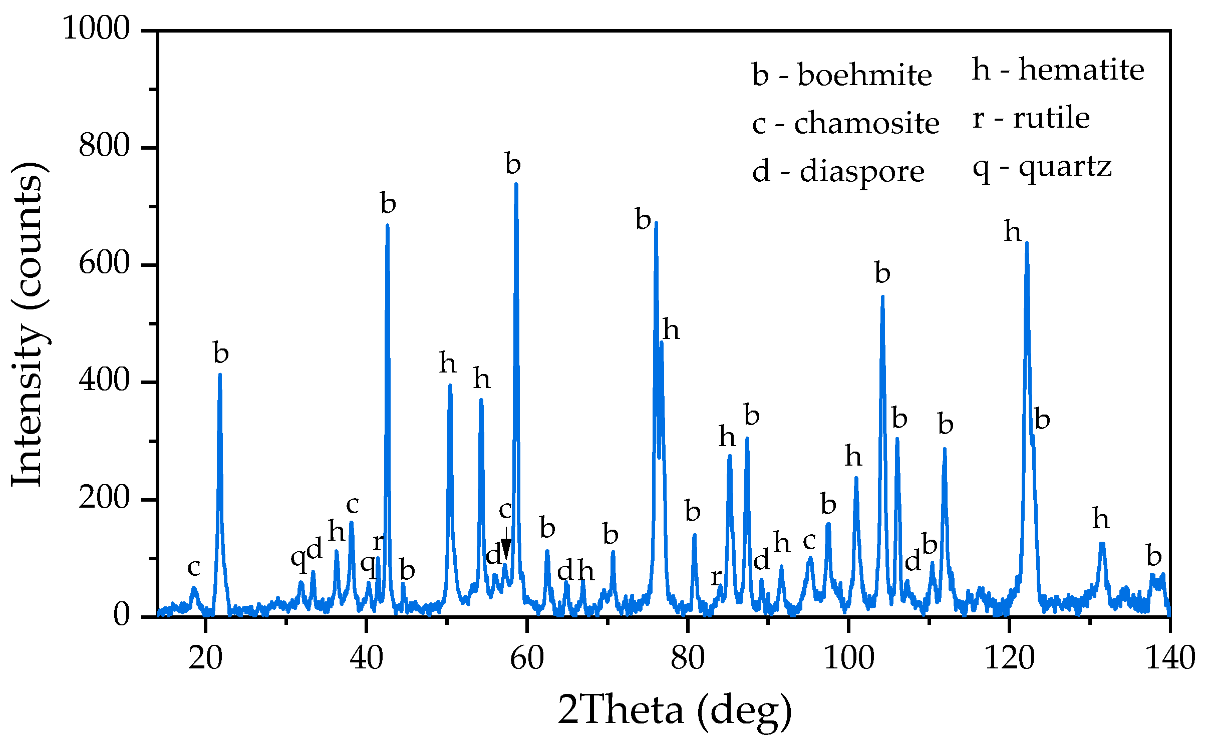
Figure 2.
XRD pattern of magnetite concentrate obtained by leaching of bauxite residue (BR) from the Friguia plant in the presence of (2+) at T = 120 °C, τ = 120 min, CNa2O = 330 g L-1.
Figure 2.
XRD pattern of magnetite concentrate obtained by leaching of bauxite residue (BR) from the Friguia plant in the presence of (2+) at T = 120 °C, τ = 120 min, CNa2O = 330 g L-1.
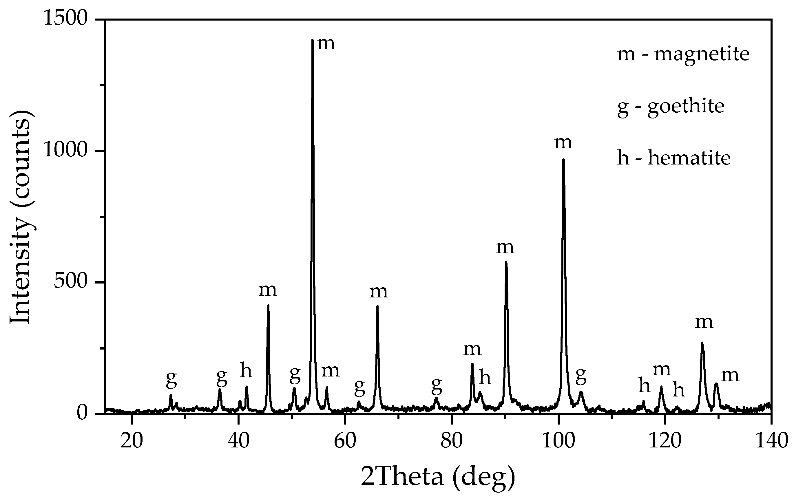
Figure 3.
Schematic view of experimental setups used to study the process of electroreduction of bauxite iron minerals in alkaline media: (a) for experiments in suspension with a plate cathode with constant stirring; (b) for experiments with a bulk cathode (mesh current supply).
Figure 3.
Schematic view of experimental setups used to study the process of electroreduction of bauxite iron minerals in alkaline media: (a) for experiments in suspension with a plate cathode with constant stirring; (b) for experiments with a bulk cathode (mesh current supply).
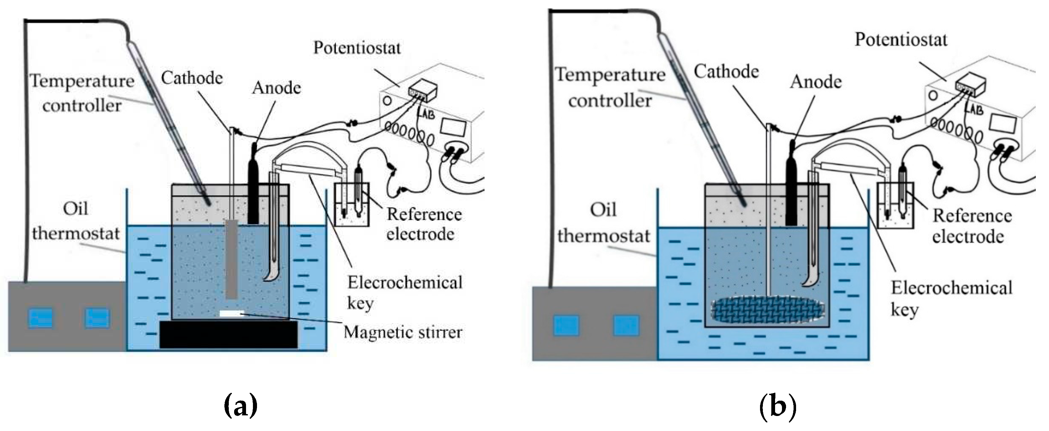
Figure 4.
Dependence of current density on potential during electroreduction of iron minerals in suspension of bauxite in aluminate solution of Bayer process: (a) at different concentrations of solid at 95 °C; (b) at different concentrations of solid at 110 °C; (c) at different temperatures at solid concentration of 300 g L–1.
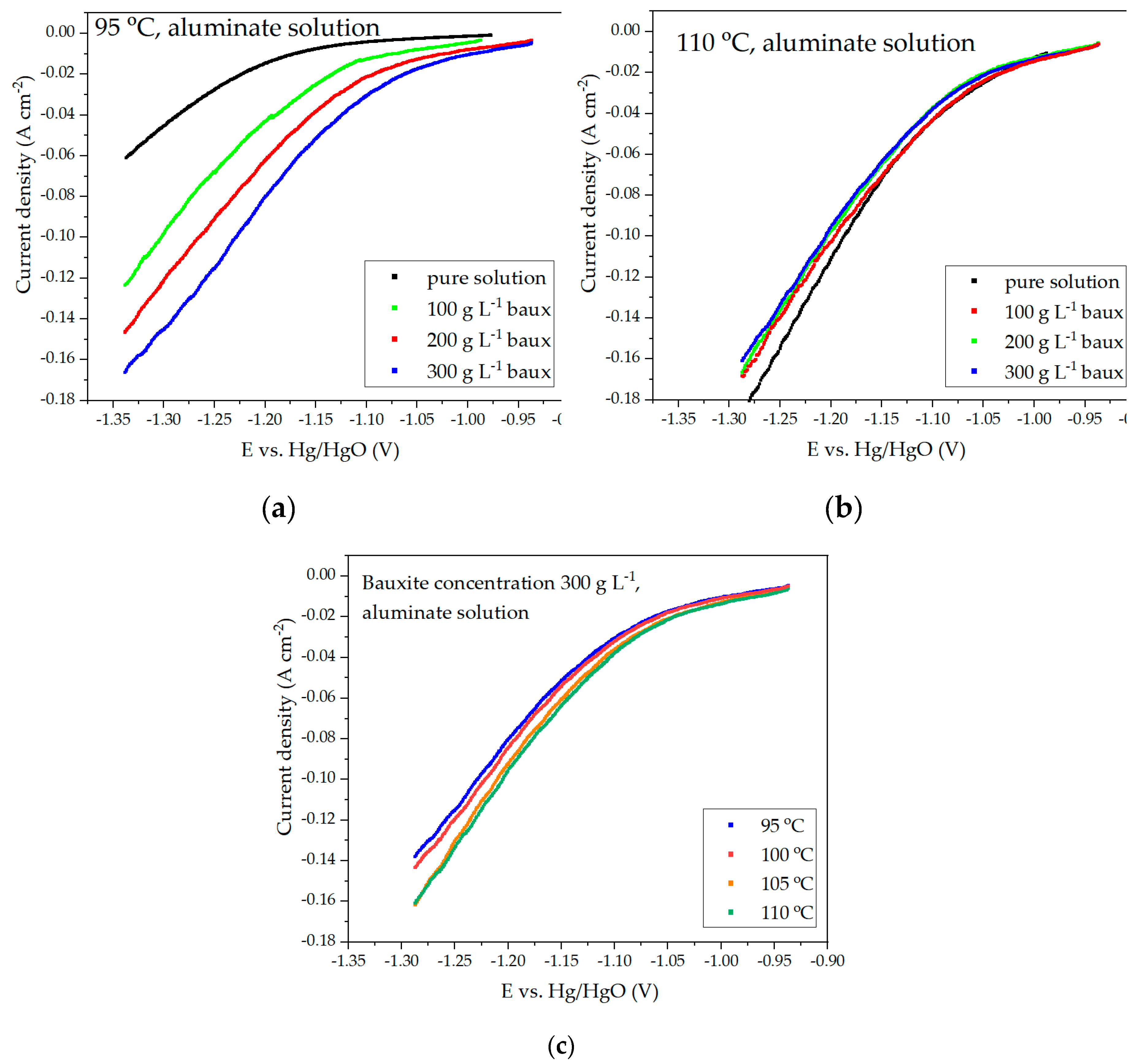
Figure 5.
Results of current efficiency calculations at different temperatures and solid concentrations during the reduction of iron minerals for 2 h using a suspension of bauxite in aluminate Bayer solution.
Figure 5.
Results of current efficiency calculations at different temperatures and solid concentrations during the reduction of iron minerals for 2 h using a suspension of bauxite in aluminate Bayer solution.
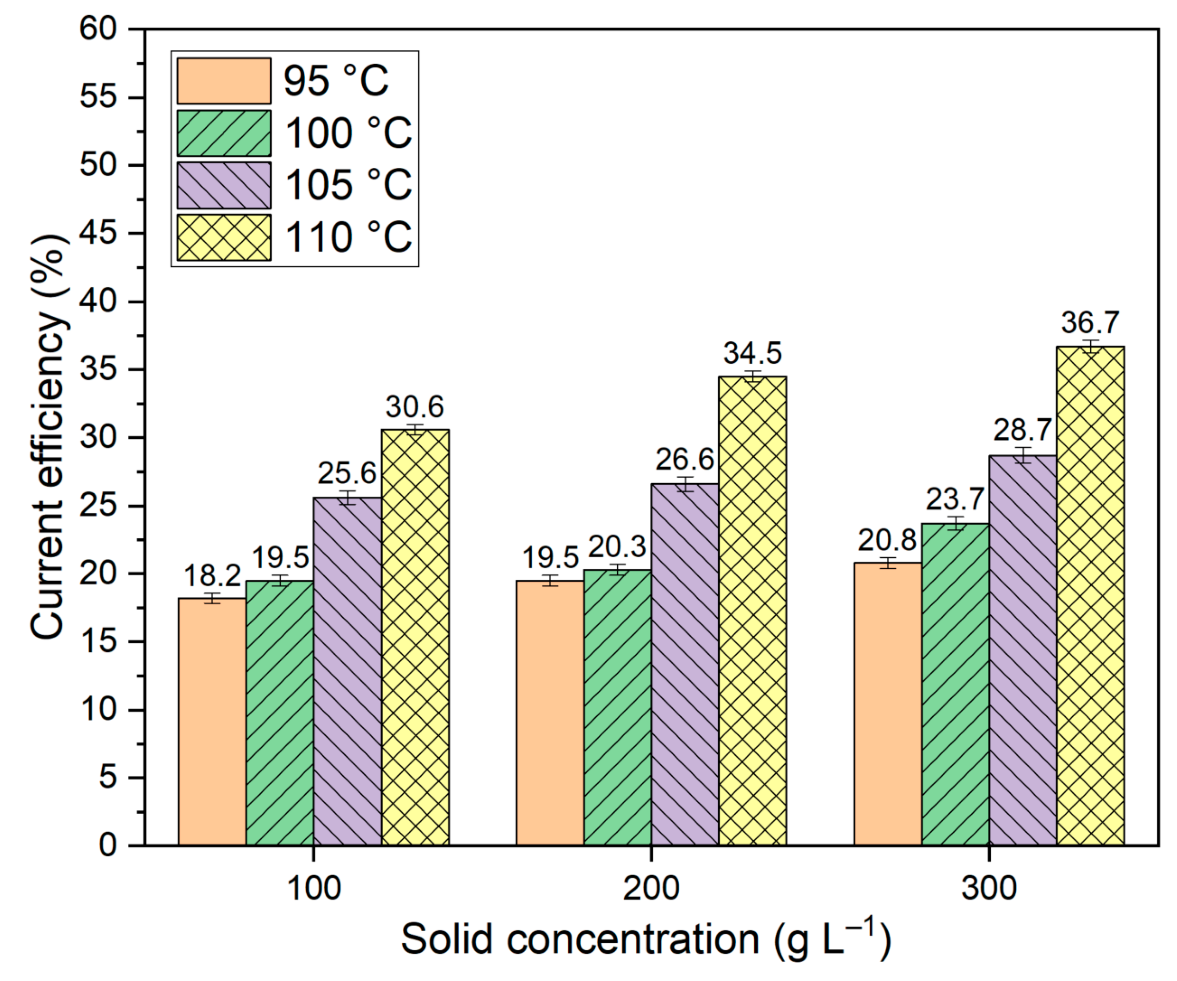
Figure 6.
Dependence of current density on potential during electroreduction of bauxite iron minerals in alkaline solution with concentration of 400 g L–1: (a) cyclic voltammetry (CV) at temperature 120 °C and solid concentration 100 g L–1; (b) CV at temperature 120 °C and solid concentration 300 g L–1; (c) potentiodynamic measurements at temperature 110 °C at different solid concentrations; (d) potentiodynamic measurements at temperature 120 °C at different solid concentrations.
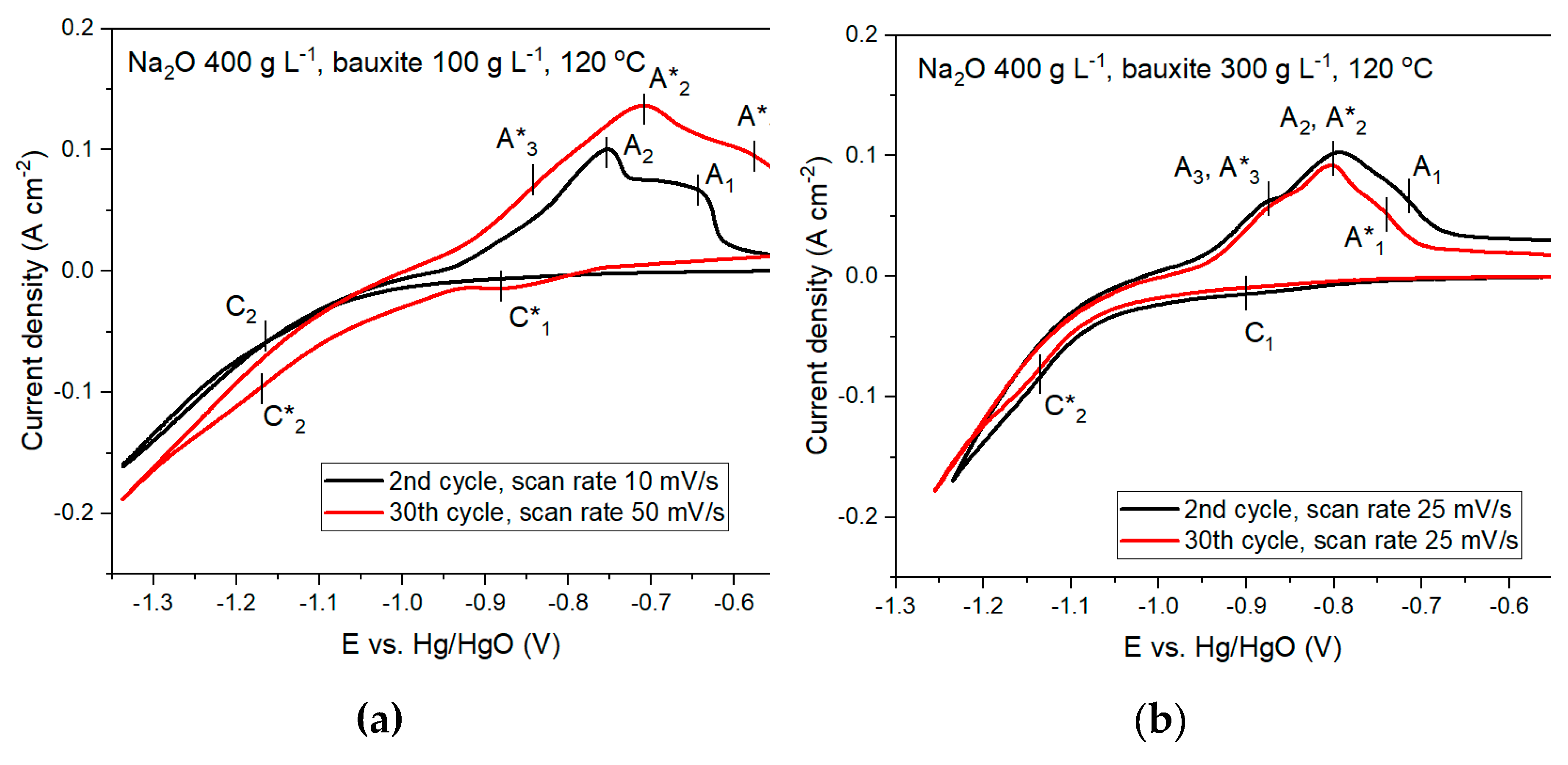
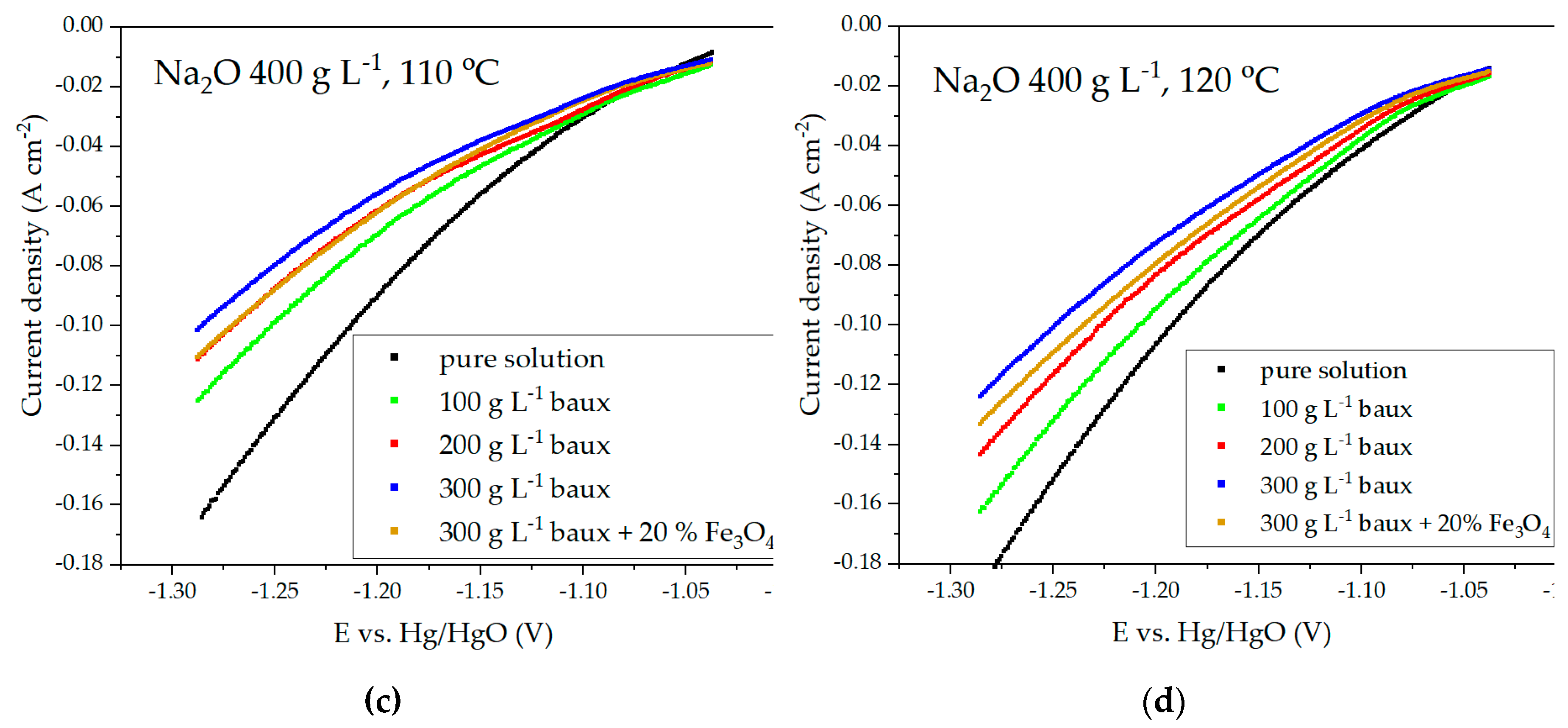
Figure 7.
Mechanism of activating effect of magnetite.
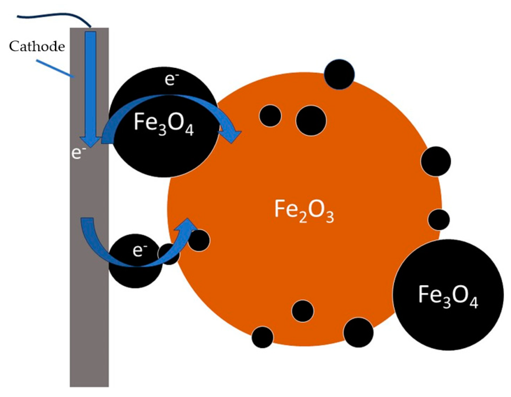
Figure 8.
Results of current efficiency calculations at different temperatures and solid concentrations for iron minerals reduction for 2 h in suspension of bauxite in alkaline solution at a constant potential of -1.15 V.
Figure 8.
Results of current efficiency calculations at different temperatures and solid concentrations for iron minerals reduction for 2 h in suspension of bauxite in alkaline solution at a constant potential of -1.15 V.
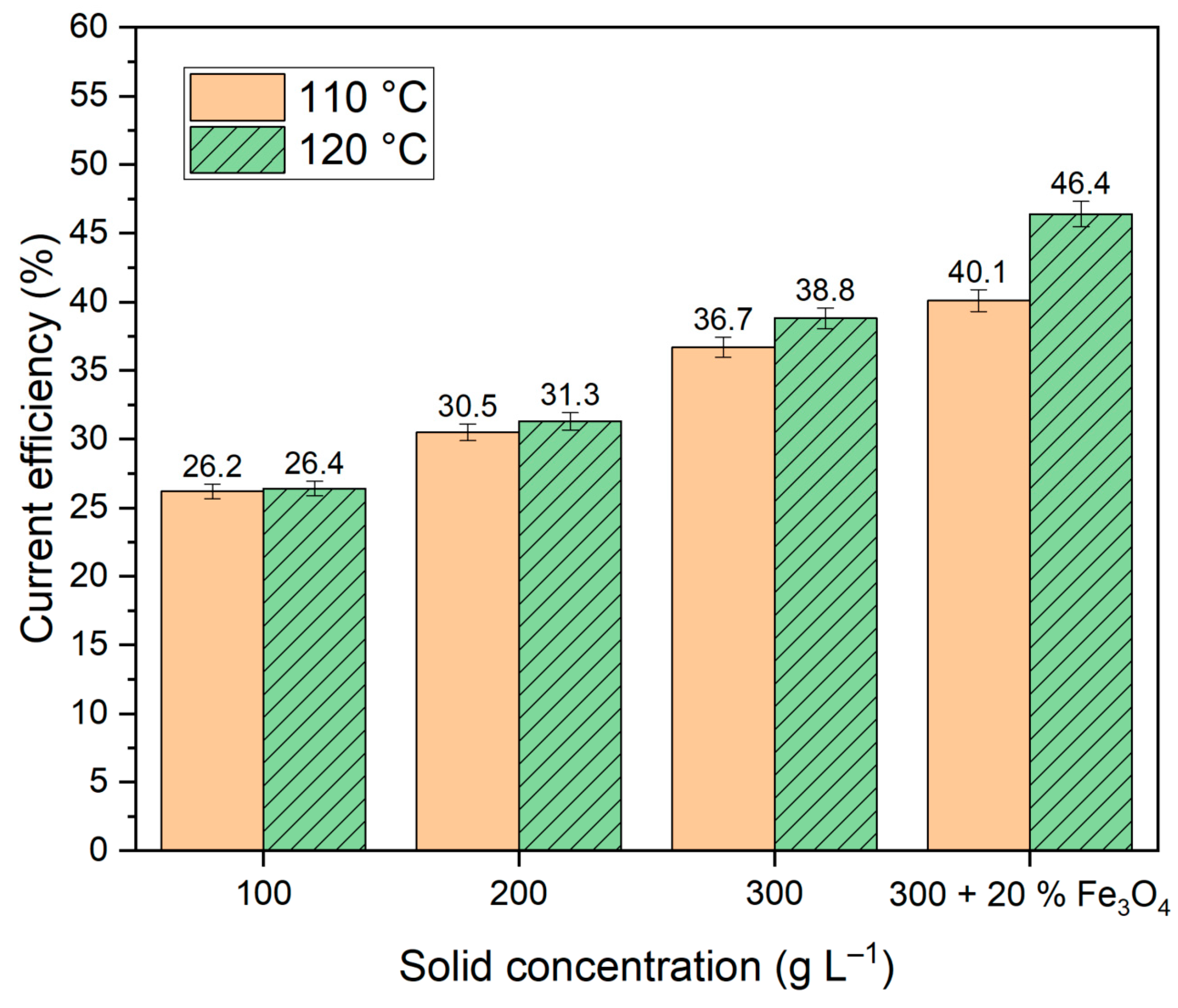
Figure 9.
Results of experiments on electroreduction of bauxite iron minerals using a thickened slurry and a mesh current supply with the area of 110 cm2: (a) dependence of current on potential during electroreduction of bauxite minerals in alkali solution with the concentration of 400 g L–1; (b) dependence of potential at the cathode on electrolysis time at a constant current of 1.945 A.
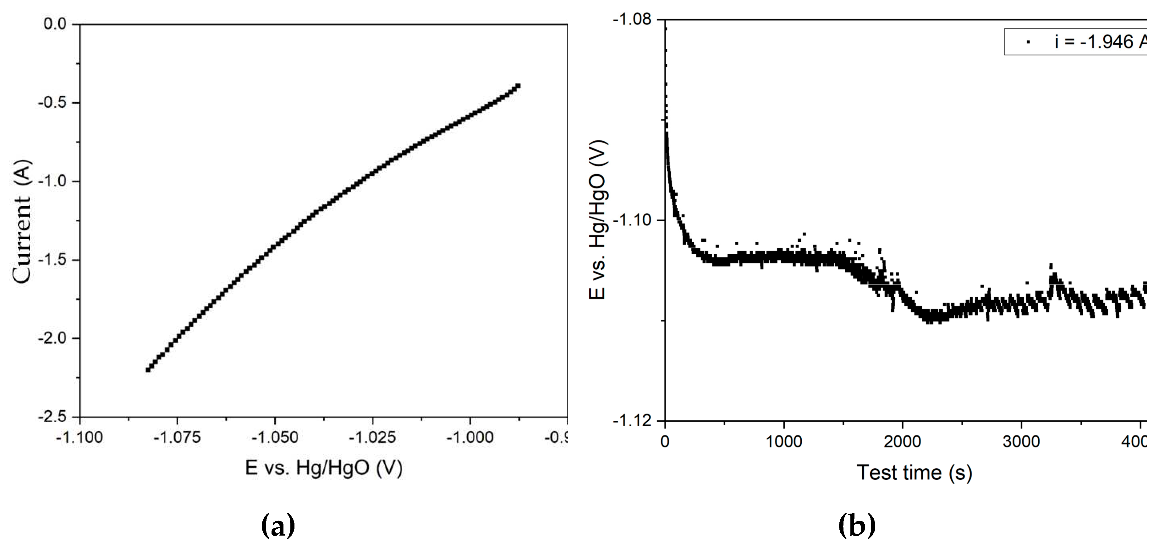
Figure 10.
Effect of electrolysis duration using a 110 cm2 mesh current supply on the degree of iron (3+) species reduction and current efficiency coefficient at 100 g of bauxite per 300 cm3 of alkaline suspension, temperature 120 °C and constant current 1.945 A.
Figure 10.
Effect of electrolysis duration using a 110 cm2 mesh current supply on the degree of iron (3+) species reduction and current efficiency coefficient at 100 g of bauxite per 300 cm3 of alkaline suspension, temperature 120 °C and constant current 1.945 A.
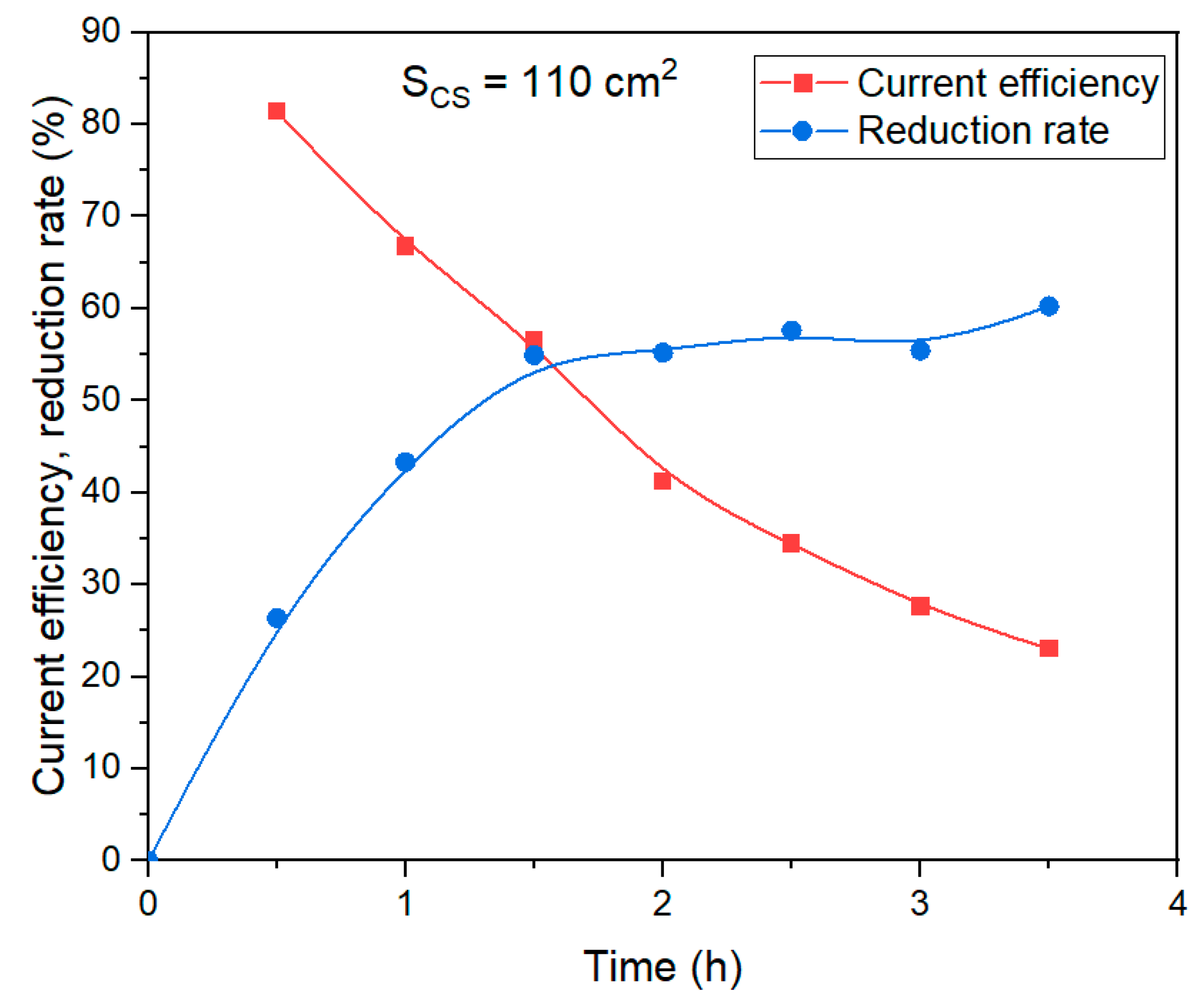
Figure 11.
Results of experiments on electroreduction of bauxite iron minerals using a thickened pulp and a mesh current supply with the area of 40 cm2: (a) dependence of current on potential during electroreduction of bauxite minerals in alkali solution with the concentration of 400 g L–1; (b) dependence of potential at the cathode on electrolysis time at a constant current of 1.945 A.
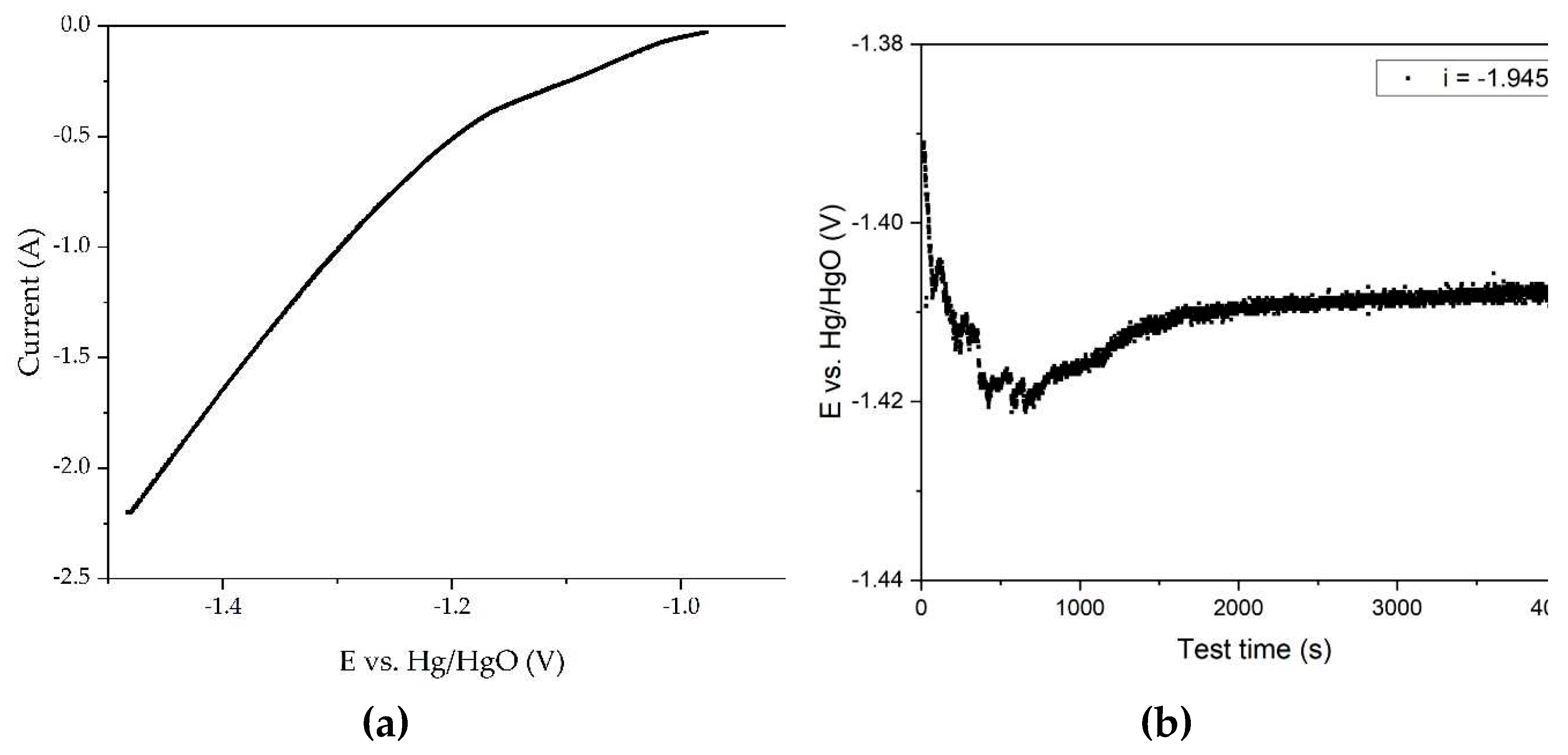
Figure 12.
Effect of electrolysis duration using a 40 cm2 mesh current supply on the degree of iron (3+) species reduction and current efficiency coefficient at 100 g of bauxite per 300 cm3 of alkaline suspension, temperature 120 °C and constant current 1.945 A.
Figure 12.
Effect of electrolysis duration using a 40 cm2 mesh current supply on the degree of iron (3+) species reduction and current efficiency coefficient at 100 g of bauxite per 300 cm3 of alkaline suspension, temperature 120 °C and constant current 1.945 A.
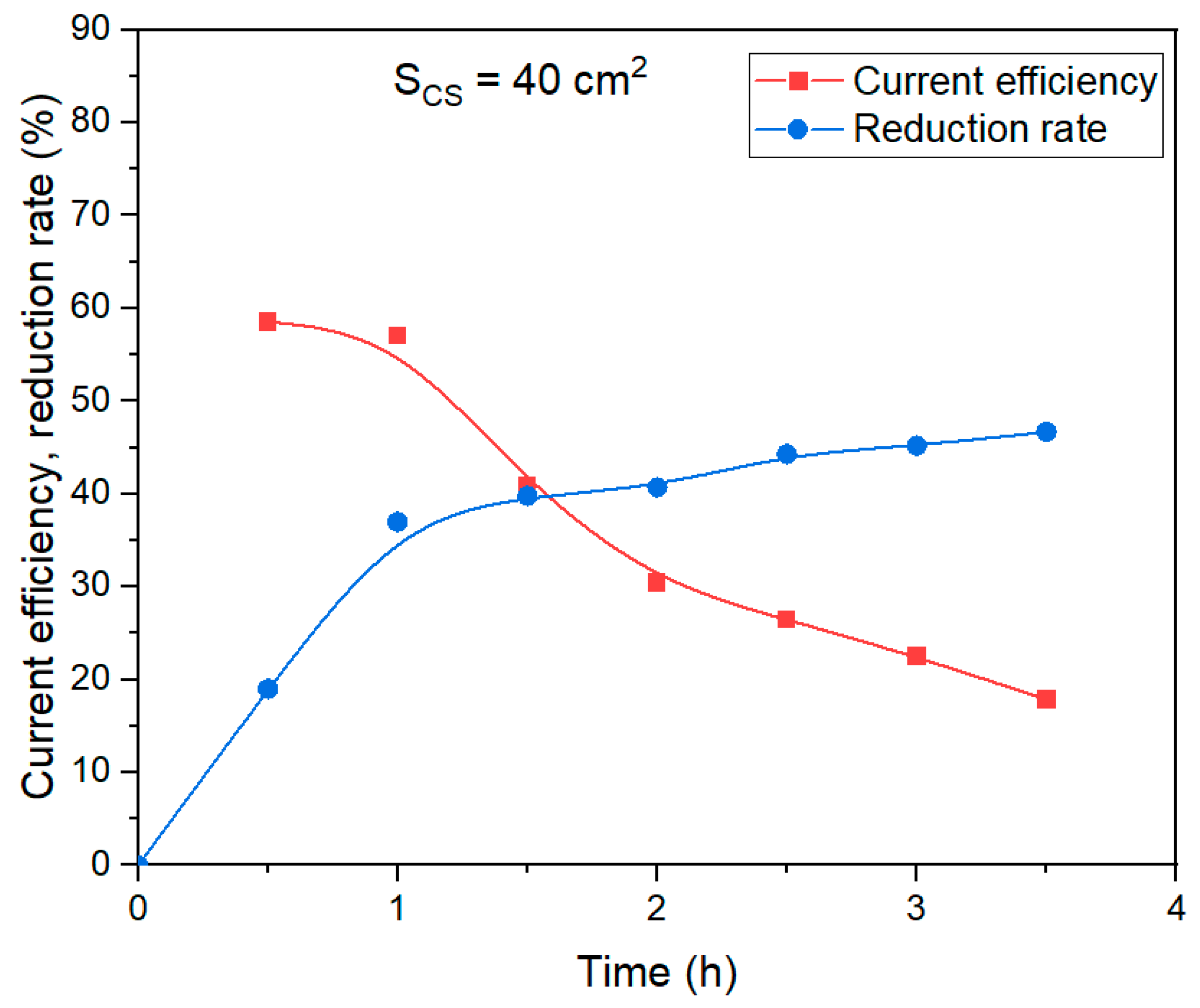
Figure 13.
Results of experiments on electroreduction of bauxite iron minerals using a thickened pulp and a mesh current supply with the area of 75 cm2: (a) dependence of current on potential during electroreduction of bauxite minerals in alkali solution with the concentration of 400 g L–1; (b) dependence of potential at the cathode on electrolysis time at a constant current of 1.945 A.
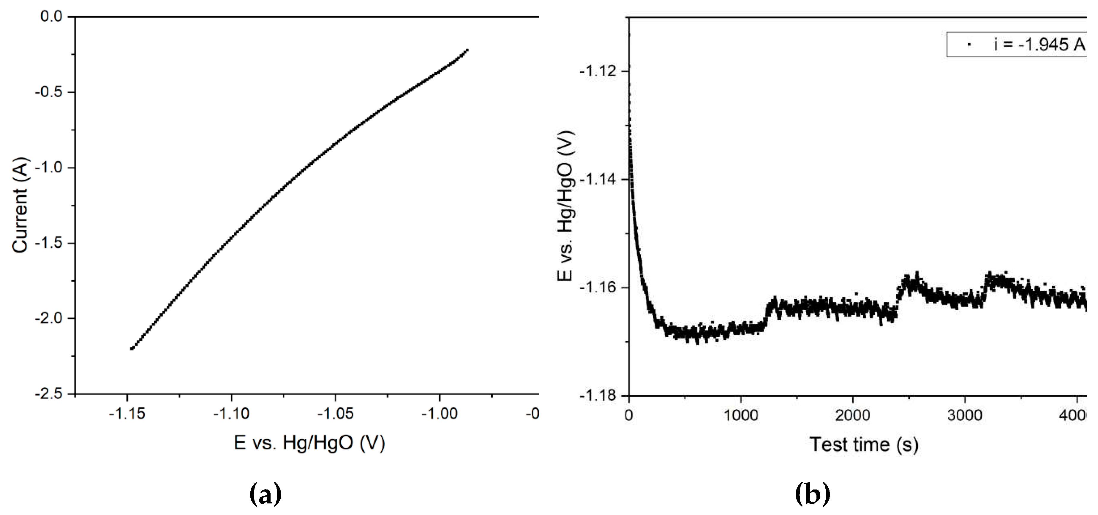
Figure 14.
Effect of electrolysis duration using a 75 cm2 mesh current supply on the degree of iron (3+) species reduction and current efficiency coefficient at 100 g of bauxite per 300 cm3 of alkaline suspension, temperature 120 °C and constant current 1.945 A.
Figure 14.
Effect of electrolysis duration using a 75 cm2 mesh current supply on the degree of iron (3+) species reduction and current efficiency coefficient at 100 g of bauxite per 300 cm3 of alkaline suspension, temperature 120 °C and constant current 1.945 A.
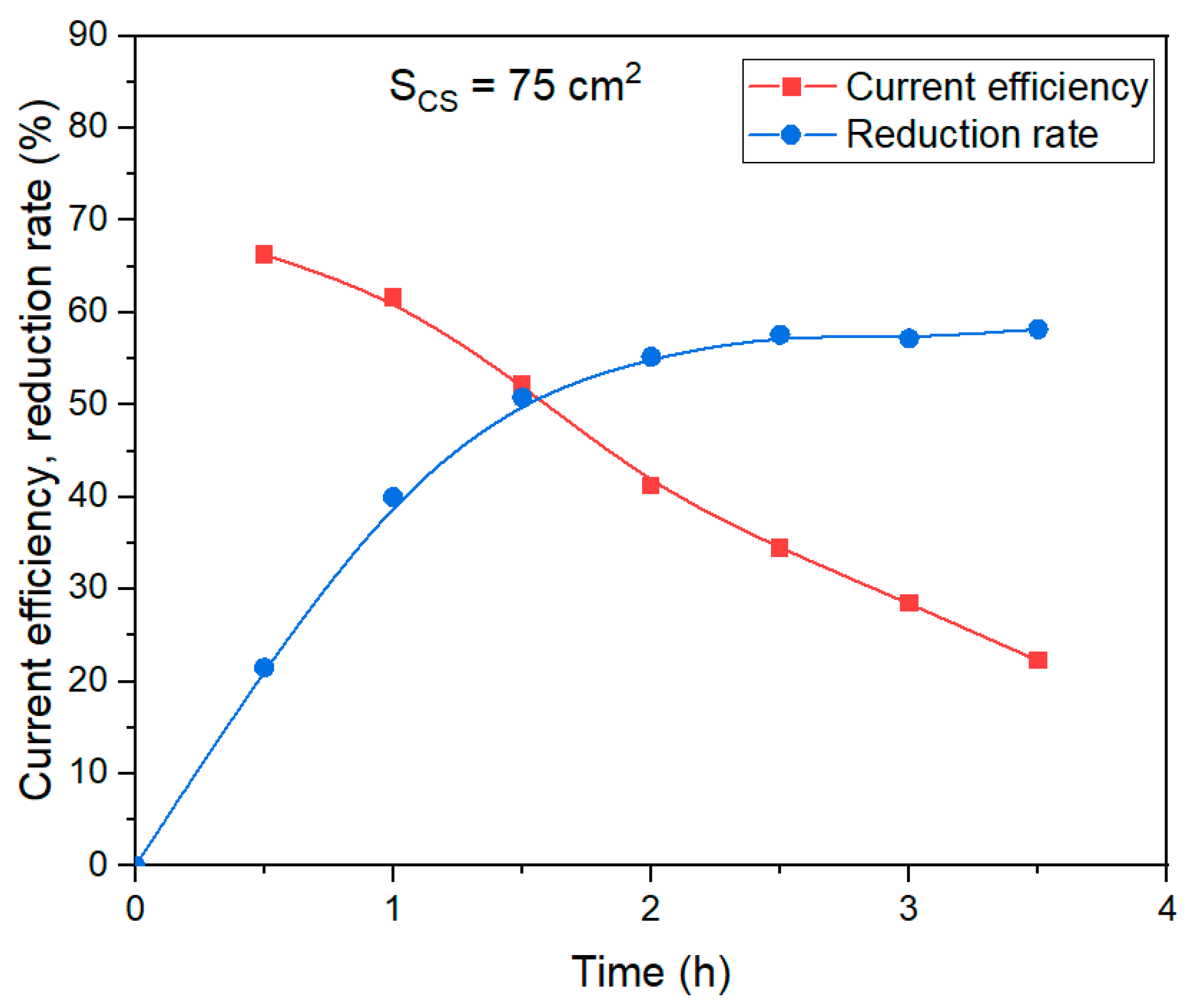
Figure 15.
SEM-image of the precipitate on the surface of the cathode during electrolysis in a suspension of bauxite in aluminate solution at 120 °C and a current density of 0.06 A cm–2.
Figure 15.
SEM-image of the precipitate on the surface of the cathode during electrolysis in a suspension of bauxite in aluminate solution at 120 °C and a current density of 0.06 A cm–2.
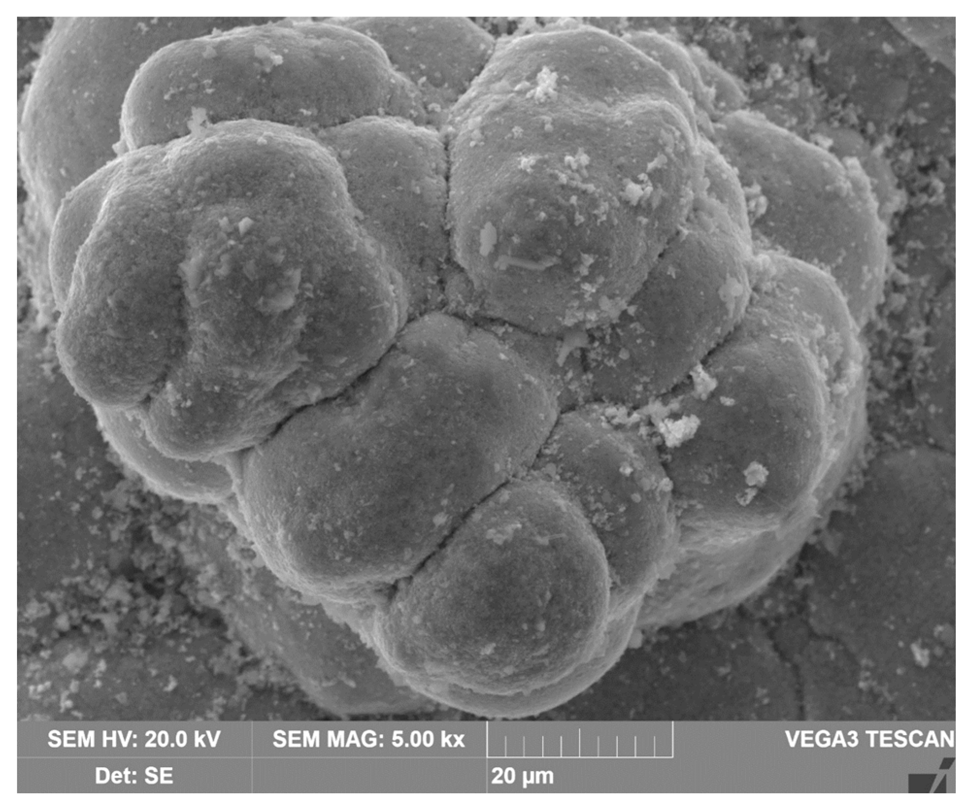
Figure 16.
Maps of the distribution of elements on the surface of the cathode precipitate formed during electrolysis in a suspension of bauxite in aluminate solution at 120 °C and a current density of 0.06 A cm–2: (a) SEM-image of particle surface; (b) Fe distribution map; (c) Al distribution map; (d) Si distribution map.
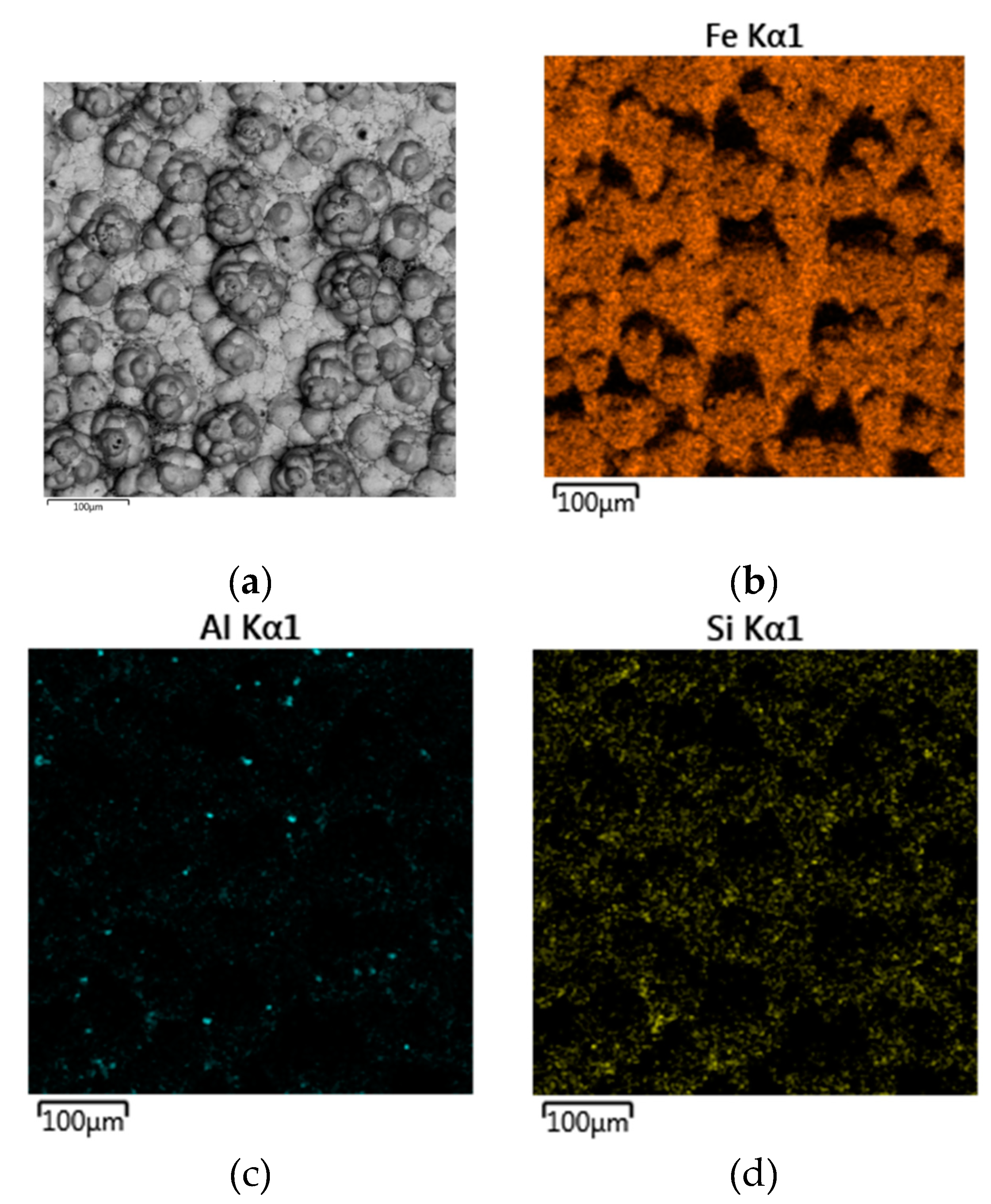
Figure 17.
XRD pattern of the cathode precipitate formed during electrolysis in a suspension of bauxite in aluminate solution at 120 °C and a current density of 0.06 A cm–2.
Figure 17.
XRD pattern of the cathode precipitate formed during electrolysis in a suspension of bauxite in aluminate solution at 120 °C and a current density of 0.06 A cm–2.
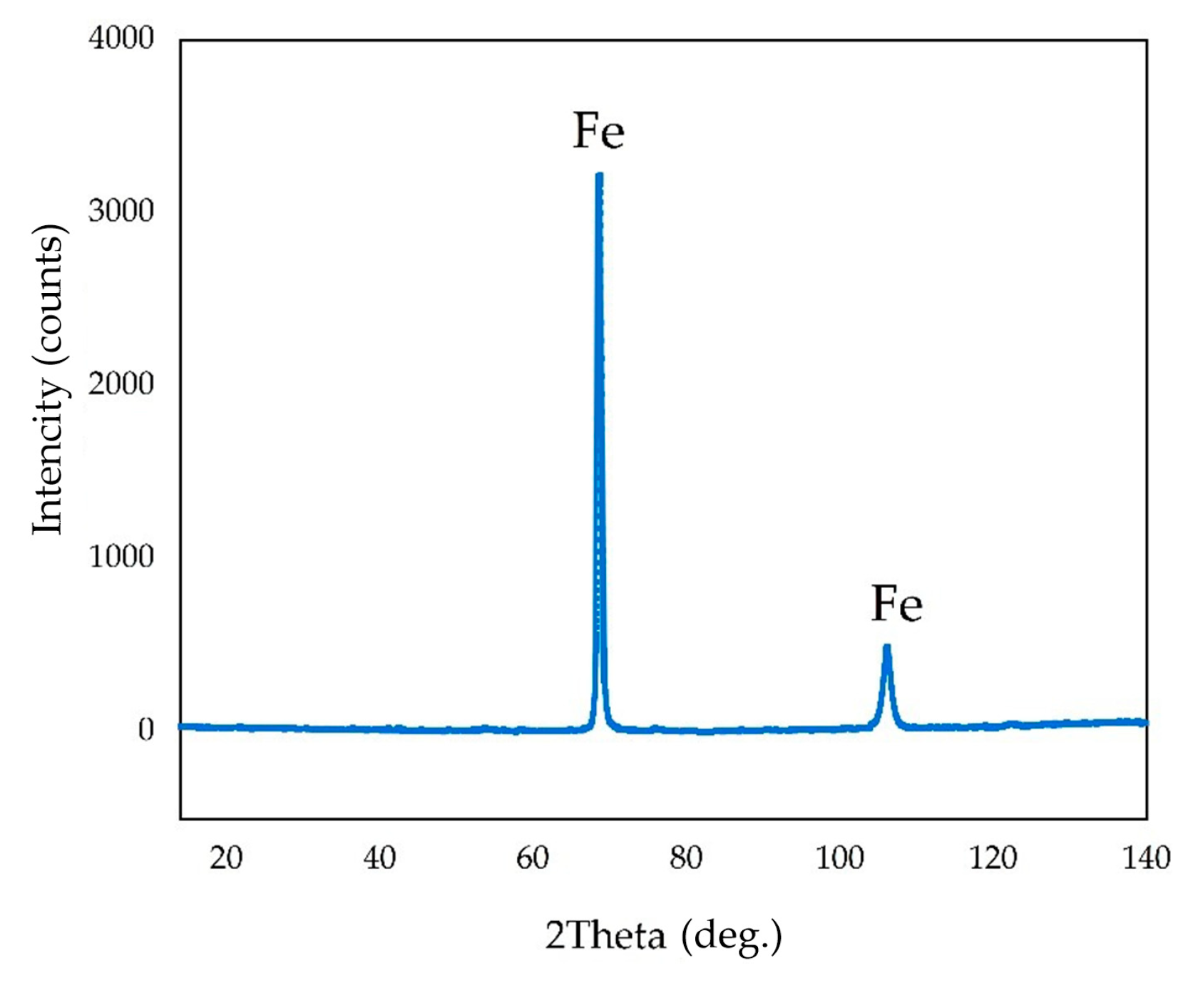
Figure 18.
Results of SEM-EDS analysis of the surface of BR particles obtained after electrolysis with 110 cm2 current supply for 1.17 h: (a) SEM-image of particle surface; (b) Fe distribution map; (c) Al distribution map; (d) Si distribution map.
Figure 18.
Results of SEM-EDS analysis of the surface of BR particles obtained after electrolysis with 110 cm2 current supply for 1.17 h: (a) SEM-image of particle surface; (b) Fe distribution map; (c) Al distribution map; (d) Si distribution map.
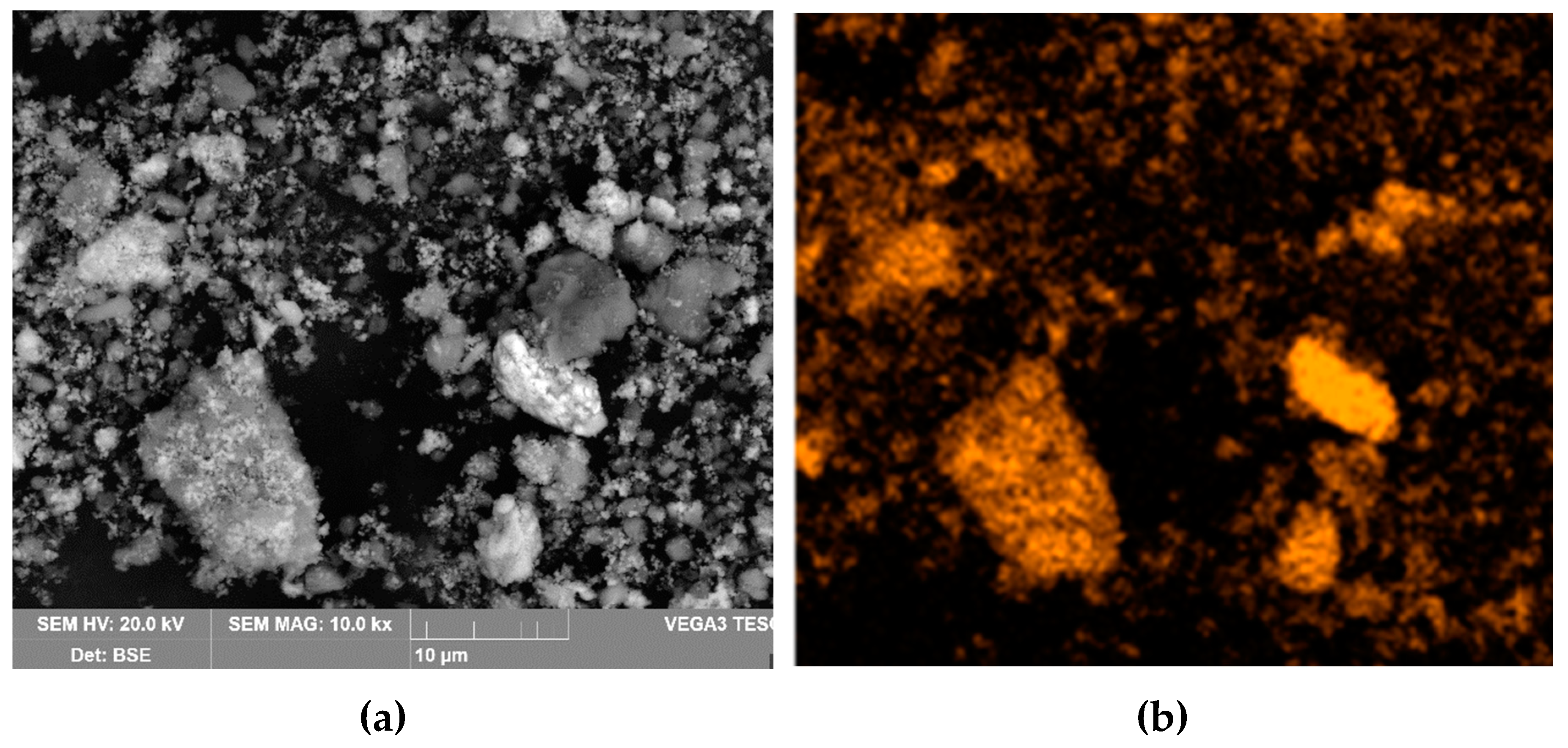
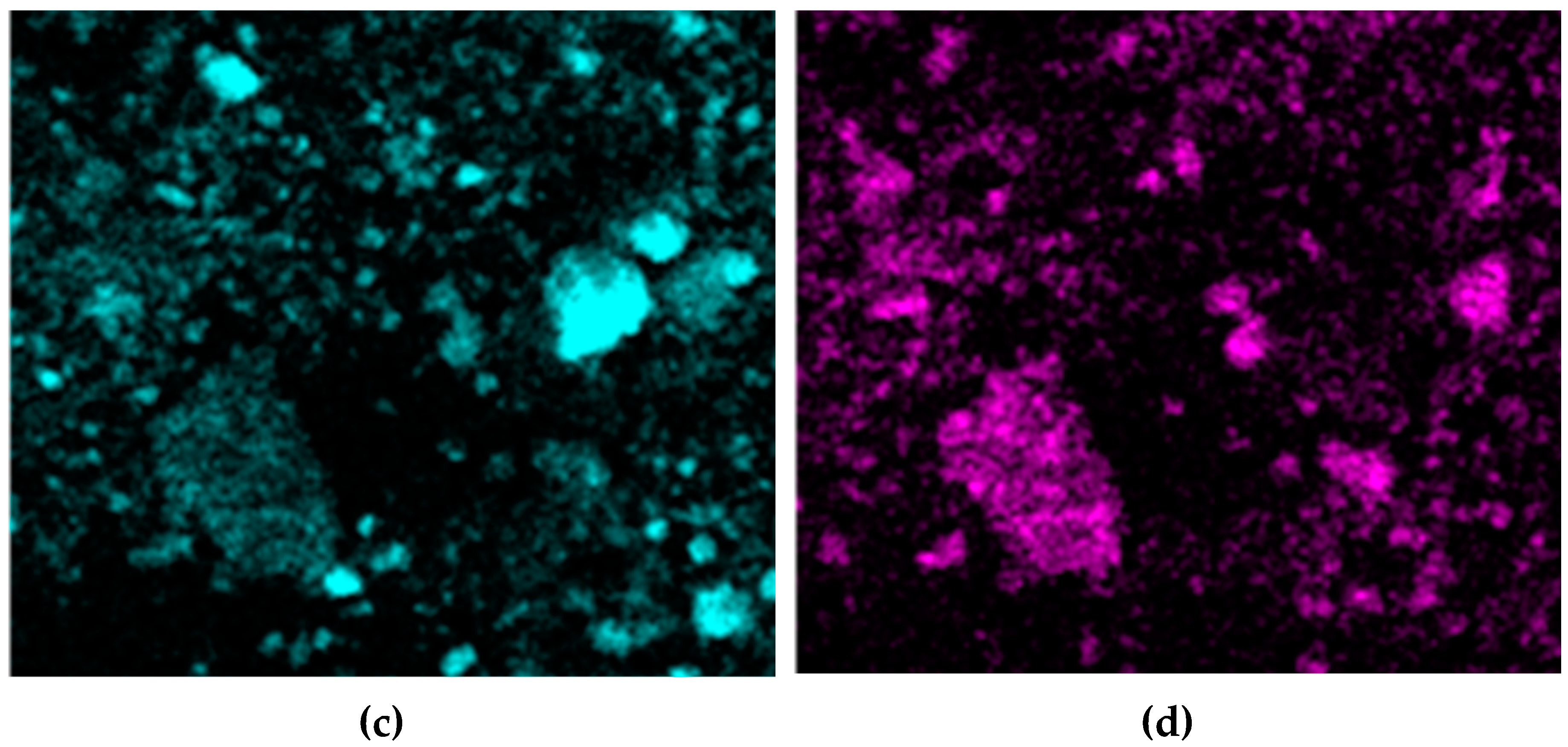
Figure 19.
SEM-images of BR particles with elevated iron content obtained after electrolysis with a 110 cm2 mesh current supply for 1.17 h.
Figure 19.
SEM-images of BR particles with elevated iron content obtained after electrolysis with a 110 cm2 mesh current supply for 1.17 h.
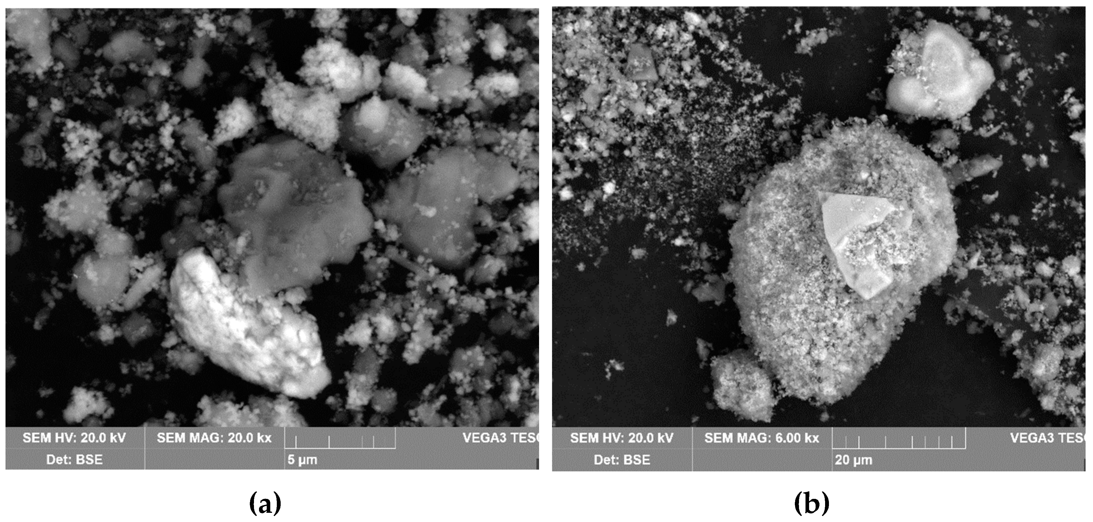
Figure 20.
XRD pattern of: (a) raw bauxite; (b) solid residue obtained after electrolysis with a bulk cathode for 1.17 h at an average potential of –1.41 V; (c) BR obtained after leaching of solid residue from electrolysis with a bulk cathode and a potential of –1.41 V; (d) red mud obtained after electrolysis with a bulk cathode for 1.17 h at an average potential of –1.07 V
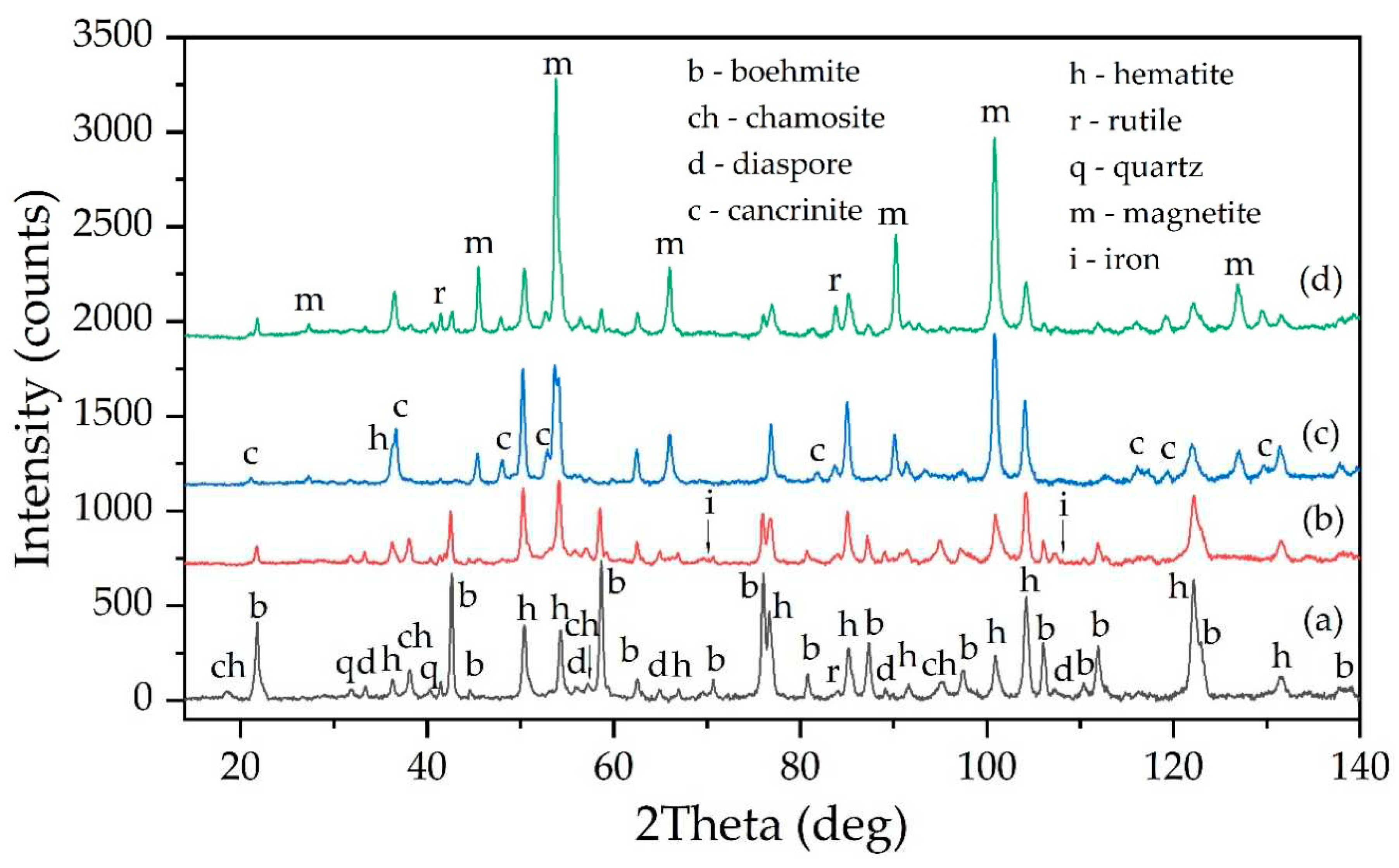
Figure 21.
Microphotograph of elemental iron detected in the solid residue of electrolysis with a 40 cm2 mesh current collector and the result of energy dispersive analysis performed on the particle surface.
Figure 21.
Microphotograph of elemental iron detected in the solid residue of electrolysis with a 40 cm2 mesh current collector and the result of energy dispersive analysis performed on the particle surface.
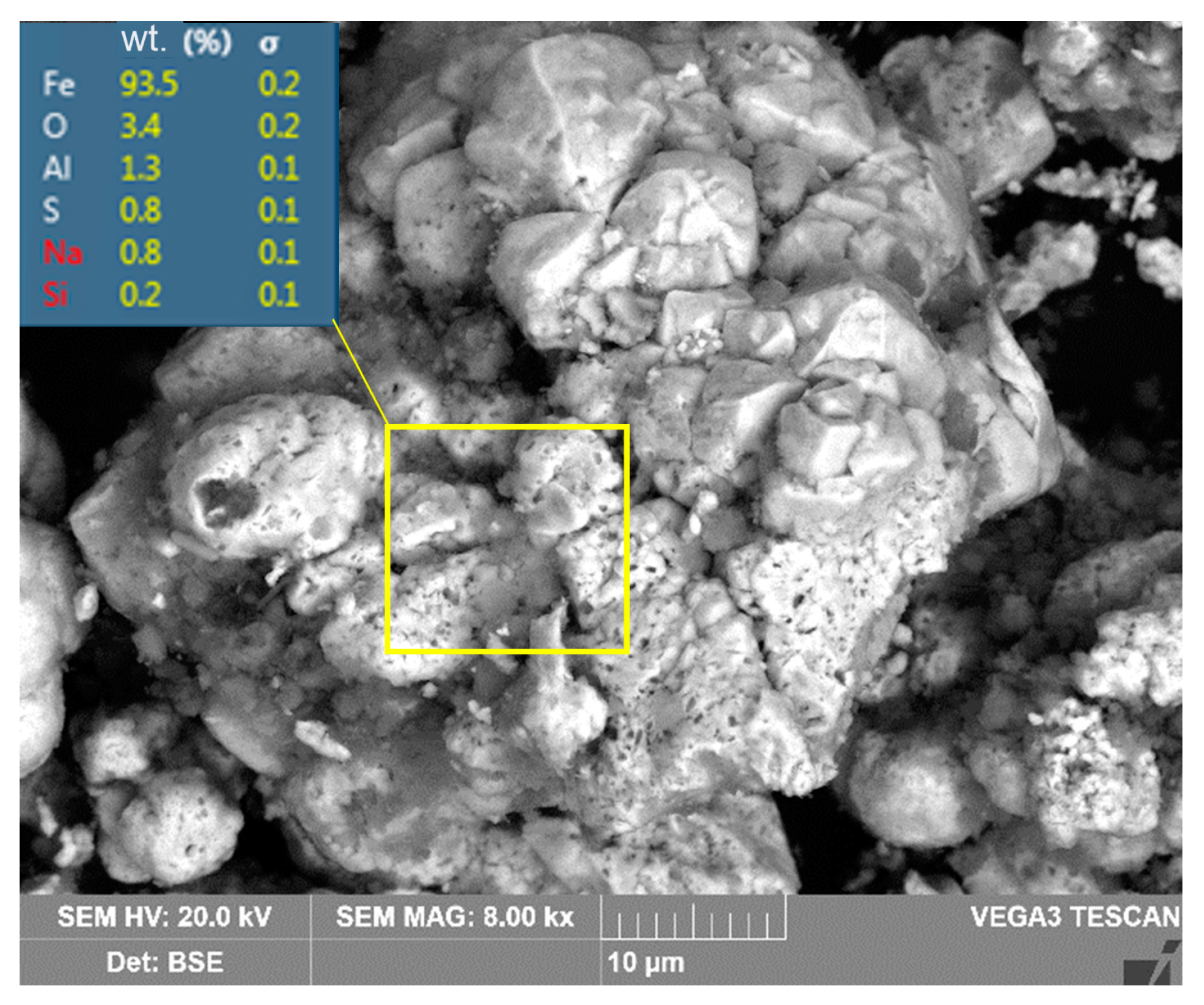
Figure 22.
Results of SEM-EDS analysis of the surface of BR particles obtained after electrolysis with a 40 cm2 mesh current supply for 1.17 h and subsequent leaching by the Bayer process: (a) SEM-image of the surface of BR particles; (b) map of element distribution on the particles surface.
Figure 22.
Results of SEM-EDS analysis of the surface of BR particles obtained after electrolysis with a 40 cm2 mesh current supply for 1.17 h and subsequent leaching by the Bayer process: (a) SEM-image of the surface of BR particles; (b) map of element distribution on the particles surface.
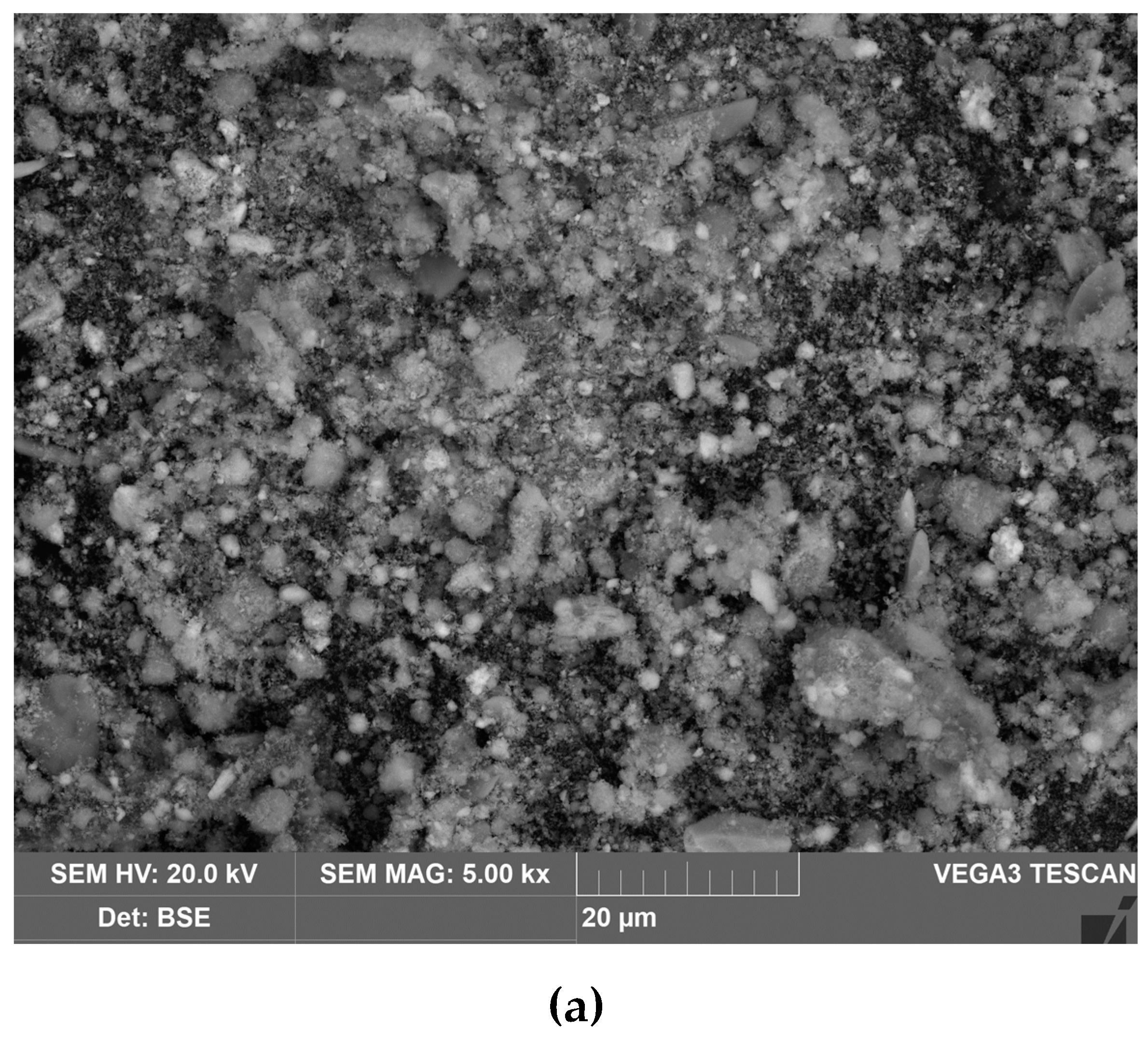
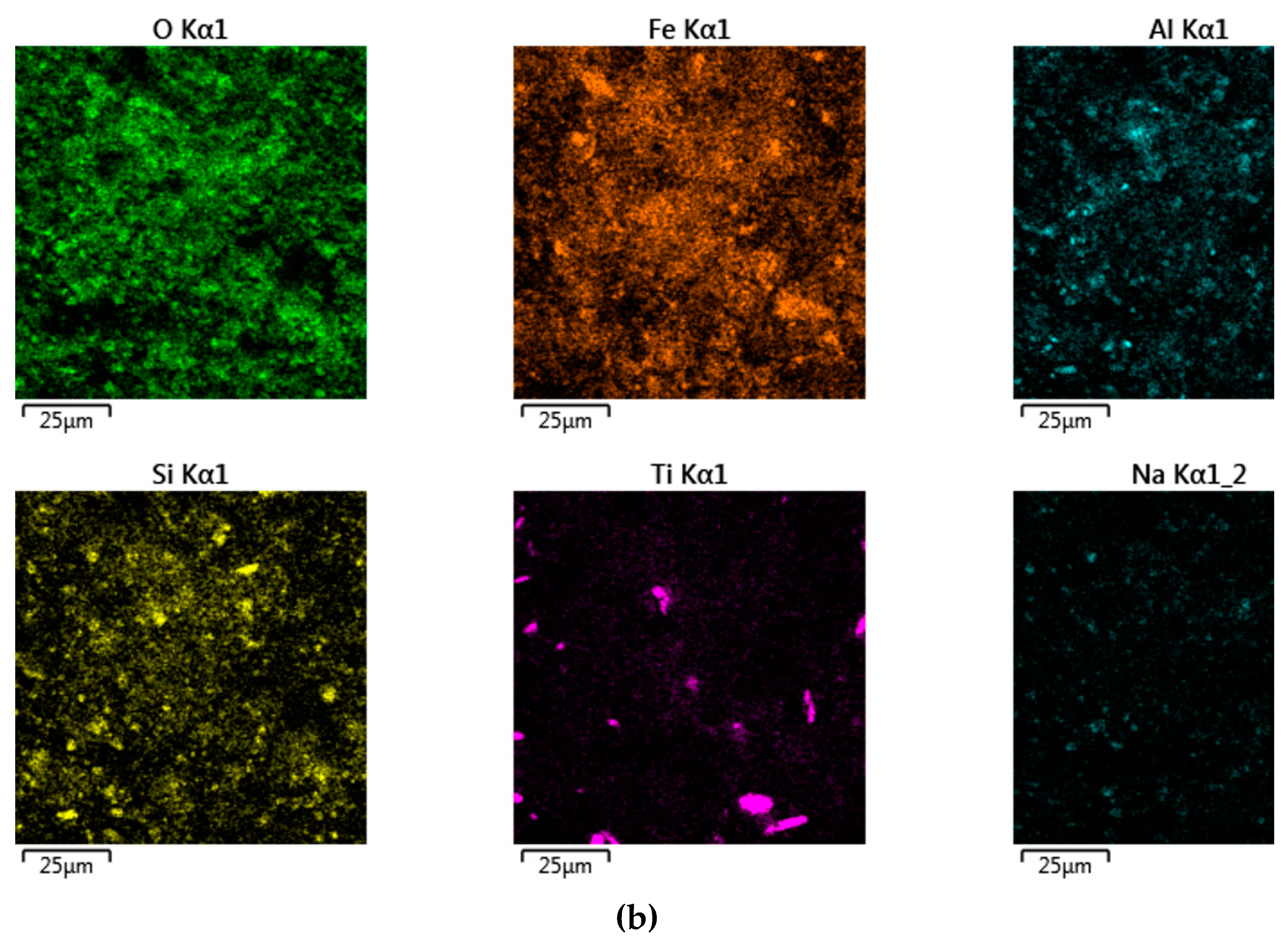
Figure 23.
Results of SEM-EDS analysis of the surface of coarse BR particle obtained after electrolysis with a 110 cm2 mesh current supply: (a) SEM-image of the surface of BR particle at magnitude x1000; a) SEM-image of the surface of BR particle at magnitude x5000; (c) map of element distribution on the particle surface.
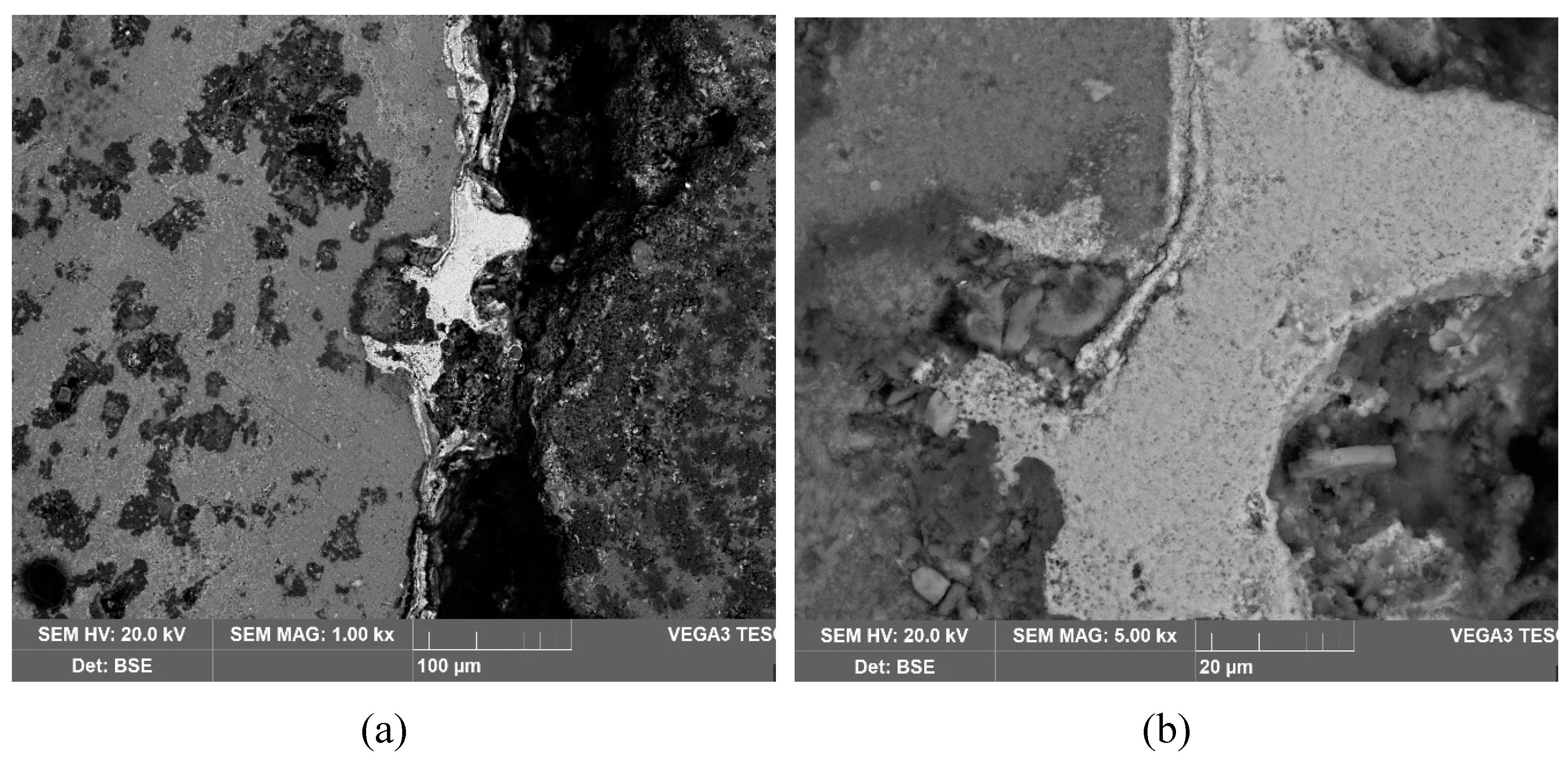
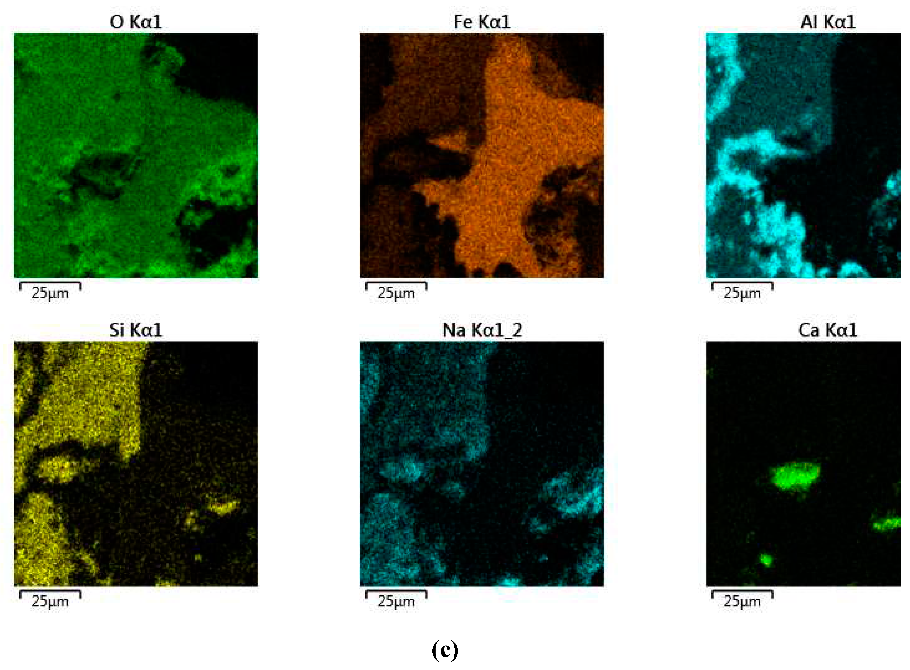

Table 1.
Elemental composition of the raw bauxite, wt. %
| Al | Fe | Si | Ti | Ca | Mn | Mg | K | Na | O |
|---|---|---|---|---|---|---|---|---|---|
| 27.64 | 18.03 | 3.02 | 1.60 | 0.60 | 0.41 | 0.28 | 0.17 | 0.05 | 47.51 |
Table 2.
The elemental composition of the magnetite concentrate obtained after reductive leaching of the Friguia alumina refinery bauxite residue (BR), wt. %.
Table 2.
The elemental composition of the magnetite concentrate obtained after reductive leaching of the Friguia alumina refinery bauxite residue (BR), wt. %.
| Fe | Si | Ti | Al | Na | O | Other |
|---|---|---|---|---|---|---|
| 69.55 | 0.34 | 1.01 | 0.15 | 0.24 | 27.81 | 0.90 |
Table 3.
Elemental composition of BR obtained after electrolysis with 110 cm2 current supply for 1.17 h, wt. %.
Table 3.
Elemental composition of BR obtained after electrolysis with 110 cm2 current supply for 1.17 h, wt. %.
| TFe* | Fe(2+) | Al | Si | Ti | Ca | Mn | Mg | Na | K | O |
|---|---|---|---|---|---|---|---|---|---|---|
| 42.13 | 6.37 | 8.07 | 2.53 | 2.46 | 1,29 | 0.74 | 0.76 | 1.62 | 0,003 | 39.88 |
* TFe – total iron content
Table 4.
Elemental composition of the solid residue obtained after electrolysis with a 40 cm2 mesh current supply for 1.17 h and of the BR after its leaching with alkali aluminate solution at T = 250 °C, τ = 30 min, CNa2O = 300 g L–1, CAl2O3 = 150 g L–1.
Table 4.
Elemental composition of the solid residue obtained after electrolysis with a 40 cm2 mesh current supply for 1.17 h and of the BR after its leaching with alkali aluminate solution at T = 250 °C, τ = 30 min, CNa2O = 300 g L–1, CAl2O3 = 150 g L–1.
| Sample | TFe | Fe(2+) | Al | Si | Ti | Ca | Mn | Mg | Na | K | O |
|---|---|---|---|---|---|---|---|---|---|---|---|
| Solid residue of electrolysis | 37.91 | 4.39 | 15.36 | 1.74 | 2.28 | 1.47 | 0.52 | 0.51 | 0.42 | 0.005 | 39.79 |
| BR | 57.65 | 8.47 | 1.33 | 1.12 | 3.72 | 1.06 | 0.70 | 0.63 | 0.46 | 0.003 | 33.33 |
Disclaimer/Publisher’s Note: The statements, opinions and data contained in all publications are solely those of the individual author(s) and contributor(s) and not of MDPI and/or the editor(s). MDPI and/or the editor(s) disclaim responsibility for any injury to people or property resulting from any ideas, methods, instructions or products referred to in the content. |
© 2023 by the authors. Licensee MDPI, Basel, Switzerland. This article is an open access article distributed under the terms and conditions of the Creative Commons Attribution (CC BY) license (https://creativecommons.org/licenses/by/4.0/).
Copyright: This open access article is published under a Creative Commons CC BY 4.0 license, which permit the free download, distribution, and reuse, provided that the author and preprint are cited in any reuse.


