1. Introduction
Rock bursts are among the most devastating in an engineering project due to the extensive safety risks to the mine, workers, and surface infrastructure. Researchers have performed extensive research on preventing rock bursts, and stress release has become one of the effective technical ways to solve this engineering problem[
1]. Stress relief and seismicity monitoring are essential to rock burst prevention during coal mining[
2] and deep underground construction under high horizontal stress conditions[
3].
Many experts have studied stress relief as a preventative measure. Liu[
4] achieved stress relief by optimizing the pre-split blasting spherical cartridge parameters. Yang[
5] compared equivalent blasting effects to determine the law of crack propagation and stress wave attenuation in coal by high-pressure air blasting. Tu[
6] optimized the blasting parameters, and the truncated blasting plan achieved an excellent crack-forming effect, and the estimation model of blast-broken and cracked areas was also studied and showed the most critical parameters affecting these two areas. Ge[
7] proposed a similar model of rock blasting under a unidirectional load with transparent model materials. It was shown that the initial stress suppressed the propagation length and velocity of the main radial cracks. Lv[
8] utilized the empty hole effect to generate stress concentration between the borehole and the empty hole to achieve the effect of directional cracking. Liu[
9] found that the stress-relieving effect of a water medium is greater than that of the air-filled medium by comparing the uncoupled blasting test of water-filled and air-filled. Chen[
10] used LS-DYNA to simulate the development of cracks between boreholes and revealed the rationality of optimizing blasting parameters. Pan[
11] established “F-shaped” and “L-shaped” stress source structure models of the deep gob-side multi-pillar entry and revealed the occurrence mechanism of rock burst. Zhang[
12] proposed a new combined support strategy of optimizing roadway layout, designing impact-resistant support systems, and local reasonable pressure relief with good application results. Luo[
13] pointed out that the non-penetrating fracture zone formed by pressure relief blasting increases the stress concentration of the surrounding rock of the roadway, which is unfavorable for engineering safety. Chen[
14] analyzed the drilling pressure relief effect of surrounding rock at different borehole positions and borehole depths. The stress evolution process of surrounding rock after excavation was obtained.
The above research provided several methods for alleviating the rock burst risk of the cavern, but it mainly focused on parameter optimization and rock-breaking mechanism research. There is little research on the impact of rock blasting range on stress release. Therefore, this paper combines numerical simulation and field tests to analyze the range of rock damage zone, stress propagation characteristics, and energy distribution under the action of high-stress confining pressure. The research results have a guiding significance for preventing and controlling disasters such as rock bursts.
2. Theoretical analysis
2.1. Mechanism of rock breaking
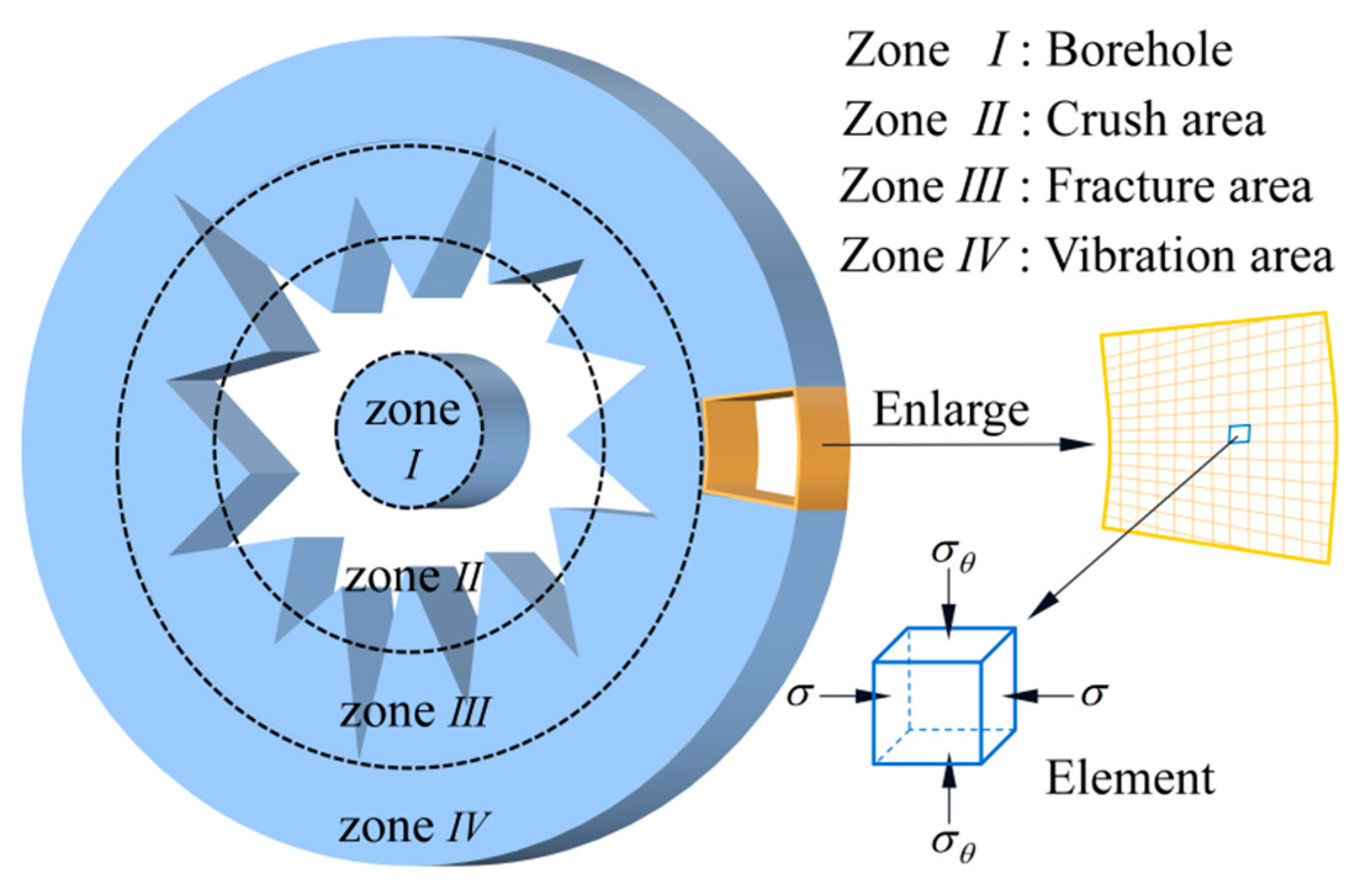
The crushing behavior of rock by blasting is a complex energy transfer process. The crushing effect depends on the mechanical property parameters of rock and is also affected by other factors such as the surrounding environment, in-situ stress, and inertia effects. The effect of rock breakage after blasting can be summarized as follows: the reflection of shock wave causes rock tensile damage, the expansion of explosion gas leads to compressive and shear failure, and both factors influence the formation of the final crack. This view is considered comprehensively, and the obtained results align with the actual situation, which most blasting workers recognize. Therefore, it is believed that the shock wave plays a vital role in the formation of initial radial cracks in the rock, and the formation of a large number of broken rock circles is the result of the action of the blasting gas[
15]. The failure zone and stress state of rock blasting is shown in
Figure 1, where
is the radial compressive stress and
is the tangential tensile stress.
2.2. Theoretical analysis of rock blasting
2.2.1. Radius calculation of crush zone
According to the Von-Mises yield criterion[
16], the three principal stresses of the rock fracture zone are
,
and the stress in the
Z axis
. The rock begins to break when the equivalent stress
greater than the dynamic compressive strength of the rock
. At this time, the initial impact pressure acting on the hole wall is
[
17]:
where
r0 is the radius of the cartridge radius, m;
r1 is the radius of the borehole;
n is the pressure increase parameter when the detonation product collision with the borehole wall,
n=8~11;
D is the detonation wave velocity, m·s
-1;
is the density of explosive, kg·m
-3.
Due to the rock impedance, the shock wave attenuates into a stress wave. The propagation velocity
D decreases to the sound velocity
C1 of the rock mass, and the compressive stress generated by the stress wave is
:
where
is the density of rock, kg·m
-3;
u1 is the movement speed of rock, m·s
-1.
For columnar charge, the relationship between the radial compressive stress
and the radius
r of stress wave propagation can be expressed as:
where
is the shock wave attenuation index.
The equivalent stress
σs when damage occurs can be expressed as:
where
is the dynamic Poisson’s ratio of the rock;
is the static compressive strength of the rock, MPa;
is the loaded strain rate.
Based on the above formulas, the radius
of the crushing area is given by:
Many theoretical and semi-empirical formulas have been proposed to estimate the relationship between the shock wave propagation radius
and
. Under the uncoupled charge, the relationship proposed to estimate the radius ratio is as follows:
The calculation formula of the radius of the crushing area
R1 is given as follows:
2.2.2. Radius calculation of fracture zone
When the tangential stress exceeds the dynamic tensile strength of the rock, the dense fracture zone begins to form around the crushed zone is initiated. Generally, the range of rock fracture zone includes the main tensile failure fracture generated by stress wave and the secondary expansion of the main fracture caused by explosion gas. The dynamic tensile strength
can be expressed as:
The radius of the fracture zone
generated by the stress wave can be expressed as:
However, when
, the dynamic tensile strength
can be expressed as:
The radius of the fracture zone is as follows:
It can be seen from the above formula that the pressure generated by the explosion gas decreases exponentially as the distance from the borehole increases. When the explosion gas breaks through the fracture zone of the stress wave, the secondary expansion length
β can be expressed as:
where
is the fracture tip stress, MPa.
Therefore, the radius of the fracture zone
R2 is:
3. Simulation of hard roof blasting
3.1. Numerical Model
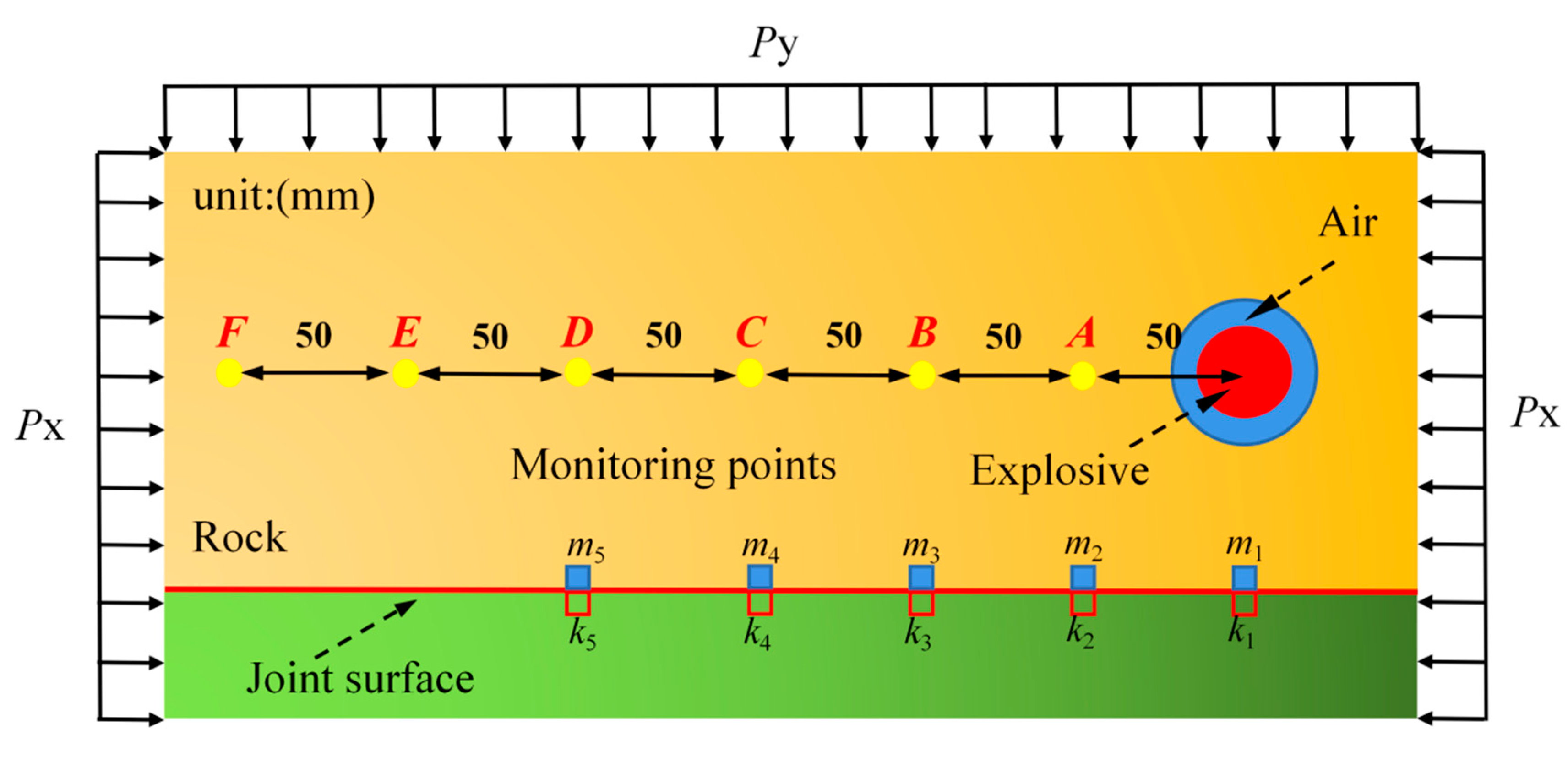
A computational model of single-hole blasting was developed using ANSYS/LS-DYNA numerical simulation software to analyze the influence of in-situ stress on rock blasting effect and the crack distribution characteristics of pressure field.
Figure 2 shows the schematic view of the hard roof blasting and the measuring point position. The initiation conditions of the model are as follows: the diameter of the boreholes are 20 mm, 30 mm, 40 mm, and 60 mm, respectively, and the surrounding rock pressure of the
X-axis and
Y-axis are 5 MPa and 15 MPa, respectively. A non-reflective boundary was set around the model, and displacement constraints were imposed in the thickness direction. The ALE algorithm is used to avoid calculation divergence and unreliable calculation results caused by excessive deformation of explosive and air units. The model size is 5000 mm×5000 mm×14 mm.
3.2. Material parameter
3.2.1. Rock material parameter
Considering the strain rate and brittle fracture of rock, and the isotropy and anisotropy of model materials, and the accuracy of results when low confining pressure loads are applied to the model boundary, and the initial damage characteristics of model materials, the
MAT_CSCM material model is finally select. Furthermore, the failure criterion of the rock element is defined to simulate the crack initiation and propagation process of rock blasting (*MAT_ADD_ERSION). The rock material parameters are shown in
Table 1.
3.2.2. Explosive material parameter
In the numerical simulation process, it is crucial to accurately describe the change course of pressure during detonation[
18]. The high-energy explosive material model (*MAT_HIGH_EXPLOSIVE_BURN) and the equation of state (*EOS_JWL) are used to simulate the whole detonation process[
19]. The JWL equation of state is a widely used empirical equation whose parameters are usually measured by cylinder tests. The EOS_JWL defines the pressure as:
where
is the pressure of the detonation products;
A,
B,
R1,
R2, and
ω are material constants (
Table 2);
V is the relative volume of the explosive; and
E is the internal energy of the explosive.
3.2.3. Air model parameter
Air is described by * MAT_NULL[
20], and EOS is described by *LINEAR POLYNOMIAL. The state equation of pressure-volume relation is expressed as follows:
where,
P is the detonation pressure of explosive;
,
,
,
,
,
and
are material constant;
is the current density and the initial density of the air.
is the Initial relative volume. The air material parameters are shown in
Table 3.
3.3. Analysis of simulation results
3.3.1. Crack propagation under different borehole diameters
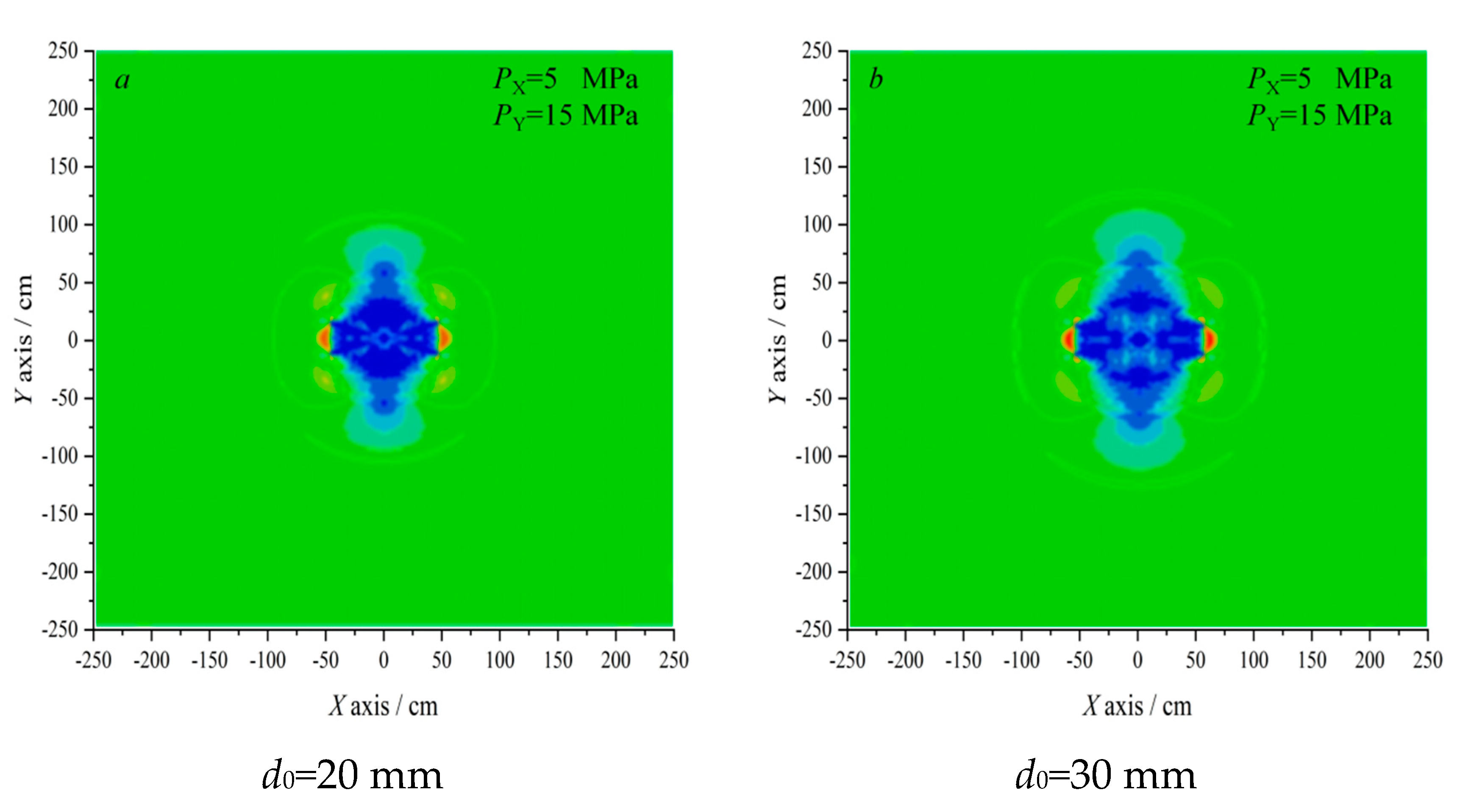
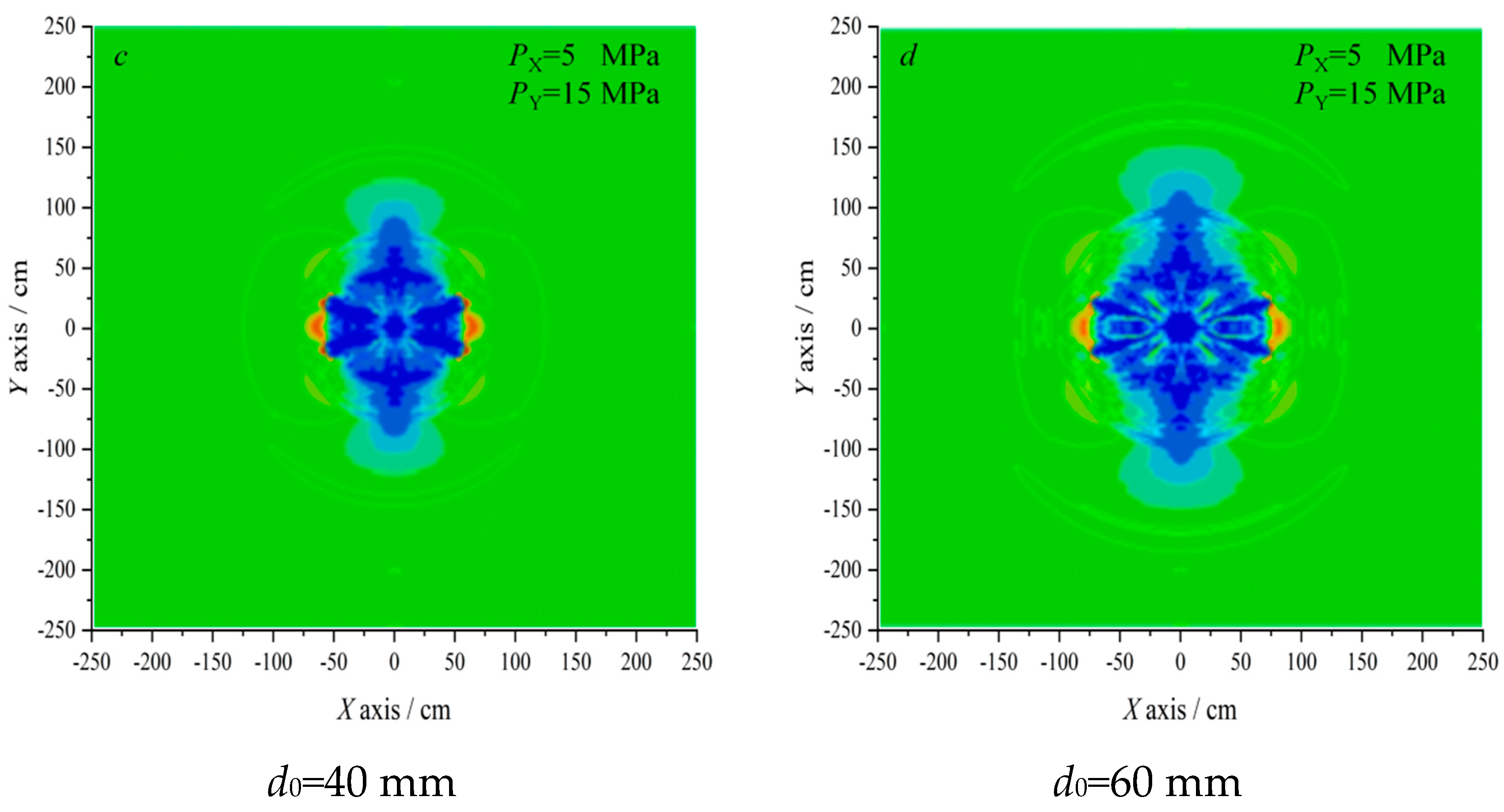
Figure 3 shows the shock wave stress nephograms under different diameters at
t=1 ms after the main explosive was detonated. The detonation energy first acts on the surrounding rock of the hole wall and then forms a high-intensity blasting dynamic load, rapidly diffusing from the hole wall to the deep surrounding rock. The detonation energy decays rapidly during the propagation. The numerical results indicated that the crack propagation is governed by the detonation energy in the vicinity of the borehole, and the confining pressure can affect the far-field crack propagation. The cracks tend to propagate towards the region of high initial pressure[
21]. Moreover, under the same in-situ stress conditions, the stress wave propagation range linearly increases with the charge diameter.
3.3.2. Failure zone analysis of rock elements
In this discussion, the model with a charge diameter of 60 mm is used as an example to analyze the variations of the equivalent stress of the rock after the main charge detonation. Six rock units are selected along the center of the borehole with an interval of 0.5 m (from monitoring point to borehole distance), as shown in
Figure 2. The monitoring data are shown in
Table 4.
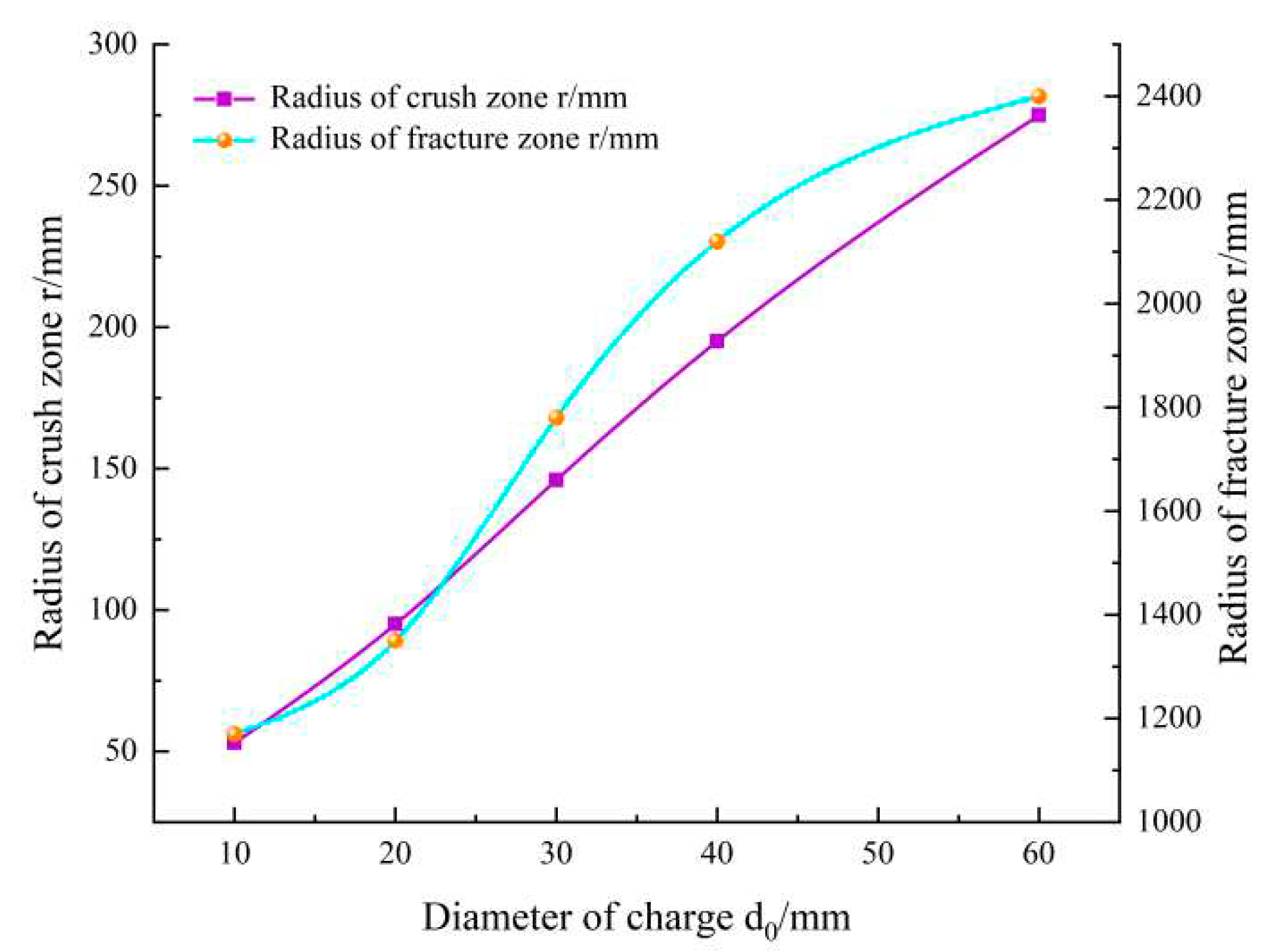
The radius range of the fracture zone and crushing area of each group of models were extracted and are in
Figure 3. The relationship curve of charge diameter is shown in
Figure 4.
Figure 4 and
Table 4 indicate that the radius of the crushing zone increases with the diameter of the charge enlargement. The radius of the crushing zone is 5 times the diameter of the charge borehole, equivalent to the cylindrical charge’s theoretical calculation value. Furthermore, the rock can be broken under the combined action of impact pressure and detonation gas, as long as the impact pressure exceeds the dynamic compressive strength. Under the premise of the same non-coupling index, the scope of the crushing zone increases with the diameter of the charge increase.
3.3.3. Reflection and Transmission of Stress Waves
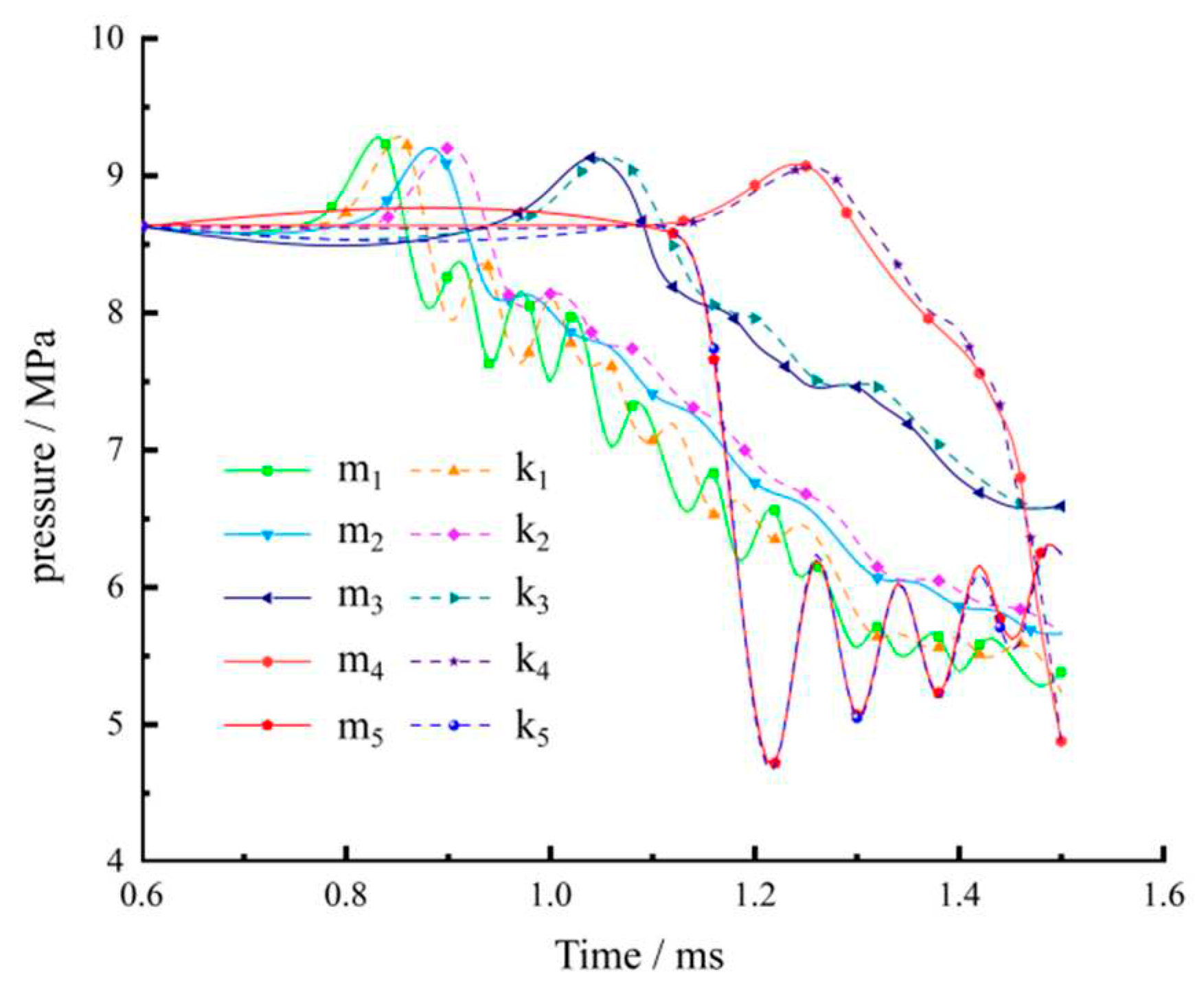
Reflection and transmission occur when stress waves encounter faults and joints in propagation. The energy consumption increases with the number of reflections. The more times the stress wave is reflected, the less efficient it is to break the rock. Six monitoring points were selected on both sides of the joint surface to analyze the pressure variation on both sides of the joint surface, as shown in
Figure 5.
Figure 5 shows that the impact pressure curve is in a state of increasing and then decreasing. The shock wave reflects multiple times at the joint, showing a sawtooth shape at the monitoring points m
1 and k
1 located directly below the charge. Extracting the incident angle of each monitoring point found that the pressure value of the unit first decreases and then oscillates when the incident angle ranges between 0~40°. However, unlike the normal incidence, the pressure value during the oscillation change does not continuously decrease. Reflection and transmission coexist, and the transmitted stress wave continues to propagate through the rock interior, which causes rock mass damage to a certain extent. Therefore, oblique incidence should be selected as far as possible at the joint surface to reduce reflection in engineering applications.
3.3.4. Hole wall pressure analysis
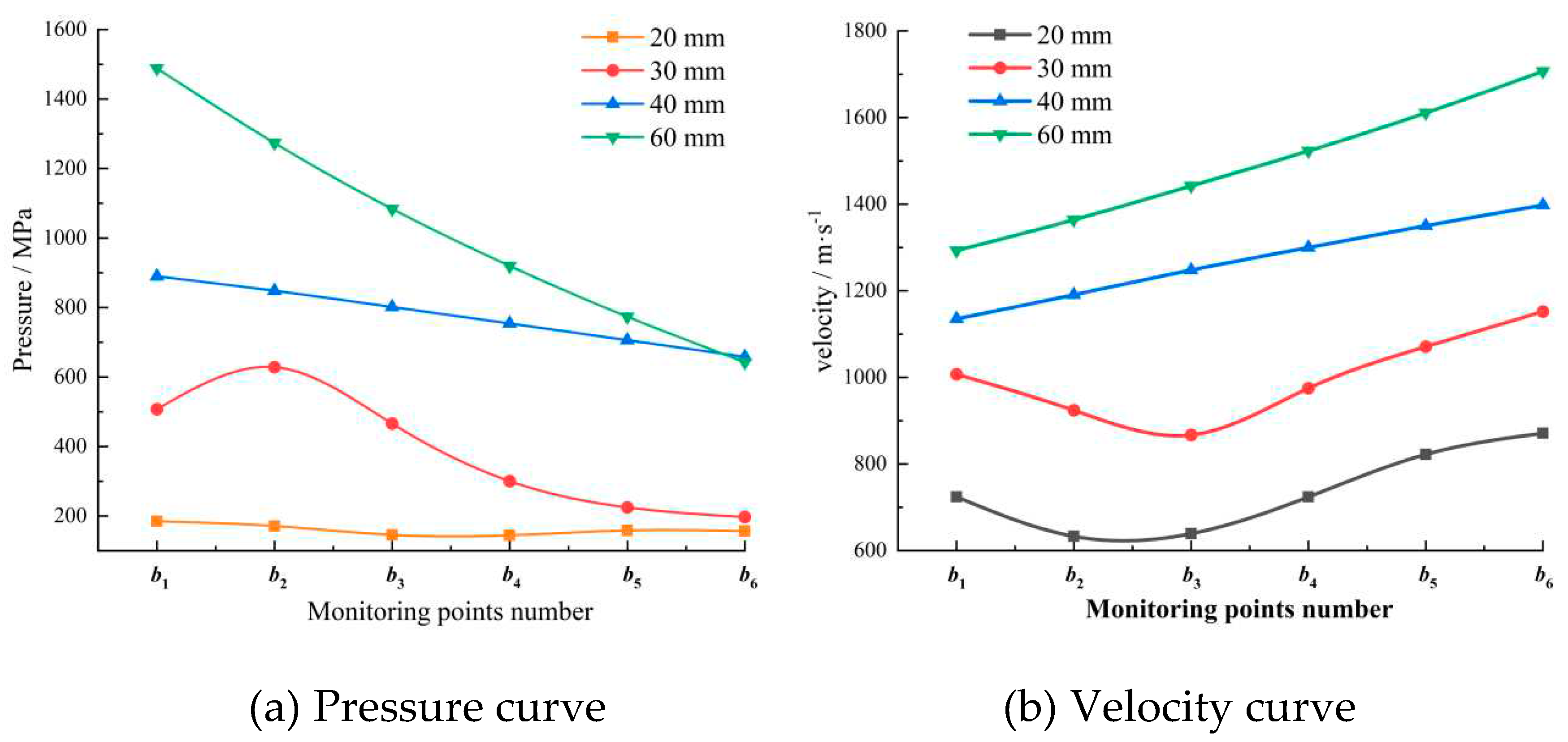
When an uncoupled charge is used, the energy generated after the explosive is detonated first acts on the air in the borehole and then contacts the rock through the air. The surrounding rock of the borehole reaches the yield failure instantaneously due to the shock wave, and the rock unit cannot directly reflect the detonation pressure. Therefore, selecting the air unit between the explosive and the rock can effectively analyze the pressure change acting on the rock after the explosive is detonated, as shown in
Figure 6. The monitoring point spacing
is the diameter of the charge.
The monitoring point data of different charge diameters were extracted to create the pressure and velocity change curves shown in
Figure 7. With propagation distance increase, the shock pressure linearly decreases. However, the impact velocity increases as the diameter of the cartridge increases, and the impact pressure and speed also increase. The maximum impact pressure of the 60 mm diameter cartridge can reach 1,488 MPa, almost 8 times that of the 20 mm cartridge. The maximum impact speed can reach 2 times that of the 20 mm diameter cartridge.
4. Engineering applications of hard roof blasting
4.1. Engineering background
The Xinhe Coal Mine is located in western Shandong Province, China. The total length of the No.6302 working face is 675 m, the inclination length is 100 m, and the burial depth of 983.9~1084 m, responding to a change in ground elevation of +35.2~+36.2 m. The comprehensive mechanized top coal mining technology was adopted for coal extraction. The west side of the working face is the 6301 working face that has been mined, with a 5 m coal pillar left in the center. The south side is the southern track, the belt collecting lane, and the bottom yard. To the east and north are the 630 mining area of the Xinhe Mining and the 630 mining area of the Tangkou Coal Industry, respectively.
4.2. Testing program
4.2.1. Blasting parameter design
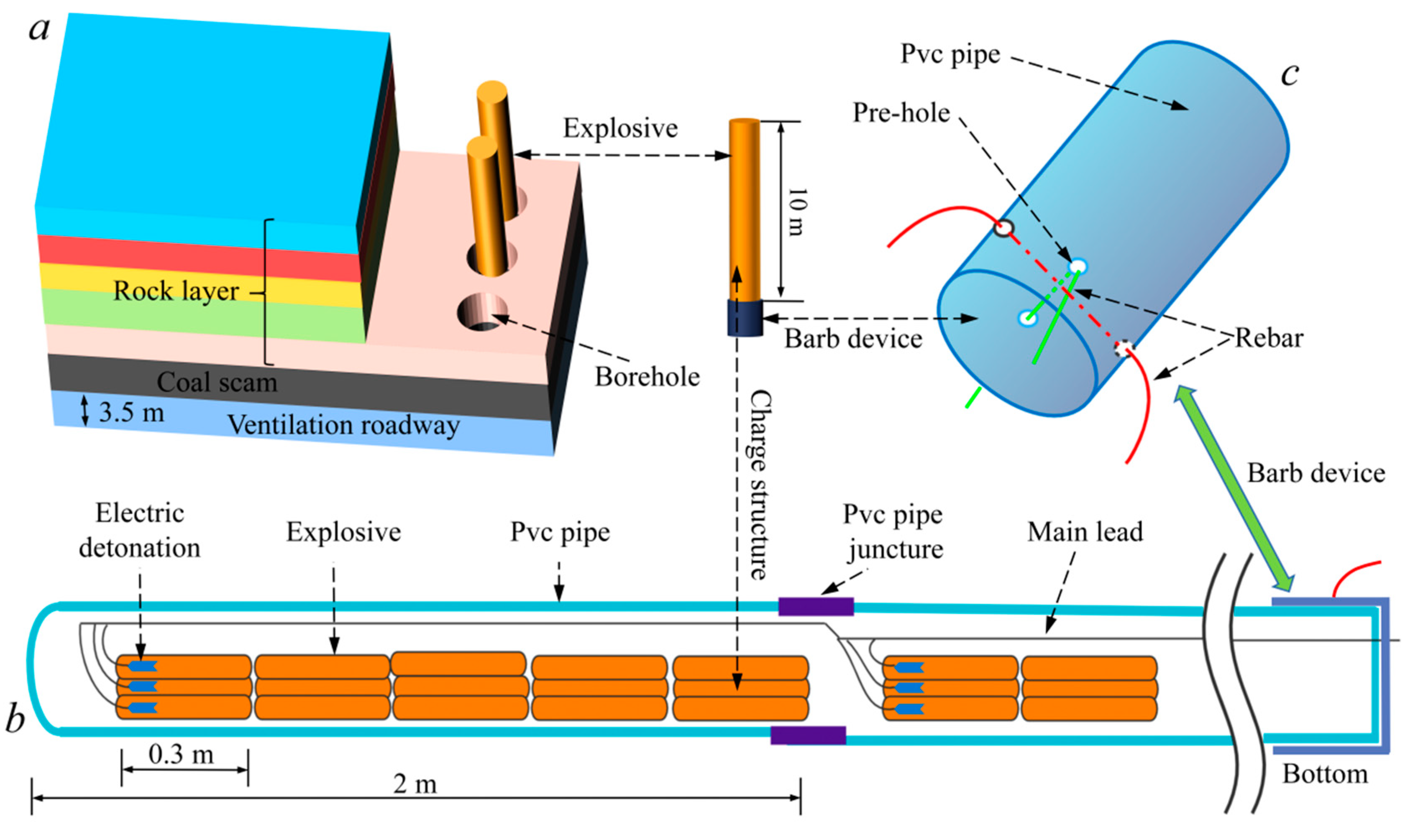
Three vertical boreholes were drilled on the roof of the intake airway of the 6302 working face for the blasting test. The borehole spacing was 10 m, and the depth was 51 m. The strata distribution and blasting parameters are shown in
Figure 8. Aqueous gels explosives permitted in secondary coal mines were used. The 5-segment millisecond delay electric detonator permitted in coal mines was used to initiate the main charge, and the delay time was 100 ms.
When the explosives and detonators arrived at the blasting site, 5 explosives were bundled with adhesive tape, and 3 electric detonators were inserted into the PVC pipe (outer diameter 75mm) by reverse initiation. The upper end of the PVC pipe was sealed with tape to prevent the leakage of explosives. A 15 cm long slit was made at one end of the PVC pipe to facilitate the connection between pipes. All the detonators were connected in parallel to the main wire, and the charge structure is shown in
Figure 8b. After the charge was completed, barbs were placed on the PVC pipe at the mouth of the borehole to prevent the explosive from falling out of the PVC pipe. The barb device is shown in
Figure 8c.
The charge length of a single borehole was 10 m, 36 kg of explosives were used, and 9 detonators were consumed. The rolls of water-gel explosives were placed in bundles in PVC pipes to form cartridges, and the cartridges were placed at the bottom of the borehole.
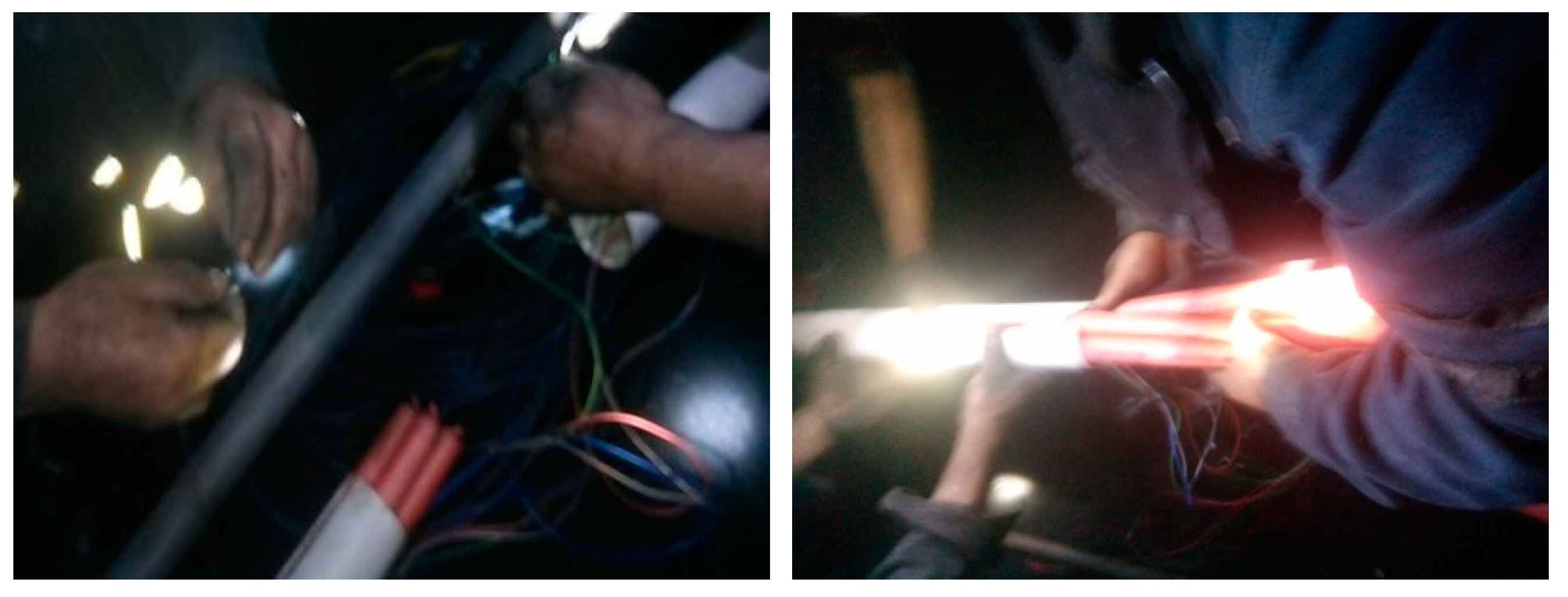
Figure 9 shows the on-site workers connecting the cartridge.
4.2.2. Parameter optimization of blasting
(1) Roof hole breakage depth and charging position
The roof hole of Xinhe 6302 working face is 51 m deep, and the deepest part has reached a key layer of siltstone with a thickness of 10.5 m. Placing explosives in this formation can effectively relieve formation pressure. After the rock formation breaks, the other rock formations it controls collapse simultaneously. The 27 m and 45 m inclination fault top holes and the bottoms reach the top of the siltstone stratum, and explosives were placed in this stratum to relieve pressure on the strata they controlled. The charge lengths were 11 m and 20 m, respectively.
(2) Uncoupling charging coefficient
As shown in the previous numerical simulation results, the range of the blasting gap is the largest when the radial uncoupling coefficient of the charge is about 1.6~1.7. The fractured top hole adopted a continuous charge in the axial direction. However, the uncoupled charge in the axial direction was used in the inclined direction because there were fractured intersections at the blasting gap.
(3) Optimize borehole spacing
The borehole spacing between adjacent boreholes was calculated from the radius of the fracture zone during single-hole blasting through the theoretical calculation formulation. Generally, the crack area is more prominent when the two holes are detonated simultaneously than during differential initiation. Furthermore, the stress wave of the two boreholes is superimposed and canceled during the propagation process. The size of the crack area was obtained through a test explosion experiment[
22]. The calculation results show that the theoretical calculated fracture radius is about 13.39% larger than the numerical simulation, and the radius of the fracture zone does not exceed 5 m. Combined with the analysis of the scope of the crushing area, the effective blasting range of the 75 mm coil is about 5 m. Therefore, the spacing between two boreholes is set at about 10 m in line with the theoretical basis.
4.3. Analysis of the test results
4.3.1. Coal Wall Stress Analysis
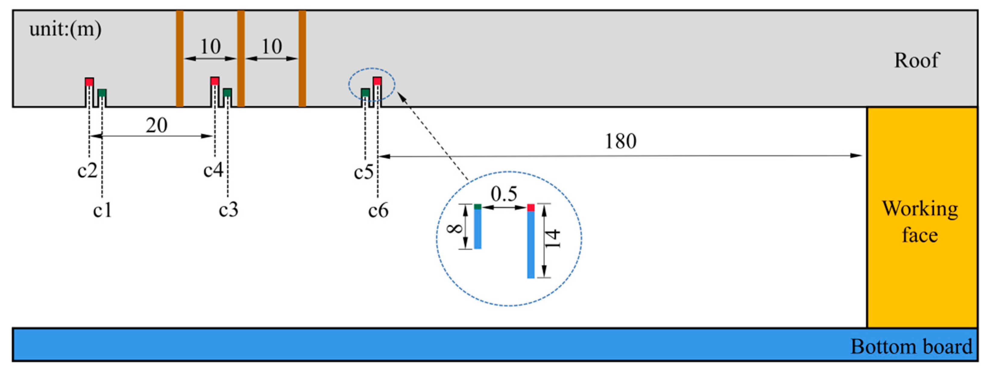
Each group of stress receivers was spaced 0.5 m apart, and the burial depths were 8 m and 14 m, respectively. The shallow hole was close to the blast hole side. The initial value of the stress measuring point installation was set to 5 MPa, and the alarm triggers when the stress in the deep hole exceeds 12 MPa or the stress in the shallow hole exceeds 10 MPa. Two sets of stress receivers, located at the deep hole and the shallow hole, were placed on the coal wall at an interval of 20 m, and 15 groups of sensors were installed on the coal wall. During the blasting test, the stress receivers corresponding to the position of the borehole were numbered c3 and c4. It was 180 m away from the working surface, and the specific layout is shown in
Figure 10.
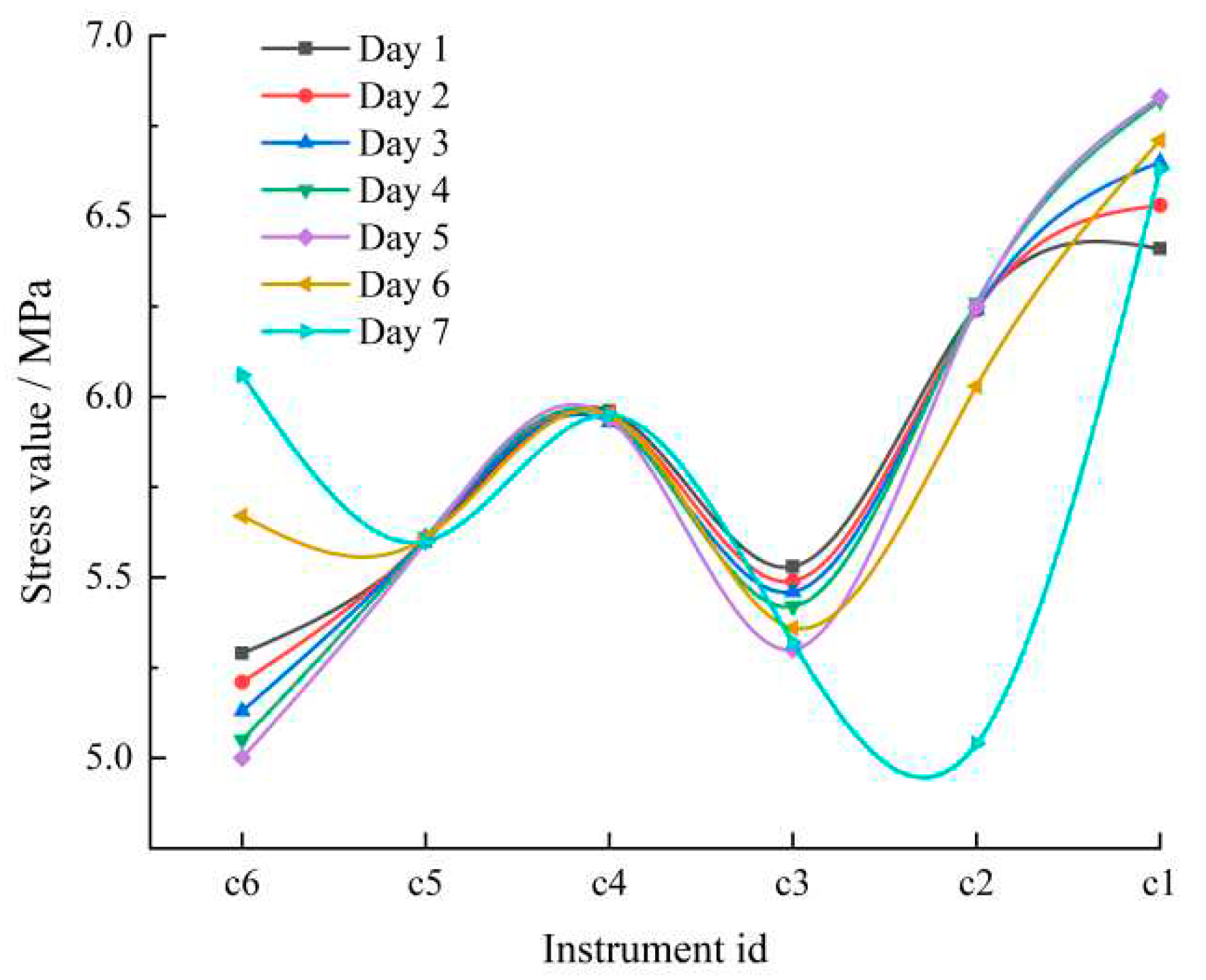
The stress receiver output a set of data every minute. Three groups of stress monitoring values were extracted to analyze the changes in coal seam pressure caused by blasting, creating the stress curve with the mean value, as shown in
Figure 11.
Overall, the closer to the working face, the greater the stress value. The stress at c3, c4, and c5 has a small variation range, but the stress at c1 and c2 significantly fluctuates. It shows that the roof rock layer is broken after blasting, and the range of the broken zone is about 20 m, close to the distance between the two sets of stress gauges. The radius of the crack zone of single-hole blasting is about 5 m. The roof pressure is released to the depth of the coal seam and the working face, which can achieve a better pressure relief effect.
4.3.2. Analysis of Microseismic Monitoring
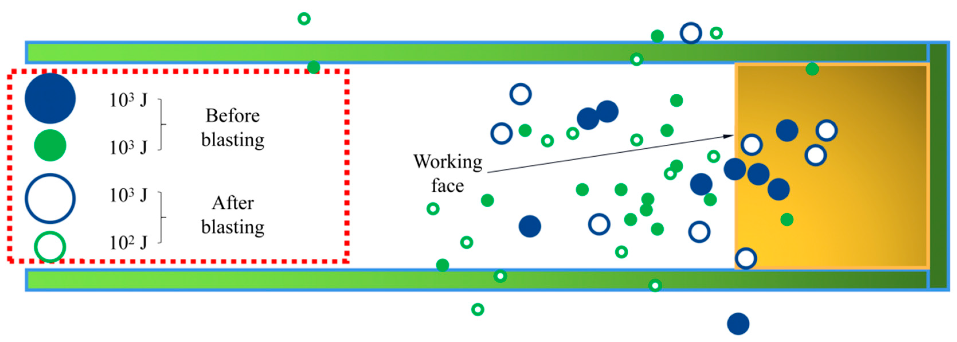
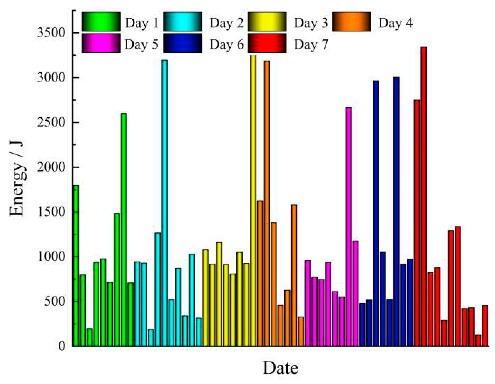
Figure 12 shows the microseismic events of three days before and after blasting. According to the monitoring data, there were 25 microseismic energy events greater than 10
2 J before blasting and 24 microseismic energy events greater than 10
2 J after blasting. In the three days before and after blasting, 10
3 J-level incidents occurred 9 times, each near the working face. The large-energy events are transferred to the tunnel face after the broken roof occurs, and the stress distribution is no longer concentrated. Overall, the rock formation in front of the working face is broken after blasting, which can release elastic energy accumulation and reduce the probability of rockbursts.
Figure 13 shows the change law of energy events three days before and after blasting. 10
2~10
3 J level energy events accounted for 56.25%, and 10
3~10
4 J level energy events accounted for 43.75%, both of which did not reach the orange warning level. The operating range was within the safety threshold. From
Figure 13, the rock layer does not break immediately after blasting and still has partial bearing capacity. After a period of time, large deformation and breakage occur and then tend to stabilize.
5. Conclusions
Numerical simulations were conducted to analyze the damaged area of different diameter charges to study the influence of in-situ stress on the blasting damage area. Field tests were conducted on the 6302 working face in the Xinhe Coal Mine. The main conclusions are as follows:
(1)The explosion load mainly affects the damage zone near the borehole, while the in-situ stress mainly affects far-field crack propagation. The crack propagates in the direction of high surrounding rock pressure. The shock wave adopts the oblique incidence method at the joint surface, effectively reducing the reflection frequency and achieving the optimal rock-breaking effect.
(2)The shock and stress waves generated by the detonation of different diameter charges determine the crushing area size. The explosion gas determines the fracture zone secondary expansion and extension length. When the non-coupling coefficient is 1.5, the impact pressure of the 60 mm diameter borehole is 8 times that of the 20 mm, and the impact speed can reach 2 times that of the 20 mm.
After optimization of the blasting parameters in the Xinhe coal mine, the radius of the single-hole blasting crack zone is about 5 m. The high energy of the roof is transferred to the front of the working face, the distribution is no longer concentrated, and a better effect of blasting pressure relief is achieved. Overall, the research results have a specific guiding significance for underground engineering in deep projects.
Declaration of competing interest
The authors declare that they have no known competing financial interests or personal relationships that could have appeared to influence the work reported in this paper.
Acknowledgments
The study was supported by the Natural Science Foundation of Shandong Province of China (No. ZR2019BA023), Natural Science Foundation of China (Nos. 51879135, 52064004), and the Foundation of Hubei Key Laboratory of Blasting Engineering (No. BL2021-06). The authors wish to express their thanks to all of their sponsors.
References
- Liu, Z.; Cao, A.; Zhu, G.; et al. Numerical Simulation and Engineering Practice for Optimal Parameters of Deep-Hole Blasting in Sidewalls of Roadway[J]. Arabian Journal for Science and Engineering 2017, 42, 3809–3818. [Google Scholar] [CrossRef]
- Konicek, P.; Waclawik, P. Stress changes and seismicity monitoring of hard coal longwall mining in high rockburst risk areas[J]. Tunnelling and Underground Space Technology 2018, 81, 237–251. [Google Scholar] [CrossRef]
- Ahmed, S.S.; Gunzburger, Y.; Renaud, V. Initialization of highly heterogeneous virgin stress fields within the numerical modeling of large-scale mines[J]. International Journal of Rock Mechanics and Mining Sciences 2017, 99, 50–62. [Google Scholar] [CrossRef]
- Liu, K.; Li, Q.; Wu, C. Optimization of spherical cartridge blasting mode in one-step raise excavation using pre-split blasting[J]. International Journal of Rock Mechanics and Mining Sciences 2020, 126. [Google Scholar] [CrossRef]
- Yang, X.; Wang, C.; Chu, H. Study on the Stress Field and Crack Propagation of Coal Mass Induced by High-Pressure Air Blasting[J]. Minerals 2022, 12. [Google Scholar] [CrossRef]
- Tu, M.; Zhao, G.; Zhang, X. Fracture Evolution between Blasting Roof Cutting Holes in a Mining Stress Environment[J]. Minerals 2022, 12. [Google Scholar] [CrossRef]
- Ge, J.; Xu, Y. Test and mechanism analysis for crack propagation by blasting in rock under the condition of unidirectional load[J]. Journal of Vibroengineering 2022. [CrossRef]
- Lv, Y.; Yuan, C.; Fu, Y. Empty-hole effect on fracture propagation under blasting load[J]. Arabian Journal of Geosciences 2022, 15. [Google Scholar] [CrossRef]
- Liu, Z.; Cao, A.; Liu, G. Experimental Research on Stress Relief of High-Stress Coal Based on Noncoupling Blasting[J]. Arabian Journal for Science and Engineering 2018, 43, 3717–3724. [Google Scholar] [CrossRef]
- Chen, B.; Liu, C.; Wu, F. A deep-hole microblasting technique for controlling coal wall spalling during mining of a vertically jointed seam[J]. Energy Science & Engineering 2022. [Google Scholar]
- Pan, J.; Du, T.; Gao, J. Mechanism and Prevention of Rockburst in Deep Multipillar Gob-Side Entry[J]. Lithosphere 2022, 2021. [Google Scholar] [CrossRef]
- Zhang, G.; Li, Y.; Meng, X. Distribution Law of In Situ Stress and Its Engineering Application in Rock Burst Control in Juye Mining Area[J]. Energies 2022, 15. [Google Scholar] [CrossRef]
- Luo, Y.; Xu, K.; Huang, J. Impact analysis of pressure-relief blasting on roadway stability in a deep mining area under high stress[J]. Tunnelling and Underground Space Technology 2021, 110. [Google Scholar] [CrossRef]
- Chen, Z.; Xu, T.; Dai, X. Effect of Borehole Positions and Depth on Pressure Relief of Cavern Surrounding Rock Mass[J]. Geotechnical and Geological Engineering 2021, 40, 237–248. [Google Scholar] [CrossRef]
- Onederra, I.A.; Furtney, J.K.; Sellers, E. Modelling blast induced damage from a fully coupled explosive charge[J]. Int J Rock Mech Min Sci (1997) 2013, 58, 73–84. [Google Scholar] [CrossRef]
- Wang, Z.; Ma, Z.; Xia, Y. Testing Method for the Range of Fracture Zone of Rock Slope under Blasting Load[J]. Shock and Vibration 2021, 2021, 1–12. [Google Scholar] [CrossRef]
- Lou, X.; Zhou, P.; Yu, J. et al. Analysis on the impact pressure on blast hole wall with radial air-decked charge based on shock tube theory[J]. Soil Dynamics and Earthquake Engineering 2020, 128. [Google Scholar] [CrossRef]
- Wang, Z.; Wang, H.; Wang, J. Finite element analyses of constitutive models performance in the simulation of blast-induced rock cracks[J]. Computers and Geotechnics 2021, 135. [Google Scholar] [CrossRef]
- Miao, Y.; Li, X.; Kong, L. Study on the symmetric bilinear initiating technique of deep-hole boulder blasting in the TBM tunnel excavation[J]. Tunnelling and Underground Space Technology 2021, 111. [Google Scholar] [CrossRef]
- Chen, T.; Wang, H.B.; Wang, L.M. Numerical analysis of decoupling coefficient influence on rock breaking effect of underwater blasting[J]. Engineering Blasting 2022, 28, 25–32. [Google Scholar]
- Yi, C.; Johansson, D.; Greberg, J. Effects of in-situ stresses on the fracturing of rock by blasting[J]. Computers and Geotechnics 2018, 104, 321–330. [Google Scholar] [CrossRef]
- Li, X.; Pan, C.; Li, X. Application of a synthetic rock mass approach to the simulation of blasting-induced crack propagation and coalescence in deep fractured rock[J]. Geomechanics and Geophysics for Geo-Energy and Geo-Resources 2022, 8. [Google Scholar] [CrossRef]
|
Disclaimer/Publisher’s Note: The statements, opinions and data contained in all publications are solely those of the individual author(s) and contributor(s) and not of MDPI and/or the editor(s). MDPI and/or the editor(s) disclaim responsibility for any injury to people or property resulting from any ideas, methods, instructions or products referred to in the content. |
© 2023 by the authors. Licensee MDPI, Basel, Switzerland. This article is an open access article distributed under the terms and conditions of the Creative Commons Attribution (CC BY) license (http://creativecommons.org/licenses/by/4.0/).
