Submitted:
09 July 2023
Posted:
11 July 2023
You are already at the latest version
Abstract
Currently, the design of the concrete mix is an important part of the environmental problem. In front of this question, engineers face a major challenge that is addressed in two ways. On one hand, how do they use its component materials to improve its mechanical properties, on the other hand how do they use less polluting materials?
Hence, in an environmental and economical view, laboratory tests were carried out on samples of concrete reinforced with smooth steel fiber extracted from the waste tires, in order to assess its impact and to prove its mechanical feasibility for these purposes.
Consequently, laboratory results have shown satisfactory improvement in the behavior of concrete under compression loads in the elastic stage and an increase in ductility and toughness of the matrix in the plastic stage.
Besides, taking into account the discontinuity and the structural disturbances observed during the loading of samples in the post-elastic state, a method has been proposed to calculate "the effective toughness and toughness Index of fiber concrete; on the other hand, this method has helped to better optimize length and slenderness of fibers for better use of this recycled material
Keywords:
smooth steel fibers
; waste tires
; compression strength
; effective toughness index
Interest Statement
The reinforcement of concrete with steel fibers is in fact a return to an ancient technique where man invested the biomaterials of his environment to meet his construction needs. Historically, in the Middle East not so long ago, people added wheat straw to mud bricks to build their houses and hemp fibers to plaster.
Thus, based on the environmental and economic interest, this research had the vision to work on the valuation of the use of steel fibers extracted from worn tires to invest this waste profitably.
Introduction
The gain of using steel fibers, produced from recycling waste tires, in concrete batches is its wide field of applications; moreover, in environmental and economic point of view, this option is justified by the large amounts of tires left as negligible in nature. The “Tire industry project for the world business council for sustainable development (2022)”, claims that one billion end-of-life tires are generated every year. The report estimates that there are currently 4 billion such tires in landfills and stockpiles worldwide; Likewise, the report Assessment of markets for fiber and steel produced from recycling waste tires, established in 2003 by the State of California, estimates that steel fiber in the tire composition can reach 15% of its weight.
For decades and still today, the use of steel fiber has been the subject of many researches in order to justify the benefit of its use in the manufacture of concrete. Thus, Graeff (2011) looked at the long-term performance of steel fiber concrete. She proved that the fibers are a good quality manufactured product that can be reused to improve the mechanical properties of the plain concrete, which leads to the reduction of the pavement depth; hence, she considered that the design codes for road pavements do not take into account the post-cracking behavior of Steel fiber concrete (SFRC) and the fatigue criteria. Likewise, Tlemat et al. (2006), Aiello et al. (2009), have previously justified this choice for factories ground slab to reduce damages resulting from wear and impacts, for machinery foundations to minimize damage caused by vibrations and dynamic loads, for roads and airstrips to reduce slab crack. Moreover, Johnston (1996) studied the role of SFRC in reducing the damaging airstrips due to the extreme loads acting on the pavement. Aslani and Jowkarmeimandi (2012) proposed a Stress–strain model for concrete under cyclic loading.
The ACI (5441.R-96) describes the suitable characteristics of steel fibers for concrete batches. Despite the positive properties of this material, the random and inhomogeneous distribution of fibers act negatively on consistency and workability of concrete (Kooiman, 2000). In order to remedy these defects, Hannant (1978) looked on the slenderness role on flow and workability. Thus, Johnson (1996) advised that the nominal size of concrete should not exceed half the fiber length, to prevent fiber clumping. In another way. Chan et al. (1997) recommended the use of plasticizers to improve workability. Naaman (2003) describes the characteristics of fibers that give greater effectiveness of fiber concrete. Achilleos Et al. (2011) worked on proportioning the steel fiber reinforced concrete for pavement. Bazgir, 2016 treated the effect of the volume ratio of fibers in concrete batch.
Furthermore, Kearsley, E.P. et al. (2003) looked at the effect of ductility on load-carrying capacity of steel fiber concrete for ground slabs. Oikonomou-Mpegetis (2012) studied the behavior of steel fiber concrete slabs under static loads, whilst Trevor et al. (2014) treated the effect of impact loads.
In 1952 Cox introduced his original theory of the stress transfer from the paper matrix to the fiber which could be used in the same way for fiber concrete. Li and Stang (2001), Laranjera (2010) have been proposed probabilistic parameter to take into account the random distribution of fibers in concrete batch. In the same way, Löfgren (2005) developed this parameter for different forms of distribution.
The investment of the steel fiber extracted from waste tires was at the choice of this research to show its feasibility to improve the concrete properties under compression loads.
Materials and Laboratory Tests
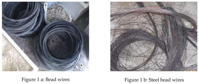
Steel Fibers
Smooth steel wires were extracted from beads of worn tires by splitting them from rubber (Figure 1 a and b). To clean fibers from the rubber residue, they were placed in an anaerobic oven at 180 C° for enough time until residues turned into soot of coal. After cooling, the wires were cut into 3, 4, 6 cm lengths and placed in Los Angeles Abrasion test drum with a quantity of natural dune sand to mechanically clean them of the residual soot.
Fibers had a diameter of 0.8 mm; thus, to determine their mechanical viability, a sample of 5 wires was subjected to standard tensile test. The results give a yield strength of 1875±114 MPa. Therefore, this value is in agreement with ASTM A A820-96that recommends a tensile strength greater than 345 MPa.
Concrete Batching
According to ACI 318 and ACI 544.3R-93, concrete batches were prepared for 300, 350, 400 kg/m3 of cement type II (42.5). The maximum aggregate size was 19 mm. Hence, for the three amount of cement, plain concrete was prepared as a control batch; besides, smooth steel fibers were added to concrete for volume ratio fv=0.5%, 1%, 1.5% (equivalent to 39.25, 78.5, 117 kg/m3). Table 1 gives data concerning steel fibers used in the concrete tests.
In accordance with ACI 318 recommendation, cubic samples of 15 cm were prepared for all concrete batch after adjusting consistency. The samples were cured and conserved in water of 24±1 C°, and then tested at age of 28 days.
Concrete Consistency
For trial concrete mix design, it was necessary to take into account three factors, the length and the volume ratio of the steel fibers which could affect the workability and increase the percentage of voids, on the other hand the need to acquire a compression strength compatible with the yield strength of the steel fibers.
Taking these factors into account and to ensure a similar consistency for all batches (with and without fibers), a chemical additive type G (Water-reducing, high range, and retarding admixtures) was added with an appropriate quantity which varied from 1.2 to 2.4 kg per 100 kg of cement as needed. Hence, the slump varied between 10 and 12 cm, depending on volume ratio and length of the fibers.
Results and Discussion
Compression Tests
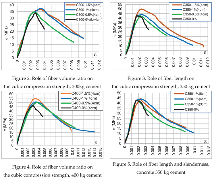
To reveal the effect of steel fiber on the concrete compression strength, tests were carried out gradually where the first ones were on concrete of 300, 350 and 400 kg / m3, with fibers of 4 cm length and a volume ratio of (0.5, 1 and 1.5%). The second step was for concrete of 350 kg cement with fibers of 3, 4, 6 cm length for 1% volume ratio. The results of compression test are shown in Figure 2, Figure 3, Figure 4 and Figure 5.
Besides, the compression test shows two types of rupture, where plain concrete takes the form of pyramid, while the samples of fiber concrete have maintained their cubic shape (Figure 6).
Benefits of Using Steel Fiber
Effectively, as shown by curves (ε-σ) the first benefit of adding steel fiber is the wide ductility that concrete can gain. Figure 2, Figure 3, Figure 4 and Figure 5 show that the rupture of fiber concrete occurs at large strain and goes from a value of ε=0.3-0.4% for plain concrete to ε=1.2-1.4% for fiber concrete.
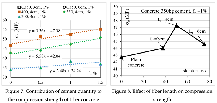
Role of Cement Quantity
As stated previously, regardless of the amount of cement, the improvement in concrete’s strength depends on the fiber volume ratio while the fiber length plays a modest role.
Figure 7 shows that the relation between fiber concrete strength and fiber volume ratio could be described by a simple linear relation of the form:
where, (σo) is strength of plain concrete, (a) constant related to cement quantity, (fv) fiber volume ratio.
σ = σo + a.fv
Meanwhile, the regression lines for 300 kg cement shows slow efficiently contrary to the cases of 350 and 400 kg cement where the concrete’s strength has a significant improvement; this result could be explained by the weak strength of concrete,
Role of Fiber Length and Fiber Slenderness
Figure 8 gives an idea how fiber length and slenderness act on the compression strength for a given amount of cement, where the slenderness of 4 cm fiber length is more distinguished compared to that of 3 and 6 cm Figure 8.
Apparently, the fiber for 3 cm length slowly improves the concrete’s strength; while the fiber for 6 cm length decreases significantly the strength acquired by the fiber for 4 cm length. These results lead to a conclusion that long fibers, exceeding 2 time the concrete nominal size, can cause a structural disturbance of fresh concrete and consequently affect and decrease the compression strength of hardened concrete.
Effect of Number of Fibers
Taking into account the state of discontinuity and the structural disturbances that the concrete samples have undergone in the post-elastic state, the analysis of the effect of number and size of fibers on the strength of fiber was carried out for resistances limited to the deformation of 0.2% corresponding classically to the elasticity yield stress.
The line of regression shown in Figure 9 prove that, for a given fiber length, the increase of fv value (from 0.5% to 1.5%, for a length of 4 cm) improves the strength of fiber concrete.
Contrary to the previous result, the regression lines in Figure 10 show that, for a given fiber volume ratio, the increase of the fiber’s number by the decrease of their size decreases partially the strength of the material. This is probably due to the random distribution of the fibers and the creation of voids where the fibers interlock.
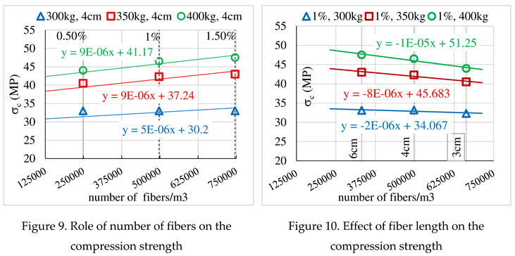
Therefore, the concrete mix design must make a compromise between the length and the number of fibers. Thus, it seems that for a concrete of nominal dimension 19 mm, the most suitable is the volume ratio of 1% for a length of 4 cm.
Toughness and Toughness Index Criterion
Following meticulously the process of the compression test, the physical state of the fiber concrete sample on the plastic deformation stage becomes discontinue and disturbed, which partly explains the randomness of the rupture strain of the fiber concrete sample, showed in Figure 2, Figure 3, Figure 4, Figure 5 and Figure 6.
Given this physical state of the material, any structural element loses eventually part of its mechanical properties and function. Therefore, it is difficult to define the correct failure stage, contrary to the plain concrete, which collapses in brittle behavior form. Meanwhile, the force-deformation that the device continues to provide seems to dissipate not on the strength of the continuous material, but on the cohesion and the bond between the concrete fragments and the steel fibers, as well as on bending and shearing deformation of the fibers.
Hence, it appears that the calculation of the toughness of fiber concrete should be considered for deformations that does not exceed the physical stability of the sample. In accepting this concept, it is logical to take for comparative reference the failure load of the plain concrete to calculate the toughness (T) of fiber concrete and the toughness index TI.
The ductility of the fiber concrete, expressed quantitatively by the toughness criterion, is formulated by the general function T=f(C, fv, Lf/df), where C the quantity of cement, fv, the fiber volume ratio, Lf/df the fiber slenderness. Furthermore, the value of Toughness (T) is calculated by the surface area under force-displacement:
Thus, the volume toughness for 1 cubic meter of concrete will take the form
According to the previous concept, the proposed toughness value called effective toughness is calculated by integration of the surface area under the curve (σ-ε) between two limits, the deformation of the elastic yield stress (defined conventionally at ε=0.2%) and the plastic deformation corresponding to load rupture of the plain concrete (Figure 11)
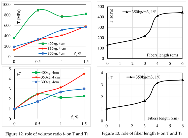
The value of the effective Toughness Tv and Toughness Index TI are given in Table 2 (for 1 cube of 15 cm), for the fiber concrete of 300, 350 and 400 kg/m3 cement and 4 cm fiber length. Also, Table 3 gives the value of the effective Toughness Tv and toughness Index TI for the fiber concrete of 350 kg/m3 cement with various fiber lengths and 1% fiber volume ratio. Meanwhile, the values of ε% given in the Table 2 and Table 3 are for the ductile strain corresponding to the considered failure load (f) of the plain concrete as shown in Figure 11.
Figure 12 presents the value of Tv and TI and shows that for concrete of 400kg cement, the role of steel fiber is limited from fv=0.5%, and its increase does not improve significantly the toughness of fiber concrete; otherwise, the different values of fv contribute and significantly improve the mechanical properties of fiber concrete for 350kg cement.
The same remark is noted for fiber concrete of low amount of cement (300kg), but this improvement may be due to the moderate resistance of plain concrete. The curve of 300 kg cement shows a certain tendency to be limited after a value of fv =1.5%. These results allow concluding that the effect of the fiber volume ratio is related to the characteristic properties of plain concrete.
Figure 13 shows the value of the effective toughness and the toughness index of fiber concrete for 350kg cement and fv=1%. The curves show that the significant effect of fiber is limited to the fiber length of 4 cm; thus, this confirms the previous conclusion where the best fiber length is ruled by the nominal size of the concrete aggregate. Hence, for maximum aggregate size of 19 mm fibers could be limited to 4cm length and 1% volume ratio.
Fiber Contribution to Concrete Strength
Admitting the random distribution of fibers in the concrete mix, Li and Stang (2001) propose a fiber orientation factor (ηφ) in the volume space (Figure 14). Its value is calculated by integration of the probability formula of the density function of 2 parameters p(z), p(Φ), where (z) the center of gravity of fibers and (Φ) its orientation in the space. So, (ηφ) take the form (ηφ3D) and has the value ηφ3D =1/2
On the base of logic of correlation between continuous and discontinuous medium (Biarez et al. 1989), (Favre et al. 1993), the fiber concrete obeys in the elastic state to Hook’ Law σ = ε.E, and the compression load applied on the fiber concrete is expressed as follows:
where Ft, Ff, Fc are respectively the portion of applied force on the total section, the portion force on the fibers, the portion force on the concrete. Hence, this equality is developed as follows:
where Am, Af, and Ac are respectively the total cross-section area of the sample, the equivalent cross-section area of the fibers, and the cross-section area of the concrete.
σm, σf, and σc are respectively the maximum compression stress on section area, the compression stress portion of fibers, the compression stress portion of the concrete.
Figure 17 shows that the contribution of the stress force on steel fibers depends of the concrete properties, the steel’s Volume ratio as well as on the fiber’s length. However, the fiber’s contribution gradually decreases with increasing its volume ratio regardless of the amount of cement. Similarly, the length of the fiber loses its role from a certain length, here 4 cm in length.
This conclusion is consistent and matches well with what was presented previously.
Conclusion
To calculate the feasibility of introducing the smooth steel fiber in concrete batch, this study proposes a modified concept to calculate the effective toughness, which takes into account the random failure, the structural disturbance, and the performance of the fiber concrete after the elastic stage.
From a rheological point of view, the steel fiber extracted from waste wires has the feasibility to improve the concrete strength under compression loads in elastic stage. Although, the effect of the waste steel fiber on the compression strength is modest, it has the ability and the performance to increase significantly the ductility and the toughness of the concrete in the plastic stage.
Finally, the length, the slenderness, and the volume ratio condition the feasibility and the performance of the steel fiber in the matrix of concrete.
Acknowledge
This article is in memory of our colleague Rim AL-Hafez who passed away shortly after defending her thesis, and with our deep appreciation for her work, we wish her peace
References
- ASTM A820-96. Standard Specification for Steel Fibers for Fiber-Reinforced Concrete.
- ACI Committee 544.4R-88, Design Considerations for Steel Fiber Reinforced Concrete.
- ACI 318-14. The “Building Code Requirements for Structural Concrete” (“Code”) provides minimum requirements for the materials.
- Graeff, A.G. 2011. Long-term performance of recycled steel fiber reinforced concrete for pavement applications. PhD. Thesis, University of Sheffield.
- Tlemat, H., Pilakoutas, K., Neocleous, K. (2006) Stress-strain characteristic of SFRC using recycled fibers, Materials and Structures. https://doi.org/10.1617/s11527-005-9009-4. [CrossRef]
- Aiello M. A., Leuzzi F. 2010. “Waste tires rubberized concrete: Properties at fresh and hardened state”, Waste Management, 30, 1696-1704. [CrossRef]
- Johnson, C., 1996. Flexural fatigue behaviour of SFRC, influence of fiber content, fiber type and aspect ratio. ACI Materials Journal, pp. 155-179.
- Aslani, A., and Jowkarmeimandi, R., 2012. Stress–strain model for concrete under cyclic loading. Magazine of Concrete Research. https://doi.org/10.1680/macr.11.00120. [CrossRef]
- Kooiman, A.G. 2000. Modelling Steel Fiber Reinforced Concrete for Structural Design, Delft: Technische Universiteit Delft.
- Hannant D.J., 1978. Fiber Cements and Fiber Concrete, Wiley, Chichester.
- Chan, Y.W. and Li, V.C. 1997. Effects of Transition Zone Densification On Fiber/Cement Paste Bond Strength Improvement, Advanced Cement Based Materials. https://doi.org/10.1016/S1065-7355(97)90010-9. [CrossRef]
- Naaman, A., 2003. Engineered Steel Fibers with Optimal Properties for Reinforcement of Cement Composites. Journal of Advance Concrete Technology. https://doi.org/10.3151/JACT.1.241. [CrossRef]
- Achilleos C., Hadjimitsis, D., Neocleous, K., Pilakoutas, K., Pavlos O. Neophytou, K.P. and Kallis, S. 2011. Proportioning of Steel Fiber Reinforced Concrete Mixes for Pavement Construction and Their Impact on Environment and Cost. Sustainability. https://doi.org/10.3390/su3070965. [CrossRef]
- Bazgir, A. 2016. The Behaviour of Steel Fiber Reinforced Concrete Material and its Effect on Impact Resistance of Slabs. City London University.
- Kearsley, E.P. and Elsaigh, W., (2003). Effect of ductility on load-carrying capacity of steel fiber reinforced concrete ground slabs. Journal of the South African Institution of Civil Engineering, 45(1).
- Oikonomou-Mpegetis S., 2012. Behaviour and design of steel fiber reinforced concrete slabs. PhD thesis, Imperial College London,.
- Trevor D. Hrynyk and Frank J. Vecchio, 2014. Behavior of Steel Fiber-Reinforced Concrete Slabs under Impact Load. ACI Structural Journal 111(5):1213. https://doi.org/10.14359/51686923. [CrossRef]
- Cox, H.L. 1952. The elasticity and strength of paper and other fibrous materials. British journal of applied physics, Volume 3, pp. 72-79. https://doi.org/10.1088/0508-3443/3/3/302. [CrossRef]
- Li, V.C. and Stang, H. (2001): Meso: Averaging, In Mechanics of Fibre Reinforced Cement Based Composites, International Graduate Research School in Applied Mechanics, course material, Lyngby, Denmark 2001.
- Laranjeira de Oliveira, F., 2010. Design orientated constitutive model for steel fiber reinforced concrete. Universitat Politècnica de Catalunya.
- Löfgren, I., 2005. Fiber-reinforced Concrete for Industrial Construction - a fracture mechanics approach to material testing and structural analysis, Göteborg, Sweden: Chalmers University of Technology.
- Biarez, J., Favre, J.L., Hicher, P.Y. Rahma, A. 1989. Correlations for granular media, classification logic and connections between classes. International conference on micromechanics of granular media.
- Favre, J.L., Rahma, A., (1993). Classification logic and correlation between soils parameters: Application to an elastoplastic law. Probamat Workshop 1993, Cachan, France.
Figure 6.
Form of sample failure, (a) plain concrete, (b) fiber concrete.
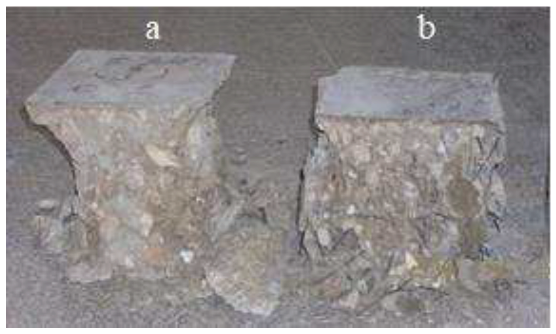
Figure 11.
The proposal method to calculate the Toughness T and Toughness Index TI=TB/TA.
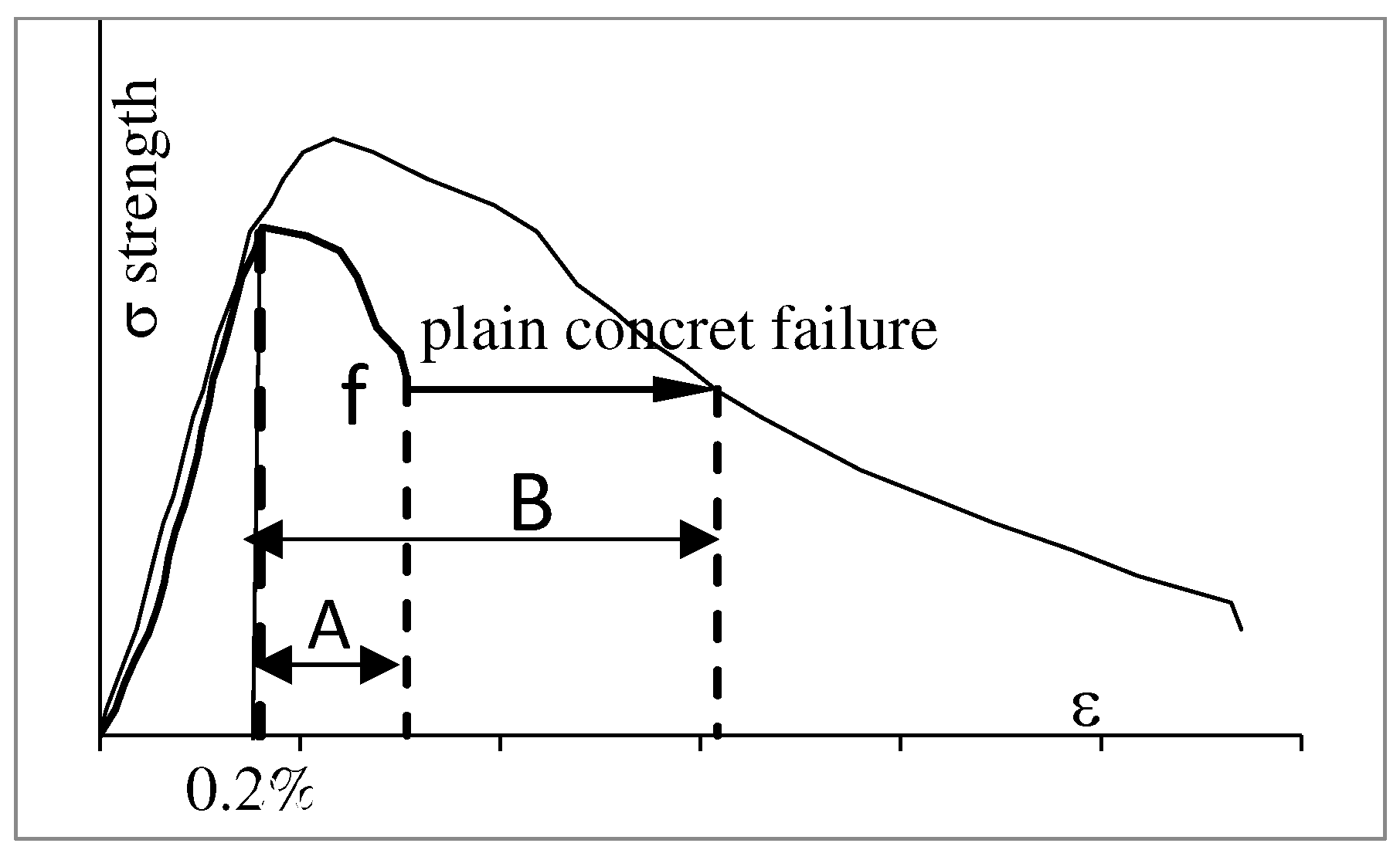
Figure 14.
Random distribution of fiber orientation in 3-D (from Li and Stang 2001).
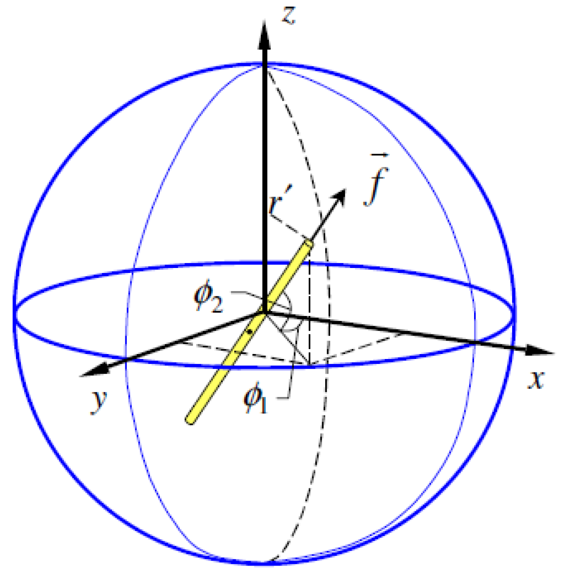
Figure 17.
contribution of fibers to the compression strength of concrete. (a) Rule of volume fiber ratio, (b) Rule of fiber length.
Figure 17.
contribution of fibers to the compression strength of concrete. (a) Rule of volume fiber ratio, (b) Rule of fiber length.
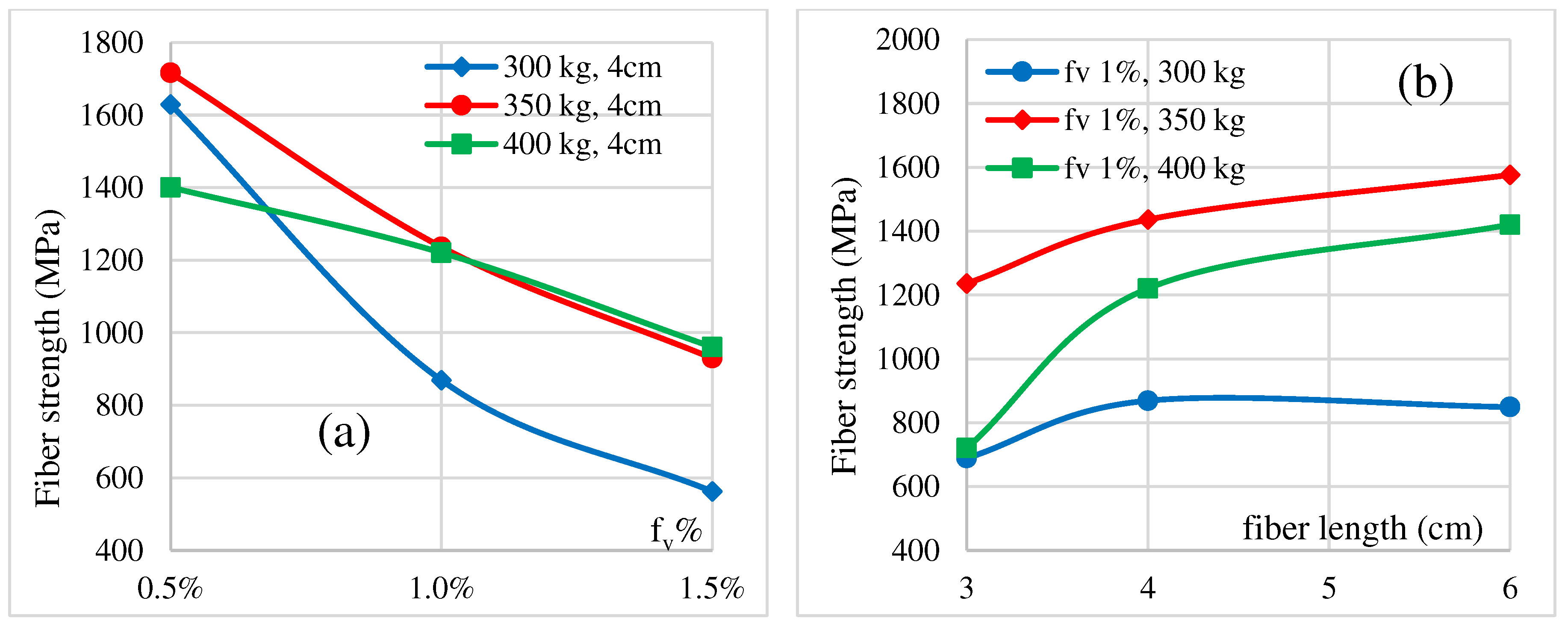

Table 1.
Characteristics data of the smooth waste steel fibers.
| Diameter Df (mm) | Length Lf (cm) | SlendernessDf / Lf | volume ratio fv % | ||
| 0.5 | 1 | 1.5 | |||
| Weight of fibers (kg) per 1 m3 concrete | |||||
| 39.25 | 78.5 | 117.75 | |||
| Numbers of fibers per 1 m3 concrete | |||||
| 0.8 | 3 | 37.5 | 331573 | 663146 | 994718 |
| 0.8 | 4 | 50 | 248680 | 497359 | 746039 |
| 0.8 | 6 | 75 | 165786 | 331573 | 497359 |
Table 2.
Toughness Index (T) for 300, 350, 400 kg/m3 and different fibers ratio.
| Cement weight, (fiber length) | fv | 0 | 0.5% | 1% | 1.5% |
|---|---|---|---|---|---|
| 300kg, (4cm) | Tv (MPa) | 190 | 330 | 510 | 570 |
| TI | 1.00 | 1.74 | 2.68 | 3 | |
| ε% | 0.40 | 0.54 | 0.70 | 0.78 | |
| 350kg, (4 cm) | Tv (Mpa) | 130 | 320 | 410 | 585 |
| TI | 1.00 | 2.46 | 3.15 | 4.54 | |
| ε% | 0.33 | 0.47 | 0.53 | 0.64 | |
| 400kg, (4cm) | Tv (Mpa) | 360 | 890 | 770 | 820 |
| TI | 1.00 | 2.47 | 2.14 | 2.28 | |
| ε% | 0.47 | 0.72 | 0.70 | 0.71 |
Table 3.
Toughness and Toughness Index for 350kg cement and different fiber’s length.
| Length of Fiber | 0 | 3 cm | 4 cm | 6 cm |
| Tv (Mpa) | 130 | 220 | 410 | 445 |
| TI | 1 | 1.7 | 3.15 | 3.40 |
| ε% | 0.33% | 0.45% | 0.53% | 0.57% |
Disclaimer/Publisher’s Note: The statements, opinions and data contained in all publications are solely those of the individual author(s) and contributor(s) and not of MDPI and/or the editor(s). MDPI and/or the editor(s) disclaim responsibility for any injury to people or property resulting from any ideas, methods, instructions or products referred to in the content. |
© 2023 by the authors. Licensee MDPI, Basel, Switzerland. This article is an open access article distributed under the terms and conditions of the Creative Commons Attribution (CC BY) license (http://creativecommons.org/licenses/by/4.0/).
Copyright: This open access article is published under a Creative Commons CC BY 4.0 license, which permit the free download, distribution, and reuse, provided that the author and preprint are cited in any reuse.


