
Submitted:
05 July 2023
Posted:
07 July 2023
You are already at the latest version
Abstract
In response to the problem of no supporting equipment for the cultivation of Codonopsis in the hilly and mountainous areas of northwest China, a combined machine for transplanting outcrop of Codonopsis with micro ridge covered with film is designed. The key components of the prototype are analyzed and designed, and the structures and working parameters of the seedbed preparation device, seedling casting device, rotary tillage soil-covering device, film covering device, seedling head burial and film edge soil-covering device are determined. The transmission system scheme is established, and the working mechanism of the core components is analyzed. Field experiments show that when the target seedling spacing is 4.4cm and the machines moves forward at the speed of 0.1, 0.15, and 0.2m/s, the variation coefficient of planting spacing and the qualification rate of planting depth all meet the standard requirements. The qualified rate of planting posture and film side outcrop are greatly affected by the operating speed of the machine, and decrease with the increase of operating speed. When the operating speed reaches 0.1m/s, the average variation coefficient of planting spacing is 0.08%, the average qualified rate of planting depth, planting posture and film side outcrop is 95.83%, 94.17% and 93.33% respectively, which shows that the operating performance is better than that of the operating speed of 0.15m/s and 0.2m/s. This study provides new reference for the theoretical research and design of mechanized and automated transplanting machinery for Codonopsis seedlings.
Keywords:
mechanization
; design
; film side outcrop cultivation
; Codonopsis
1. Introduction
Gansu Province is located at the intersection of the Loess Plateau, the Qinghai-Tibet Plateau and the Inner Mongolia Plateau. Its complex and diverse landforms, ecological and climatic conditions, and multi-ethnic settlement history have bred rich resources of Chinese medicinal materials. Among them, the output and market share of Codonopsis both account for more than 90% of the country[1], so Codonopsis has become an important source of farmers’ income in the region. In order to reduce moisture retention and increase soil temperature, Codonopsis planting in this area adopts the film-covered outcrop transplanting technology[2,3]. At present, it is basically finished with manual operation without supporting equipment.
According to the falling posture of seedlings, transplanting mode can be divided into vertical planting, horizontal planting and oblique planting. In order to meet the planting mode and agronomic requirements of different plants, researchers have made many innovations and researches on transplanting machines. The self-propelled pepper transplanter designed by Md Zafar Iqbal et al. [4] has reduced the breakage rate of plastic film caused by working parts and improved the upright degree of seedling transplanting by analyzing and designing the working speed of the gear driven direct insert mechanism. Luhua Han et al. [5] proposed a self-propelled fully automatic rice transplanter, which combined mechanical, electrical and pneumatic technologies to realize the automatic feeding and transplanting process of vegetable seedlings, greatly improving the planting efficiency. Xin Jin et al. [6] designed a vegetable single row transplanting device using mechatronics technology based on tomatoes, which can meet the high-speed transplanting requirements of vegetable seedlings. The above models are mainly used for vertical transplanting of vegetables and other crops. Other scholars carried out horizontal mechanized transplanting of some crops. Wei Yan et al. [7] designed a horizontal sweet potato transplanting machine to achieve horizontal transplanting of naked sweet potato seedlings, which saved labor and improved planting quality. In view of the oblique transplanting mode of naked seedlings, Xu Gaowei et al. [8]developed the oblique transplanting device on salvia miltiorrhiza film, Wu Guangwei et al. [9]developed the automatic transplanting machine of naked seedlings with sweet potato based on pre-treatment seedlings, and Wang Xujian et al. [10]developed the liquorice oblique transplanting ditch cutter. Mulching is essential in the process of pot seedling transplanting in dryland, the compound operation machine designed by Mingjun et al. [11]integrates hole, in-hole fertilization, transplanting, water injection and soil covering in the hole and mulching, which meets the requirements of mulching and drought resistance, but the film needs to be broken and seedlings be released in the later stage of planting. Dejiang Liu et al. [12] designed a dryland cantaloupe transplanting machine, which realized the precise formation of soil in the seeding hole and solved the problem of transplanting dryland cantaloupe. The whole machine adopted the method of mulching before breaking the film, which reduced the continuous insulation performance of the mulching film. In summary, the existing transplanting machine cannot meet the agronomic requirements of transplanting naked seedlings of Codonopsis while the labor intensity of manual transplanting and the planting cost is high.
In this paper, according to the agronomic requirements of Codonopsis transplanting, a combined machine for transplanting outcrop of Codonopsis with micro ridge covered with film is designed, and the field experiments are tested in order to provide a new reference for the theoretical research and innovative design of mechanization and automatic transplanting machinery of Codonopsis.
2. Structure and working principle of the machine
2.1. Agronomic requirements
Figure 1 is a schematic diagram of the cultivation mode of Codonopsis outcrop on micro ridge covered with plastic film. The height of ridge is 60~80mm, the row spacing is 700mm and 300mm, the film side outcrop width is 0~40mm, the oblique planting angle of the seedlings is 15°, and the plant spacing is 44mm. Two bundles of black mulch with a width of 620mm and a thickness of 0.01mm are selected to cover the two ridges with a width of 700mm.
2.2. Operation Procedure
The manual transplanting procedures of Codonopsis seedlings are shown in Table 1, which mainly include seedbed preparation, seedling placement, seedling soil-covering, film mulching, film edge and seedling head soil-covering.
2.3. Structure and main technical parameters of the machine
As shown in Figure 2, the combined machine for transplanting outcrop of Codonopsis with micro ridge covered with film is mainly composed of frame, hanging device, seedbed preparation device, power transmission device, seedling casting device, rotary tillage soil-covering device, seedling head burial and film edge soil-covering device, etc. The seedbed preparation device, seeding device and rotary tillage soil-covering device are the main working parts, and the rationality of the design and configuration of these devices directly affects the operating performance of the whole machine. The main technical parameters of the machine are shown in Table 2.
2.4. Working principle
This machine can complete the ditching and ridging, seedbed preparation, seedling casting, seedling covering, film mulching, film edge and seedling head covering and other operations at one time. Before the operation, the seedlings are placed on the seeding device manually. The head of the seedlings should be aligned with the high position of the seedbed when placed. During operation, the whole machine is connected with the three-point suspension frame of the tractor through the suspension device. Under the pull of the tractor, the ditch shovel completes the work of ditching and ridging, then, the seedbed preparation device completes the ridge direction scraping, the extrusion of the seedling covering belt and the forming of seedbed along with the progress of the whole machine. The earth wheel transmits the power to the seedling casting device through the chain drive, and then the seedling casting device completes the transmission and casting of the seedlings. The tractor will pass the power through the gearbox to the rotary tillage soil-covering device which will cut the soil in high speed and the cut soil is thrown to both sides of the seedbed to cover the seedlings. The film installed on the film hanging frame can be uniformly coated with the aid of the film spreading roller. Finally, the covering disk would cover the film edge with soil and backfill the ridge. The seedling casting device can ensure the plant spacing is not affected by the advance speed of the whole machine by making the ground wheel drive the chain so that the seedling spacing is stable.
3. Design of main working parts
3.1. Seedbed preparation device
Seedbed preparation device is one of the core working parts of the combined machine for transplanting outcrop of Codonopsis with micro ridge covered with film. The design and spatial location of the shaper directly affect the quality of seedbed preparation and subsequent seedling casting, thus affecting the overall outcrop effect of Codonopsis seedlings after mulching. Therefore, according to its agronomic requirements, this paper has conducted the relevant analysis and calculation of the shaper to achieve the function of the seedbed preparation. At the same time, the soil-covering belt of seedlings is formed, which ensures the amount of soil thrown by rotary tillage. A seedbed preparation device is specifically designed, which is connected with the frame. The seedbed preparation device is composed of two shapers, each has a crushing roller and the distance between the two shapers is 200mm.
3.1.1. Structure and operation principle
As shown in Figure 3, the seedbed preparation device is mainly composed of shaper, crushing roller, crushing roller regulating rod, connecting rod of shaper, adjusting rod of shaper, etc. The structure size and spatial position of shaper directly affect the molding of ridge bed and the quality of collected soil in ridge and furrow. The shaper is made of 65Mn steel plate with a thickness of 10mm. The working surface is designed into a right angle trapezoid structure. The angle between the hypotenuse and the long right angle is 75°, which can ensure that the included angle between the seedlings and the horizontal plane is 15°. In order to ensure that the soil will not exceed the top of the shaper when scraping, the width of the shaper is set to be 330mm, and the length of the short side is 200mm. The shaper is welded on the connecting rod of the shaper. In order to meet the requirements of different ground conditions, the operator can adjust the shaper up and down through the adjusting rod of the shaper and the adjusting bolt. The crushing roller is installed on the shaper through the adjusting rod of the crushing roller, and its axis is parallel to the bevel of the shaper. The height of the crushing roller can be adjusted through the crushing roller adjusting rod and adjusting nut. The upper and lower height adjustment of the shaper and the crushing roller and the adjustment of the ground wheel of the operation machine jointly determine the depth of the shaper into the soil and the position of the crushing roller. The adjustable range of the shaper and the crushing roller is 0~150mm and 0~250mm respectively.
Figure 4 shows the operation process of seedbed preparation device. In the process of seedbed preparation, while the shaper and crushing roller move forward, the crushing roller would crush the soil and suppress soil moisture. The seedbed and seedlings soil-covering belt are formed after the soil is turned through the shaper. When the crushing roller contacts with the soil on the seedbed, it would roll and crush the soil to overcome the friction force and cohesion between seedbed and soil particles, compress the gravity water, attached water and the space between soil particles in the soil layer, and discharge the air in the soil layer[13] so as to ensure the soil particles are closely arranged and the seedbed is flat, thus avoiding the instability of plant spacing, the overall deviation of the seedlings and poor outcrop.
3.1.2. Theoretical aggregate amount of soil
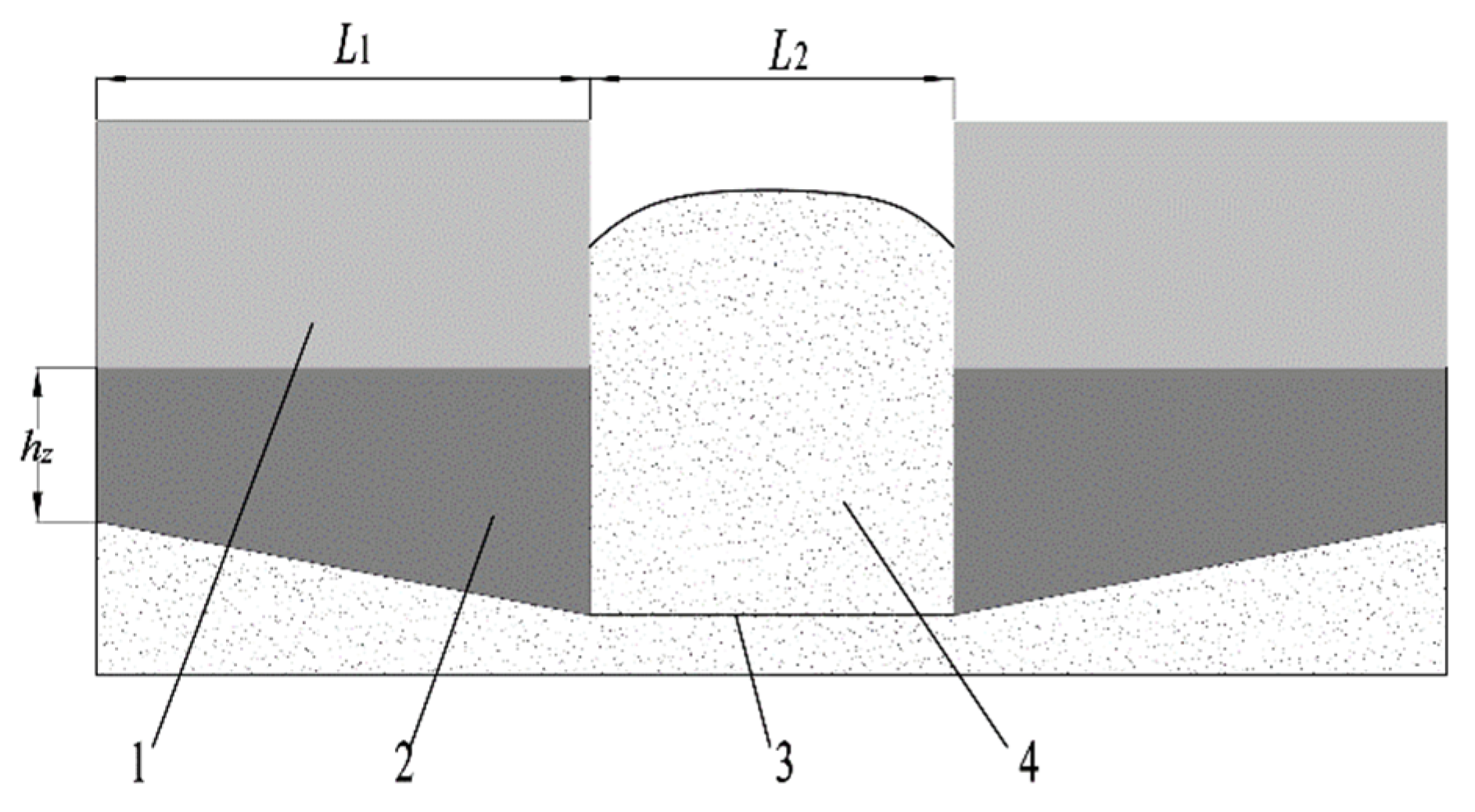
As shown in Figure 5, while moving forward, the shaper needs to push soil in front, transport the soil to the lateral side and extrude the soil so as to form the soil- covering belt of seedlings. In order to make sure the amount of soil collected on the soil-covering belt of seedlings and the thickness of the covering soil on the seedlings in the subsequent rotating tillage process, the amount of soil collected by the shaper needs to be calculated theoretically. The area of soil collection is calculated through the effective cross-sectional area of the shaper multiplies a certain length, and then the advance distance of the whole machine equals to the amount of collected soil Y
Where:
Where Y is the advancing distance of the whole machine which is 1m
is the bulk weight of soil (yellow soil) (1300kg/m) [32].
S1 is the cross-section area (m2)
hz is the depth of the short side of the shaper into the soil (0.07m)
L1 is the cross-sectional length of the shaper (0.25m)
L2 is the distance between the two shapers (0.2m)
It can be calculated from Formula (1) that 69.2kg
When the advance distance of the whole machine is Y, the amount of covering soil required by the seedlings
Where:
Where, the thickness of covering soil required by seedlings H is 0.07m.
It can be calculated from Formula (2) that 37.6kg
Because ˃, the soil collection operation of shaper meets the theoretical requirement.
Figure 5.
Schematic diagram of operation process of the effective cross-section of the shaper. 1. Bulldozing surface 2 Scraper plane 3. The action line of the rotary blade tip 4 The soil-covering belt of seedlings.
Figure 5.
Schematic diagram of operation process of the effective cross-section of the shaper. 1. Bulldozing surface 2 Scraper plane 3. The action line of the rotary blade tip 4 The soil-covering belt of seedlings.
3.1.3. Mechanical analysis of shaper
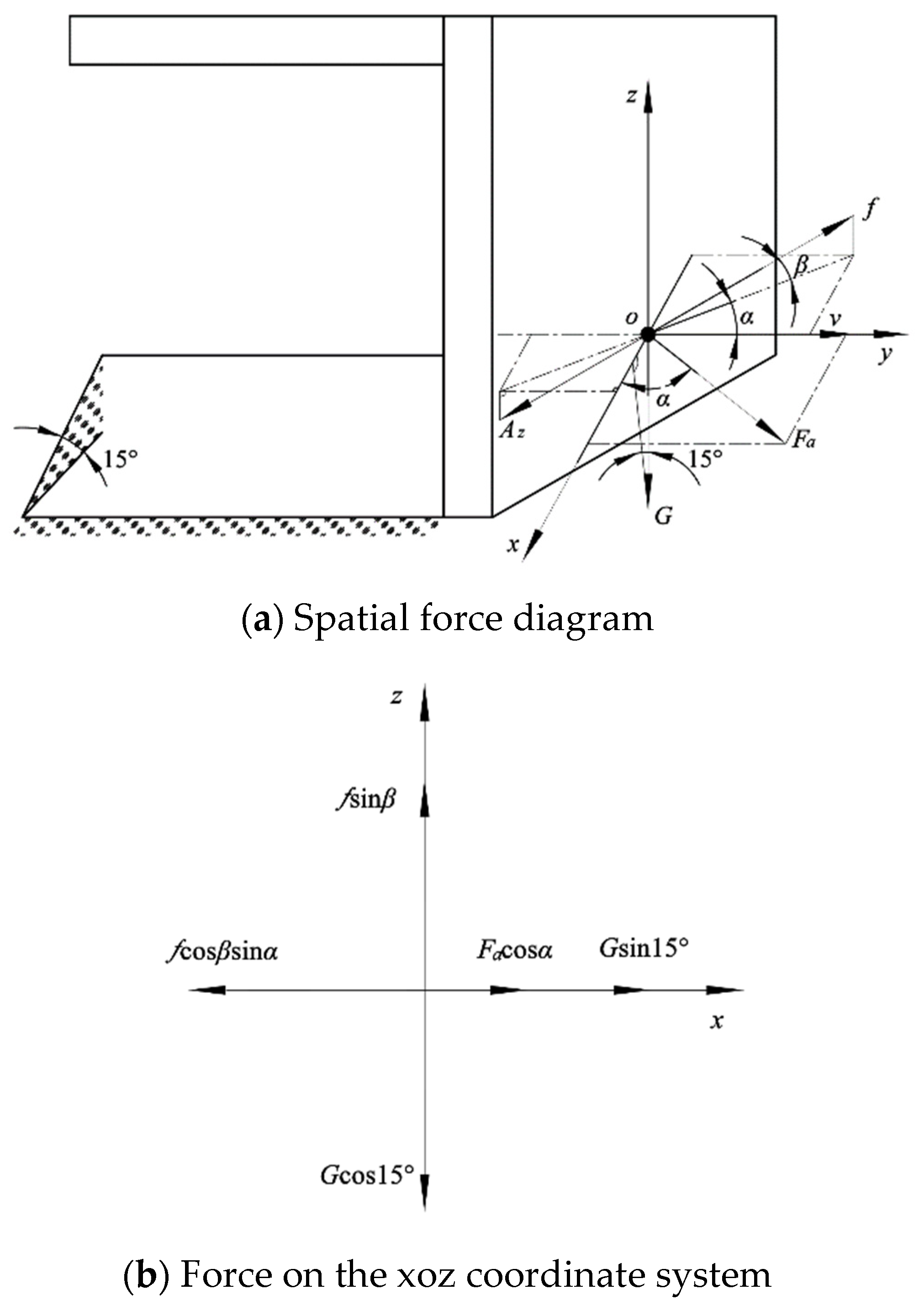
In order to study the operation rule of the shaper for collecting soil in ridge and analyze the main influencing factors on the quality of collected soil in ridge, it is found that the quality of collected soil in ridge is not only related to the structural parameters and soil parameters of the shaper, but also to the installation angle of the shaper. Suppose the angle between the working surface of the shaper and the moving direction of the machine is α (that is, the installation angle α), then the larger the installation angle α, the larger the operation width, the greater the resistance of the scraper, which is prone to cause the soil be piled up[14,15,16]. If the installation angle α is too small, it can not meet the required width of seedbed, that is, the installation angle α should be reduced when the width of seedbed is met. In order to determine the mechanical conditions of soil scraping along ridges and furrows, it is assumed that there is no relative force between soil particles at the moment of sliding. There is no relative displacement between the soil particles and the working face of the shaper. Figure 6a shows the spatial mechanical analysis of the moment of slip of a single soil particle. Taking the soil particle center as the origin O, the direction parallel to the seedbed as x, the forward direction of the operating machine as y, and the direction perpendicular to the seedbed as z, the space rectangular coordinate system is established. Setting the direction of motion of a single particle at the moment of slip be Az, it is seen that the operation surface slip of the shaper is reciprocated by the combined effects of normal force Fa, friction f and gravity G. Decomposing the above forces into the xOz coordinate system, as shown in Figure 6b, the resultant force Fx of the soil particle along the X-axis is
Where, the angle β is the included angle of Az projection on the surface (°).
Taking the formula of friction f into formula(3)
Where:
μ is the friction coefficient between soil particle and operating surface of shaper
G is gravity (N)
In formula (4), the friction coefficient μ between the soil particle and the operating surface of the shaper can be measured. The included angle β is related to the motion direction Az at the moment of slip, The installation angle α can be determined by artificial adjustment, Soil particles will generally move in the positive direction of the x axis, and the mechanical condition is Fx>0.
Figure 6.
Spatial force analysis at the moment of soil particle slipping under the action of shaper.
Figure 6.
Spatial force analysis at the moment of soil particle slipping under the action of shaper.
According to the requirements of agronomy, the shaper should not cause soil to be piled-up greatly during its operation. When the curved form of the scraper is determined, the installation angle α is the key factor for the formation of the seedbed and the soil-covering belt of seedlings. Field experiments show that the width of seedbed can be guaranteed when the maximum installation angle α of ridge and furrow soil collection is 60° and the width of shaper is 330mm.
3.2. Seedling casting device
In order to ensure the alignment of the head of the seedlings when they are placed manually on the inclined plane of the seedbed, it is necessary to reasonably design the seedling casting device. Currently, the commonly used methods to control seedling spacing include pre-treatment of seedling belt method[9], hole disc seedling belt method[17] and artificial seedling feeding method[18]. Pre-treatment of seedling belt method requires a lot of preparation work and would consume much time, hole disc seedling belt method is suitable for transplanting seedlings with small plant spacing. Therefore, in order to improve the transplanting efficiency and meet the subsequent outcrop cultivation mode of membrane edge, this design adopts the way of artificial seedling feeding and mechanical auxiliary seedling casting. As shown in Figure 7, the seedling casting device consists of seedling protection plate, cylindrical pin, connecting block, fixed pin, seedling separation plate, conveyor belt, driving shaft of seedling casting device, driven shaft I and driven shaft II. They are fixed on the frame, relying on the rotation of the ground wheel to drive the driving shaft of the seeding device which rotates and drives the conveyor belt to move at the speed of Vc; Driven shaft I and driven shaft II support the conveyor belt, and cooperate with it to move; Position m, n and e are seedling protection area, seedling casting area and seedling dropping area respectively. At point e, the seedling protection plate opens due to its dead weight, seedlings can be placed manually. When seedlings are transported to point m, the seedling protection plate closes under the action of gravity to protect seedlings. When seedlings are transported to n point, the seedling protection plate opens to drop seedings. The seedling casting device flexibly uses the self-weight of the seedling protection plate to realize real-time seedling protection and precise seedling casting.
3.2.1. Analysis of seedling movement
According to the cultivation mode of Codonopsis outcrop with micro ridge covered with film, it is necessary to carry out movement analysis of seedling landing process in order to ensure small head deviation of seedlings when they are thrown into the seedbed.
Figure 8a shows the side view of seedling casting process (the influence of seedling protection plate on seedling casting process is not taken into consideration), the driving shaft of seeding device rotates at angular velocity ω, Vm is the advance speed of the whole machine. Suppose that after seeding is thrown from point O of height H1, the head of seeding falls to point P and the root falls to point Q, and the horizontal displacement of seeding is L. Taking the horizontal direction as the x axis and the vertical plane as the y axis, a rectangular coordinate system is established.
Air resistance is considered in the seedling casting process, and it is known that the resistance of air is proportional to its motion speed[19], namely
Where ƒa is the air resistance (N)
μ1 is the coefficient of air resistance
Vt is the seedling speed, m/s
Without considering the slip of the conveyor belt, the instantaneous speed of seedlings leaving the conveyor belt is equal to the speed of the conveyor belt, namely,
Vc is speed of conveyor belt, m/s
The forces of seedlings during seeding operation are shown in Figure 8b. OP is the motion path of seedlings. At the moment when the seedlings leave point O, their motion are influenced together by gravity (mg) and air resistance (ƒa).
Then the accelerated speed in all directions of the seedlings moving through the air is
Where is the accelerated speed of the seedling in the horizontal direction (m/)
is the accelerated speed of the seedling in the vertical direction(m/)
is the air resistance of the seedling in the horizontal direction (N)
is the air resistance of the seedling in the vertical direction (N)
g is gravitational acceleration, m/
The instantaneous velocity Vc of the seedling is decomposed when the seedling leaves from the conveyor belt, and the velocity of the seedling in the x and y directions is
By integrating Equation (7), the horizontal and vertical motion velocities of seedlings in the falling process can be written as Vxt, Vyt respectively
is the motion velocity of seedlings in the horizontal direction (m/s)
is the motion velocity of seedlings in the vertical direction (m/s)
is the angle between seeding direction and horizontal plane (°)
is the movement time of seedlings (s)
By integrating Equation (7) again, the displacement of seedlings in the horizontal direction x and in the vertical direction y is
Through the motion analysis of seedling casting process, it can be seen that the larger the angle between seedling-casting direction and horizontal plane, the smaller the horizontal displacement. The velocity of the conveyor belt is positively correlated with the horizontal displacement. When the speed of conveyor Vc, the forward speed of machine Vm, the height of seedling-casting H1 is determined (vertical displacement is determined), then the horizontal displacement is a fixed value.
3.2.2. Analysis of the collision process between seedlings and seedbed
According to the characteristics of the seedbed, the head of the seedling contacts with the seedbed first in the falling process. After that, the smaller the instantaneous velocity of the seedling, the smaller the deviation of the seedling. According to the law of conservation of momentum
Where M is total mass of seedlings (g)
is the instantaneous velocity of seedlings while contacting with the seedbed (m/s)
is the instantaneous velocity of seedlings after colliding with seedbed(m/s)
is the mass of single soil particle (g)
is the instantaneous velocity of a single soil particle after collision (m/s)
Equation (11) shows that the velocity of seedlings after collision is
It can be seen from the above equation that after the collision between the seedlings and the inclined plane, in order to make the instantaneous velocity of the seedlings small (the deviation of the seedlings should be small after the collision), the soil on the seedbed should not be too solid.
Through the analysis of the collision process between the seedlings and the seedbed, it can be seen that whether the seedlings can be cast successfully is related to the angle between the direction of seeding and the horizontal plane β1, and the soil firmness of the seedbed. During the test, in order to reduce the influence of air resistance on the effect of seeding, the angle between the seeding direction and the horizontal plane should be large. After comprehensive consideration, it is reasonable to set β1 to be 60°, while the seeding height H1 is low, so it can be set to be 80mm.
3.3. Rotary tillage soil-covering device
Rotary tillage knife can throw soil from lateral side[20,21], while in operation, the tractor will transfer power to the gearbox to change the speed of the power and drive rotary tillage soil-covering device work, the rotary tillage knife would break soil on the seedling soil-covering belt, ditch and throw soil on both sides of the seedbed to complete the seedling soil-covering operation. In order to ensure that soil covered on both sides of the seedbed is uniform in the process of rotary tillage, the rotary tillage knife on the cutter head adopts the external installation method, and the rotary tillage knife at both ends of the cutter head bends outwards. The rotary tillage knife arrangement is shown in Figure 9.
3.3.1. Analysis of soil-covering amount of rotary tillage knife
The rotating direction of the rotary tillage knife is the direction of soil throwing[22]. The process of the rotary tillage knife throwing soil is shown in Figure 10. The advance speed of the machine is Vm, the rotary tillage knife rotates at an angular speed , and the soil is thrown up by the rotary tillage knife to position and cover the seedlings. In order to ensure that the thickness of covering-soil on seedlings is 40~80mm, it is necessary to analyze the soil-covering amount of rotary tillage knife on seedbed. Firstly, the soil cutting area of a single rotary tillage knife in a single rotation period is analyzed[23].
In order to establish the parameter equation of the soil disturbed by rotary tillage knife, the area of soil(S) cut by a single rotary tillage knife in a certain cycle is determined at first, then the thickness of soil(T) cut by a single rotary tillage knife in a certain cycle is obtained, and finally the area of soil(V) disturbed by rotary tillage knife is obtained. A rectangular coordinate system was established as shown in Figure 11. The motion curve of the blade end of the adjacent rotary tillage knife in the same direction in a certain cycle is established. The blade pivot(O1) are taken as the center, the forward direction of the machine is the x-axis, and the vertical downward axis is the y-axis. The absolute motion of rotary tillage knife’ s end is the combination of rotation motion of blade pivot and forward motion of the machine, and the motion process of the end of rotary tillage knife meets the requirements of trochoid [24].
As shown in Figure 11, since the area enclosed by points P2, P3, and P4 is torn apart by the cutter teeth during high-speed rotation, the soil cutting area S is enclosed by points P1, P3, P4 and P5, the area of soil(S) cut by blade is enclosed by points P1, P3, P4 and P5. The soil cutting area of a single rotary tillage knife in a single rotation period is expressed as
Where:
is the Equation of motion curve of the first rotary tillage cutter end
is the Equation of motion curve of the second rotary tillage cutter end in the same period
The equation of motion curve of the first rotary tillage cutter end is
If the number of blades in the same direction is 3, then the lag soil-covering angle of the second rotary tillage knife in the same direction is, and the equation of motion curve of the second rotary tillage cutter end in the same direction is
Where is the pitch of soil cutting, and its coordinates meet
Where:
Z is the number of rotary tillage knife in the same direction,3
By synthesizing Equations (13)~(16), it can be calculated that the soil cutting area S is
From the equation, the time t1, t3, t4 and t5 of rotary tillage knife pass through P1, P3, P4 and P5 can be calculated as
Where:t is time (s)
ha is the tillage depth (mm)
R is the radius of rotary tillage knife (mm)
is the angular velocity of rotary tillage blade (rad/s)
Combined with Equations (17) and (18), the soil cutting area S can be calculated as
Where:
The area of soil cut by a single rotary tillage knife in one rotation cycle can be approximately calculated as the product of the area of soil cutting and the thickness of soil cutting T, and the formula for calculating the thickness of soil cutting T is[25]
Where L1 is the cutting length of the rotary tillage knife’s tangent edge, mm
is the Angle of tangent edge
According to Equations (19) and (21), the covering volume V of a seedbed soil-covering belt for one rotation of blade pivot is
According to Equations (18), (20) and (22), the volume of disturbed soil V is related to such parameters as ω1, R, L1, θ, ha, Z and Vm. When the parameters of rotary tillage knife are determined, R, L1 and θ are fixed values, so the soil-covering amount of seedbed is mainly affected by the depth of tillage ha, rotary angular velocity ω1, numbers of rotary tillage knife Z, forward speed of machine Vm. When the forward speed of machine Vm is certain, the rotation angular speed and tillage depth are the main factors affecting the soil-covering thickness. Therefore, the adjustment of the depth of rotary tillage is taken into consideration in the design of the component.
3.3.2. Analysis of axial soil-transporting performance of rotary tillage knife
In order to ensure the axial covering range of soil while rotary tillage knife tilling soil, it is necessary to determine the mechanical conditions of soil axial movement. The force of rotary tillage is mainly determined by the structural parameters and soil parameters of rotary tillage. Suppose that there is no relative displacement of soil particles on the rotary tillage knife and there is no interaction between the soil particles. Figure 12 shows the spatial mechanical analysis of a single soil particle at the moment of separation. Taking the center line of the blade axis as the origin, the direction of the center line of the blade axis as, the direction of the machine as and the direction of the vertical horizontal plane as Z1, the origin of the coordinate system O1 is translated along the plane to the center of the soil particle to obtain the spatial coordinate system. Suppose the instantaneous motion direction of the soil particle when it breaks away from the tangent plane of the rotary tillage blade be, it can be concluded that the moment it breaks away from the tangent plane of the rotary tillage knife, it is affected by the comprehensive action of normal force, friction force f1, gravity G1 and centrifugal force.
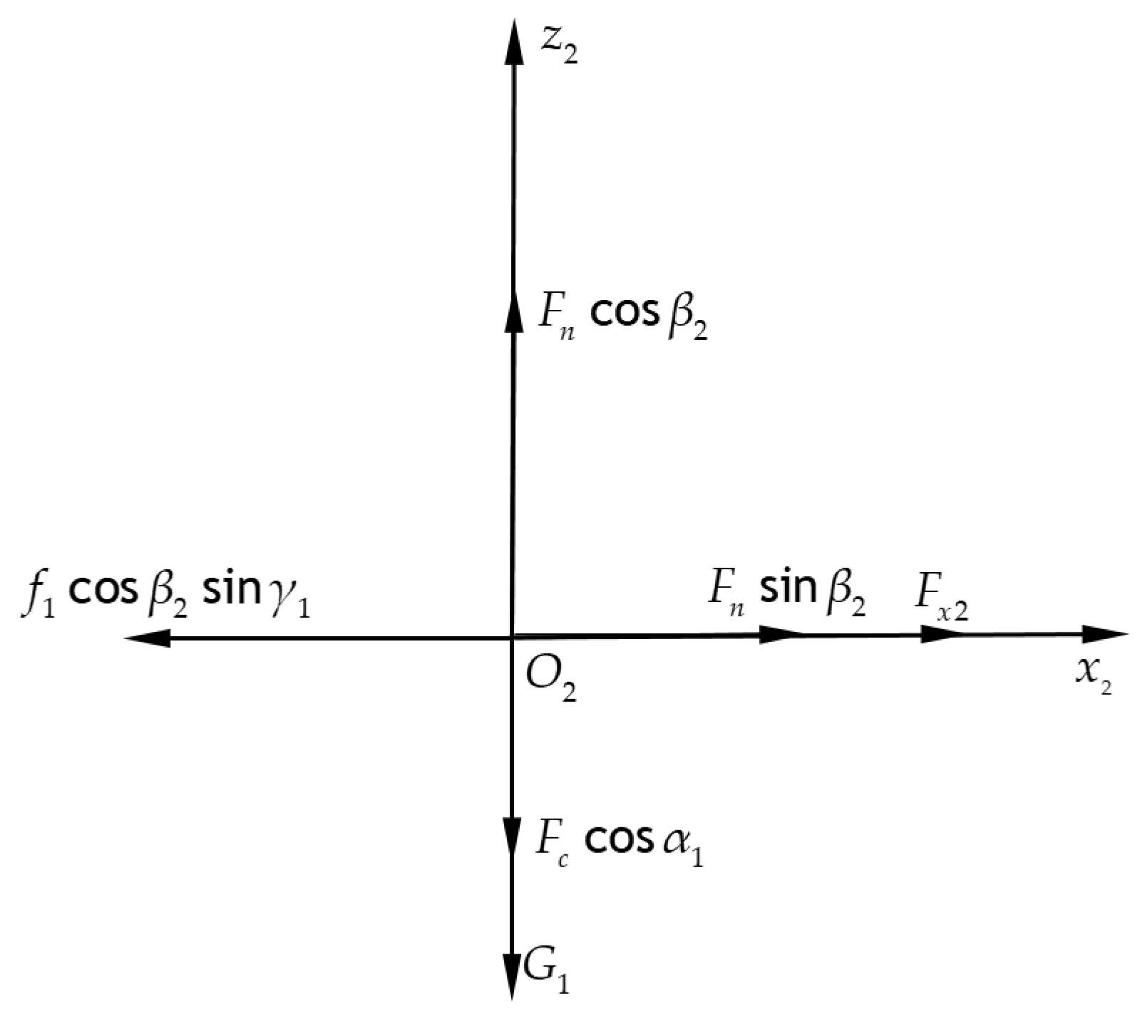
The stress of soil particles in coordinate system is decomposed into the coordinate system, as shown in Figure 13, the resultant force of soil particles along the direction of and are respectively
Where is rotation angle of cutter shaft when soil particle is detached,(°)
is angle between surface of and tangent edge of rotary tillage blade,(°)
1 is angle between projection ofon the surface of and axis,(°)
Fx2 is the resultant force of soil particles along the axis, (N)
Fz2 is the resultant force of soil particles along the axis, (N)
Figure 13.
Stress of soil particles in coordinate system.
The expressions of centrifugal force Fc, gravity G1 and friction f1 are put into Equation (23) to obtain
Where m is mass of soil particles (kg)
R is rotation radius of soil particle movement (mm)
is friction factor between soil particle and surface of rotary tillage knife
g is acceleration of gravity(m/s2)
is angle of tangent edge bend
In Equation (24), the relation between ( the surface of and the tangent edge of the rotary tillage knife) and (the bending angle of the tangent edge) is, and the angle of the tool shaft α1 ranges from 0° to 90°[25].
In order to determine the axial motion displacement conditions of soil particles, it is necessary to determine the motion process after the action of rotary tillage knife on soil particles. Setting the action time of rotary tillage knife on soil particles as t1, and the component velocity along the direction of at the moment when the soil particles leave the positive section of rotary tillage blade as and the component velocity along the direction of as , it can be obtained from the momentum theorem
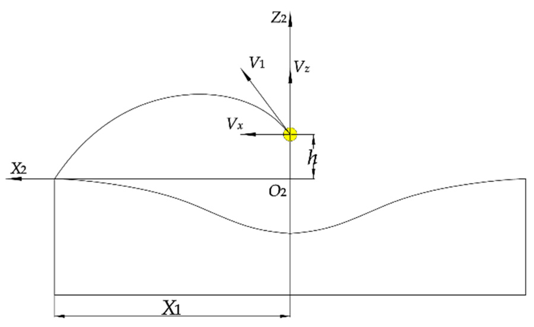
The motion process of soil particles on the surface of is shown in Figure 14. Suppose the vertical height between the moment when soil particles are thrown out and the head of the seedling is h, the component velocity on the surface of is V1, the rising height of soil particles after being thrown out is hz, and the displacement of soil particles along the direction of is X1, and without considering the air resistance, then the time displacement relation is
Where tz is the time it takes for soil particles to fall to the head of the seedling after being thrown out (s)
tz1 is the time it takes for soil particles to rise to the highest point after being thrown out (s)
tz2 is the time it takes for soil particles to fall from the highest point to the head of the seedling (s)
g is acceleration of gravity(m/s2)
According to agronomic requirements, the maximum displacement of soil particlesalong the direction ofafter being thrown out should meet
l1 is spacing of wide line, which is set to be 700mm according to agronomic requirements
In combination with Equation (25) and (26), the displacement of soil particlesalong the direction of (covering width) can be calculated as
As can be seen from formula (28), factors affecting the landing position of soil particles are the vertical height between the moment when soil particles are thrown out and the head of the seedling(h), the resultant force Fz2 of soil particles along theaxis, the resultant force Fx2 of soil particles along theaxis, and the action time t1 of rotary tillage knife on soil particles.
Figure 14.
Movement process of soil particles on the surface of .
3.4. Film covering device
Figure 15 shows the structure of the film covering device, which is mainly composed of film hanging rod, connecting frame of film hanging rod, film spreading roll, adjusting rod of film spreading roll, connecting rod of film spreading roll, etc. The mulch extends from the hanging rod and is pressed to the V-shaped seedbed by the spreading roll, Both sides of the mulch are guided to the seedbed by the spreading roller and are fitted with the soil, In order to prevent film damage in the mulching process, the two sides of the spreading roll are designed in circular arc, which can not only mulch the film, but also blanket the edge of the film. At the same time, the distance between head of the seedling and film edge ranges from 0~40mm, meeting the agronomic requirements of crop cultivation. The film height of the film spreading roll can be adjusted by changing the vertical position of the adjusting rod of the film spreading roll. Compared with the existing film covering device, the film spreading roll designed in this paper can realize V-shaped film coating and edge pressing under the premise of ensuring no damage to the film and improving the film coating quality of V-shaped seedbed.
According to agronomic requirements, the seedlings must outcrop on the edge of film in the process of film mulching, so the selection of mulching film needs to meet:
Where L1 is the linear distance from the head of the seedling to the furrow (250mm)
L2 is the width of furrow (200mm)
L is the width of film (mm)
X is distance between outcrop of seedling and film edge, which is set to be 40mm
Taking all the factors into consideration, the width of film is set to be 620mm.
3.5. Seedling head burial and film edge soil-covering device
In order to prevent strong winds from uncovering the film, it is necessary to cover the film edge and furrow with soil[26]. At present, the common film covering device used are disc type, rotary tillage type, straddle type, etc. The disc type and plough-share type are usually given to the priority as they are easily to be adjusted, disassembled and transported in the process of operation. This design adopts the disc type as it can cover the film with soil effectively in low speed, at the same time, the chances of the soil to be piled-up is quite slim. Seedling head burial and film edge soil-covering device is composed of soil-covering disc, U-shaped card and so on. In order to adjust the thickness of soil covered on the film edge and furrow, the soil-covering disc is designed to adjust both the depth of the soil and the margin of the film.
As shown in Figure 16, during the operation of seedling head burial and film edge soil-covering device, it can cover soil on the edge of film; Under the action of gravity, the soil accumulated at the seedling head can backfill ridge furrow and press film[30] to form ridge furrow soil-covering belt. The amount of soil covered on the film edge and ridge furrow plays a very important role in covering soil on the film edge and constructing the mechanization of seedbed. The amount of soil lifted by the disc should be equal to the total amount of covered soil. In order to further improve the performance of the seedling head burial and film edge soil-covering device, it is necessary to carry out theoretical analysis and calculation of the amount of covered soil.
Under the guidance of soil-covering disc, the edge of the film and ridges are covered with soil, and at last 4 pieces of film edge soil-covering belts and 2 pieces of ridge and furrow soil-covering belts are formed, each position of the mulched seedbed with a length of 1000mm is calculated.
Setting the amount of soil covered on the film edge as , and the amount of soil covered on the ridge and furrow as , then calculating the formula according to the amount of covered soil[31]
Where γ is bulk density of soil, which is set to be 1300kg/m3[32]
LS is length of mulched seedbed, which is set to be 1000mm
B1 is the width of film edge covered with soil (B), which is set to be 50mm
H1 is thickness of film edge covered with soil (B), which is set to be 30mm
It can be calculated from Equation (30) Q3=1.95kg
Similarly, the amount of soil covered on furrows is
Where B2 is width of ridge and furrow covered with soil, which is 60mm
H2 is thickness of ridge and furrow covered with soil, which is 35mm
It can be calculated from Equation (31) kg
The total amount of covering soil is
It can be calculated from Equation (32) that Qn=17.46kg
The amount of soil lifted by a single soil-covering disk is[33]
Where S2 is the effective cross-sectional area of the soil-covering disc, which is set to be 4.3×10⁻³m2 in this paper
Where Qm is the total amount of soil lifted by the soil-covering disc
It can be calculated from Equation (34)
Qm=22.36kg
It can be seen from Equations (32) and (34) that the total amount of soil lifted by the soil-covering disk Qm is equivalent to the total amount of covered soil needed by the soil-covering belt Qn, meeting the demand of soil- covering on the film edge.
3.6. The transmission system
The transmission system of combined machine for transplanting outcrop of Codonopsis with micro ridge covered with film is shown in Figure 17.
In the field operation, the machine adopts the three-point suspension mode at the rear of the four-wheel tractor and drives the trenching shovel to complete the trenching and ridging of the seedbed. At the same time, as the machine progress, seedbed preparation device would collect soil on ridge and furrow and form two V-shaped seedbeds; While the machine moves forward, the ground wheel is driven to rotate to input the power to the drive shaft of seedling casting device through the chain drive, then the driving shaft of seedling throwing device would rotate to drive seedling throwing device which will work together with drive shaft of seedling throwing device, driven shaft one and the second and third axles of driven shaft two to complete the artificial placement of seedlings; The power output shaft of tractor will input the power to rotary tillage knife of gearbox through the coupling, then rotary tillage knife of gearbox would cut the soil on the seedlings soil-covering belt and throw the soil onto two V-shaped seedbeds; Meanwhile, the mulching film rotates synchronously with the hanging frame, and the spreading film roller would mulch the film evenly and make sure the seedlings outcrop on the edge of film; Then 4 soil-covering disks would work together to cover the seedlings and press film.
In order to meet the agronomic requirements of seedling plant spacing, when the ground wheel rotates for one round, the driving shaft of the seedling casting device would rotate for n times, then
Where z1 is the number of sprocket teeth of the ground wheel shaft, which is set to be 27; z2 is the number of input sprocket teeth of intermediate shaft, which is set to be 13; z3 is the number of output sprocket teeth of intermediate shaft, which is set to be 26; z4 is the input sprocket teeth of driving shaft of the seedling casting device, which is set to be 12.
When the ground wheel rotates for 1 round, the number of seedings (n1) delivered by each seedling casting device is
Where d is the diameter of the driving shaft of the seeding casting device, which is 100mm; D is the spacing between the seedling plates of the seeding casting device, which is taken to be 40mm; ε is the slip rate of the seeding casting device, which is 3%.
From Equation (36), it can be calculated that the seedling spacing X is
d1 is the diameter of the ground wheel (510mm).
By calculating formula (36) and (37), it can be obtained that when the ground wheel rotates for 1 round, the number of seedings delivered by each seedling casting device n1=36, seedling spacing X=44mm.
4. Simulation of rotary tillage covering operation process
4.1. Setting of simulation parameter
Based on the above analysis, it can be seen that the rotary tillage knife adopts external installation method. In order to further determine the feasibility of lateral soil-covering method and verify the soil-covering quality of rotary tillage soil-covering device on seedlings, the discrete element method is used to carry out simulation test analysis on the lateral soil-covering performance of rotary tillage soil-covering device. The specific size of rotary tillage knife is shown in Figure 18. The covered soil particles were modeled as spherical particles, whose diameter was set to be 6mm, Hertz-mindlin(no-slip) was selected for the contact model of soil particle-soil particle, soil particle-rotary tiller and soil particle-seedbed, and the relevant simulation parameters were set as shown in Table 3[31].
In combination with the characteristics of the seedbed, a V-shaped seedbed and soil reflection device are created in SolidWorks, setting the size of V-shaped seedbed (total length × seedbed width × ridge width) to be 3000mm×260mm×200mm and dip angle of the seedbed to be 15°. The V-shaped seedbed is imported into EDEM, and a virtual soil groove is established on the ridge, the basic size of the soil groove is set to be (length × width × height) 1000mm×200mm×300mm, and the virtual plane coexisting with the upper surface of the soil groove is set as a particle factory to generate soil particles at the rate of 3×10⁴ /s with a total number of 3×10⁵, which takes 10s to generate particles. After particles are generated, the soil groove is removed to let particles fall into the ridge freely.
4.2. Simulation process and result analysis
Before the simulation, SolidWorks is used to conduct 1:1 modeling of rotary tillage knife and soil reflection device, then the modeling is imported into EDEM after completion. At the beginning of the simulation, the rotary tillage knife begins to operate at one end of the soil-covering belt of the seedling, as shown in Figure 19a. The forward speed of the rotary tillage knife is set as 0.2m/s, the rotational speed is set to be 300r/min, and the total time is set to be 9s. The stability stage of simulation is shown in Figure 19b.
Figure 20a shows the soil-covering effect of seedbed after simulation of rotary tillage. It can be seen from the simulation results that the rotary tillage covering device can backfill the soil into ridge furrow and form the ridge. At the same time, the covering width (Figure 20b) can reach 350mm, and the covering thickness (Figure 20c) can reach 71mm at the thickest point. The seedbed presents a shape of arc, and the soil particles on both sides of the seedbed is less. The main reason for this is that the soil particles collide with the seedbed in the process of falling, and the seedbed has a certain dip angle. The secondary soil-covering of the seedling can be completed in the subsequent burial of the seedling to cover the soil on the film edge so as to meet the requirements of the thickness of the seedling.
5. Field experiment
5.1. Purpose and scheme design of the experiment
In order to check the working performance of the whole machine in the actual operation process, field working performance test of the prototype was carried out in the test field of Weiyuan County, Dingxi City in March 2023 (Figure 21).
Before the field test, the rototiller crushed soil in the field to ensure that the terrain of the test area was flat. The soil in the field was yellow loam soil, the moisture content was 12.2%, the surface temperature was 6.7℃, and the wind speed of the air near the surface was 1.29m /s. The tractor used to drive the machine was Dongfeng 554 tractor with climbing gear, the Codonopsis seedlings of 6 months were selected as the test seedlings, the average diameter of the seedling head is 3mm and the average length is 110mm. the seedlings were tied with slip-knot before the test, the average number of each bundle is 175.
Performance tests were carried out with the forward speed of the tractor at 0.1 m/s, 0.15 m/s and 0.2 m/s respectively, and the output speed of the rotary tillage knife was 400r/min. At each forward speed, the depth of the rotary tillage knife was fixed at 220mm and the target seedling spacing was set at 4.4cm. Three groups of tests were carried out at each operating speed. Referring to JB/T 10291-2013 "Standard for dryland planting machinery", the standard deviation of seedling spacing, coefficient of variation of seedling spacing, qualified rate of film side outcrop, qualified rate of planting depth and planting posture were selected to comprehensively evaluate the accuracy of seedling spacing and planting quality of the prototype.
5.2. Accuracy of seedling spacing
The intersection point between the head of a Codonopsis seedling and the seedbed is the planting point of the seedling, and the projection distance of the planting point of two adjacent Codonopsis seedlings on the edge of the film is the planting spacing of the two Codonopsis seedlings. The planting distance Xi of each group of Codonopsis seedlings is measured, and the accuracy of the seedling spacing is evaluated by the coefficient of variation, and the test results of the accuracy of seedling spacing are shown in Table 4.
5.3. Qualified rate of planting depth, planting posture and film side outcrop
In order to measure the planting depth, planting posture and outcrop distance on the membrane side of Codonopsis seedlings, before data collection, the horizontal distance Ls between the seedling head and the membrane edge after the membrane edge is vertically downward and the covering soil is set as the measurement standard for the membrane side outcrop. The angle between the naked seedling and the horizontal plane is set as, and the distance between the deepest part of the naked seedling and the ridge surface is measured as (Figure 22).
According to the agronomic requirements of Codonopsis seedling transplanting, when the planting depth meets the standard , the planting depth can be regarded as qualified. When the angle between the naked seedling and the horizontal plane meets the standard, the planting posture can be regarded as qualified. When the horizontal distance between the seedling head and the membrane edge meets the standard, film side outcrop can be regarded as qualified. Suppose the total number of planted seedlings is Nt, the number of seedlings which meet the standard of planting depth is Ns, the number of seedlings meeting the standard of planting posture is Nz,the number of seedlings which meets the standard of film side outcrop is Nl, then the calculation method of qualified rate of planting depth Ps, the qualified rate of planting posture Pz and the qualified rate of the film side outcrop Pl are respectively as followings
The test results obtained from the above formula are shown in Table 5.
5.4. Discussion of test results
In the process of field test, the prototype can complete the operation process of seedbed preparation, seeding casting, rotary tillage soil-covering, film covering outcrop and film edge soil-covering at one time when the target seedling spacing is set at 4.4cm and the forward speed is 0.1, 0.15 and 0.2 m/s. When the machine moves forward at the speed of 0.1m/s, the average planting spacing was 4.56cm, the average variation coefficient of planting spacing was 0.08%, the average qualified rate of planting depth was 95.83%, the average qualified rate of planting posture was 94.17%, and the average qualified rate of film side outcrop was 93.33%. When the forward speed of the machine was 0.15m/s, the average planting spacing was 4.87cm, the average variation coefficient of planting spacing was 0.19%, the average qualified rate of planting depth was 92.5%, the average qualified rate of planting posture was 89.17%, and the average qualified rate of film side outcrop was 88.33%. When the forward speed of the machine was 0.2m/s, the average planting spacing was 4.78cm, the average variation coefficient of planting spacing was 0.40%, the average qualified rate of planting depth was 90.83%, the average qualified rate of planting posture was 84.17%, and the average qualified rate of film side outcrop was 84.17%. While the machine moves forward at the speed of 0.1, 0.15, 0.2m /s, referring to JB/T10291 -- 2013 "Standard for dryland planting machinery", variation coefficient of planting spacing is less than or equal to 20%, qualified rate of planting depth is greater than or equal to 75%, variation coefficient of planting spacing and qualified rate of planting depth both have reached the standard requirements. The variation coefficient of planting spacing becomes larger with the increase of forward speed, and the qualified rate of planting depth decreases with the increase of forward speed, indicating that the speed of prototype operation has a great influence on the seedling spacing and planting depth. There is no relevant standard requirements about qualified rate of planting posture and film side outcrop at present, so the qualified rate cannot be evaluated. It can be seen from the test results that qualified rate of planting posture and film side outcrop is greatly affected by the speed of machine and decreases with the increase of operation speed. It can also be concluded from the field test results that when the forward speed of the prototype is 0.1m/s, the operating performance is better than that of 0.15m/s and 0.2m/s.
6. Conclusion
(1) According to the agronomic requirements of Codonopsis membrane-side outcrop cultivation, a kind of combined machine for transplanting Codonopsis outcrop on micro ridge covered with film was designed, which can complete the seedbed preparation, seeding casting, rotary tillage soil-covering, film covering outcrop, seedling head burial and film edge soil-covering at one time. The machine is compact in structure and high in operation efficiency, which solves the problem that the Codondopsis can not be irrigated under the requirements of the dryland film mulching transplanting.
(2) This paper sets the relevant parameters of the core components of the whole machine and studies the working mechanism. In order to ensure the accuracy of transplanting and solve the problem of high labor intensity of manual seeding, the machine adopts the way of manual seeding assisted with mechanical auxiliary seeding to realize the accurate placement of seedlings and automatic feeding; In order to make sure the seedbed to be formed and the amount of soil covered by rotating tillage operation, the installation angle of the shaper is set at 50°; In order to ensure the quality of seeding, the angle between the direction of seeding and the horizontal plane is set at 60°, and the height of seeding is set at 80mm; In order to ensure the range and amount of soil-covering seedlings, the rotary tillage knife is used to cut the soil, which makes it possible to adjust to the range and amount of soil- covering seedlings; While mulching device works, it can bury seedling head and cover soil on the edge of film with the assistance of seedling head burial and film edge soil-covering device.
(3) The field test results showed that the variation coefficient of plant spacing and the qualified rate of planting depth reached the standard requirements when the target plant spacing was 4.4cm and the working speed was 0.1, 0.15 and 0.2 m/s. When the working speed of the prototype increased, the plant spacing and planting depth were greatly affected. The qualified rate of the planting posture and the film outcrop was greatly affected by the working speed of the whole machine, and decreased with the increase of the working speed. When the machine moves forward at the speed of 0.1m /s, the average variation coefficient of planting spacing was 0.08%, the average qualified rate of planting depth was 95.83%, the average qualified rate of planting posture was 94.17%, and the average qualified rate of film side outcrop was 93.33%. The working performance was better than that of 0.15m /s and 0.2m /s.
Author Contributions
Conceptualization, W.S. and Z.Z.; software, B.S. and Z.Z.; investigation, B.S., W.S., Z.Z., L.Z., H.L., H.Z, X.L, H.W and P.L.; resources, W.S.; writing—original draft preparation, B.S.; writing—review and editing, W.S., Z.Z.,H.Z., H.L., and B.S.; supervision,., L.Z. X.L. H.Z., H.W. P.L., and H.L.; project administration, W.S.; funding acquisition, W.S. All authors have read and agreed to the published version of the manuscript.
Funding
This work was supported by the Modern Silk Road Cold and Drought Agricultural Technology Support Project(GSLK-2022-12), Gansu Province Agricultural Machinery Equipment Shortcomings Action Project(njyf2023-13-1) and the National Key R&D Plan (2021YFD1100506).
Data Availability Statement
The data presented in this study are available on request from the corresponding author.
Acknowledgments
We fully appreciate the editors and all anonymous reviewers for their constructive comments on this manuscript.
Conflicts of Interest
The authors declare no conflict of interest.
References
- Fang Huiling. Establishment of Codonopsis industrial technology innovation strategic alliance in Gansu Province [N]. Daily Ganws.com - Gansu Economic Daily,2018-10-23.
- Liu D, Gong Y, Zhang X, et al. EDEM Simulation Study on the Performance of a Mechanized Ditching Device for Codonopsis Planting[J]. Agriculture, 2022, 12(8): 1238. [CrossRef]
- Chang Yong. High-yield Cultivation Technology of Codonopsis in Tongwei County[J]. Journal of Gansu Agriculture, 2014 (16) : 68 + 70. https://doi.org/10.15979/j.cnki cn62-1104 / f 2014.16.093.
- Iqbal M Z, Islam M N, Chowdhury M, et al. Working Speed Analysis of the Gear-driven Dibbling Mechanism of a 2.6 kw Walking-type Automatic Pepper Transplanter[J]. Machines, 2021, 9(1): 6. [CrossRef]
- Han L, Mao H, Hu J, et al. Development of a Riding-type Fully Automatic Transplanter for Vegetable Plug Seedlings[J]. Spanish Journal of Agricultural Research, 2019, 17(3): e0205-e0205. [CrossRef]
- Jin X, Li D, Ma H, et al. Development of Single Row Automatic Transplanting Device for Potted Vegetable Seedlings[J]. International Journal of Agricultural and Biological Engineering, 2018, 11(3): 67-75. [CrossRef]
- Yan W, Hu M, Li K, et al. Design and Experiment of Horizontal Transplanter for Sweet Potato Seedlings[J]. Agriculture, 2022, 12(5): 675. [CrossRef]
- Xu Gaowei, Liu Hongxin, FARMAN A C, Fang Huimin, Jian Shichun, He Tengfei. Design and Experiment of Tilting Transplanting Mechanism on Salvia Miltiorrhiza Film [J]. Journal of Agricultural Machinery,2019,50(02):78-89+101. [CrossRef]
- Wu Guangwei, An Xiaofei, Yan Bingxin, Li Liwei, He Yufan, Meng Zhijun. Design and Test Based on Pretreatment of Seedlings with Bare Sweet Potato Seedling Transplanting Machine [J/OL]. Journal of Agricultural Machinery: 1-13 [2022-10-25]. http://kns.cnki.net/kcms/detail/11.1964.S.2022081.html.
- Wang Xujian, Song Jiannong, Liu Cailing, Dong Xiangqian, Wang Jicheng, Zhang Chao. Design and Experiment of Liquorice Tilting Transplanting Ditcher [J]. Journal of Agricultural Machinery,2016,32(13):16-23.
- Na Mingjun, Teng Le, Zhou Kun, Wang Jinwu, Dong Xin, Zhou Maile. Optimization Design and Experiment of Planting Mechanism of Double Operation Machine for Pot seedling Transplanting in dryland [J]. Journal of Agricultural Machinery,2022,53(07):67-73.
- Liu D, Gong Y, Zhang X, et al. Design and Experiment of Dry-Farming Cantaloupe Transplanter under Water[J]. Agriculture, 2022, 12(6): 796. [CrossRef]
- Wang Jinwu, Tang Han, Wang Jinfeng, Lin Nannan, Huang Huinan, Zhao Yi. Design and Experiment of 1DSZ-350 Suspended Paddy Field Single-side Rotary Tillage Suppression and Construction Machine [J]. Journal of Agricultural Engineering,2017,33(01):25-37. [CrossRef]
- Niu Cong, Xu Liming, Duan Zhuangzhuang, Liu Xingxing, Ma Shuai, Yuan Quanchun, Wang Shuoshuo, Yuan Xunteng, Zeng Jian, Chen Chen. Development of Hedge Frame Type Grape Soil Removal and Cold-proof Cloth Recovery Machine in Winter [J]. Journal of Agricultural Engineering,2020,36(02):50-58.
- Ma Shuai, Xu Liming, Xing Jiejie, Yuan Quanchun, Yu Changchang, Duan Zhuangzhuang, Chen Chen, Zeng Jian. Development of Rotary Vane Removal Machine for Grape Vine Soil Burial [J]. Journal of Agricultural Engineering,2018,34(23):1-10.
- Yang Qizhi, He Mingsheng, Shi Lei, Shi Aiping, Zhao Xiaoqi. Study on Interaction between Wine-grape Scraper and Cold-proof Soil [J]. Journal of Agricultural Engineering, 2021,37(22):21-30.
- Hu Minjuan, Zhang Wenyi, Ji Yao, Qi Bing, Xia Qianqian, Li Kun. Influence of Hole Tray Seedling with Biodegradable Pot Transplanting on Pepper Growth Character [J]. Journal of Chinese Agricultural Mechanization, 2020, 41(09) : 57-62. [CrossRef]
- Hu Lianglong, Wang Bing, Wang Gongfu, Yu Zhaoyang, You Zhaoyan, Hu Zhichao, Wang Bokai, Gao Xuemei. Design and Experiment of 2ZGF-2 Compound Planting Machine for Sweet potato [J]. Journal of Agricultural Engineering,2016,32(10):8-16.
- Yuan Ting, Wang Dong, Wen Yongshuang, Zhu Sishuo, Chen Ying, Tan Yuzhi. Design and Experiment of Air-blown Vibration Compound Seedling Taking Mechanism of Vegetable Transplanter [J]. Journal of Chinese Agricultural Mechanization,2019,50(10):80-87.
- Fang Huimin, JI Changying, Farman Ali Chandio, Guo Jun, Zhang Qingyi, Chaudhry Arslan. Analysis of Soil Motion Behavior During Rotary Tillage Based on Discrete Element Method [J]. Journal of Agricultural Machinery,2016,47(03):22-28.
- Tan Haochao, XU Liming, Ma Shuai, Niu Cong, Yan Chenggong, Shen Congcong. Design and Test of Scraper Organic Fertilizer Strip Mixed with the Rotary Tillage Machinery of Fertilizer [J/OL]. Journal of Agricultural Machinery: 1-24 [2022-10-14]. http://kns.cnki.net/kcms/detail/11.1964.s.20220928.1749.0 08.html.
- Liao Qingxi, Du Wenbin, Zhang Qingsong, Lin Jianxin, Chen Zhiling, Zhang Jiqin. Design and Test of Cigar Tobacco Adjustable Seedbed Ridging Membrane Machine [J/OL]. Journal of Agricultural Machinery: 1-13 [2022-12-17]. http://kns.cnki.net/kcms/detail/11.1964.s.20221108.1209. .006.html.
- Sun Jingbin, Liu Qi, Luo Pengxin, Yang Fuzeng, Liu Zhijie, Wang Zheng. Study on Soil Erosion Law of Slope Contour Tilling by Tractor in Mountain [J]. Journal of Agricultural Machinery,2022,53(05):44-56.
- Chen Bin, Chen Xinhua, Chen Xiaobing, Zhu Jiping, Yu Qingxu, Liao Youyi, Liu Yan. Design and Test of Crawler Self-propelled Rotary Tillage Strawberry Ridging Fertilizer Compounding Machine [J]. Journal of Chinese Agricultural Mechanization,2022,43(01):55-60+85. [CrossRef]
- Zheng Kan, Li Yufei, Xia Junfang, Liu Guoyang, Cheng Jian, Kang Qixin. Design and Experiment of Axial Soil Levelling Cutter Roller with Gradual Spiral Lifting Angle for Furrow Rotiller [J]. Journal of Agricultural Machinery,2021,52(05):63-73.
- Sun Wei, Liu Xiaolong, Wang Hucun, Zhang Hua, Wu Jianmin, Yang Xiaoping, Wang Guanping. Design and Experiment of Double Crank Multi-bar Potato Film Punching Planter [J]. Journal of Agricultural Engineering,2018,34(08):34-42.
- Dai Fei, Xin Shanglong, Zhao Wuyun, Liu Fengjun, Xin Bingbang, Ma Mingsheng. Design and Experiment of Potato Sowing Machine with Full Film Surface Covering [J]. Journal of Agricultural Machinery,2017,48(03):76-83+56.
- Shao Chenghui, Kan Junwu, Tang Kehong. Research on Dynamic Parameters of Salt Pan Film Laying Machine Based on Dimension Analysis [J]. Journal of Agricultural Machinery,2003(01):121-123.
- Dai Fei, Song Xuefeng, Zhao Wuyun, Wei Wancheng, Zhang Fengwei, Ma Haijun. Design and Experiment of Micro-ridge Soil Covering Machine [J]. Journal of Agricultural Machinery,2020,51(03):97-105+129.
- Li Shangping, Pan Jiafeng, Zhong Jiaqin, Huang Zongxiao, Gan Fangfang. Design and Experiment of Ditch Cutter for Sugarcane Horizontal Planter Based on Effective Seed Dropping Space [J]. Journal of Agricultural Machinery,2022,53(07):162-170.
- Dai Fei, Zhang Shilin, Song Xuefeng, Zhao Wuyun, Ma Haijun, Zhang Fengwei. Design and Experiment of a Combined Plastic-film Mulching Machine on Double Ridges and Double Width [J]. Journal of Agricultural Machinery,2020,51(05):108-117.
- Sun Wei, Liu Xiaolong, Shi Linrong, Zhang Hua, Liu Quanwei, Wu Jianmin. Soil Covering Characteristics of Scraper Lift Belt Film Covering Device[J]. Journal of Mechanical Engineering,2016,52(07):38-45.
- Shi Linrong, Yang Xiaoping, Zhao Wuyun, Sun Wei, Li Rongbin, Sun Bugong. Design and Experiment of a Combined Potato Sowing Machine with Throwing and Lifting Interfilm Soil-covering [J]. Journal of Agricultural Machinery,2018,49(06):129-137.
Figure 1.
Schematic diagram of the cultivation mode of Codonopsis outcrop on micro ridge covered with plastic film. 1. Ridge body 2. Head of Codonopsis 3. Root of Codonopsis 4. Outcrop area on membrane side 5. Ridge soil-covering belt 6. Mulch 7. Film edge 8. Rain collecting surface.
Figure 1.
Schematic diagram of the cultivation mode of Codonopsis outcrop on micro ridge covered with plastic film. 1. Ridge body 2. Head of Codonopsis 3. Root of Codonopsis 4. Outcrop area on membrane side 5. Ridge soil-covering belt 6. Mulch 7. Film edge 8. Rain collecting surface.
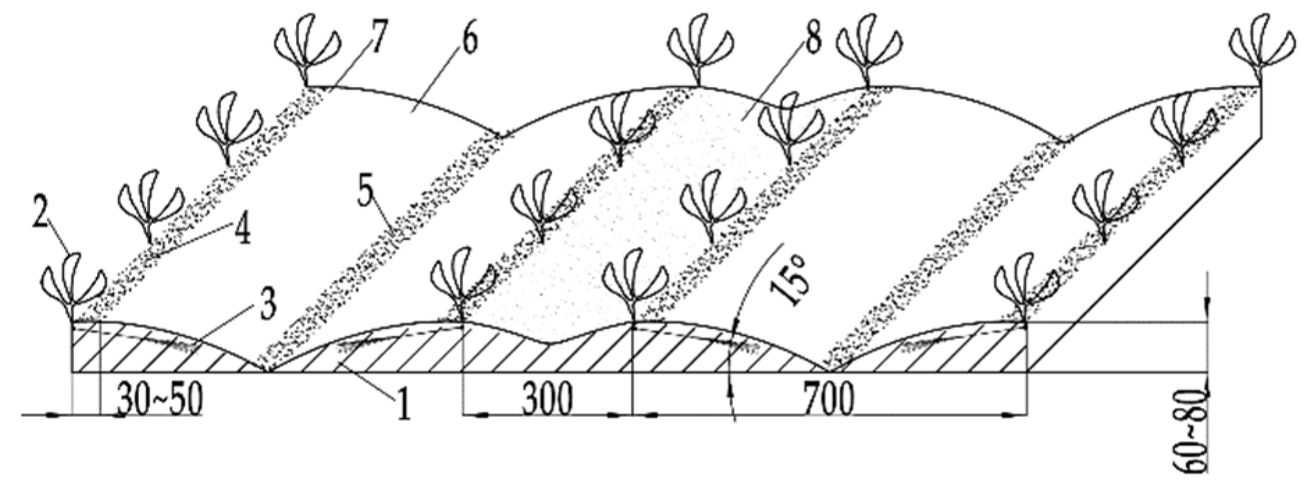
Figure 2.
Overall structure diagram. 1. Hanging device. 2. Seat. 3. Seeding box. 4. Seedling casting device. 5. Frame. 6. seedling head burial and film edge soil-covering device. 7. Spreading film roll. 8. Film hanging frame. 9. Soil reflection device. 10. Gearbox. 11. rotary tillage soil-covering device. 12. Ground wheel. 13. Power transmission device. 14. Seedbed preparation device. 15. Ditching shovel.
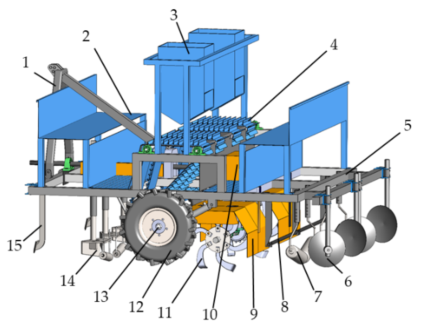
Figure 3.
Structural Diagram of Seedbed Preparation Device. 1. Frame 2. Adjustment lever of shaper 3. Connection lever of shaper 4. Adjusting rod of crushing roll 5. Shaper 6. Crushing roll 7. Adjusting bolt 8. Adjusting nut.
Figure 3.
Structural Diagram of Seedbed Preparation Device. 1. Frame 2. Adjustment lever of shaper 3. Connection lever of shaper 4. Adjusting rod of crushing roll 5. Shaper 6. Crushing roll 7. Adjusting bolt 8. Adjusting nut.
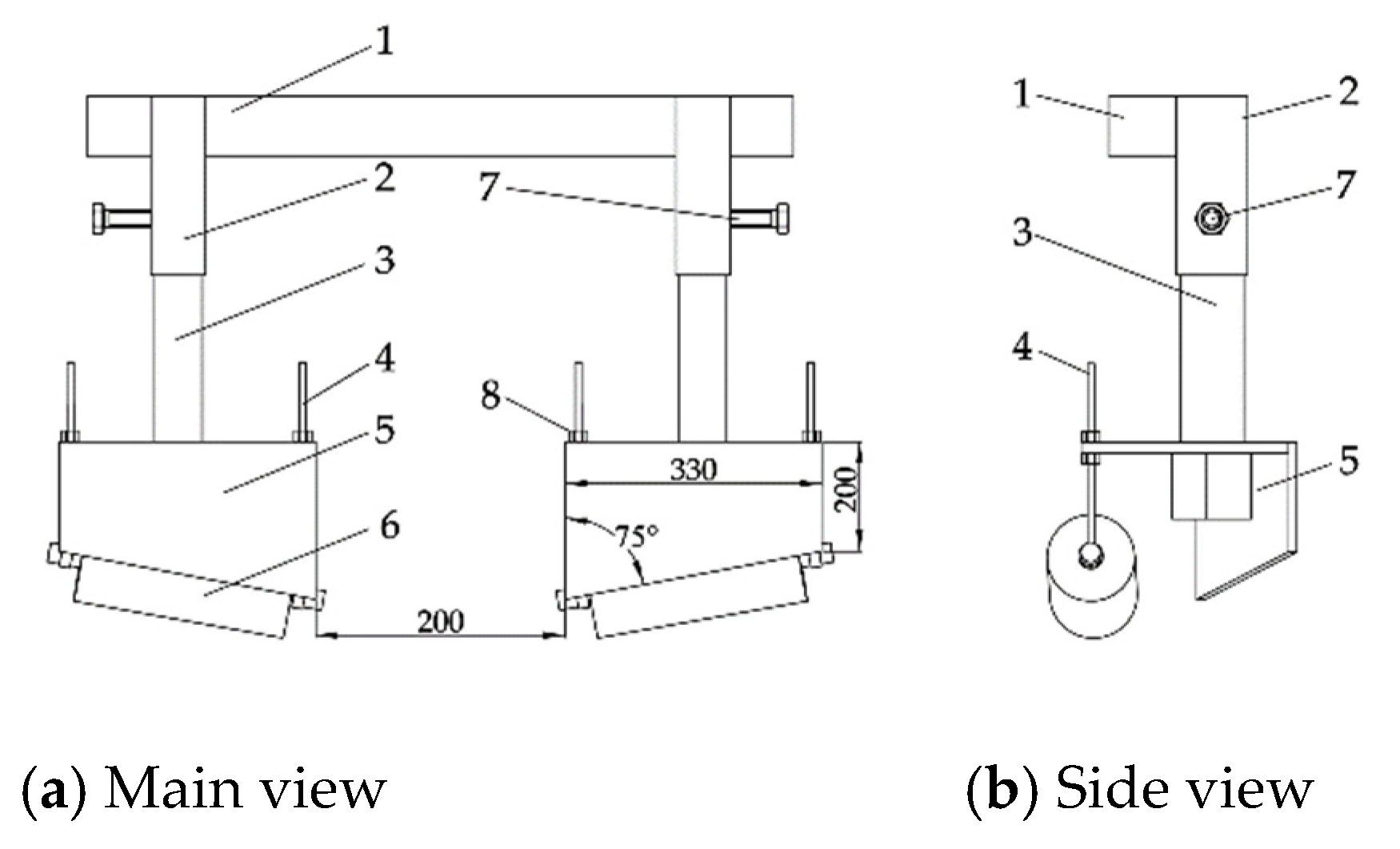
Figure 4.
Schematic Diagram of Operation Process of Seedbed Preparation Device. 1. Seedling soil-covering belt 2. Seedbed 3. Ridge body 4. Non-working area 5. Seedbed preparation device.
Figure 4.
Schematic Diagram of Operation Process of Seedbed Preparation Device. 1. Seedling soil-covering belt 2. Seedbed 3. Ridge body 4. Non-working area 5. Seedbed preparation device.
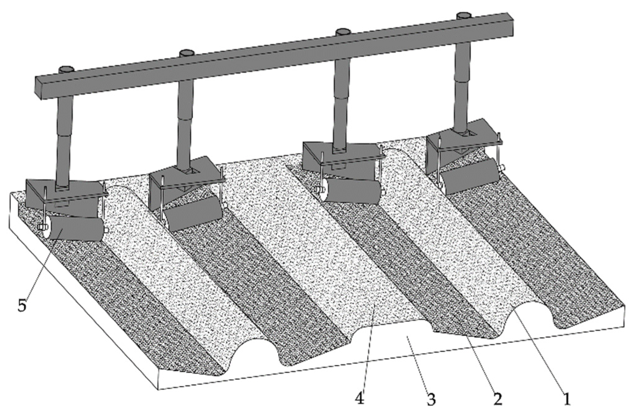
Figure 7.
Structure of seedling casting device. 1. Seedling protection plate 2. Cylindrical pin 3. Connecting block 4. Fixed pin 5. Seedling separation plate 6. Conveyor belt 7. Driving shaft of seedling casting device 8. Driven shaft I 9. Driven shaft II.
Figure 7.
Structure of seedling casting device. 1. Seedling protection plate 2. Cylindrical pin 3. Connecting block 4. Fixed pin 5. Seedling separation plate 6. Conveyor belt 7. Driving shaft of seedling casting device 8. Driven shaft I 9. Driven shaft II.
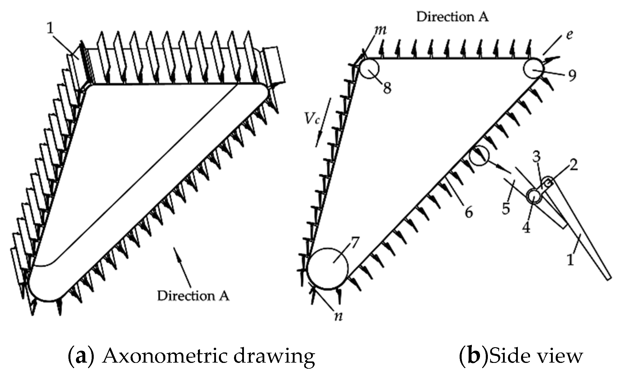
Figure 8.
Analysis of seedling movement in the air. 1. Seedling protection plate 2. Conveyor belt 3. Cross section of seedbed 4. Seedbed 5. Seedling soil-covering belt 6. Driving shaft of seedling casting device 7. Seedling.
Figure 8.
Analysis of seedling movement in the air. 1. Seedling protection plate 2. Conveyor belt 3. Cross section of seedbed 4. Seedbed 5. Seedling soil-covering belt 6. Driving shaft of seedling casting device 7. Seedling.
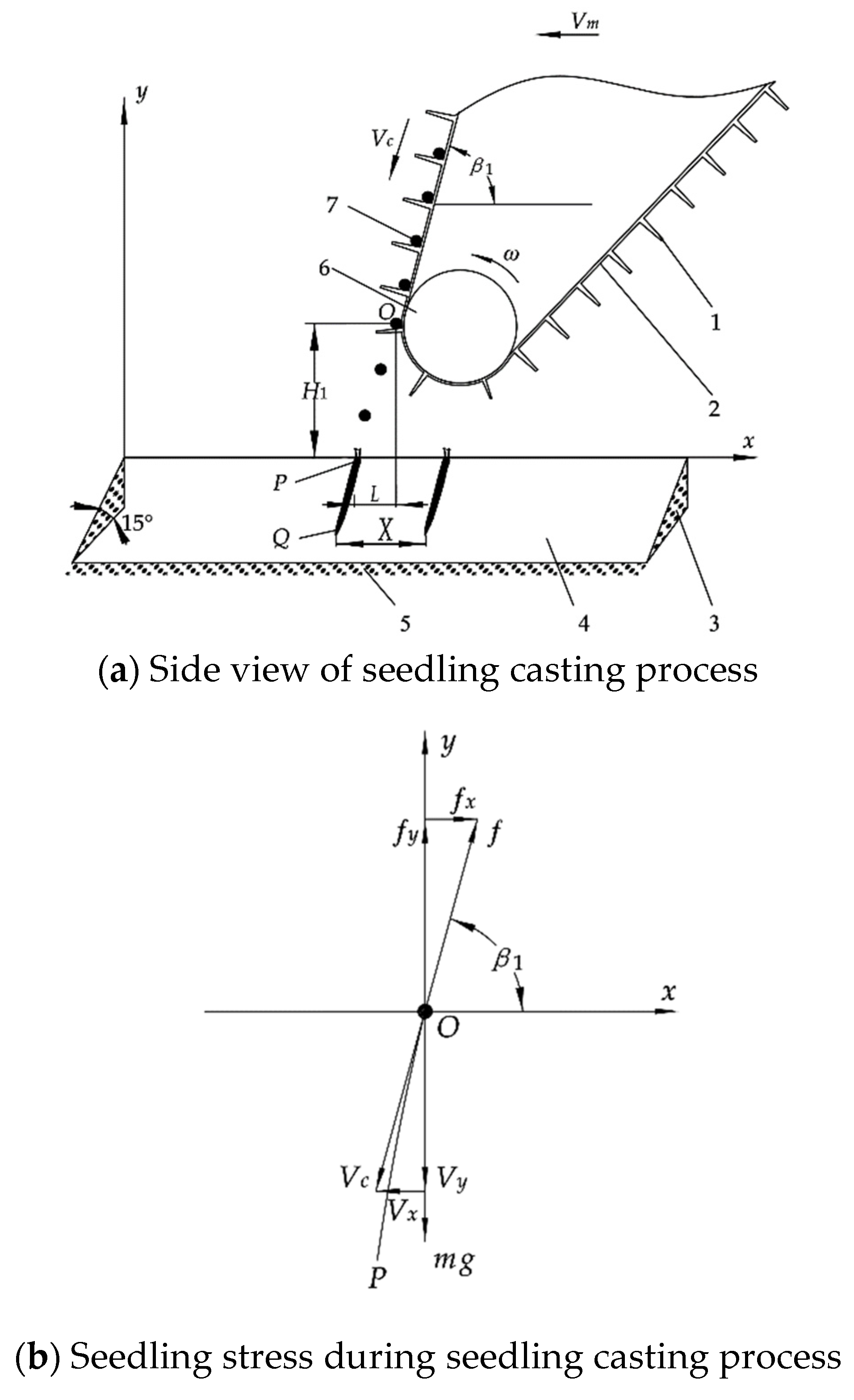
Figure 9.
Schematic diagram of rotary tillage knife arrangement.
Figure 10.
Schematic diagram of rotary tillage knife throwing soil. 1. Seedlings 2. Seedling soil-covering belt 3. Ridges 4. Soil particles 5. Seedbed 6. Rotary tillage knife.
Figure 10.
Schematic diagram of rotary tillage knife throwing soil. 1. Seedlings 2. Seedling soil-covering belt 3. Ridges 4. Soil particles 5. Seedbed 6. Rotary tillage knife.
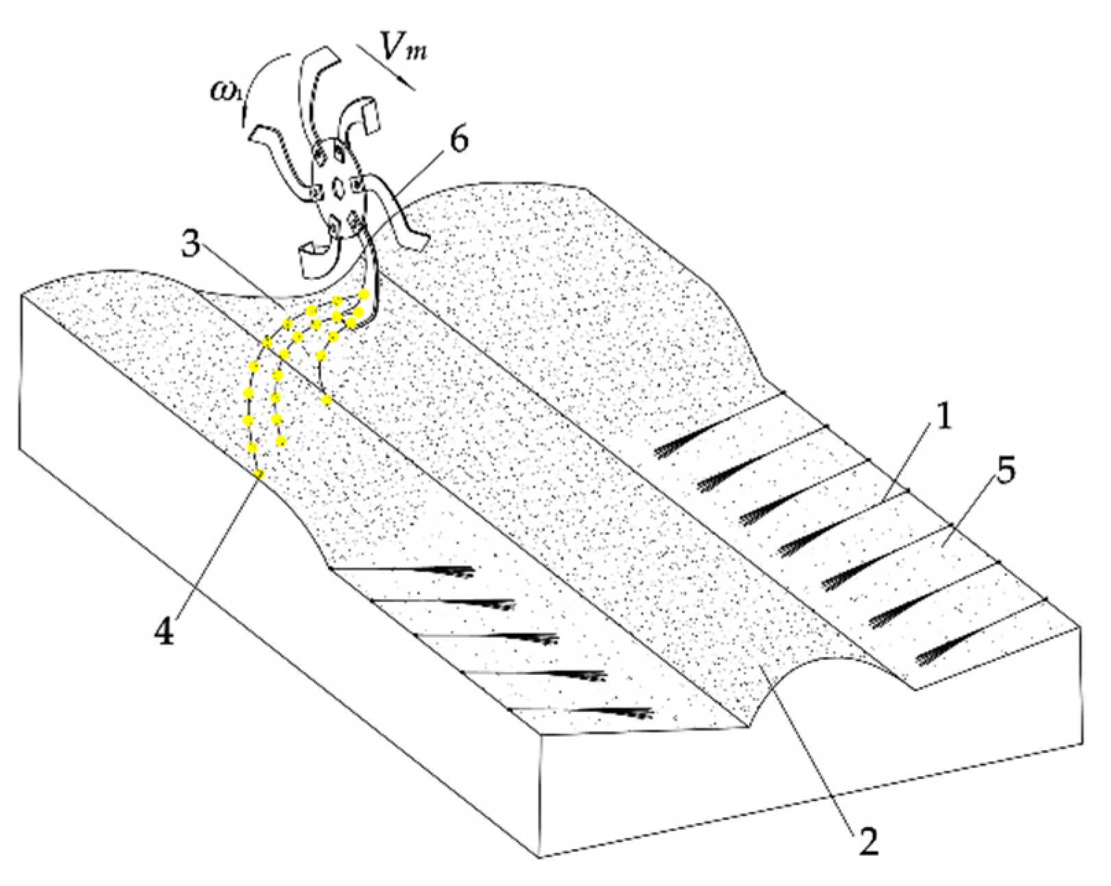
Figure 11.
Area of soil cut by rotary tillage blade.
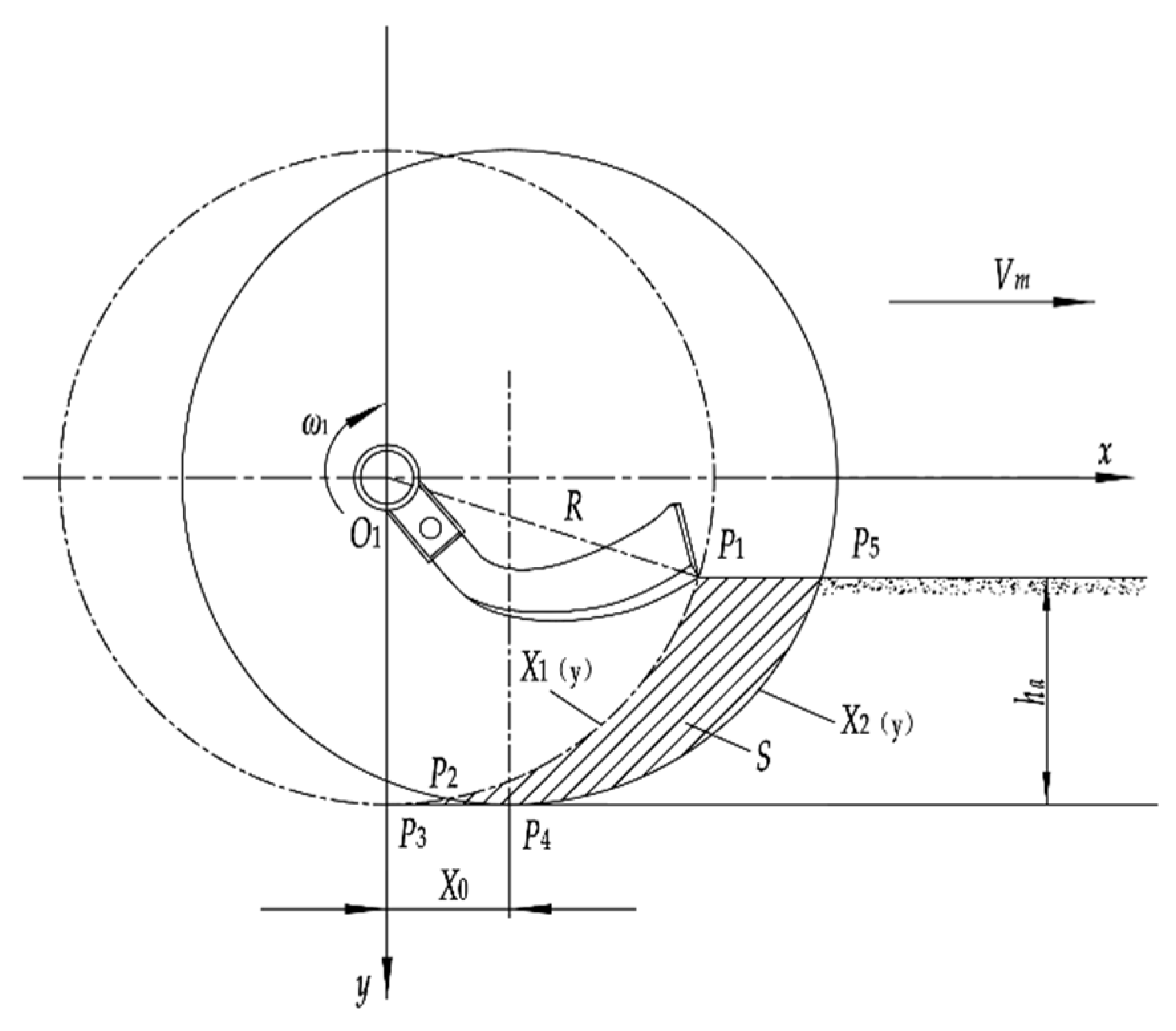
Figure 12.
Spatial force of a single soil particle.
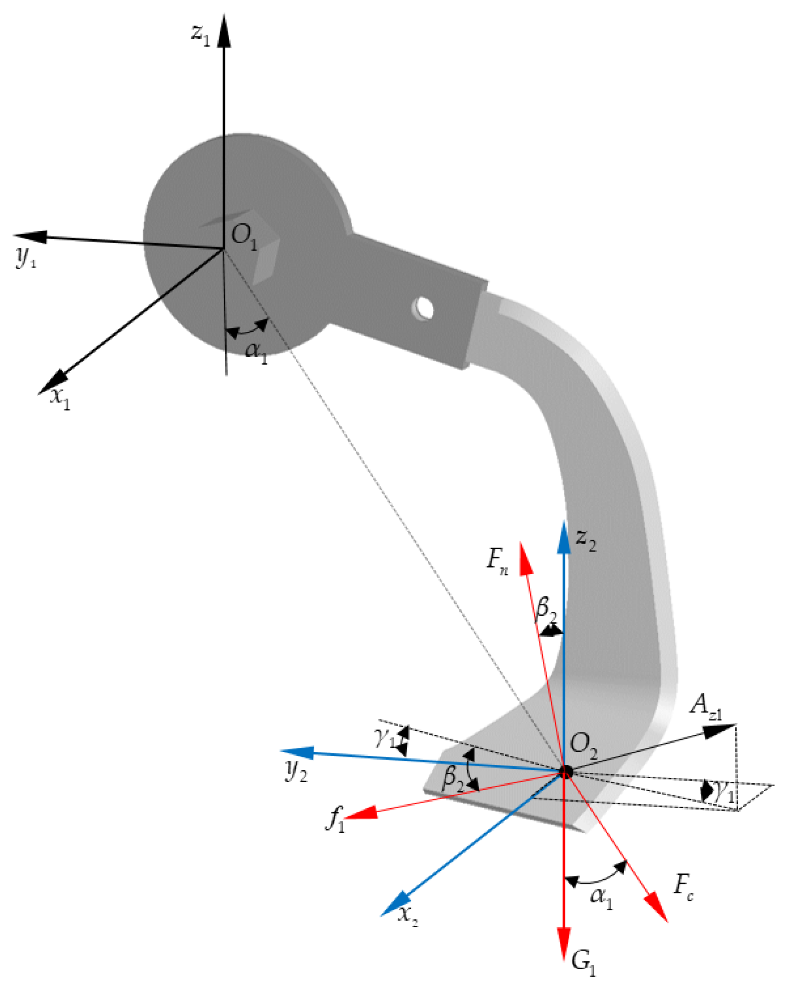
Figure 15.
Structural diagram of film covering device. 1. Adjusting rod of film spreading roll 2. Film hanging rod 3. Plastic film 4. Mulching area on furrow 5. Rain collecting surface 6. Seedlings 7. Film side outcrop 8. Film spreading roll 9. Connecting rod of film spreading roll 10. Connecting frame of film hanging rod 11. Frame.
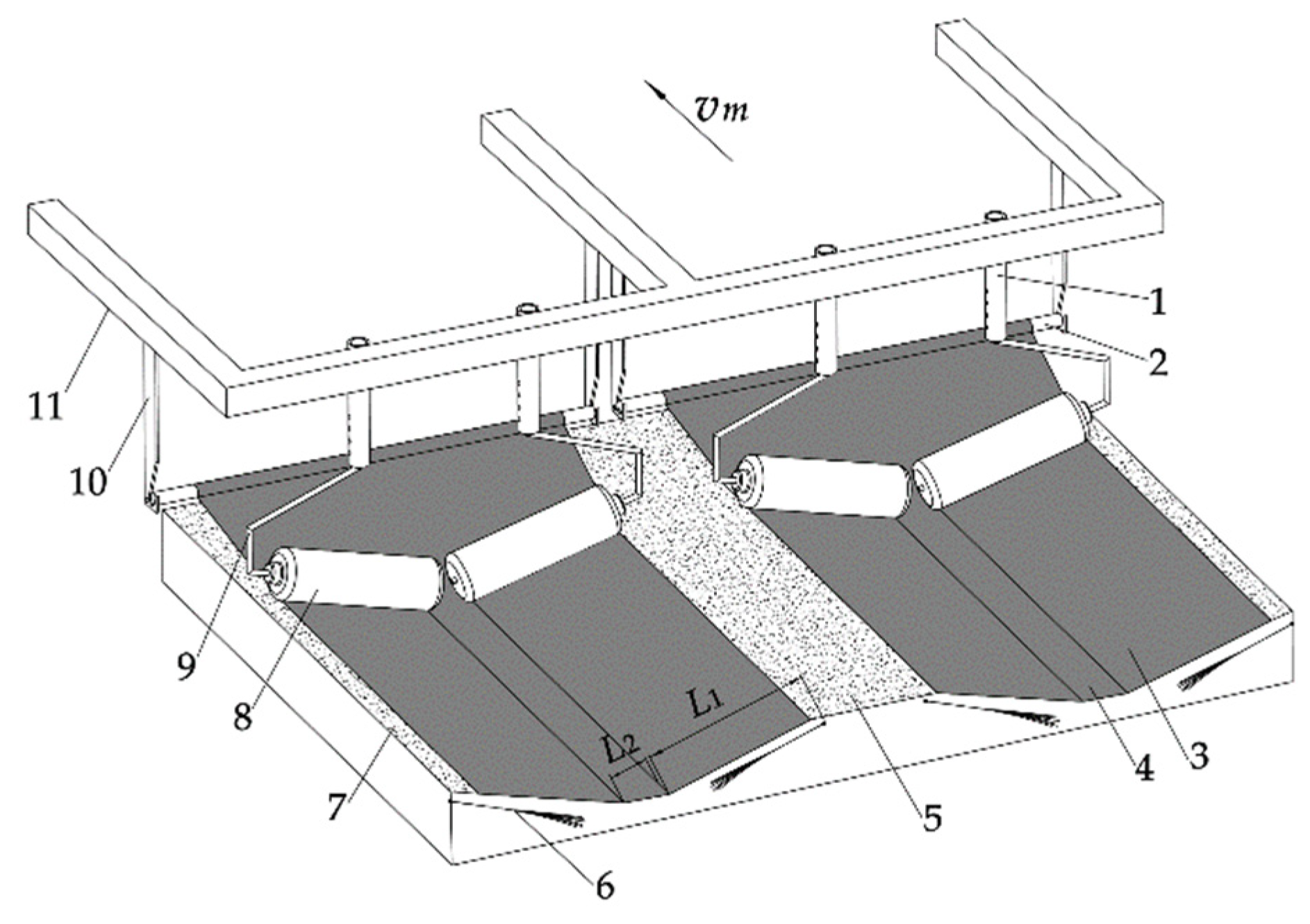
Figure 16.
Schematic diagram of operation process of seedling head burial and film edge soil-covering device. 1. Ridge body 2. Film edge soil-covering belt 3 Field soil 4. Soil-covering belt on ridge and furrow 5 Rainwater collection surface 6 Plastic film 7 Frame 8 U-shaped card 9. Soil-covering disc.
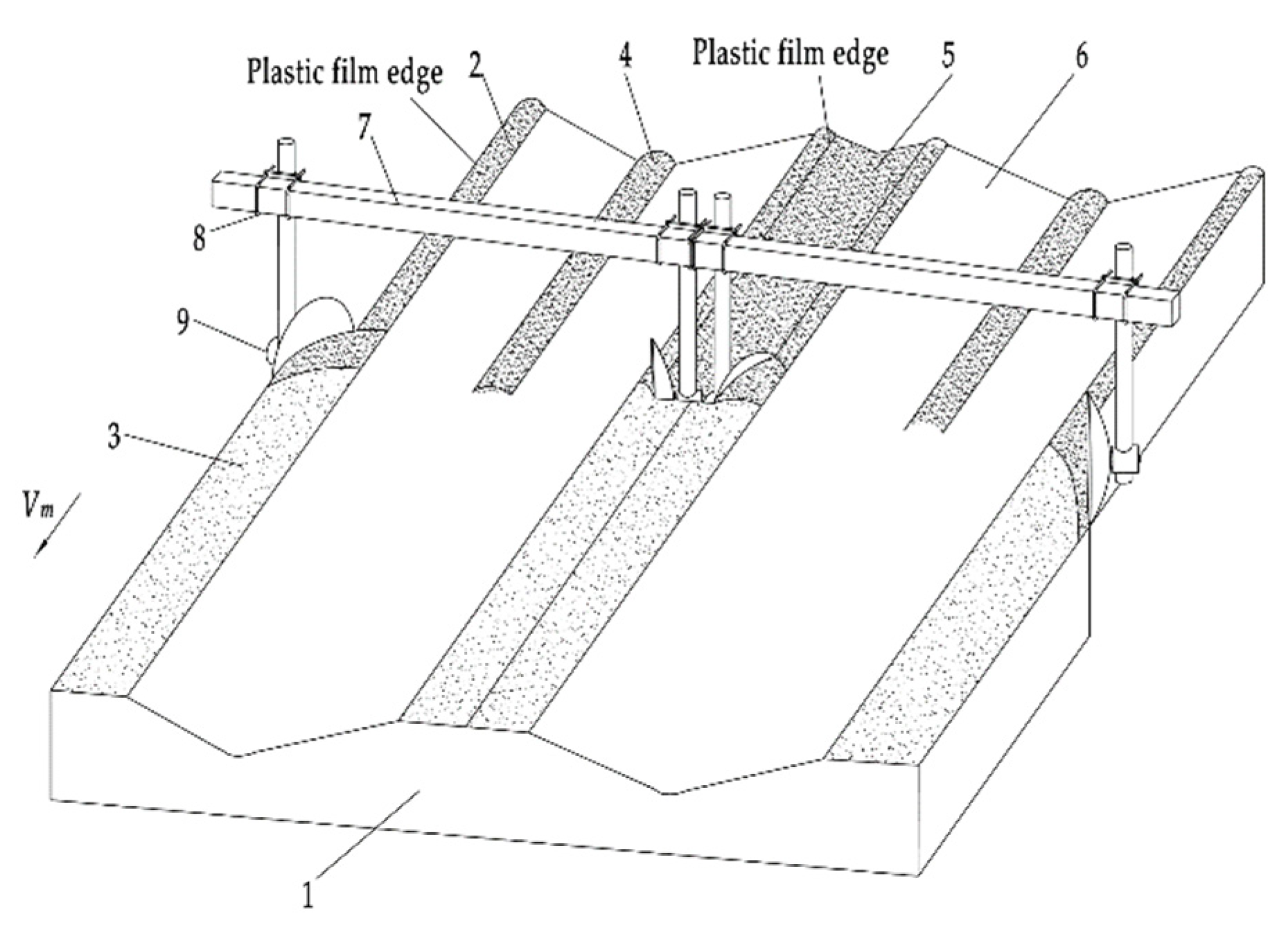
Figure 17.
Schematic diagram of transmission system of combined machine. 1. Coupling 2. Trenching shovel 3. Seedbed preparation device 4. Driving shaft of seedling casting device 5. Driven shaft I 6. Ground wheel 7. Seedling casting device 8. Driven shaft II 9. Chain drive 10. Gearbox 11. Cutter shaft 12. Rotary tillage soil-cutting set 13. Hanging frame 14. Film spreading roller 15. Soil-covering disc.
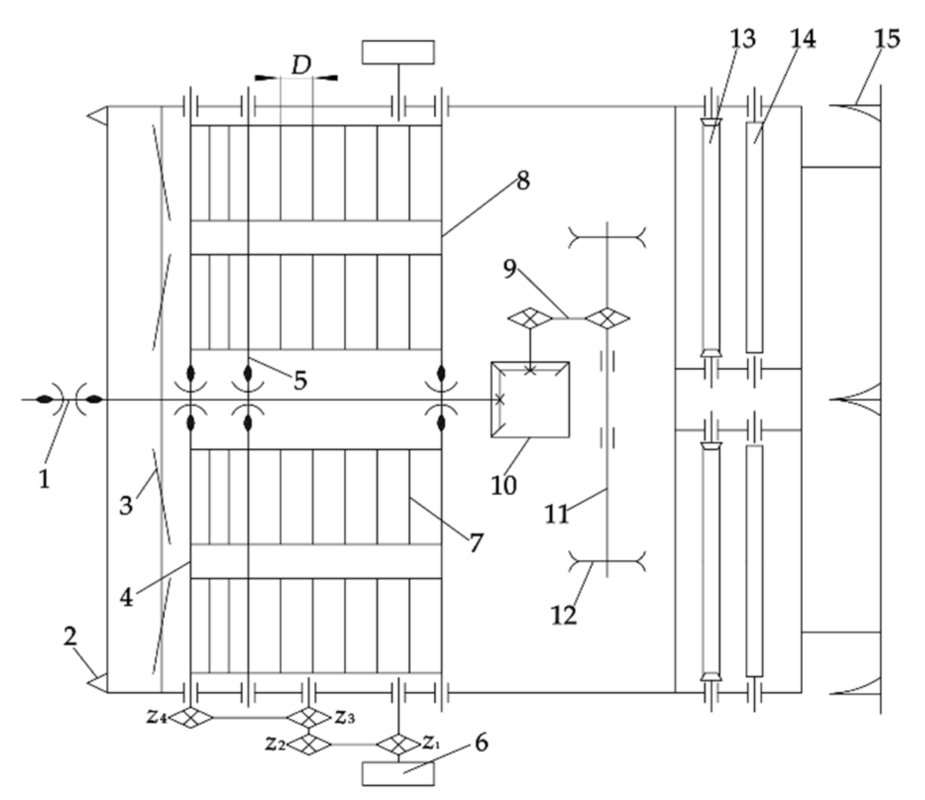
Figure 18.
Structure diagram of rotary tillage knife.

Figure 19.
Simulation process.
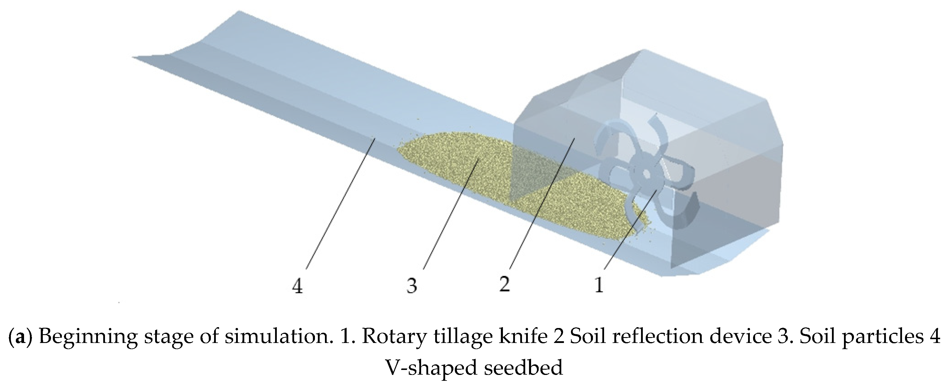
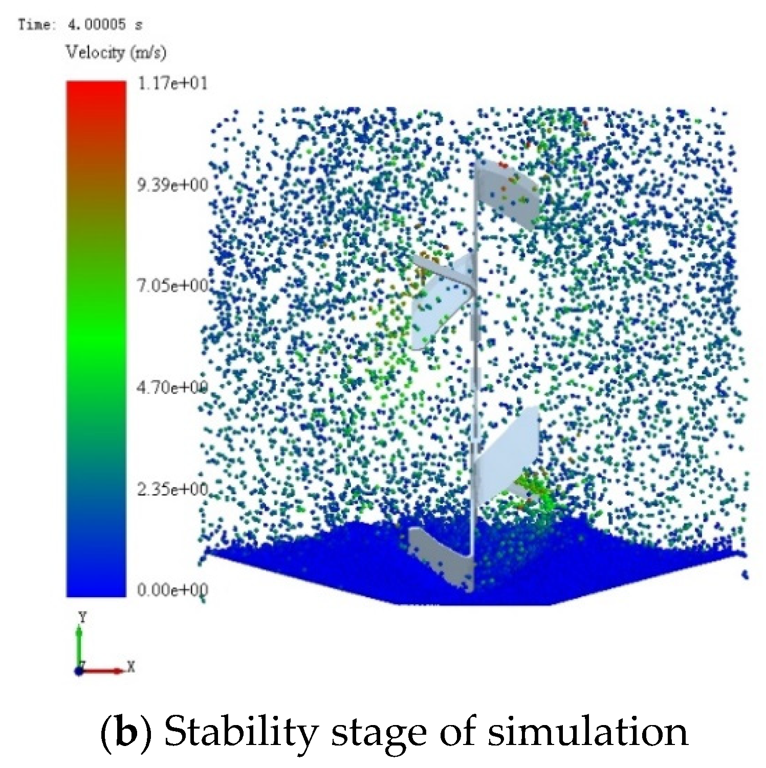
Figure 20.
End of simulation.

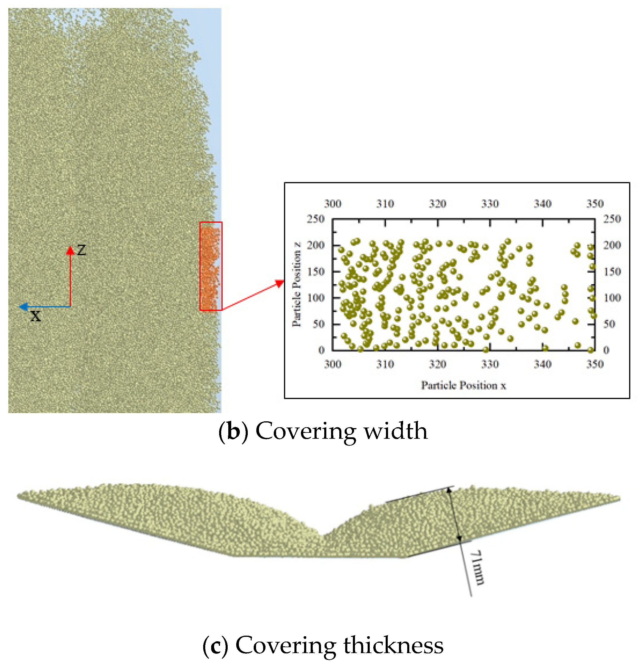
Figure 21.
Effect of Field Experiment.
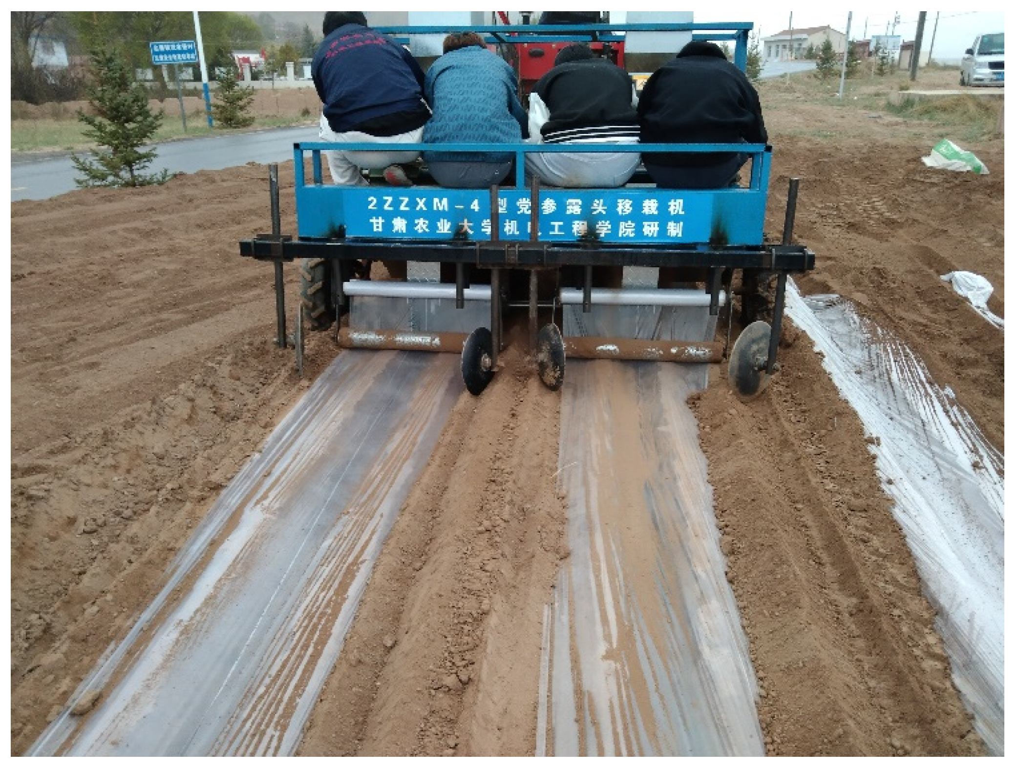
Figure 22.
Schematic diagram of measurement of planting posture.
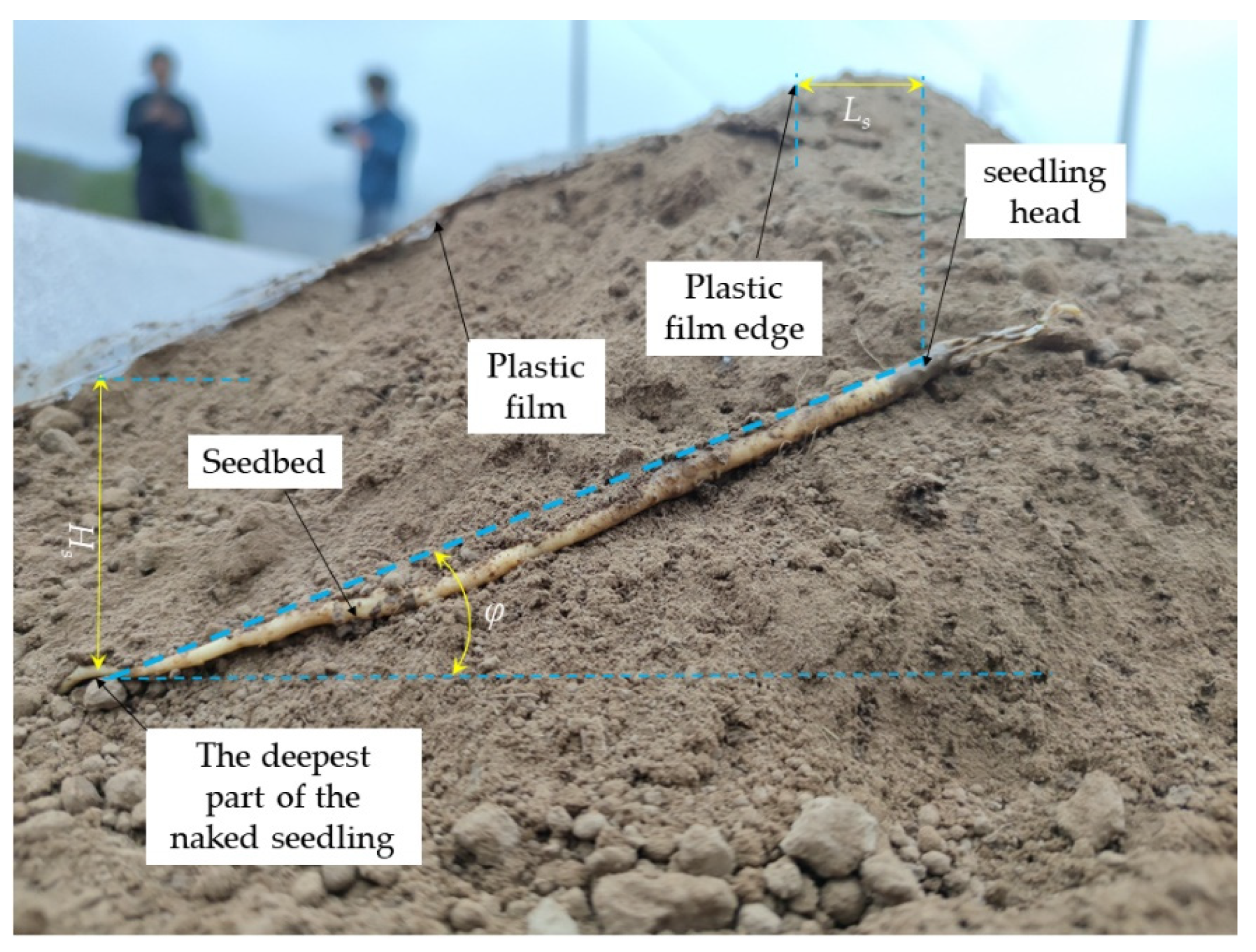

Table 1.
Manual transplanting operation procedure of Codonopsis seedlings.
| NO | Process | Picture | Requirements |
| 1 | Seedbed preparation |  |
The seedbed is tilted 10° to 20° |
| 2 | Setting seedlings | 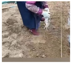 |
The head of the seedlings is aligned and the spacing is 40~60mm |
| 3 | Covering the seedlings with soil (burying the seedlings) |  |
The thickness of covering soil is 40~80mm, and the soil should be scattered evenly |
| 4 | Mulching | 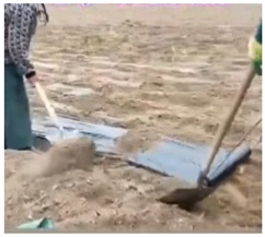 |
The distance between film edge and head of the seedling is 0~40mm |
| 5 | Coverig the membrane edge and seedlings with soil | 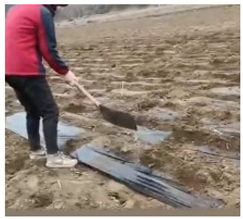 |
The amount of soil covering for a length of 1000mm should not be less than 1.5kg |
Table 2.
Main technical parameters of operating machine.
| Parameters | Numerical Values |
| Machine dimensions (length × width × height)/(mm × mm ×mm) |
2297×2107×1655 |
| Auxiliary power/kw | 44.1 |
| Overall quality/kg | 512 |
| Seedling placement method | Manual seedling placement |
| Seedling outcrop distance/mm | 0~40 |
| Plant spacing/mm | 44 |
| Productivity/(hm2·h-1) | 0.45~0.65 |
| Number of seeding rows | 4 |
| Angle of inclined planting/° | 15 |
| Covering thickness of seedlings/mm | 40~80 |
| Number of plastic films | 2 |
| The width of plastic film /mm | 620 |
| Suspension mode | Three-point suspension |
Table 3.
Parameters of simulation model.
| Project | Parameters | Numerical value |
| Soil particles, V-shaped seedbeds |
Poisson’s | 0.4 |
| ratio shear modulus /Pa | 1.0×10⁶ | |
| Density /(kg.m-3 ) | 1364 | |
|
Rotary tillage knife |
Poisson’s | 0.28 |
| ratio shear modulus /Pa | 3.5×10¹⁰ | |
| Density /(kg.m-3 ) | 7850 | |
| Soil particles - soil particles, seedbeds | Coefficient of recovery | 0.21 |
| Coefficient of static friction | 0.68 | |
| Coefficient of dynamic friction | 0.27 | |
| Soil Particles - Rotary tillage knife | Coefficient of recovery | 0.54 |
| Coefficient of static friction | 0.68 | |
| Coefficient of dynamic friction | 0.13 |
Table 4.
Test results of seedling spacing accuracy.
| Number | Forward speed (m/s) | Average seedling spacing /cm | Standard deviation/cm | Coefficient of variation /% |
|---|---|---|---|---|
| 1 | 0.10 | 4.54 | 0.40 | 0.09 |
| 2 | 0.10 | 4.57 | 0.41 | 0.09 |
| 3 | 0.10 | 4.56 | 0.31 | 0.07 |
| 4 | 0.15 | 4.85 | 0.88 | 0.18 |
| 5 | 0.15 | 4.91 | 0.86 | 0.17 |
| 6 | 0.15 | 4.84 | 1.02 | 0.21 |
| 7 | 0.20 | 4.90 | 1.73 | 0.35 |
| 8 | 0.20 | 4.80 | 2.16 | 0.45 |
| 9 | 0.20 | 4.65 | 1.89 | 0.41 |
Table 5.
Results of planting test.
| Number | Forward velocity (m/s) | Number of plants | Number of qualified plants for planting depth | Number of qualified plants for planting posture | Number of qualified plants on membrane side outcrop | Qualified rate of planting depth /% | Qualified rate of planting posture /% | Qualified rate of film side outcrop /% |
|---|---|---|---|---|---|---|---|---|
| 1 | 0.1 | 40 | 38 | 36 | 36 | 95.00 | 90.00 | 90.00 |
| 2 | 0.1 | 40 | 38 | 39 | 38 | 95.00 | 97.50 | 95.00 |
| 3 | 0.1 | 40 | 39 | 38 | 38 | 97.50 | 95.00 | 95.00 |
| 4 | 0.15 | 40 | 37 | 37 | 36 | 92.50 | 92.50 | 90.00 |
| 5 | 0.15 | 40 | 38 | 35 | 35 | 95.00 | 87.50 | 87.50 |
| 6 | 0.15 | 40 | 36 | 35 | 35 | 90.00 | 87.50 | 87.50 |
| 7 | 0.2 | 40 | 36 | 35 | 32 | 90.00 | 87.50 | 80.00 |
| 8 | 0.2 | 40 | 36 | 34 | 35 | 90.00 | 85.00 | 87.50 |
| 9 | 0.2 | 40 | 37 | 32 | 34 | 92.50 | 80.00 | 85.00 |
Disclaimer/Publisher’s Note: The statements, opinions and data contained in all publications are solely those of the individual author(s) and contributor(s) and not of MDPI and/or the editor(s). MDPI and/or the editor(s) disclaim responsibility for any injury to people or property resulting from any ideas, methods, instructions or products referred to in the content. |
© 2023 by the authors. Licensee MDPI, Basel, Switzerland. This article is an open access article distributed under the terms and conditions of the Creative Commons Attribution (CC BY) license (http://creativecommons.org/licenses/by/4.0/).
Copyright: This open access article is published under a Creative Commons CC BY 4.0 license, which permit the free download, distribution, and reuse, provided that the author and preprint are cited in any reuse.


