
Submitted:
03 July 2023
Posted:
04 July 2023
You are already at the latest version
Abstract
The purpose of this study is to apply the convergence-confinement method (CCM) based on the assumption of hydrostatic stress to the surrounding rock excavated in a circular tunnel whose rock mass characteristics meet the requirements of the non-linear Hoek-Brown failure criterion. Based on a consistent and rigorous method of theoretical analysis, a closed-form analytical solution for the stress/displacement of the ground reaction induced by the advancing excavation of the tunnel, especially in the elastic and plastic regions, is derived and investigated under the condition of an isotropic stress state. By taking the value of a confinement loss as an explicit analysis process in an incremental manner, not only is the computationally executable analytical solution achieved, but it can also be performed using a simple spreadsheet. The validity of the analytical solution implemented by the incremental procedure was examined with published data to study the effect of nonlinear failure criteria on the ground reaction curve; in particular the mechanical behavior at the intrados of the tunnel, and the distribution of stress/displacement on the cross-section of the tunnel. A comparison between the published results and the solution proposed in this study, which interprets the closed-form by the incremental procedure, shows consistent and favorable trends.
Keywords:
Tunnel analysis
; non-linear failure criterion
; closed-form solution
; incremental procedure
; confinement loss
; convergence-confinement method
1. Introduction
The convergence-confinement method (CCM) is a systematic approach used in the design and construction of tunnels in rock masses. It recognizes that rock masses tend to deform and converge around an excavated tunnel due to the redistribution of stress. The method aims to control and manage this convergence by providing adequate confinement or support to ensure the stability and safety of the tunnel [1,2]. The method provides a framework for understanding and managing the convergence behavior of the rock mass, while the support design translates this understanding into practical measures to enhance tunnel stability [3,4]. The fundamental concept of the CCM is based on the interaction between the primary and secondary stress fields induced by tunnel excavation. When a tunnel is excavated, the primary stress in the rock mass is redistributed, causing the rock to deform and converge toward the opening. This convergence can lead to displacements, deformations, and potentially unstable conditions if not properly controlled [5,6,7,8,9].
The CCM focuses on achieving three main objectives (shown in Figure 1): (1) Ground reaction curve (GRC) aims to limit the amount of convergence and control the rate at which it occurs. By controlling convergence, the risk of tunnel deformation and failure is reduced. The level of acceptable convergence depends on factors such as the tunnel purpose, ground conditions, support system, and safety requirements [10,11,12,13,14,15]. (2) Support confining curve (SCC) refers to the application of external support to the tunnel walls to counteract the inward movement and maintain stability. This is achieved through the installation of various support systems such as rock bolts, shotcrete, steel ribs, or other reinforcement elements. The support elements help confine the rock mass and distribute the stresses, reducing the convergence and enhancing tunnel stability [16,17,18,19,20,21,22,23]. (3) Confinement loss curve (CLC) emphasizes the importance of an observational approach during tunnel construction. This means continuously monitoring the behavior of the rock mass and adjusting the support measures accordingly. The confinement loss can be obtained by the relationship between convergence measurement and unsupported distance to the tunnel face. It could be a positive scalar, an incremental value, or a function for considering the effect of advancing excavation of the tunnel face [24,25,26,27,28]. By implementing the convergence-confinement method, engineers can effectively manage the convergence behavior of rock masses in tunneling projects. It provides a systematic and proactive approach to ensure the stability and safety of underground excavations [29,30].
The ground reaction curve (GRC) is a concept used in the convergence-confinement method to understand the response of the rock mass and support system to tunnel excavation. It represents the relationship between the convergence (displacement) of the tunnel wall and the applied support pressure. In addition, the failure criterion provides insight into the strength and behavior of the rock mass, which influences the shape and characteristics of the ground reaction curve. In this study, the characteristic of the GRC is investigated and implemented by using the non-linear failure criterion of generalized Hoek-Brown [31,32,33]. The criterion allows engineers to assess the stability of rock slopes or tunnels under different stress conditions, taking into account the strength and quality of the rock mass. This criterion helps engineers evaluate the stability of the rock mass and determine the support requirements during tunneling [34,35,36,37]. By using the generalized Hoek-Brown failure criterion, engineers can estimate the rock mass strength and predict the potential failure mechanisms that may occur during tunneling. This information is crucial in selecting appropriate support systems and determining the required support pressure to control convergence and maintain tunnel stability [38,39,40]. Finally, the generalized Hoek-Brown failure criterion provides a basis for understanding the strength and failure behavior of the rock mass, while the ground reaction curve provides a means to evaluate the actual response of the rock mass and support system during tunneling. The failure criterion informs the design of the support system, and the ground reaction curve validates its effectiveness. Together, these concepts contribute to the overall assessment and management of convergence and confinement in the convergence-confinement method for tunneling projects.
The objective of this paper is, therefore, to present a comprehensive discussion on the non-linear failure criterion of generalized Hoek-Brown on a ground reaction in the convergence-confinement method for the tunnel support design, providing the full set of equations and the details of their derivation, verification, comparison, together with illustrative diagrams of the distribution of stresses/displacements at the intrados and on the cross-sections of the tunnel.
2. Problem description
2.1. Relationship between confinement loss and tunnel advancing excavation effect
As a result of the advancing excavation of the tunnel face, a stress field change occurs in the surrounding rock, which in turn produces the results of stress redistribution and convergence of the excavation face. In other words, the effect of advancing excavation of the tunnel face is the consideration of a change of stresses and displacements caused by tunnel sequential excavation at certain measurement points of an observation section. Applying the tunnel convergence measurement, establishing the functions concerning the effect of advancing excavation of the tunnel face, and providing the procedure to estimate the confinement loss are mainly proposed in this study. In addition, the function of the confinement loss curve (CLC) can be shown in Figure 2, and at a certain distance (z) to the working face, the definition of confinement loss (λz) can be given as [5,6]
Concerning the assumption of the function concerning the effect of advancing excavation of the tunnel face, f(z/R), which can also be called the advancing effect function, can be proposed by the following:
where R is the tunnel excavation radius, λ0 is a confinement loss at the working face (z = 0, point A in Figure 1), and can be given as
2.2. Stress variation around a circular tunnel
The convergence-confinement method is based on the analysis of the stress and strain state that developed in the rock mass around a tunnel. The stresses at the periphery of the tunnel are altered due to the excavation of the tunnel. Therefore, the variation of stresses can be mainly interpreted by the stress gradient which is a difference between the far-field stress and the near-field stress around a tunnel. By using the hypothesis of increments in the numerical analysis, the increment of stresses could take into account the confinement loss λ as a fraction of the stress gradient. This is an important principle concept used by the convergence-confinement method. The variation of stresses can be described by the following representations [5,6]:
(1) Stresses in the far-field (the initial in-situ stresses, r –› ∞): Before opening the tunnel, the stresses in the rock mass are in equilibrium and are the same as the lithostatic stresses and constant in the surrounding medium of the tunnel. Hence, the initial anisotropic stress in the rock mass can be shown as shown in Figure 3, and indicated by the following equation,
where , , and are the initial radial stress, the initial tangential stress, and the vertical stress in the polar coordinates (r, θ ), respectively.
(2) Stresses in the near-field (the final stresses or the boundary stresses at the intrados of the tunnel, R ≤ r < ∞ ): After opening the tunnel, the stresses at any point around the tunnel in the rock mass are altered and can be obtained by the Kirsch solutions as follows,
where and are the final radial stress and the final tangential stress around the tunnel proximity, respectively.
Assuming that the stress gradient due to the advancing excavation of the tunnel face is a difference between the far-field stress and the near-field stress, a difference between the radial stress and the tangential stress can be expressed by the following equations,
Using the hypothesis of increments in the numerical analysis, the increment of stresses can be expressed by the multiplication of the stress gradient with the confinement loss λ which is a fraction of the stress gradient, and can be obtained as the followings,
Finally, the variation of stresses due to the advancing excavation of the tunnel (0 ≤ λ ≤ 1) at a certain point of tunnel proximity (r, θ ) can be represented by the followings,
In addition, from the results obtained by the Kirsch solution, the radial displacement (ur) in the elastic region can be given as the following,
where G is the shear modulus of the rock mass.
It is to be aware that these equations must be satisfied by the boundary conditions proposed by the convergence-confinement method, and also can be verified by the following interpretations: (1) When λ = 0, it means that the tunnel is not excavated yet, and stresses in the rock mass are the same as the initial in-situ stresses and (or the far-field stress, e.g. r –› ∞), and (2) When λ = 1, it means that the tunnel is already excavated, and stresses in the rock mass are the same as Kirsch’s stresses and (or the near-field stress, e.g. r = R).
3. Derivation of stress/displacement equations in the plastic regions
3.1. Derivation of the confinement loss in elastic limit with the non-linear failure criteria
In the more general case of rock mass with elastic-perfectly-plastic behavior, the confinement loss in the elastic limit situation (λe) appears when the elastic limit of the rock mass is reached, for a certain radial stress (σr) and with the decreasing of r, and when the stress state reaches the limit conditions defined by the strength criterion. Such a value of r is called the plastic radius (Rp) which is not only a function of the peak strength parameters of the rock mass but also a function of the confinement loss in the elastic limit situation (λe). When the confinement loss continuously increases, the plastic radius increases, but the radial stress decreases in the plastic region; therefore this radial stress is obviously a function of the plastic radius. For this reason, the radial stress in the plastic region can be obtained by the following representations.
The generalized Hoek-Brown failure criterion [33] is a widely used non-linear criterion in geotechnical engineering to assess the rock mass strength and predict its failure behavior. This failure criterion considers the influence of several parameters to capture the complex behavior of rock masses. These parameters include the uniaxial compressive strength (UCS), the geological strength Index (GSI), and other geotechnical parameters. The UCS is the strength of the intact rock material, the GSI represents the quality and condition of the rock mass. This criterion is used in various geotechnical applications, including tunneling, slope stability analysis, and rock engineering design. It provides a more realistic representation of the strength and failure behavior of rock masses compared to linear failure criteria such as the Mohr-Coulomb criterion shown in Figure 4. The mathematical expression for the generalized Hoek-Brown failure criterion is as follows,
where σci is the uniaxial compression strength (UCS) of the intact rock, and the empirical constants mb and s are determined based on laboratory testing, field observations, and experience. These constants vary depending on the rock type and the condition of the rock mass. The constants can be obtained from published charts or tables specific to the rock types and rock mass classifications. This equation describes the relationship between the stress state and the strength of the rock mass, and the parameters can be expressed as
where mb is a reduced value of the material constant. mi, and s and a are constants for the rock mass. D is a factor that depends upon the degree of disturbance to which the rock mass has been subjected by blast damage and stress relaxation. It varies from 0 for undisturbed in situ rock masses to 1 for very disturbed rock masses. In this study, it’s supposed that a = 0.5, then the representation of the equation can be given as follows,
In addition, the above equation can be normalized by the vertical stress (σv) for dimensionless, therefore
Moreover, with the consideration of the effect of stability, this equation can be redefined by the following,
where the stability number N can be defined and given as
In the previous description of the stresses at intrados of the tunnel (), one can obtain the radial and tangential stresses as
Substituting equations (23) and (24) into the Hoek-Brown strength criterion equation (21), can be shown the relationship as the following,
Finally, the confinement loss in the elastic limit situation (λe) can be obtained as
It should be noted that the confinement loss in the elastic limit situation (λe) is a function of the peak strength parameters of the rock mass (σci , mb , s ), and the initial vertical stress (σv).
3.2. Derivation of the plastic radius
To study the plastic radius in the plastic region, the differential equation of equilibrium for the axisymmetric problem can be expressed as
By substituting the Hoek-Brown failure criterion, equation (21) into this equation (27), then one
can obtain the relationship as follows,
By integrating the above equation, and therefore the plastic radius around a tunnel can be obtained as
where the Rp is the radius of the elastic-plastic interface or so-called plastic radius, and is also a function of the peak strength parameters of the rock mass (σci , mb , s ), and the initial vertical stress (σv). In particular, it is also dependent on the confinement loss (λ) which is an important key in the incremental procedure to simulate the effect of advancing excavation of the tunnel face in the convergence-confinement method. In addition, the condition of the elastic-plastic interface needs to be satisfied, and it is verified by setting λ = λe, therefore Rp/R = 1. At the same time, the radial and tangential stresses are also satisfied by the Hoek-Brown non-linear failure criterion.
3.3. Derivation of stress in the plastic region
To study the radial stress in the plastic region by substituting the Hoek-Brown failure criterion, equation (21), into equation (27), it can be expressed as
Thus, the radial stress in the plastic region can be obtained as
In addition, the tangential stress can be also given as
It should be noted that the above-expressed stresses can be represented by the functions as σ =f(r, θ, λ) or σ =f(r, θ, Z). In addition, the condition of the elastic-plastic interface needs to be satisfied, and it is verified by setting r = Rp, then the above equations become the equations (22) and (23).
3.4. Derivation of displacement in the plastic region
In the elastic region, the radial and tangential strains, and , can be expressed by the equations of constitutive law as
where ν is the Poisson’s ratio and G is the shear modulus of the rock mass.
For the small strain problem, the relationship between strain and displacement at any point in the rock mass can be expressed by the equations of compatibility as
Additionally, to determine the displacement field in the plastic region, a plastic flow rule is needed. By assuming that the elastic strains are relatively small in comparison to the plastic strains and that a non-associated flow rule is valid as shown in Figure 5, the plastic parts of the radial and tangential strains may be related to the plane strain condition.
where the coefficient of passive pressure Kp can be expressed as
where is the dilation angle of the intact rock. The above equation with another form can be expressed as the following,
where the subscripts e and p represent the elastic and plastic parts, respectively. Using Eq. (34), (35), and (38) leads to the following differential equation:
By substituting the equation of constitutive law, equation (33), into the above equation, then
This differential equation may be solved by engineering mathematics with the homogeneous solution and the particular solution, and by using the following boundary condition for the radial displacement (ur) in the plastic region.
(1) Homogeneous solution ():
By integrating the above equation with the boundary condition (r = Rp and ), it can be represented as
Finally, the radial displacement with the homogeneous solution can be expressed as
where is the radial displacement at the elastic-plastic interface (r = Rp) and can be given as
To consider in the normalized form, it can be obtained as
(2) Particular solution ():
According to the stresses obtained in the plastic region, equations (31) and (32), it can be written in a new form as
By rearranging the above equation, therefore it can be represented as
where the coefficients D1, D2, and D3 can be given as
By combining the homogeneous solution equation (43) and the particular solution equation (47), the radial displacement in the plastic region can be expressed as
In addition, the radial displacement in the plastic region can be obtained as
where , , and can be given as
Finally, the closed-form analytical solution for the radial displacement in the plastic region can be obtained. For validation of this equation, one can examine the radial displacement at the elastic-plastic interface (r = Rp), then the same result is obtained as shown by the equation (44).
4. Implementation of incremental procedure for the analytical solution
Calculation steps in the incremental procedure method
The incremental procedure used by this study is also called an explicit procedure which can realize and transform the analytical solutions into an executable computation that can be directly calculated by using a simple calculation spreadsheet (e.g., Microsoft Excel) as shown in Figure 6. The particular procedure proposed by this paper is called the explicit analysis method (EAM), which can deal with using the confinement loss as an incremental step to simulate the effect of advancing excavation of the tunnel, calculating the stresses/displacements in each step, and drawing the ground reaction curve, the stress path at the intrados of the tunnel, and the distribution of stresses/displacements on the cross-sections of the tunnel as shown in Figure 7.
The steps of calculation for the EAM are described by the following representations.
- (1)
- Input data: This relates to the data of the initial in-situ stress, geometry of the tunnel, material properties, and unsupported distance.
- (2)
- To estimate the confinement loss λz at a certain distance z from the tunnel working face, one can use a given value of λz as a chosen effect of the unsupported distance of tunnel excavation. Therefore, λz can be determined from the Eq. (1).
- (3)
- Dividing the confinement loss λz by n segments, the incremental step λ can be expressed as
- (4)
- Calculating each step value of λ as
- (5)
- Attaining the final value
- (6)
- According Eq. (26), estimates the confinement loss in the elastic limit situation ( e).
- (7)
- If , it means that the stress state is in the elastic region and that the radial and tangential stresses/displacements can be calculated with Eq. (11), (12), and (13)
- (8)
- If , it means that the stress state is in the plastic region and that the plastic radius Rp can be calculated with Eq. (29). Once one obtained this value Rp, the procedure automatically substitutes into Eq. (31), Eq. (32), and Eq. (52) for the radial and tangential stresses, and the radial displacement, respectively.
- (9)
- Recording the calculated data, relates to the representation of the distribution of stresses/displacements (), (), and () on the cross-section of the tunnel and () at the intrados of the tunnel.
- (10)
- When i < n-1, repeat steps (4) through (10).
- (11)
- When i = n-1, the process is not repeated, and the data from each step is recorded.
- (12)
- Drawing the distribution of stresses/displacements at the intrados and on the cross-section of the tunnel.
5. Comparison of results obtained between published data and this study
Case studies comparing this study with the EAM calculations include published research such as Sharan (2003) [41] and Rocksupport (2004) [42]. First, to analyze the ground reaction caused by tunnel advancing excavation under unsupported conditions, the input data required for numerical calculation are shown in Table 1. To investigate the effect of parameters used by the different case studies on the stress/displacement, the dimensionless radial and tangential stresses, and the dimensionless radial displacement in the elastic region and the plastic region are compared by using the typical cases of hard rock (Case I) and soft rock (Case II~IV) [41,42]. Table 1 show the properties of the rocks, and it can be observed that the dilation angle (Kψ) and the degree of disturbance (D) of the rocks are assumed to be zero in this study. In addition, the values of GSI and UCS of the hard rock used in the calculation are much larger than those of the soft rock.
5.1. Stress/displacement at the intrados of the tunnel
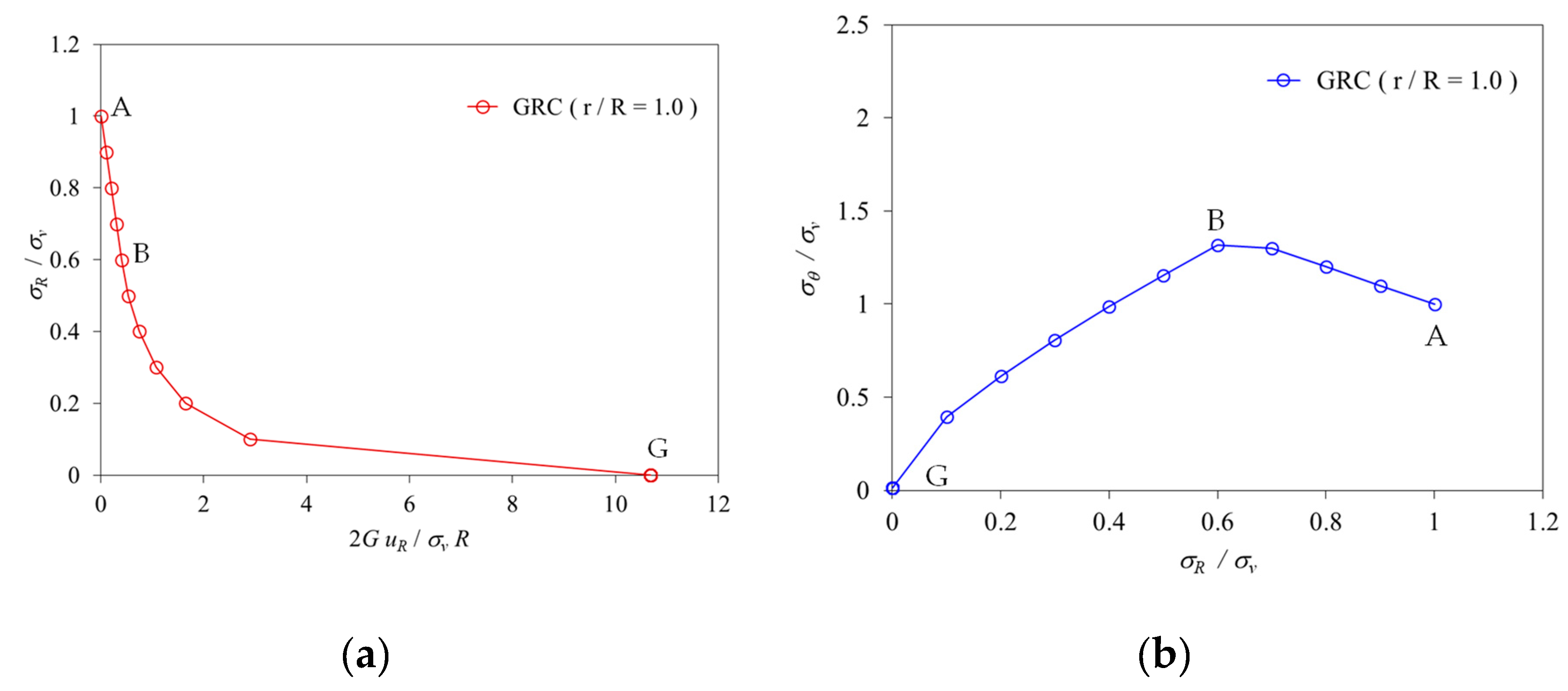
The behavior of rock mass at the intrados of the tunnel is altered by the advancing excavation of the tunnel face and may be interpreted by the ground reaction curve and the stress path at any point of the intrados of the tunnel. In this paper, the dimensionless radial displacement (2Gur/Rσv), and radial and tangential stresses normalized by the vertical stress (σv), in the elastic region and plastic region are plotted in Fig 8-15.
As shown in Figure 8, the results obtained by the EAM using the data of Case I [41] indicate that the behavior of the hard rock presents linear elasticity in the ground reaction curve and the stress path. The calculated result is in agreement with the theoretical value that the dimensionless radial displacement is equal to 1.0 (Figure 8(a)), and the dimensionless radial and tangential stresses are equal to 0 and 2, respectively (Figure 8(b)).
In addition, the characteristic behavior of the soft rocks (Case II~IV) is described in Figure 9, Figure 10 and Figure 11. It indicates that the behavior of the soft rocks presents the non-linear elastic-perfectly-plasticity in the ground reaction curve. The interface between the elastic region (line AB) and the plastic region (curve BC) is represented by point B. For the stress path, the Hoek-Brown failure criterion is obviously shown the characteristic non-linearity by the curve BG in Figures 9(b)–11(b).
According to the analysis results between EAM and the listed articles (shown in Table 2), the percentage error of the radial displacement is from 0.5% to 3.51% for the hard and soft rocks. The results obtained by the calculation of EAM in this study show a consistent trend with the data in the references.
5.2. Distribution of stress/displacement on the cross-section of the tunnel
Around a circular tunnel excavation in an isotropic stress state, one is interested in the stress/displacement distribution over the tunnel cross-section. According to the stress distribution results of the tunnel, the following five stress states can be used to describe and verify the stress changes caused by the advancing excavation of the tunnel face: (1) When λ = 0 (), it indicates that the stresses are in the initial stress state as shown the horizontal line on the right side in Figure 12(a); (2) When 0 (), it describes that the stresses are in the elastic region, and the radial and tangential stresses increase with the increase of the confinement loss, and both stresses are symmetrically separated along the horizontal axis (r/R); (3) When (), the plastic radius appears and stresses are at the elastic-plastic interface. The radial stress begins to change the curvature, and the tangential stress attains the maximum value as shown in Figures 13a–15a; (4) When (), it indicates that the stresses are in the plastic region, and this leads to both the radial stress and tangential stress being decreased steeply; and (5) Until (), the radial stress becomes zero and the tangential stress is equal to the coefficient proposed by the Hoek-Brown failure criterion.
Figure 12.
Results obtained by the EAM using the data of Case I [41], (a) stress distribution, and (b) radial displacement distribution on the cross-section of the tunnel (Rp/R = 1.0).
Figure 12.
Results obtained by the EAM using the data of Case I [41], (a) stress distribution, and (b) radial displacement distribution on the cross-section of the tunnel (Rp/R = 1.0).
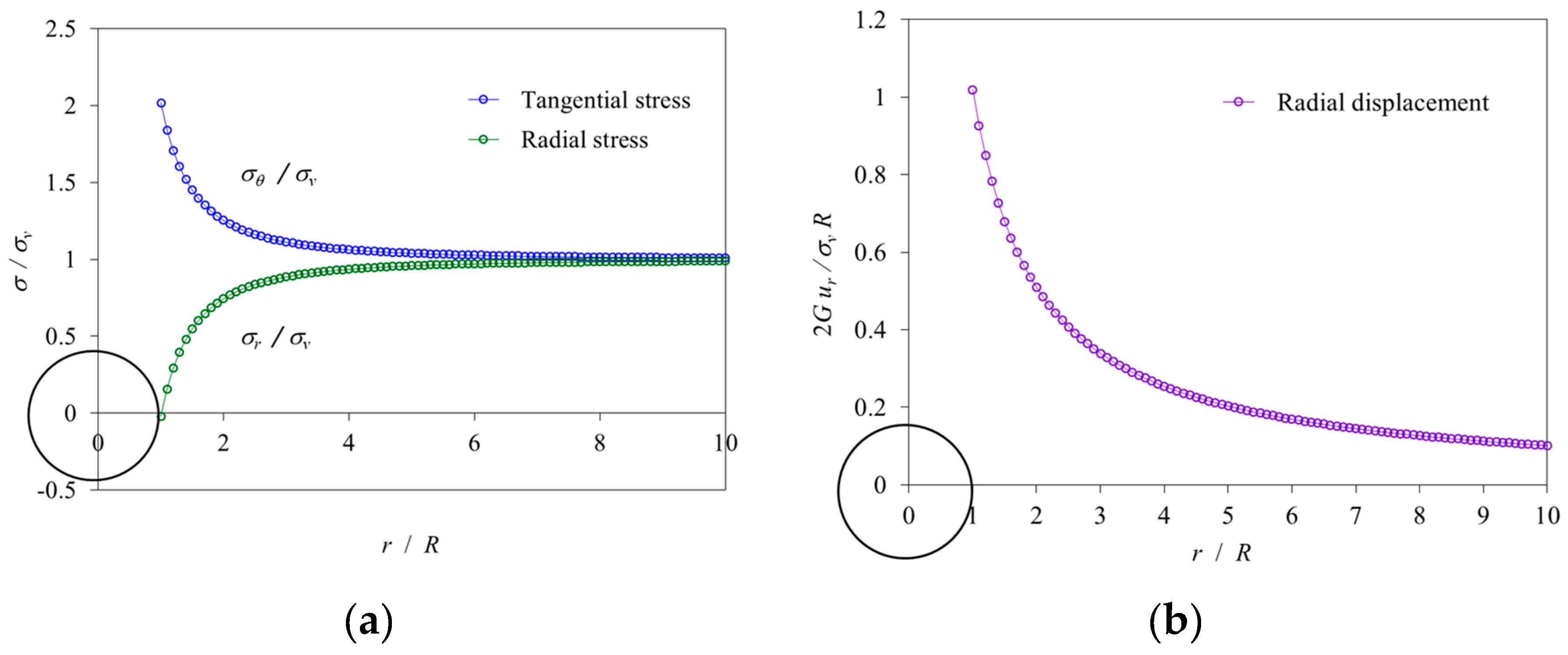
Figure 13.
Results obtained by the EAM using the data of Case II [41], (a) stress distribution, and (b) radial displacement distribution on the cross-section of the tunnel (Rp/R = 1.65).
Figure 13.
Results obtained by the EAM using the data of Case II [41], (a) stress distribution, and (b) radial displacement distribution on the cross-section of the tunnel (Rp/R = 1.65).
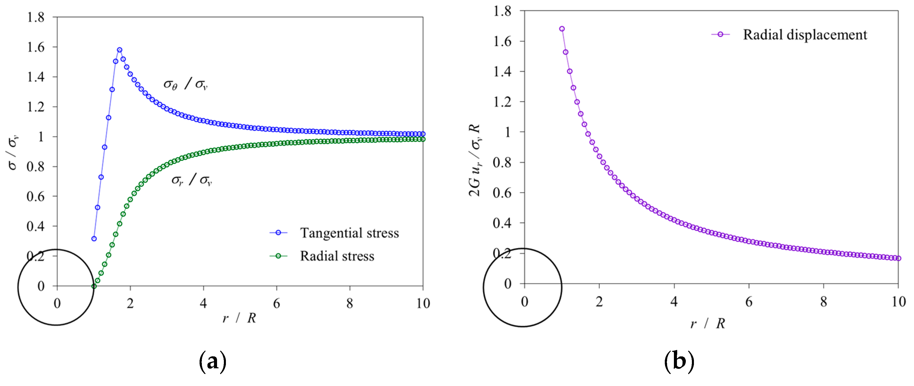
Figure 14.
Results obtained by the EAM using the data of Case III [42], (a) stress distribution, and (b) radial displacement distribution on the cross-section of the tunnel (Rp/R = 2. 59).
Figure 14.
Results obtained by the EAM using the data of Case III [42], (a) stress distribution, and (b) radial displacement distribution on the cross-section of the tunnel (Rp/R = 2. 59).
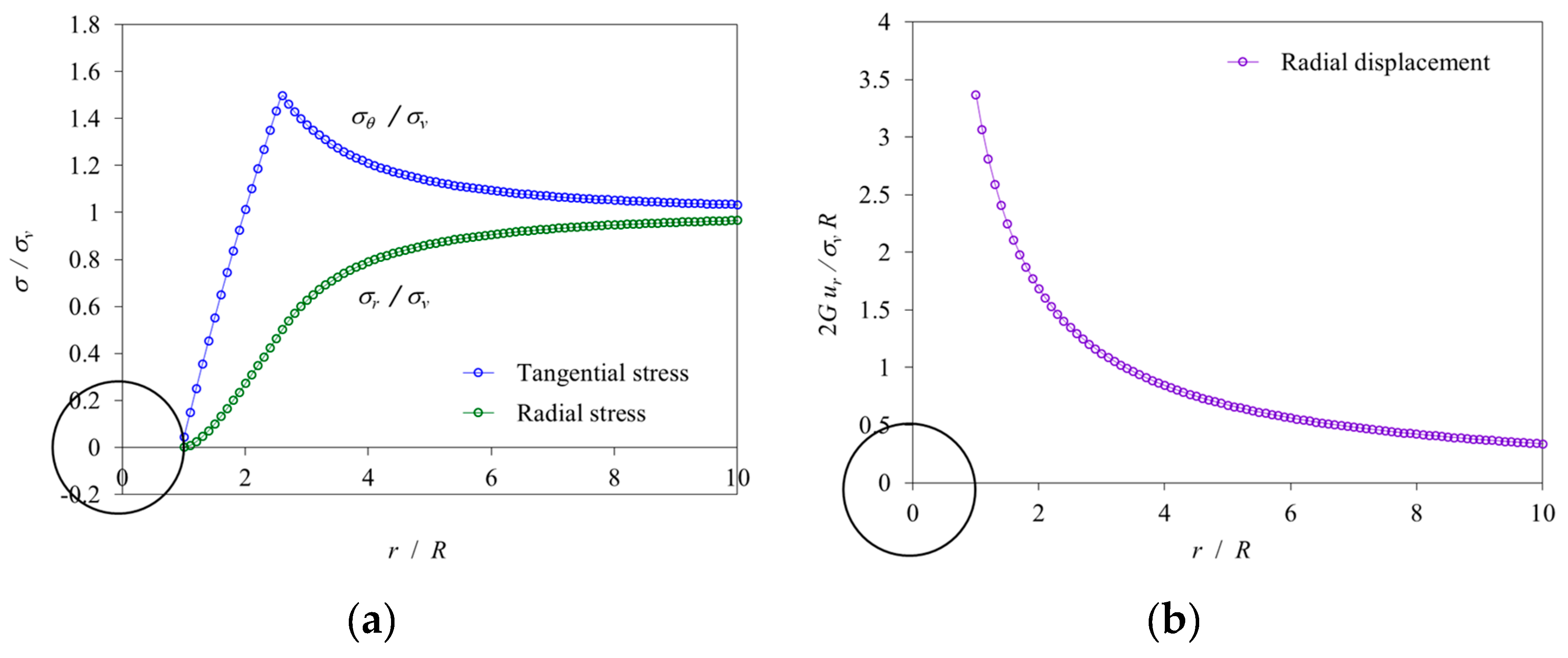
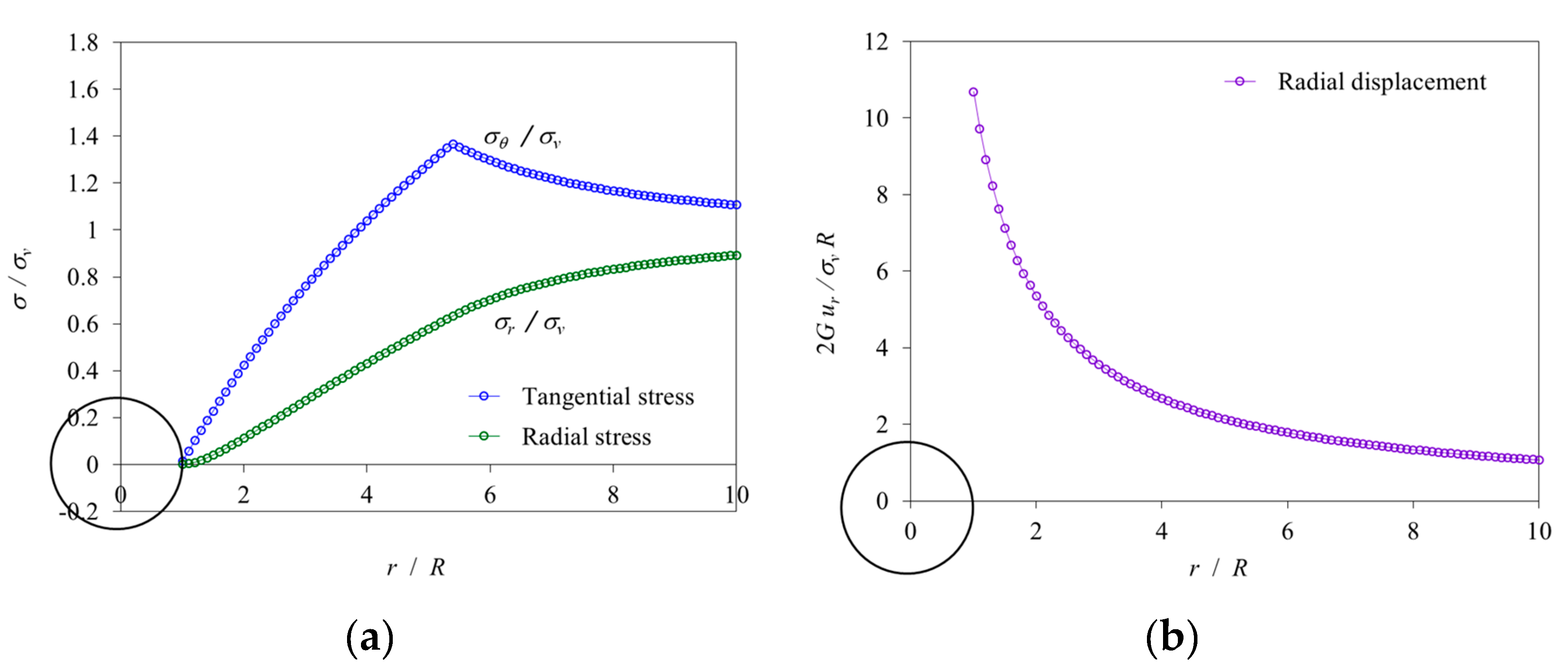
Figure 15.
Results obtained by the EAM using the data of Case IV [42], (a) stress distribution, and (b) radial displacement distribution on the cross-section of the tunnel (Rp/R =5.38).
Figure 15.
Results obtained by the EAM using the data of Case IV [42], (a) stress distribution, and (b) radial displacement distribution on the cross-section of the tunnel (Rp/R =5.38).
As shown in Table 2, according to the analysis results between EAM and the listed articles, the percentage error of the plastic zone radius is from 1.67% to 2.28% for the soft rocks. However, the plastic radius obtained in Case III shows a large error value.
6. Conclusions
Through the rigorous theoretical analysis (CCM) of nonlinear mechanical behavior (Hoek-Brown model) caused by tunnel advancing excavation, the derivation of mechanical partial differential equations, the establishment and practice of incremental calculation program (EAM), and the comparison of published results, the following conclusions can be drawn:
- (1)
- A theoretically consistent closed-form analytical solution was derived for the elastic-perfectly-plastic analysis of a circular tunnel in a rock mass governed by the Hoek-Brown non-linear failure criterion and subject to isotropic in-situ stress.
- (2)
- The confinement loss in the elastic limit situation is a function of the peak strength parameters of the rock mass, and the initial vertical stress.
- (3)
- The plastic radius is also a function of the peak strength parameters of the rock mass, the confinement loss in the elastic limit situation, and is also dependent on the confinement loss. As the confinement loss increases, the plastic radius increases and consequently leads to both the radial stress and tangential stress being decreased, even as the radial displacement increases simultaneously in the plastic region.
- (4)
- The incremental procedure of the explicit analysis method (EAM) is particularly proposed to deal with using the confinement loss as an incremental step to simulate the effect of advancing excavation of the tunnel face, calculating the stresses and displacements in each step, and drawing the ground reaction curve, the stress path at the intrados of the tunnel, and the distribution of stresses/displacements on the cross-sections of the tunnel.
- (5)
- The agreement between the published results and the proposed closed-form solutions with the explicit procedure was found to be excellent in elastic-perfectly-plastic media.
- (6)
- The variation of stresses due to the advancing excavation of the tunnel face can be mainly interpreted by the stress gradient which is a difference between far-field stress and near-field stress around a tunnel and can be obtained employing the hypothesis of increments in the numerical analysis. The increment of stresses can be considered with the confinement loss as a fraction of the stress gradient.
- (7)
- The proposed incremental procedure method can deal with the effect of the non-linear failure criterion of the rock mass, not only it can be a useful tool for the analysis of a circular tunnel in an isotropic stress state, but it perhaps may be applied to the simulation of the behavior of the tunnel under the condition of an anisotropic stress in the next stage study.
Author Contributions
Methodology, Supervision, Writing—original draft, Y.-L.L.; Formula derivation, Verification, C.-H. M., and C.-M.L.; Software programming, Computation, C.-M.L. All authors have read and agreed to the published version of the manuscript.
Conflicts of Interest
The authors declare no conflict of interest.
References
- Panet, M. Calcul du souténement des tunnels à section circulaire par la method convergence-confinement avec un champ de contraintes initiales anisotrope. Tunnels et Ouvrages Souterrains 1986, 77, 228–232.
- Panet, M. Le Calcul des Tunnels par la Méthode de Convergence-Confinement; Presses de l’Ecole Nationale des Ponts et Chaussées: Paris, France, 1995. [Google Scholar]
- Panet, M. Recommendations on the convergence-confinement method. Association Française des Tunnels et de l'Espace Souterrain 2001, 1–11. Available online: https://tunnel.ita-aites.org/media/k2/attachments/public/Convergence-confinement%20AFTES.pdf.
- Panet, M.; Sulem, J. Convergence-Confinement Method for Tunnel Design; Springer: Berlin, Germany, 2022. [Google Scholar] [CrossRef]
- Lee, Y.L.; Hsu, W.K.; Lee, C.M.; Xin, Y.X.; Zhou, B.Y. Direct calculation method for the analysis of non-linear behavior of ground-support interaction of circular tunnel using convergence–confinement approach. Geotech Geol Eng 2021, 39, 973–990. [CrossRef]
- Lee, Y.L.; Hsu, W.K.; Chou, P.Y.; Hsieh, P.W.; Ma; C.H.; Kao; W.C. Verification and comparison of direct calculation method for the analysis of ground-support interaction of a circular tunnel excavation. Applied Sciences 2022, 12, 1–13. [CrossRef]
- Oreste, P.P. Analysis of structural interaction in tunnels using the convergence-confinement approach. Tunnell Undergr Space Technol 2003, 18, 347–363. [CrossRef]
- Oreste, P. The convergence–confinement method: roles and limits in modern geomechanical tunnel design. Am J Appl Sci 2009, 6, 757–771. [CrossRef]
- Cui, L.; Zheng, J.; Zhang, R.; Lai, H. A numerical procedure for the fictitious support pressure in the application of the convergence-confinement method for circular tunnel design. Int J Rock Mech Min Sci 2015, 78, 336–349. [CrossRef]
- Brown, E.; Bray, J.; Ladanyi, B.; Hoek, E. Ground response curves for rock tunnels. J Geotech Eng ASCE 1983, 109, 15–39. [CrossRef]
- Brady, B.; Brown, E. Rock Mechanics for Underground Mining; Chapman & Hall: London, United Kingdom, 1993. [Google Scholar]
- Wang, Y. Ground response of a circular tunnel in poorly consolidated rock. J Geotech Eng ASCE 1996, 122, 703–708. [CrossRef]
- Guan, Z.; Jiang, Y.; Tanabasi, Y. Ground reaction analyses in conventional tunnelling excavation. Tunnell Undergr Space Technol 2007, 22, 230–237. [CrossRef]
- Alejano, L.R.; Rodriguez-Dono, A.; Alonso, E.; Fdez.-Manín, G. Ground reaction curves for tunnels excavated in different quality rock masses showing several types of post-failure behavior. Tunnell Undergr Space Technol 2011, 24, 689–705. [CrossRef]
- Mousivand, M.; Maleki, M.; Nekooei, M.; Msnsoori, M.R. Application of convergence-confinement method in analysis of shallow non-circular tunnels. Geotech Geol Eng 2017, 35, 1185–1198. [Google Scholar] [CrossRef]
- Rocksupport. Rock support interaction and deformation analysis for tunnels in weak rock; Tutorial Manual of Rocscience Inc, 2004; pp. 1–76. [Google Scholar]
- Rodríguez, R.; Díaz-Aguado, M.B. Deduction and use of an analytical expression for the characteristic curve of a support based on yielding steel ribs. Tunnell Undergr Space Technol 2013, 33, 159–170. [Google Scholar] [CrossRef]
- Cui, L.; Zheng, J.; Zhang, R.; Lai, H. A numerical procedure for the fictitious support pressure in the application of the convergence-confinement method for circular tunnel design. Int J Rock Mech Min Sci 2015, 78, 336–349. [Google Scholar] [CrossRef]
- Carranza-Torres, C.; Engen, M. The support characteristic curve for blocked steel sets in the convergence-confinement method of tunnel support design. Tunnell Undergr Space Technol 2017, 69, 233–244. [Google Scholar] [CrossRef]
- Oke, J.; Vlachopoulos, N.; Diederichs, M. Improvement to the convergence-confinement method: inclusion of support installation proximity and stiffness. Rock Mech Rock Eng 2018, 51, 1495–1519. [Google Scholar] [CrossRef]
- Vlachopoulos, N.; Diederichs, M. Improvement to the convergence-confinement method: Inclusion of support installation proximity and stiffness. Rock Mech Rock Eng 2018, 51, 1495–1519. [CrossRef]
- De La Fuente, M.; Taherzadeh, R.; Sulem, J.; Nguyen, X.S.; Subrin, D. Applicability of the convergence-confinement method to full-face excavation of circular tunnels with stiff support system. Rock Mech Rock Eng 2019, 52, 2361–2376. [Google Scholar] [CrossRef]
- Lee, Y.L. Explicit analysis for the ground-support interaction of circular tunnel excavation in anisotropic stress fields. J Chinese Inst Eng 2020, 43, 13–26. [Google Scholar] [CrossRef]
- Bernaud, D.; Rosset, G. The new implicit method for tunnel analysis. Int J Num Analyt Meth Geomech 1996, 20, 673–690. [CrossRef]
- Humbert, P.; Dubouchet, A.; Fezans, G.; Remaud, D. CESAR-LCPC, un progiciel de calcul dédié au génie civil. Bulletin des Laboratoires des ponts et Chaussées 2005, 256, 7–37. Available online: https://www.ifsttar.fr/collections/BLPCpdfs/blpc_256-257_7-37.pdf.
- González-Nicieza, C.; Álvarez-Vigil, A.E.; Menéndez-Díaz, A.; González-Palacio, C. Influence of the depth and shape of a tunnel in the application of the convergence-confinement method. Tunnell Undergr Space Technol 2008, 23, 25–37. [CrossRef]
- Vlachopoulos, N.; Diederichs, M. Improved longitudinal displacement profiles for convergence confinement analysis of deep tunnels. Rock Mech Rock Eng 2009, 42, 131–146. [CrossRef]
- Mousivand, M.; Maleki, M. Constitutive models and determining methods effects on application of Convergence-Confinement method in underground excavation. Geotech Geolog Eng 2017, 36, 1707–1722. [CrossRef]
- Zhao, K.; Bonini, M.; Debernardi, D.; Janutolo, M.; Barla, G.; Chen, G. Computational modelling of the mechanised excavation of deep tunnels in weak rock. Computers Geotechics 2015, 66, 158–171. [CrossRef]
- Mousivand, M.; Maleki, M.; Nekooei, M.; Msnsoori, M.R. Application of Convergence-Confinement method in analysis of shallow non-circular tunnels. Geotech Geolog Eng 2018, 35, 1185–1198. [CrossRef]
- Hoek, E.; Brown, E.T. Empirical strength criterion for rock masses. J Geotech Eng ASCE 1980, 106(9), 1013–1035. [Google Scholar] [CrossRef]
- Hoek, E.; Brown, E.T. Underground Excavations in Rock; London, Instn Min. Metal., 1980. [Google Scholar]
- Hoek, E.; Carranza-Torres, C.; Corkum, B. Hoek–Brown failure criterion – 2002 edition, Proc NARMS-Tac 2020, 1, 267–273.
- Carranza-Torres, C.; Fairhurst, C. The elasto-plastic response of underground excavations in rock masses that satisfy the Hoek–Brown failure criterion. Int J Rock Mech Min Sci 1996, 36, 777–809. [CrossRef]
- Carranza-Torres, C.; Fairhurst, C. Application of the convergence-confinement method of tunnel design to rock masses that satisfy the Hoek–Brown failure criterion. Tunnell Undergr Space Technol 2000, 15, 187–213. [CrossRef]
- Carranza-Torres, C. Elasto-plastic solution of tunnel problems using the generalized form of the Hoek-Brown failure criterion. Int J Rock Mech Min Sci 2004, 41(3), 480–491. [Google Scholar] [CrossRef]
- Sharan, S.K. Exact and approximate solutions for displacements around circular openings in elastic-brittle plastic Hoek-Brown rock. Int J Rock Mech Min Sci 2005, 42, 542–549. [CrossRef]
- Park, K.H.; Kim, Y.J. Analytical solution for a circular opening in an elastic–brittle–plastic rock. Int J Rock Mech Min Sci 2006, 43, 616–622. [CrossRef]
- Serrano A.; Olalla C.; Reig I. Convergence of circular tunnels in elastoplastic rock masses with non-linear failure criteria and non-associated flow laws. Int J Rock Mech Min Sci 2011, 48, 878–887. [CrossRef]
- Shen, B.; Barton, N. The disturbed zone around tunnels in jointed rock masses. Int J Rock Mech Min Sci 1997, 34, 117–125. [CrossRef]
- Sharan, S.K. Elastic–brittle–plastic analysis of circular openings in Hoek–Brown media. Int J Rock Mech Min Sci 2003, 40, 817–824. [CrossRef]
- Rocksupport. Rock Support Interaction and Deformation Analysis for Tunnels in Weak Rock; Tutorial Manual of Rocscience Inc.; Rocscience Inc.: Toronto, ON, USA, 2004; pp. 1–76. [Google Scholar]
Figure 1.
Schematic illustration of the ground-support interaction in the analysis of the convergence-confinement method (CCM) including the ground reaction curve (GRC), the support confining curve (SCC), and the confinement loss curve (CLC).
Figure 1.
Schematic illustration of the ground-support interaction in the analysis of the convergence-confinement method (CCM) including the ground reaction curve (GRC), the support confining curve (SCC), and the confinement loss curve (CLC).
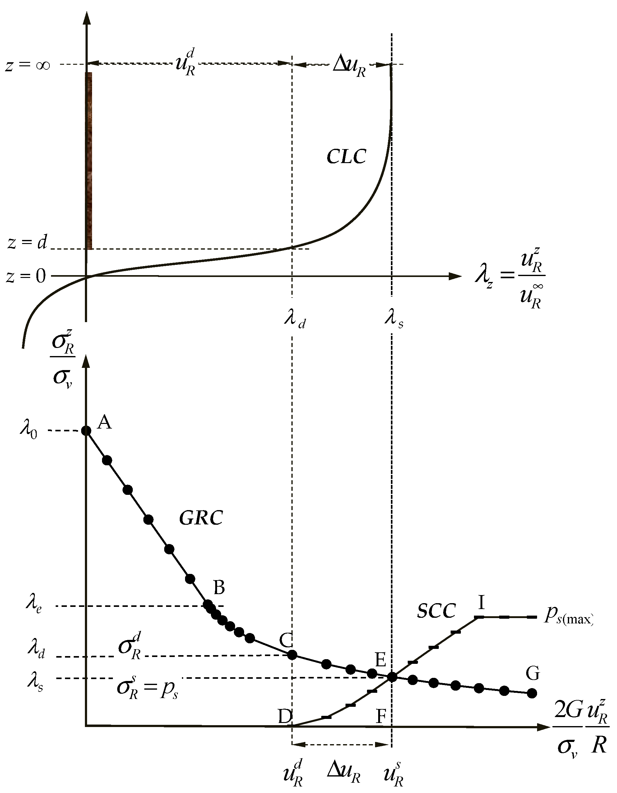
Figure 2.
Schematic illustration of the confinement loss curve (CLC) with support (solid line) or without support (dotted line).
Figure 2.
Schematic illustration of the confinement loss curve (CLC) with support (solid line) or without support (dotted line).
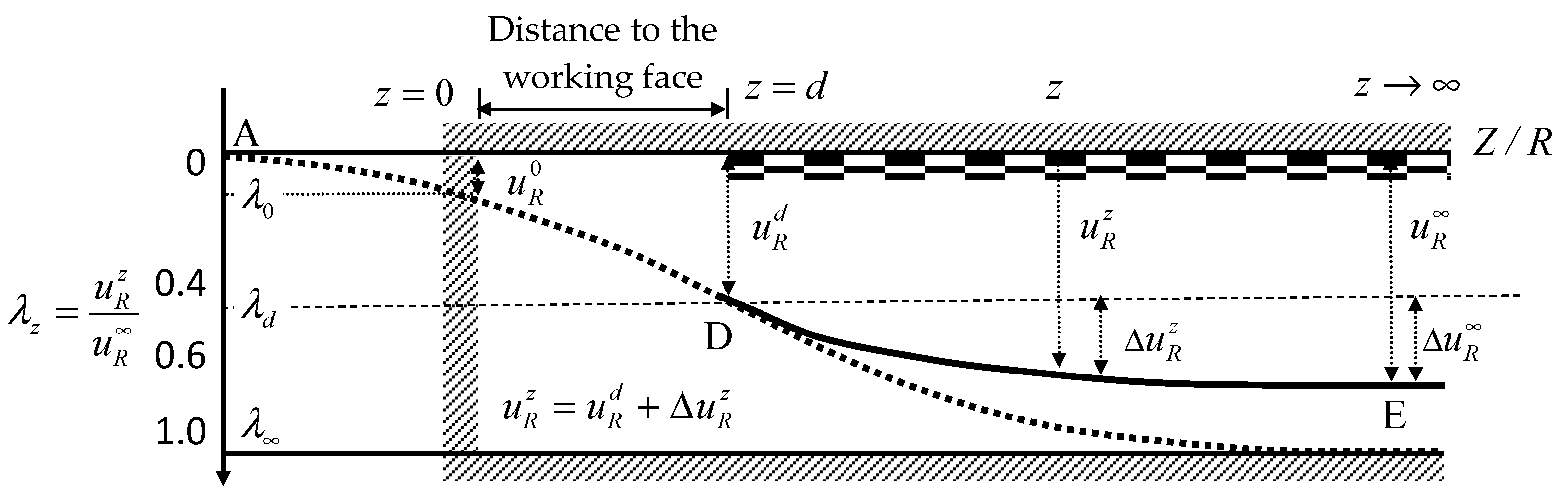
Figure 3.
Stress variation around the tunnel from far-field to near-field in an isotropic stress field.
Figure 3.
Stress variation around the tunnel from far-field to near-field in an isotropic stress field.
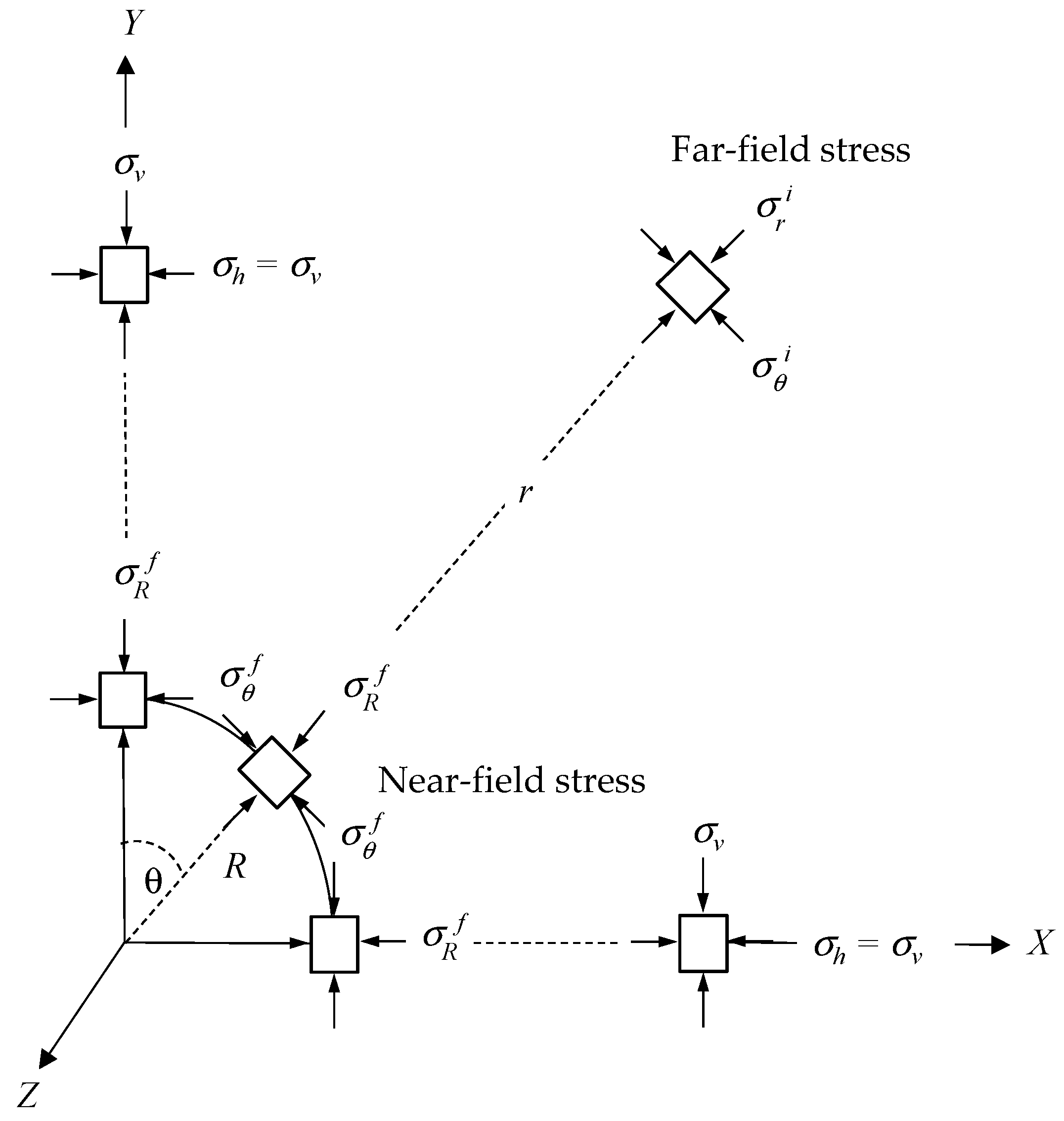
Figure 4.
Schematic illustration of linear (Mohr-Coulomb) and non-linear (Hoek-Brown) failure criteria.
Figure 4.
Schematic illustration of linear (Mohr-Coulomb) and non-linear (Hoek-Brown) failure criteria.
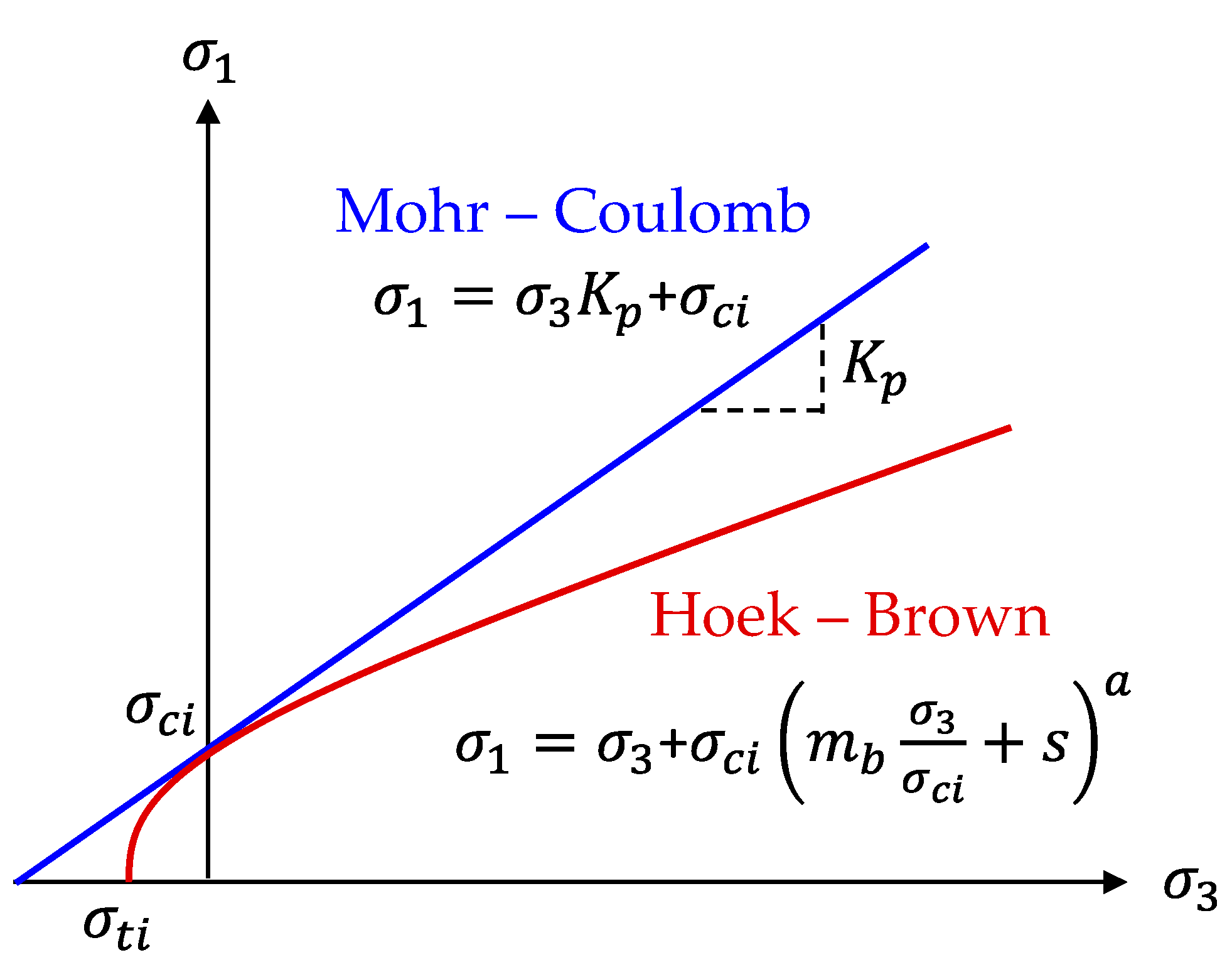
Figure 5.
Plastic potential function with non-associated flow rule
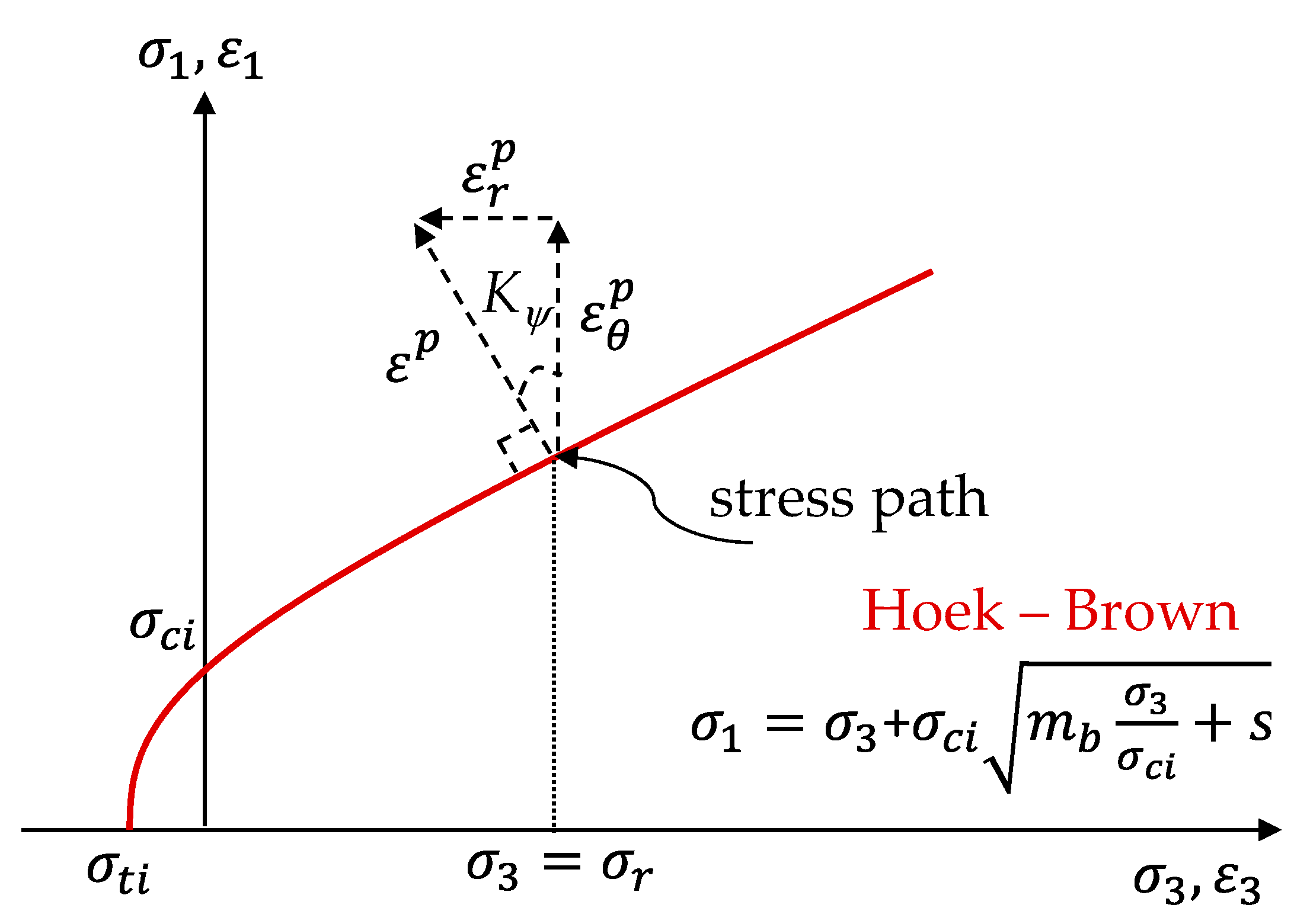
Figure 6.
Calculation spreadsheet presented by the explicit algorithm process (EAM).

Figure 7.
Drawing results presented by the explicit algorithm process (EAM).
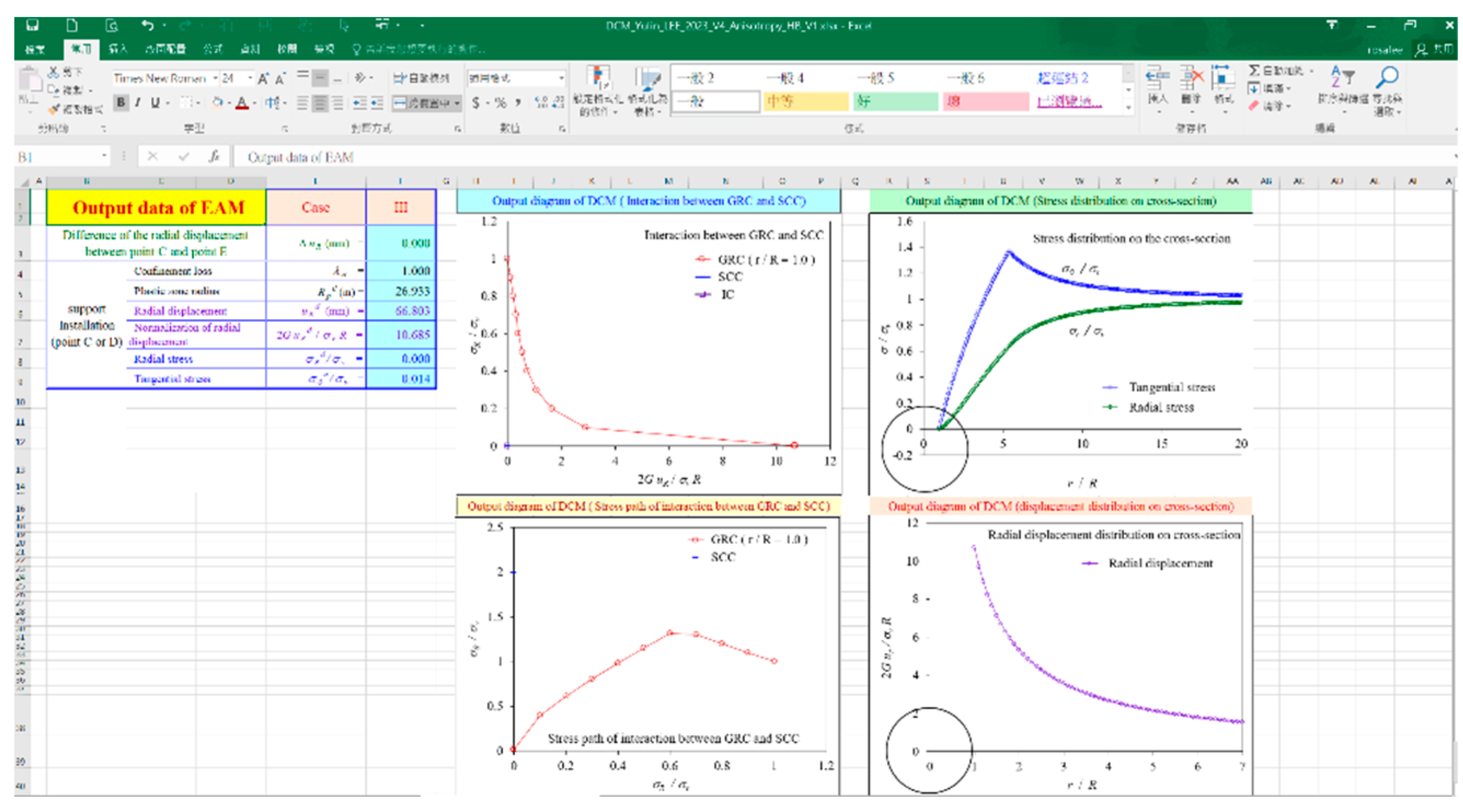
Figure 8.
Results obtained by the EAM using the data of Case I [41], (a) the ground reaction curve, and (b) the stress path at the intrados of the tunnel (Rp/R = 1.0).
Figure 8.
Results obtained by the EAM using the data of Case I [41], (a) the ground reaction curve, and (b) the stress path at the intrados of the tunnel (Rp/R = 1.0).
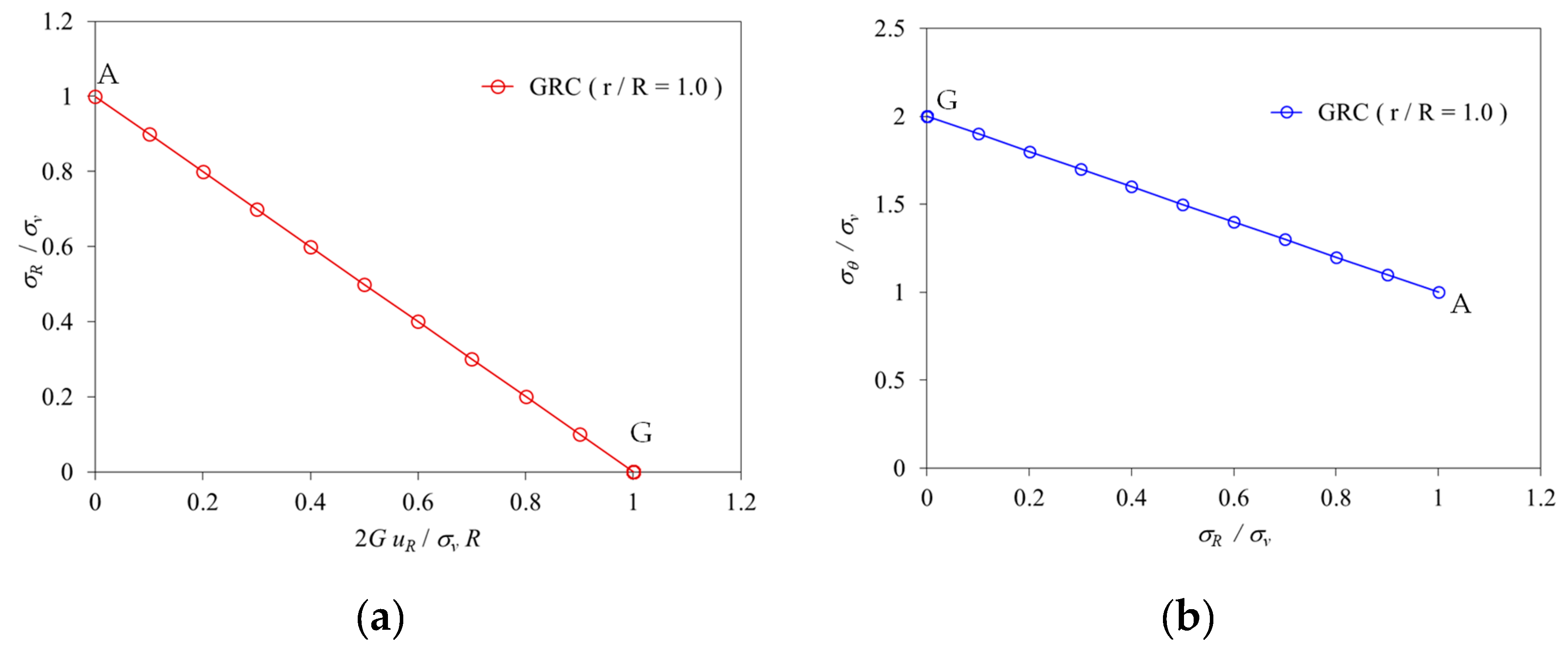
Figure 9.
Results obtained by the EAM using the data of Case II [41], (a) the ground reaction curve, and (b) the stress path at the intrados of the tunnel (Rp/R = 1.65).
Figure 9.
Results obtained by the EAM using the data of Case II [41], (a) the ground reaction curve, and (b) the stress path at the intrados of the tunnel (Rp/R = 1.65).
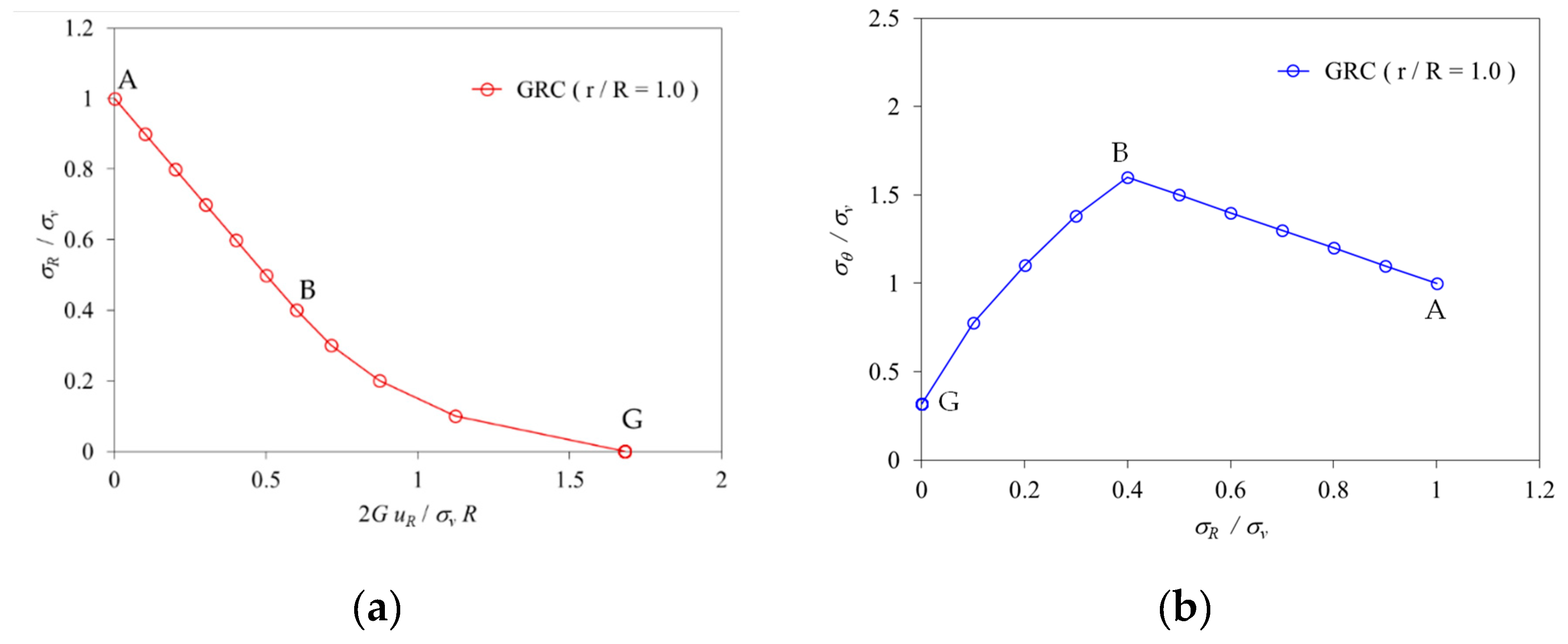
Figure 10.
Results obtained by the EAM using the data of Case III [42], (a) the ground reaction curve, and (b) the stress path at the intrados of the tunnel (Rp/R = 2.59).
Figure 10.
Results obtained by the EAM using the data of Case III [42], (a) the ground reaction curve, and (b) the stress path at the intrados of the tunnel (Rp/R = 2.59).
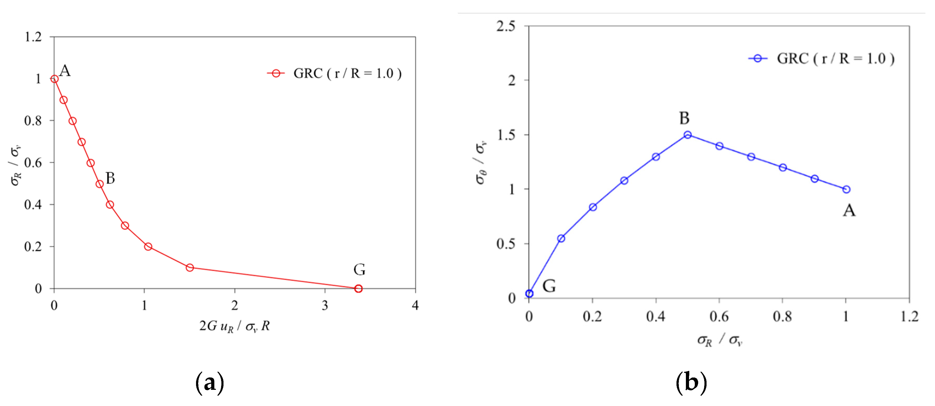
Figure 11.
Results obtained by the EAM using the data of Case IV [42], (a) the ground reaction curve, and (b) the stress path at the intrados of the tunnel (Rp/R = 5.38).
Figure 11.
Results obtained by the EAM using the data of Case IV [42], (a) the ground reaction curve, and (b) the stress path at the intrados of the tunnel (Rp/R = 5.38).

| Reference | Sharan (2003) [41] | Rocksupport (2004) [42] | ||
| Parameter | Case I | Case II | Case III | Case IV |
| E (MPa) | 40,000. | 5,500. | 3,530. | 2100. |
| v | 0.20 | 0.25 | 0.3 | 0.3 |
| mi | 7.5 | 7.5 | 10 | 12 |
| GIS | 100 | 80 | 22 | 17 |
| D | 0 | 0 | 0 | 0 |
| σci (MPa) | 300. | 30. | 5. | 4. |
| Kψ | 0. | 0. | 0. | 0. |
| σv (MPa) | 108. | 30. | 1.62 | 2.02 |
| R (m) | 4.0 | 5.0 | 6.0 | 5.0 |
| Published studies |
Radial Displacement, uR (mm) | Plastic Zone Radius, Rp (m) | EAM Radial Displacement, uR (mm) (Error* %) |
EAM Plastic Zone Radius, Rp (m) (Error* %) |
| Case I | 12.52 | N/A | 12.96 (3.51 %) | N/A |
| Case II | 56.05 | 8.12 | 57.30 (2.23 %) | 8.25 (1.67 %) |
| Case III | 12.0 | 13.77 | 12.06 (0.5 %) | 15.55 (12.93 %) |
| Case IV | 65.5 | 26.30 | 66.80 (1.98 %) | 26.9 (2.28 %) |
Disclaimer/Publisher’s Note: The statements, opinions and data contained in all publications are solely those of the individual author(s) and contributor(s) and not of MDPI and/or the editor(s). MDPI and/or the editor(s) disclaim responsibility for any injury to people or property resulting from any ideas, methods, instructions or products referred to in the content. |
© 2023 by the authors. Licensee MDPI, Basel, Switzerland. This article is an open access article distributed under the terms and conditions of the Creative Commons Attribution (CC BY) license (http://creativecommons.org/licenses/by/4.0/).
Copyright: This open access article is published under a Creative Commons CC BY 4.0 license, which permit the free download, distribution, and reuse, provided that the author and preprint are cited in any reuse.


