
Submitted:
09 June 2023
Posted:
12 June 2023
You are already at the latest version
Abstract
The paper presents the conceptualization and realization of a novel platform for additive manu-facturing, an industrial robot arm-based system for additive manufacturing applications. Tradi-tional 3D printers, especially those employing fused deposition modelling (FDM) processes, are restricted to depositing material in a single toolpath plane (e.g. x-y plane). The focus of this study was to explore the feasibility of integrating commercial off the shelf (COTS) additive manufac-turing technologies with a six degree of freedom industrial robot arm to yield a 3D additive manufacturing system with the capability to perform free-form six degree of freedom fused deposition modelling. The present paper presents the development of a platform from stage 0, i.e. materials to its use, and finally a printed product with the developed extruder.
Keywords:
additive manufacturing applications
; 3D printing platform for additive manufacturing
; FDM
; robot arm
1. Introduction
The present research will present the possibility of using an extruder placed on the robot to print FDM polymers. Fused Deposition Modelling (FDM) is a process that uses 3D printer extruder nozzles. The process is achieved by extruding a material through a nozzle to form an object. The FDM process uses the motion of the portal system to control where the material is deposited in a two-dimensional plane.
Depositing these planes vertically is what creates the 3D printed part. The extruded material must be heated to flow through the extruder. FDM is a very used method for conventional 3D printing due to its cheap and friendly platform and open-source movement. If is a situation that needs to generate multi-plane motion to increase layering capability, a serial link manipulator or robot arm can be used as a platform.
The industrial robot arms are a very used platform used in all the manufacturing industries (automotive, naval, civil engineering). The flexibility of their movement is what determinates to be used in so many different applications including welding, assembly, pick and place, product inspection, testing and other applications. Usually, the industrial robot arm has freedom of movement depending on the number and types of joints that have been connected. The main advantage of industrial robot arms is their relatively high degree of freedom (DoF). Because of DoF, a serial arm with 6 DoF can perform multi-planar movements in their working environment compared to the conventional machine-type 3D printer portal, run into 3 DoF that are only capable of making planar layering [1,2,6].
Developing a robot arm system for additive manufacturing (AM) applications involves integrating robotic technology with 3D printing capabilities. This combination allows for the automated production of complex geometries and the deposition of material layer by layer. Some key steps involved in developing such a system:
Requirements Analysis: Determine the specific requirements of your additive manufacturing application. Consider factors such as the desired build volume, material compatibility, printing speed, accuracy, and complexity of the parts to be printed.
Robotic Arm Selection: Choose a suitable robotic arm based on the application requirements. Consider factors like payload capacity, reach, precision, and the number of degrees of freedom. Collaborative robots (cobots) are often preferred due to their flexibility and ability to work alongside humans.
End-Effector Selection: Select an appropriate end-effector or toolhead for the robotic arm that is capable of performing additive manufacturing tasks. This may involve choosing a 3D printing extruder or other specialized equipment required for the specific AM process, such as laser sintering or powder deposition.
System Integration: Integrate the robotic arm with the AM toolhead. This involves developing or customizing the necessary hardware and software interfaces to ensure seamless communication and control between the robotic arm and the 3D printing system. Collaborative robots often have built-in safety features and user-friendly programming interfaces, simplifying integration efforts.
Motion Planning and Path Generation: Develop algorithms for motion planning and path generation to enable the robotic arm to move precisely and deposit material accurately during the 3D printing process. These algorithms should optimize the toolpath for efficient printing while considering factors such as support structures, layer bonding, and overall print quality.
Material Handling and Supply: Implement a system for managing the supply of additive manufacturing materials, whether it's filament, powder, or liquid resin. This may include automated material loading, unloading, and monitoring mechanisms to ensure a continuous printing process.
Process Monitoring and Quality Control: Integrate sensors and monitoring systems to track the printing process in real-time. This can include monitoring factors such as temperature, material flow rate, deposition quality, and potential defects. Implement quality control mechanisms to detect and address any issues during the printing process.
Safety Considerations: Ensure proper safety measures are in place to protect operators and equipment. Collaborative robots should have safety features like force sensing, collision detection, and emergency stop functionality. Implement appropriate safeguards to prevent accidents and mitigate risks associated with the AM process.
Testing and Optimization: Conduct thorough testing of the robotic arm system for additive manufacturing applications. Optimize the system by fine-tuning parameters, improving accuracy, and addressing any performance issues that arise during testing.
Scalability and Flexibility: Design the system with scalability and flexibility in mind to accommodate future needs and potential changes in the additive manufacturing process. Consider the possibility of integrating multiple robotic arms or expanding the system for larger-scale production.
Throughout the development process, it's essential to collaborate with experts in robotics, additive manufacturing, and automation to ensure the successful integration and optimization of the robot arm system for additive manufacturing applications. It's important to note that the specific details of developing a robot arm system for additive manufacturing can vary depending on the chosen technique (e.g., FDM, SLA, SLS) and the desired application. It is recommended to consult with experts in both robotics and additive manufacturing to ensure the successful development and integration of such a system [7,8] .
When we think of a robot arm system for additive manufacturing applications, it is important to consider various standards and guidelines to ensure safety, quality, and compatibility. Some are listed below:
- -
- ISO 10218: This international standard specifies the safety requirements for industrial robots. It covers areas such as robot system design, integration, and operation, including considerations for collaborative robots (cobots).
- -
- ISO/ASTM 52900: This standard provides guidelines for additive manufacturing processes. It covers aspects such as terminology, process control, design, post-processing, and quality assurance for additive manufacturing systems.
- -
- ASTM E2500: This standard outlines the requirements for the qualification, verification, and validation of robotic systems. It includes considerations for system design, installation, commissioning, and operational performance.
- -
- ISO 13849: This standard addresses the safety of machinery and provides guidelines for the design and implementation of safety-related control systems. It specifies requirements for the functional safety of robotic systems, including risk assessment and performance levels.
- -
- ANSI/RIA R15.06: This standard is specific to industrial robot safety in the United States. It provides guidelines for system integration, safeguarding, and operational practices, including considerations for collaborative robot systems.
- -
- ISO 12100: This standard focuses on general principles of machinery safety, including risk assessment and risk reduction. It provides guidance on hazard identification, risk assessment, and risk reduction measures for machinery, including robotic systems.
When designing a robot arm system for additive manufacturing applications, it's crucial to consult these standards and any other applicable local regulations to ensure compliance, safety, and quality. Additionally, it's recommended to involve experts in robotics, additive manufacturing, and safety engineering to address specific requirements and challenges in your application.
2. Materials
The Materials used was PETG. PETG (Polyethylene Terephthalate Glycol) is a thermoplastic material that has become increasingly popular in various industries due to its unique properties. Here are some of its principal properties:
Transparency: PETG is transparent, allowing for clear visibility through the material. This property makes it a popular choice in industries such as packaging and signage.
Impact Resistance: PETG has excellent impact resistance, making it less likely to crack or break when subjected to sudden or high-impact forces. This property makes it a popular choice in industries such as transportation, where materials are exposed to constant vibrations and impacts.
Chemical Resistance: PETG is resistant to many chemicals, including acids, alkalis, and alcohols. This property makes it a popular choice in industries such as medical and laboratory, where materials must withstand exposure to various chemicals.
Flexibility: PETG is flexible and can be easily formed into various shapes and sizes. This property makes it a popular choice in industries such as packaging, where materials must be flexible and able to conform to different shapes and sizes.
Recyclability: PETG is highly recyclable, making it an environmentally friendly option. It can be recycled into various products such as clothing, carpet fibers, and packaging materials.
Overall, the combination of these properties makes PETG a versatile material with a wide range of applications in various industries. PETG (Polyethylene Terephthalate Glycol) is a thermoplastic material that has become increasingly popular in the FDM (Fused Deposition Modeling) 3D printing process. PETG offers a number of important advantages over other commonly used 3D printing materials like PLA and ABS.
One of the key advantages of PETG is its excellent layer adhesion, which means that the layers of the 3D print stick together well and do not easily separate or delaminate. This makes PETG an ideal material for creating strong and durable parts that can withstand stress and strain.
PETG is also highly resistant to impact and deformation, which makes it a good choice for creating functional parts and prototypes that need to be able to withstand wear and tear. Additionally, PETG is resistant to chemicals and moisture, which makes it suitable for creating parts that will be exposed to harsh environments.
Another important advantage of PETG is its ease of printing. PETG has a low tendency to warp or shrink during printing, which means that it can be printed without the need for a heated bed or enclosure. PETG also has a wide printing temperature range and can be printed at higher speeds than many other 3D printing materials.
Overall, PETG's combination of strength, durability, chemical resistance, and ease of printing make it a versatile and important material in the FDM 3D printing process.
For PETG, the optimum temperature is between 230 - 260 degrees, the working table temperature is 60 degrees and the optimum speed is between 3.6 - 4.8 mm/s). The extrusion head system includes a thermal insulator, a thermal block, thermocouple, cooling fan, stepper motor and a 0.4 mm nozzle.
PET-G (Glycol-modified polyethylene terephthalate) is a co-polyester that eas made by a mixture of PET and glycol and the material was developed especially for 3D printing.
The PET-G filament has a lot of advantages and combines the advantages of ABS (strength, good temperature behaviour, durability) with those of PLA (easy to print) in a single material. Co-poly esters carry on their strength, clarity and other mechanical pro perties even when the material is exposed to various chemicals that can affect other materials. Advantages: durable, high impact resistance, flexibility
3. The experimental part
The experimental part consists of developing a robot arm to print polymers. The experimental part took about 3 weeks to optimize the position and the necessary components of the plate that underlies the operation of the robot arm.
The extruder system will be compuse of an extruder head, a motor to feed the extruder, a cooling fan, a heating element, a thermistor, and compressed air. The extruder controller is compuse from an Arduino Mega 2560 with a Ramps 1.4 extruder driver board. The extruder head system includes a thermal insulator, a heat block, and a nozzle. A 0.4 (mm) nozzle was used to feed a Polietilen tereftalat glicol filament through the extruder head. A NEMA 17 stepper motor was used as the extruder feed motor to feed the Polietilen tereftalat glicol filament. Rated current of 1.5 (A), step angle of 1.8 (degrees) and holding torque of 0.4 (Nm). To keep the filament melting only at the extruder heat block, a cooling fan was used to lower the thermal temperature of the insulator (this was the solution that the reasech team was taken is that stage of the reasearch). The present study represents the development of a robot arm that has an extruder that can print polymers. The experimental part of the work was quite difficult because there were problems in writing the code on the board as well as an erroneous alignment of the components, initially only one source was used, but as the research progressed it was concluded that two sources were needed. Another problem was the failure of some components such as the tremocouples, but by optimizing as much as possible, modifying some positions on the board, it was possible to complete it. After selecting the 3 parameters (filament speed, plate temperature and temperature of the thermocouple, mounted directly on the extruder) and after reaching the optimal temperature, the extruder is ready to print the desired part. Speed and temperature are also adjusted according to the material used.
Figure 1.
Robot arm based additive manufacturing system.
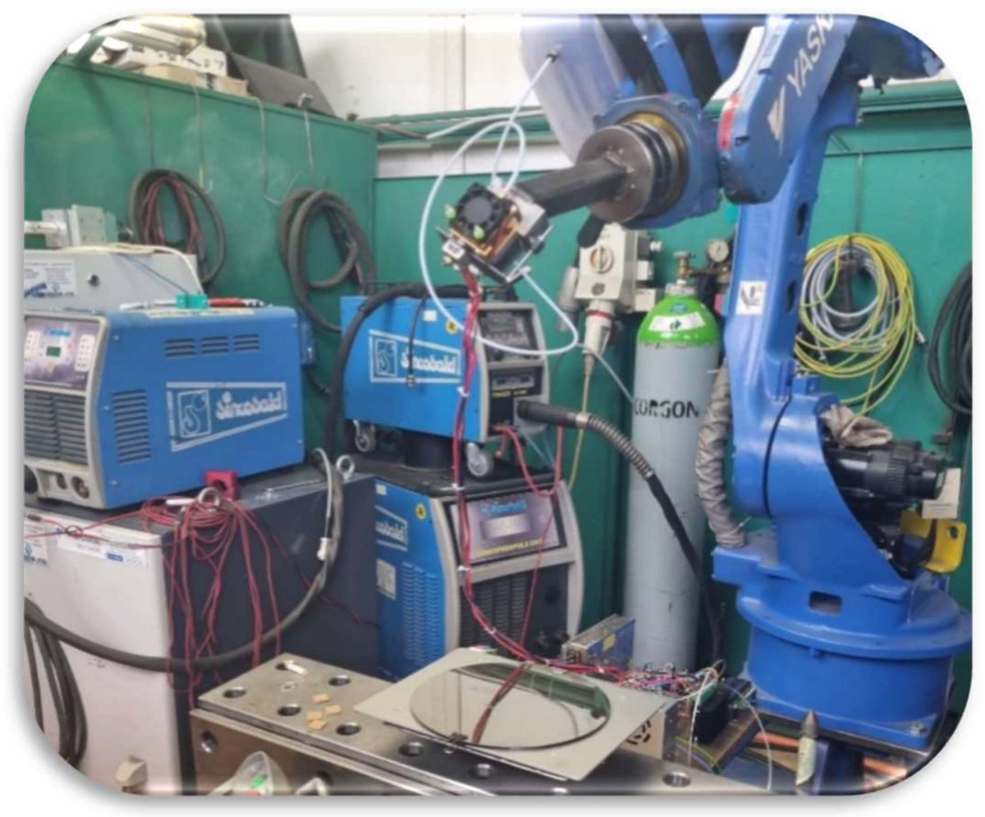
For PETG, the optimum temperature is between 230 - 260 degrees, the working table temperature is 60 degrees and the optimum speed is between 3.6 - 4.8 mm/s). The extrusion head system includes a thermal insulator, a thermal block, thermocouple, cooling fan, stepper motor and a 0.4 mm nozzle .
Operating principle and steps are:
- -
- Initialize the robot, then from the controller was give the command to the electronic controller module.
- -
- The microprocessor board gives the command to the extruder heating module and monitors until the desired temperature is reached, via the temperature probe integrated in the extruder.
- -
- Operates the support plate on which the part is moulded
- -
- Operates the display module, monitored parameters
- -
- Sends a pulse to the robot to initialize the program start
- -
- The robot is positioned in the provisional zone to run the extruder in idle until the desired viscosity is reached, for 10-15 seconds
- -
- If the wire feed speed or temperature is not as desired, it can be adjusted from the potentiometer. Potentiometer 1 for temperature and potentiometer 2 for feed speed
- -
- The robot waits for the command to execute the part
- -
- After the command, the 3D printing of the part starts
In Figure 2 is presented the block diagram of the process of making the plate that underlies the printing arm with the related circuits and components in the order of their use, also in Figure 3 you can see the placement of components on the plate that underlies the operation of the robotic arm [3,4,5,6,16].
4. Fused Deposition Modeling Process
Fused Deposition Modeling Process (FDM) is very open to different extrusions, materials, filament thickness and bed materials. The FDM technique is used in the current project. The 3D extruder is the part of the 3D printer that extrudes material in liquid or semi-liquid form to deposit it in successive layers within the 3D printing volume. In some cases, the extruder serves only to deposit a bonding agent used to solidify a material that is initially in powder form.
The robotic arm is a mechanical device that resemble the human arm. Mechanical arms can be programmed to do various tasks. Robotic arms are often used to perform tasks that are either harmful to humans, unsafe, unpleasant, or highly repetitive.
The extruder
The high temperature flexo reflow kit was chosen due to the efficiency of the printing materials which have higher melting points than standard ABS and PLA materials although in this study it was chosen to use Polietilen tereftalat glicol (PETG) as the material. This will facilitate the printing of nylon variants and flexible SIMPLE materials. The toolkit also includes a standard hot end for printing ABS and PLA if further studies are needed in the future.
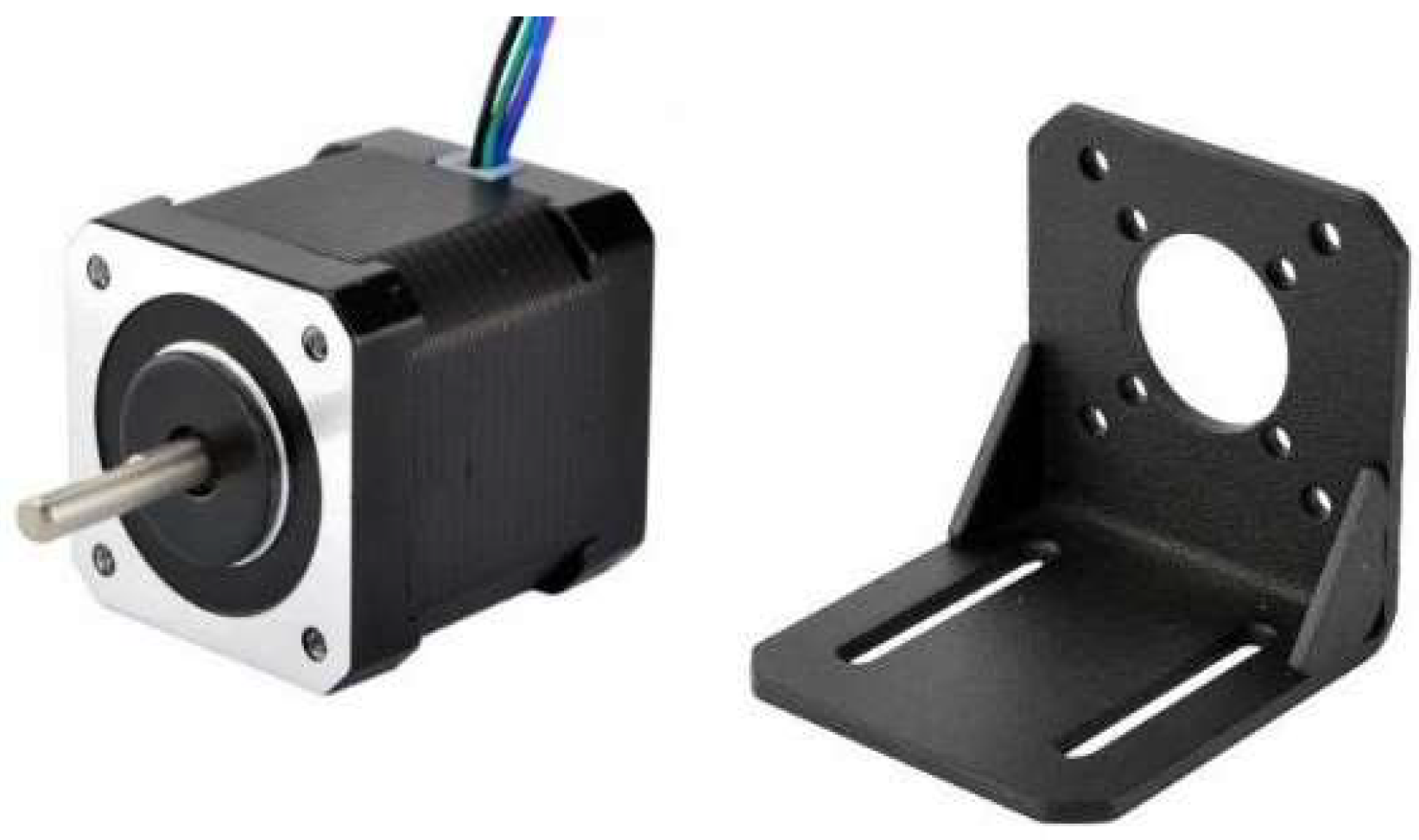
Drive system
To be able to 3D print with the extruder is needed a motor to feed the extruder. The extruder is designed to fit on a stepper motor.
Figure 4.
Components on the main board.
Electronics
An Arduino Uno was chosen to control the various fans, stepper motor and heating element.
Figure 5.
Arduino Uno.

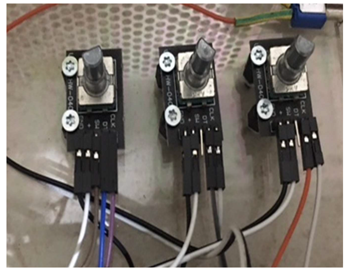
The encoder is a sensor that detects the angle of rotation or linear displacement. Encoders are used in devices that need to operate at high speeds and with high accuracy.
The method of controlling motor rotation by sensing motor speed and rotation angle using an encoder is called feedback control (closed loop method).
- -
- Encoder 1 for filament speed
- -
- Encoder 2 for extruder temperature
- -
- Encoder 3 for table temperature
Figure 6.
The three encoders.
After several attempts it was possible to optimize the base/main plate, which is the basis of the robot arm operation, the optimization was quite difficult because the components on the plate failed in a line, the thermocouples failed 3 times, it was necessary to supplement the current sources. Initially only one current source was considered, then it was concluded that two current sources were needed.
The material used is Polyethylene terephthalate (PETG) that in generally is thermoplastic (as opposed to thermosetting). This characteristic is related to the way the plastic responds to heat. There are some variants of this material (such as certain types of polyester) that are thermosetting. Thermoplastics become liquid at their melting point (around 260°C in the case of PET). PETG is a glycol-modified version of polyethylene terephthalate (PET), which is commonly used to produce water bottles. It is a semi-rigid material with good impact strength, but has a slightly softer surface, making it prone to wear. The material has an excellent thermal characteristics, allowing the plastic to cool efficiently with almost negligible deformation.
The advantages in 3D printing are easy to print, available in a wide variety of colours and especially transparencies but also there are disadvantages like limited bridging possibilities, spider-thin threads may appear on the surface of the print due to the characteristics of the filament.
In the following pictures you can see the steps of the product optimization, Figure 7 c represents the testing of a PETG filament [13,14,15].

Table 1.
Specifications for PETG.
| Features | |
|---|---|
| Durability | High |
| Material costs | Low |
| Strength | High |
| Flexibility | Low |
| Resistance | |
| Heat resistance | Medium |
| Chemical resistance | High |
| Fatigue resistance | High |
| Water resistance | High |
Steps in component development
At the first trials the thermocouples failed and then it was concluded that another source was needed in addition to the one considered in the first process simulation.
The first piece that was printed with the robot arm was a square made of PETG layers, which can be seen in the following figures. The whole research has been carried out over a period of one month and the process has not been optimized very well, so the studies will continue. The first printed piece showed a defect after the first 5 layers was covered. The defect has been caused by the cooling time between layers. After optimizing this parameter, the defect has not appeared anymore and even the next layers covered the defect from the first layers [10,11,12].
Figure 8.
First piece printed on the extruder robot arm.
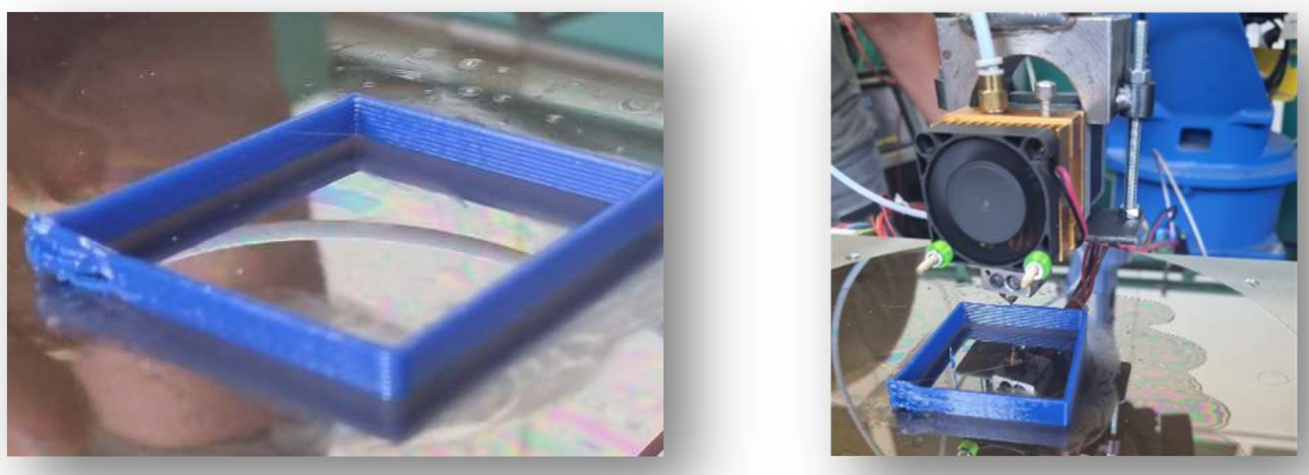
The printed piece was made of 20 layers, in the future the study will be extended to pieces with a more irregular shape and other materials. The main goal of this study was to realize the robot arm with the specific polymer extruder with the purpose of doing research studies on polymer printing on a robot [7,8,9].
5. Conclusion
The present paper represents the development of a robot arm that has an extruder that can print polymers. The information in the GCode contains the type of movement for the robot arm, the coordinates of the workspace it will move, the orientation of the extruder head, the speed of the robot arm movement, the extrusion volume during the printing movement and the extruder speed.
This study presents the development of a robot arm that will be able to print polymers (PLA, PET, PETG, ABS, etc.) so that the products obtained will have a much better deposition than on a professional printer, from studies and literature the composition of the layers will be more homogeneous (Pierre M. Larochelle and Ismayuzri B. Ishak, 2019). The printing speed is higher, and the cooling time is better than a professional printer [17,18].
The use of the capabilities of a robot in 5 or 6 DoF and combining with the features of the extruder the results obtained are higher than a professional printer.
In the study the experimental part of the work was quite difficult because there were problems in writing the code on the board as well as an erroneous alignment of the components, initially only one source was used, but as the research progressed it was concluded that two sources were needed.
Another issue of the study was the failure of some components such as the thermocouples, but by optimizing as much as possible, modifying some positions on the board, it was possible to complete the research.
As a conclusion or lesson from the experiment the most important steps are:
selecting the 3 parameters (filament speed, table temperature and temperature of the thermocouple, mounted directly on the extruder)[19].
reaching the optimal temperature, the extruder is ready to print the desired part.
Speed and temperature adjustments according to the material used.
The material used in this study was PETG, the optimum temperature is between 230 - 260 degrees, the working table temperature is 60 degrees, and the optimum speed is between 3.6 - 4.8 mm/s).
The extrusion head system includes a thermal insulator, a thermal block, thermocouple, cooling fan, stepper motor and a 4 mm nozzle. In the future, the process used by the robot arm will be optimized even more to obtain defect-free products.
Future studies will be extended to other materials and other shapes including lattice beam shapes, it is intended to use the full capabilities of both the robot and the new arm obtained from the experiment.
Author Contributions
Conceptualization, A.F and LS.; methodology, AF.; validation, AF., AF. and LS.; investigation, AF, resources, A.F and LS, data curation, AF., LS; AF, writing—original draft preparation, AF., L.S and ACF.; writing—review and editing, AF., L.S and ACF.; visualization, AF., L.S and ACF.; supervision, A.F and L.S.; project administration, A.F and L.S.; funding acquisition, A.F . L.S and ACF.
Funding
This research received no external funding.
Institutional Review Board Statement
Not applicable.
Informed Consent Statement
Not applicable.
Data Availability Statement
The data presented in this study are available on request from the corresponding author.
Acknowledgments
The collective would like to thank the technical colleagues who helped to this study.
Conflicts of Interest
The authors declare no conflict of interest.
References
- https://www.3dnatives.com/en/3d-technologies [accessed mar. 10 2023].
- Pierre M. Larochelle, Ismayuzri B. Ishak: A robot arm based additive manufacturing system, 2019 CCToMM Mechanisms, Machines, and Mechatronics (M3) Symposium.
- https://3dprintingindustry.com/3d-printing-basics-free-beginners-guide#05-materials [accessed mar. 10 2023].
- Loughborough University/AditiveManufacrurer Research Group https://www.lboro.ac.uk/research/amrg/about/whatisam/.
- G. R. BUICAN, Cercetări privind fabricarea prin topire selectivă cu laserul a pieselor din oțel inox 316 L Research Rgarding Manufacturing of 316L StainlessSteelPartsUsing Selective Laser MeltingProcess (SLM), teza de doctorat, Universitatea Transilvania Brasov, 2019.
- Becheru, Studiul obținerii prin depunere strat cu strat a unei fulii, disertatie, 2021, UPT.
- Jin, G.Q., Li, W.D., Tsai, C.F. and Wang, L. “Adaptive tool-path generation of rapid prototyping for complex product models.” Journal of Manufacturing Systems, Vol. 30, No. 3, pp. 154 – 164. ISSN 0278-6125.
- http://dx.doi.org/10.1016/j.jmsy.2011.05.007. 2011. [CrossRef]
- Phatak, A.M. and Pande, S. “Optimum part orientation in rapid prototyping using genetic algorithm.” Journal of Manufacturing Systems, Vol. 31, No. 4, pp. 395 – 402. ISSN 0278-6125.
- http://dx.doi.org/10.1016/j.jmsy.2012.07.001. Selected Papers of 40th North American Manufacturing Research Conference, 2012. [CrossRef]
- Firu, A., Țăpîrdea A., Chivu O., Feier A.I., Drăghici G.” The competences required by the new technologies. in Industry 4.0 and the development of employees' skills, ACTA TECHNICA NAPOCENSIS SERIES-APPLIED MATHEMATICS MECHANICS AND ENGINEERING, vol.64, No 1-S1,, 2021. 2021; S1.
- Feier, A., Banciu F., Ergonomic aspects of real and virtual welding tools, in Acta Tehnica Napocensis/Series Applied mathematics, mechanics and Engineering, vol.64, No 1-S1, 2021.
- Feier, A., Becheru A., Brindusoiu M., Blaga L. Process Transferability of Friction Riveting of AA2024-T351/Polyetherimide (PEI) Joints Using Hand-Driven, Low-Cost Drilling Equipment. Processes, 2021. Available online: https://www.mdpi.coan/2227-9717/9/8/1376.
- Johnson, R.O.; Burlhis, H.S. Polyetherimide: A new high-performance thermoplastic resin. J. Polym. Sci. Polym. Symp. 2007, 70, 129–143. [Google Scholar] [CrossRef]
- Modi, S.; Stevens, M.; Chess, M. Mixed Material Joining Advancements and Challenges. Cent. Automot. Res. 2017. Available online: http://www.cargroup.org/wp-content/uploads/2017/05/Joining-Whitepaper-Final_May16.pdf [accessed mar. 10 2023].
- Kabir, S.F.; Mathur, K.; Seyam, A.F.M. Seyam: A Critical Review on 3D Printed Continuous Fiber-Reinforced Composites: History, Mechanism, Materials, and Properties, Composite Structures; Elsevier: Amsterdam, The Netherlands, 2019. [Google Scholar]
- Ouyang, D.; Wei, X.; Li, N.; Li, Y.; Liu, L. Structural evolutions in 3D-printed Fe-based metallic glass fabricated by selective laser melting. Addit. Manuf. 2018, 23, 246–252. [Google Scholar] [CrossRef]
- Ozden, M.; Morley, N. Laser Additive Manufacturing of Fe-Based Magnetic Amorphous Alloys. Magnetochemistry 2021, 7, 20. [Google Scholar] [CrossRef]
- Maciąg, F.; Moskalewicz, T.; Kowalski, K.; Łukaszczyk, A.; Hadzhieva, Z.; Boccaccini, A.R. The Effect of Electrophoretic Deposition Parameters on the Microstructure and Adhesion of Zein Coatings to Titanium Substrates. Materials 2021, 14, 312. [Google Scholar] [CrossRef] [PubMed]
Figure 2.
Block diagram of the process.
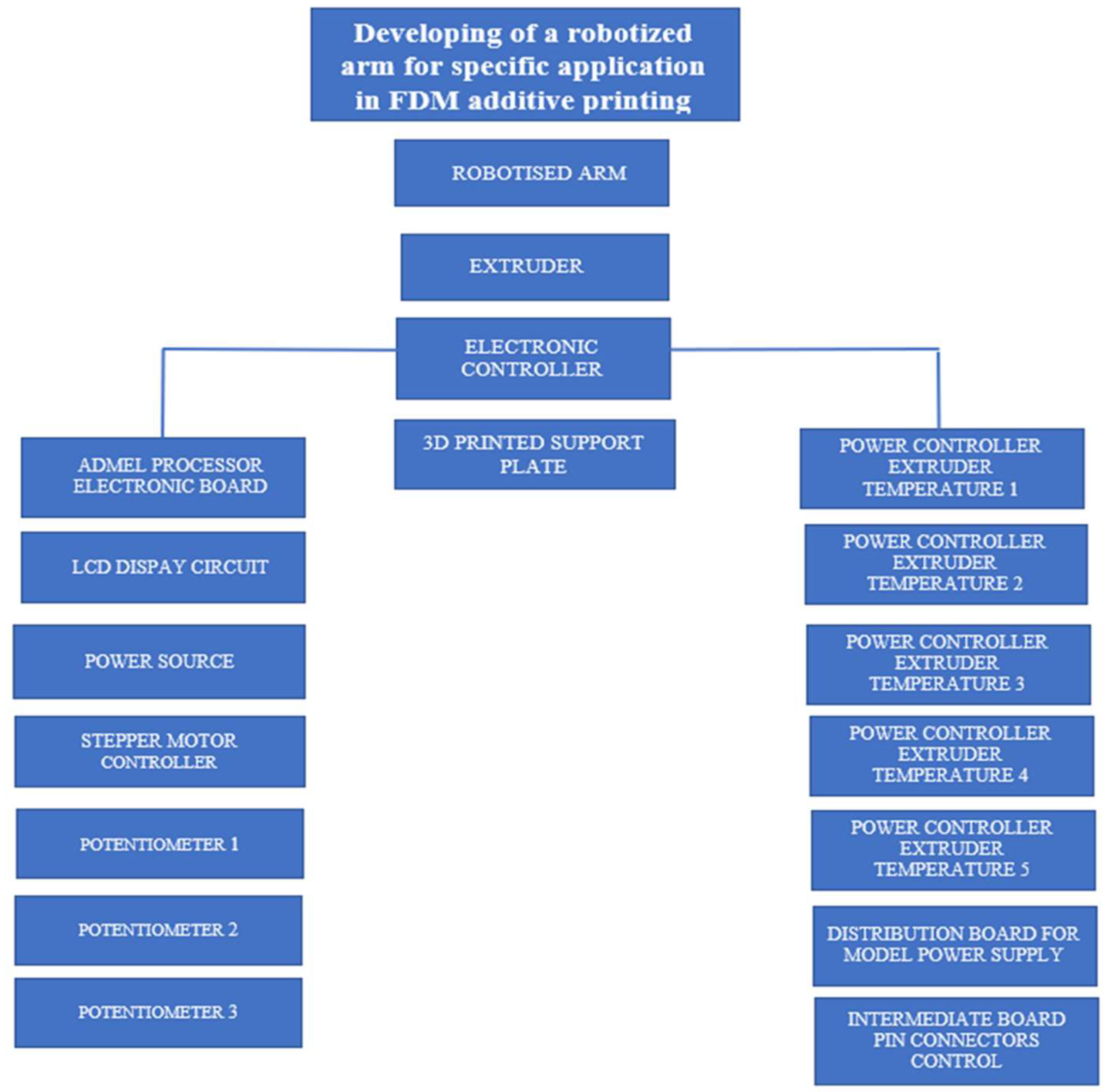
Figure 3.
Board with components.
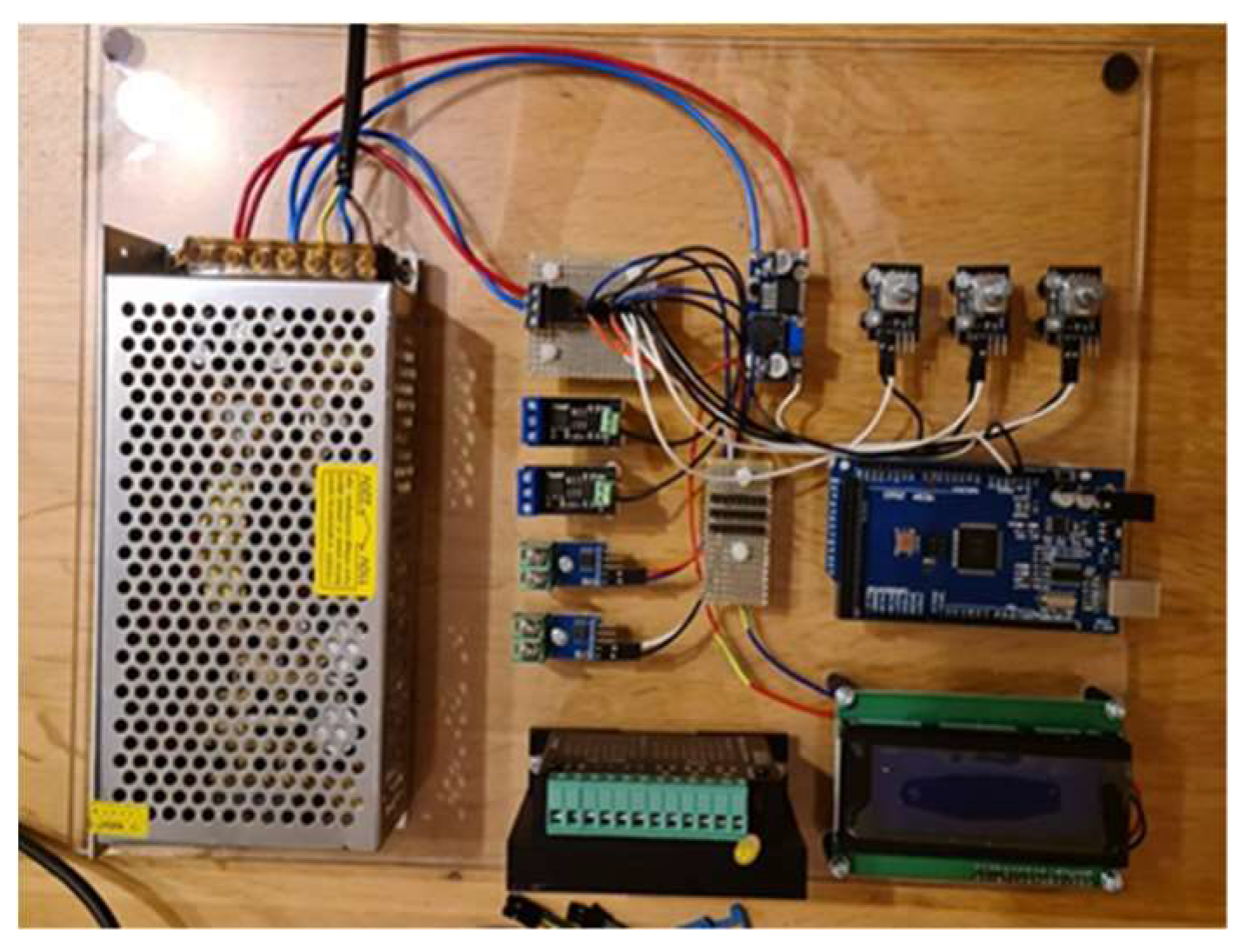
Figure 7.
The first steps in setting up the robot arm, the first printed layers.

Disclaimer/Publisher’s Note: The statements, opinions and data contained in all publications are solely those of the individual author(s) and contributor(s) and not of MDPI and/or the editor(s). MDPI and/or the editor(s) disclaim responsibility for any injury to people or property resulting from any ideas, methods, instructions or products referred to in the content. |
© 2024 by the authors. Licensee MDPI, Basel, Switzerland. This article is an open access article distributed under the terms and conditions of the Creative Commons Attribution (CC BY) license (https://creativecommons.org/licenses/by/4.0/).
Copyright: This open access article is published under a Creative Commons CC BY 4.0 license, which permit the free download, distribution, and reuse, provided that the author and preprint are cited in any reuse.


