1. Introduction
Automated generalization of residential areas is a popular and challenging research area in the field of geographic information system (GIS) mapping [
1]. In large-scale mapping of urban areas, residential areas are generally represented as polygons, which occupy a significant proportion of the map area [
2]. Various techniques are used for generalization, including selection, simplification, aggregation, displacement, exaggeration, and classification. Among these, simplification is one of the most commonly used methods [
3]. Building outline data extracted from remote sensing images and raster maps can be adversely affected by factors such as equipment accuracy, image resolution, and climate. Consequently, directly extracted buildings often have irregular shapes and jagged outlines, and building data are highly redundant. Therefore, appropriate simplification algorithms should be used to denoise and regularize extracted data to comply with mapping standards and adapt them to the representation capability of the feature map.
Various simplification algorithms have been proposed and can be classified into three types: vector-, raster-, and vector–raster-based algorithms. Vector-based algorithms are most commonly used for building outline simplification and include progressive simplification [
4,
5], dimensionality reduction [
6,
7,
8], least-squares adjustment [
9,
10,
11], constrained Delaunay triangulation [
2,
3,
4,
5,
6,
7,
8,
9,
10,
11,
12,
13,
14], feature edge extraction [
15], and template matching [
16,
17]. Progressive simplification methods use the sides adjacent to the concave and convex parts of a building to construct adjacent rectangles and perform simplification based on an area comparison to preserving the area and shape of the building. This method is primarily used for polygons with right-angled turns. Dimensionality reduction methods extract the skeleton of a surface, simplify it using linear processing, and restore it to a building outline surface with enhanced orthogonality. In least-squares adjustment methods, the boundary points are grouped using a set threshold value, and a least-squares adjustment model is used to simplify and regularize the building outline. Least-squares simplification is an optimization process. Constrained Delaunay triangulation methods partition the polygon into a set of triangles, and after identifying the triangle types, simplify the building outline by removing or moving triangle vertices while preserving, as much as possible, the surface area of the building. Adjacent four-point methods select a starting point and successively form a processing unit consisting of four adjacent points by moving clockwise or counterclockwise, gradually simplifying the building outline. This method involves simple operations and can be easily implemented to solve local problems. Template matching methods replace the original building with the closest matching shape from the template database. This method preserves the shapes and distribution patterns of buildings; however, its results are overly reliant on template databases. The method based on mathematical morphology [
18,
19] is a representative raster-based simplification method. This simplification is achieved through the combined application of basic morphological operations, including dilation, erosion, opening, and closing. This method is efficient and easy to control; however, it is primarily used for building outlines with evident orthogonal features. In addition, some studies have focused on vector–raster-based simplification methods, such as those involving the use of backpropagation neural networks [
20]. A backpropagation neural network model can be used to acquire cartographic knowledge and simplify the localized perception of raster elements. However, vector–raster-based methods generally require the conversion of data between the vector and raster formats, which can result in a certain loss of accuracy.
These algorithms are important tools that enable us to approach the right-angled polygon building outlines with jagged edges simplification process from different perspectives. However, for the automated extraction of highly irregular building outlines directly from remote sensing images and raster maps, many simplification algorithms cannot meet mapping standards. Moreover, most simplification algorithms cannot satisfy a set of comprehensive generalization rules related to redundant point processing, building orthogonality, and overall outline regularization, or require auxiliary operations, such as coordinate rotation, data conversion, or manual trimming. If multiple algorithms are used successively, the simplification process becomes overly complex and algorithm cohesion and coupling are adversely affected, leading to gradual data loss and poor results.
The present study proposes a regularization algorithm for vector data of building outlines extracted directly from remote sensing images and raster maps. The proposed method populates the minimum bounding rectangle (MBR) of a building outline with a square grid and successively analyzes the overlay of the grid and the original building outline to identify its valid feature points, eliminate redundant points, and extract critical turning points. Finally, the proposed algorithm sorts the extracted points and uses them to reconstruct a simplified building outline. Compared to the current popular regularization methods, such as machine learning and deep learning, this study adopts the traditional geometry method to operate the building data in vector form, which has the advantages of an easy implementation process, low requirements on computer hardware, and strong reliability. By analyzing the regularization effect of the proposed method on various resolution data and comparing the proposed method with other methods, we demonstrated that the proposed method fully considers the requirements of direction, position, shape, and area preservation in the simplification process of residential land elements and strengthens the parallel and right-angled characteristics of right-angle polygon buildings, with a good regularization effect.
2. Methodology
Building outline simplification should follow the principles of area preservation, shape similarity, and boundary regularity [
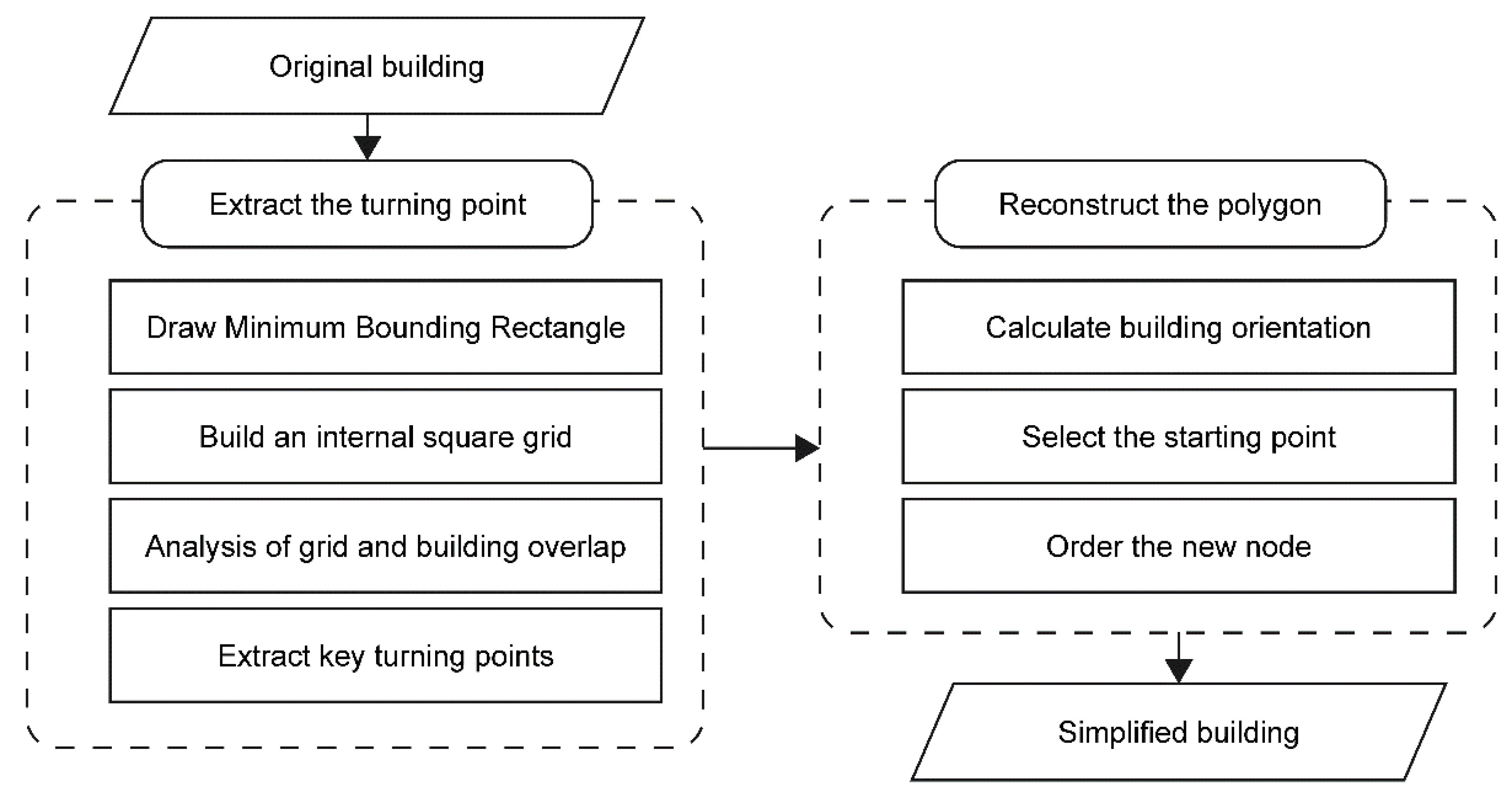
10]. Based on a comprehensive understanding of building structure characteristics, synthesis principles, and cartographic representations, the proposed method divides the regularization process of right-angled polygon building outlines into two parts: turning-point extraction and polygon reconstruction. A flowchart of this process is shown in
Figure 1.
Part 1: Extraction of turning points. This part is divided into four steps: (1) constructing the MBR; (2) generating a grid mesh inside the MBR using the minimum visibility threshold as a constraint; (3) grid-by-grid intersecting the overlay of the grid with the original building, and preserving the region consisting of grid cells with an area of not less than half a cell; and (4) extracting the building outline points from the selected overall region and removing redundant points. The turning points extracted using these steps comprised the smallest point set of the building outline. However, because this is an unordered point set, it cannot be used directly to reconstruct the polygons. After using an appropriate algorithm to sort the points in a clockwise or counterclockwise order, the building outline can be reconstructed.
Part 2: Building-outline reconstruction. This part is divided into three steps: (1) determining the orientation axis of the building, (2) selecting the point with the smallest abscissa in the turning point set as the starting point, and (3) sorting the new nodes based on whether each side is parallel or perpendicular to the building orientation axis and reconstructing the building outline.
3. Extraction Algorithm of Building Outline Points
3.1. Construction of the Minimum Bounding Rectangle
The MBR of a polygon can be classified into two types: the minimum-area bounding rectangle (MABR) and the minimum-perimeter bounding rectangle (MPBR). As buildings are generally represented on maps as rectangular polygons, the difference between the two types of bounding rectangles is typically insignificant. In this study, we used MABR to better represent the directional characteristics of buildings. The MABR was obtained using the method described in Doytsher [
21], which consists of the following steps:
(1) The minimum convex hull of the polygon is calculated using the Graham scan algorithm [
22], as illustrated in
Figure 2a and b.
(2) One side of the convex hull is selected as the base side, and the convex hull is rotated about the left endpoint of the base side until it becomes parallel to the horizontal axis. The MBR area enclosed by the minimum and maximum coordinates of the rotated convex hull is calculated and stored, and the base side name and rotation angle are stored.
(3) The remaining sides are successively selected, and step 2 is repeated.
Figure 2d shows the MBR with segment 1–2 as the base side, and
Figure 2e shows the MBR with segment 2–3 as the base side.
(4) The MBR with the smallest area is selected, and the left endpoint of the corresponding rotated side is used as the pivot point to rotate the MBR in the opposite direction by the corresponding angle, thereby obtaining the MABR.
3.2. Mesh Construction
Typically, opposite sides of a right-angled polygon building outline are parallel, and adjacent sides are perpendicular [
10]. Therefore, this study constructed a grid composed of perpendicular and parallel segments as the operating unit for simplification. The proposed grid improves the geometric accuracy of the building outline and ensures effective simplification.
3.2.1. Principles and Threshold Values of Grid Construction
The aim of building outline simplification is to eliminate detailed features of the building, which are smaller than the minimum visible length (generally, 0.3 mm is used for composite images), thereby ensuring a consistent visual perception of the object [
20]. This study used overlay analysis to construct a grid. The grid spacing should be greater than the minimum visible length to ensure that all the building edges are visible to the human eye after simplification. The threshold “r” is set to be no less than the ground distance corresponding to the smallest visible length at a given map scale. For example, the threshold value for a map scale of 1:5000 should be no less than 1.5 m, and for a scale of 1:10000, it should be no less than 3 m.
3.2.2. MBR Node Selection and Grid Construction
The grid is constructed by populating each side of the building outline MBR with nodes using the following steps:
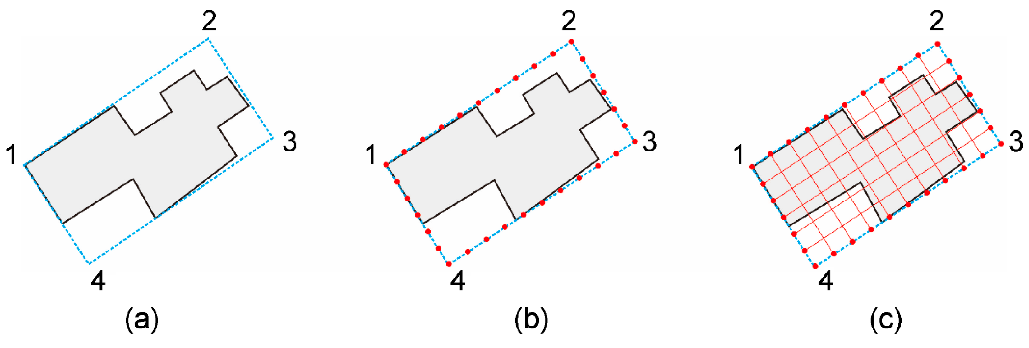
(1) The ground distance corresponding to the long and short edges of the MBR is calculated; for example, in
Figure 3(a), the long edges 1–2 and 3–4 and the short edges 2–3 and 4–1 can be used.
(2) The ground distance corresponding to each side is divided by the visible length threshold, and the result is rounded down to obtain the number of grid rows and columns (If the result is 0, the ground distance of the corresponding MBR side is less than r, and a value of 1 should be selected, which is equivalent to an exaggeration operation).
(3) The ground distance is divided by the corresponding number of rows and columns to obtain the grid and column spacing.
(4) Each side of the MBR is populated with nodes using the calculated row and column spacing, as shown in
Figure 3b.
(5) The corresponding nodes of the long and short edges of the MBR are connected to construct the grid, as shown in
Figure 3c.
3.3. Selection of Turning Points Through Overlay Analysis
Area preservation is another important rule that must be considered when using a simplified algorithm [
2]. This study proposes a grid-by-grid overlay analysis method that analyzes the overlay of each grid with the original building outline, eliminates elements whose intersection is less than half the area of a single grid cell, and retains and combines the remaining grid cells to generate a simplified outline.
3.3.1. Construction of the Initial Grid
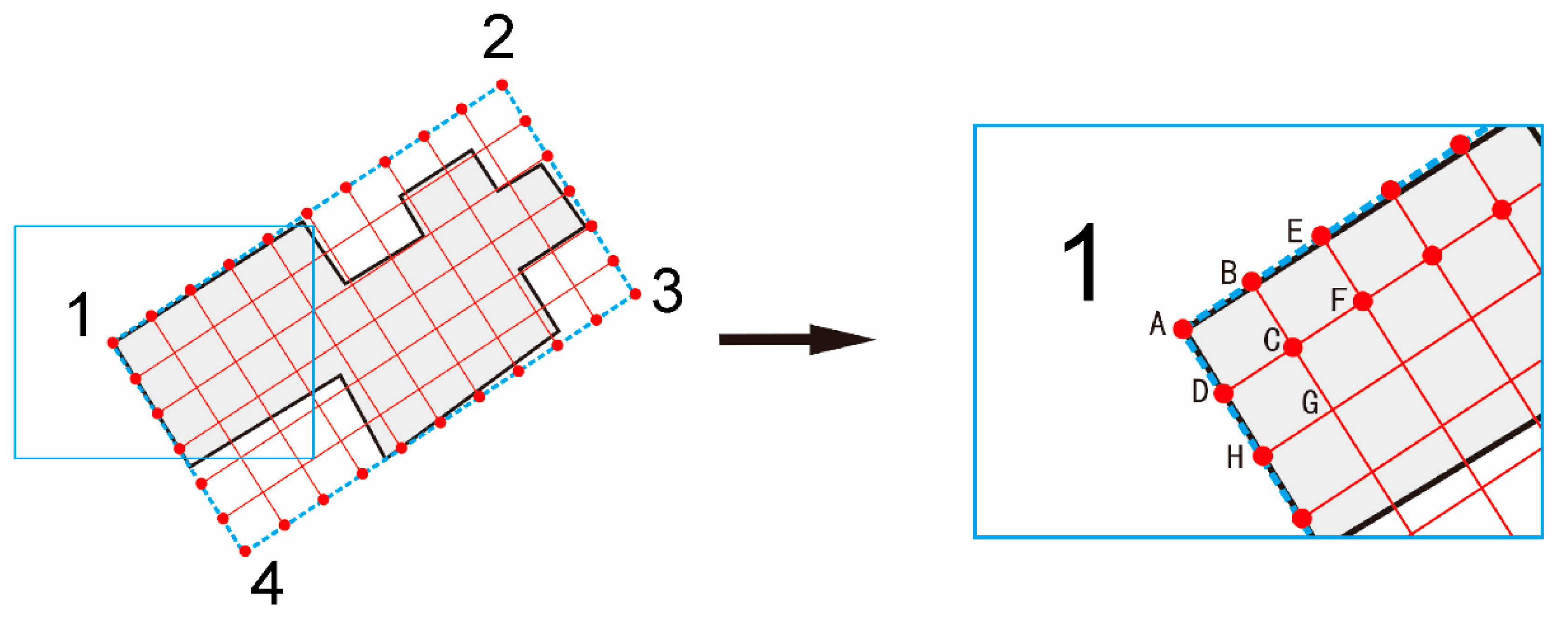
Any point of the MBR is selected as the starting point; for example, in
Figure 4, point A is selected as the starting point from which the four vertices of the grid cell are generated clockwise or counterclockwise, constructing the initial grid cell. In
Figure 4, the initial grid cell ABCDA is constructed clockwise from starting point A.
3.3.2. Sequential Traversal of All Grid Cells
After selecting one control point, the grid surface is constructed by moving the control point successively until the entire grid has been traversed as follows:
(1) The starting point described above is selected as the first control point, and the same method used to construct the initial surface is used to generate the control surface. In
Figure 4, point A is selected as the initial control point and ABCDA is the initial control surface.
(2) Traverse one step along the long or short side (row or column) to obtain the second control point. As shown in
Figure 4, the control point is moved along the long side in one step (column) from point A to point B, and BEFCB is the second control surface.
(3) After traversing all grid cells in the first row, the control point is moved along the short side over one step (row) from point A to point D, and all grid cells in the second row are traversed successively in the same manner as those in the first row.
(4) This process is repeated until the entire grid is traversed.
3.3.3. Overlay Analysis and Turning Point Selection
In the process of traversing the grid, the following algorithm is proposed to extract the effective turning points and remove redundant points.
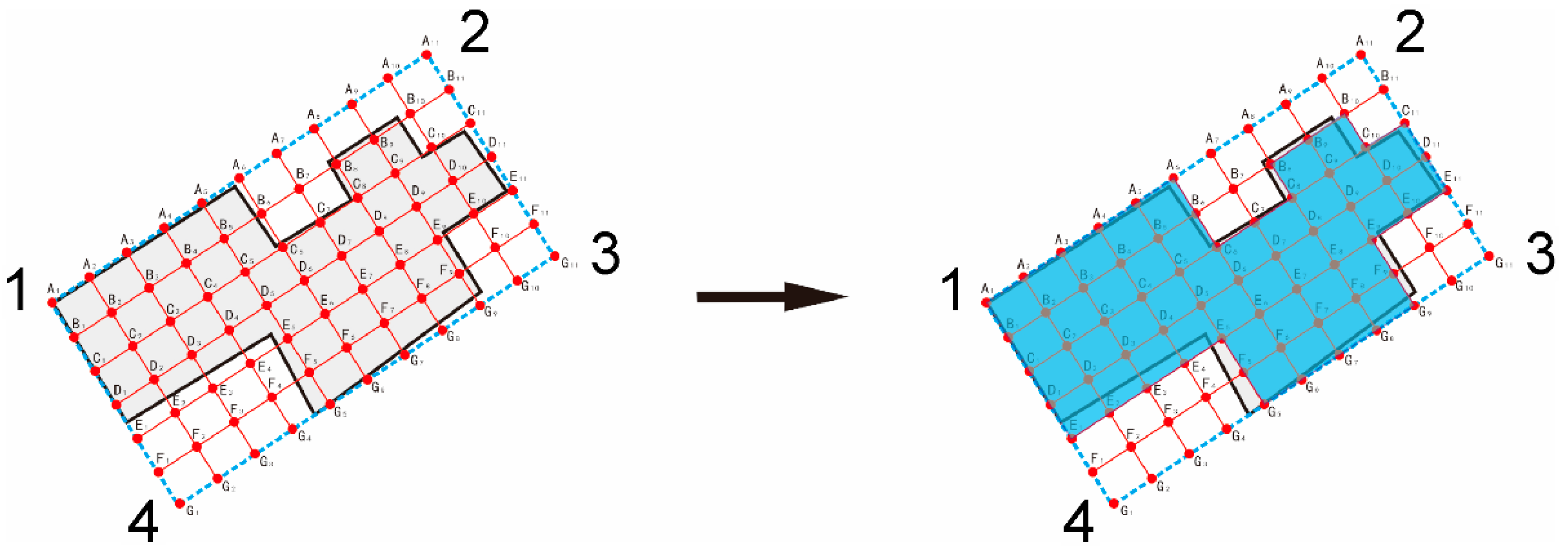
Create a coordinate set to store the coordinates of the turning points. Starting from the initial control point, the intersection of each grid with the original building outline overlay is calculated. In this step, three types of conditions may be encountered: first, the intersection is empty; second, the intersection is not empty, but the area is less than half of the grid cell area; and third, the intersection is not empty and is greater than or equal to half of the grid cell area. When the first two circumstances are encountered, the control surface points are not stored, and the next control surface is calculated. When the third condition is encountered, each of the four points defining the control surface is first compared with the elements contained in; if any of the points that has already been stored in , it is deleted from; if any point has not yet been stored in, then it is stored in.
For example, in
Figure 5, the initial control area A
1A
2B
2B
1A
1 is the third type of intersection. After processing, points A
1, A
2, B
2, and B
1 are stored in
, thereby obtaining
. The second control area A
2A
3B
3B
2A
2 is the third type of intersection. However, because points A
2 and B
2 have already been stored in
, they are deleted from
, whereas points A
3 and B
3, which have not yet been stored in
, are added to
, thereby obtaining
. After completing the above iterations for the first row, we obtain
. It is evident that the proposed algorithm skillfully eliminates redundant points along the building outline and stores only right-angled turning points.
After the overlay analysis method is successively applied to the remaining rows, turning point set is obtained.
It should be noted that the turning point C6 was first stored in during the analysis of the control surface B5B6C6C5B5 and was later removed from during the analysis of C5C6D6D5C5; however, it was added again to during the analysis of C6C7D7D6C6. Points C8 and C10 undergo a similar store–delete–store process.
4. Reconstruction Algorithm of the Building Outline
The elements in the turning point set
obtained in
Section 3.3.3 have not been arranged in a clockwise or counterclockwise order, so they cannot be used directly to reconstruct the building outline. This section proposes a sorting algorithm for the outline points of a rectangular polygon and analyzes the characteristics of turning points with reference to building orientation. By arranging the turning points of the outline in order, the proposed algorithm allows for a regularized reconstruction of the building outline.
4.1. Basic Algorithm
4.1.1. Calculation of Building Orientation
The orientation direction of a building is an important spatial constraint in map generalization. Some commonly used methods for calculating building orientation include the longest edge, weighted bisector, statistical weighting, MBR, and wall average [
23]. In this study, the MBR method has already been used to construct the grid and obtain the turning point set
, and hence, we used it to calculate building orientation.
4.1.2. MBR-based Calculation of Building Orientation
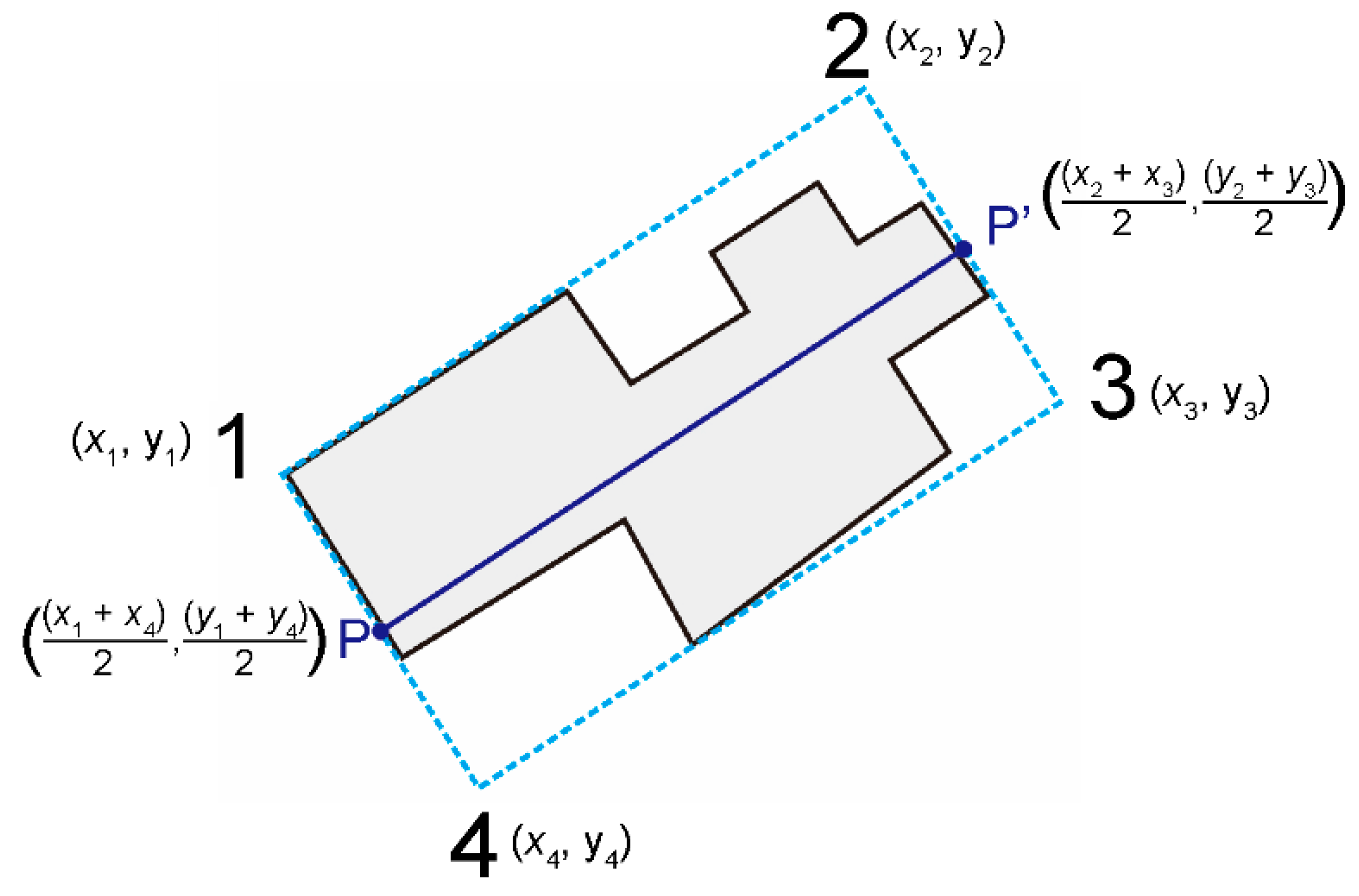
Using the coordinates of the four vertices of the MBR obtained in
Section 3.1, we calculate dthe midpoints of the two short MBR edges to determine the MBR orientation; in
Figure 6, PP’ is the orientation of the MBR, which is also the orientation of the building.
4.1.3. Calculation of the Angle Between Two Lines
The included angle of two lines can be calculated using Equation (1), in which k
1 and k
2 are the slopes of the two lines, respectively, and
θ is the angle between the two lines. The slope of this line is given by Eq. (2), where k is the slope of the segment connecting points A (
,
) and B (
,
).
An acute angle between two lines is an angle formed by the two lines that is less than 90°. As the calculated angle will not always be acute, when the calculated angle exceeds 90°, it should be converted to an acute angle using the expression 180°−θ.
4.2. Sorting Algorithm for Rectangular Building Outline Points
Because all turning points extracted in the preceding section of this study are grid vertices, and grid lines are either perpendicular or parallel to the orientation axis of the building, the segment between any two adjacent turning points will also be either perpendicular or parallel to the orientation axis. Based on this characteristic of the above building outline, this study proposes a sorting algorithm for the outline points of a rectangular building, which consists of the following steps:
(1) Traverse the turning point coordinate set to find the point with the smallest abscissa value and use it as the control point . If more than one point is found, select the one with the smallest ordinate value and use it as the control point and as the starting point of the polygon generalization result set . In addition, remove from any elements that have the same value as the starting point.
(2) Traverse all points in and find any points that form a segment with point , that is parallel/perpendicular (when iterating steps 2–4, exchange the parallel/perpendicular relationship with each iteration) with or to the orientation axis and do not intersect the skeleton of the original building outline; then copy and place those points in a temporary set .
(3) If contains only one element, it is designated as the temporary point . If contains multiple elements, calculate the Euclidean distance from each element to(), and use the element corresponding to as the temporary point . Clear.
(4) Input at the end of and set as the new control point; delete from any elements with the same value as.
(5) Repeat steps 2 to 4 until becomes empty.
(6) Copy the first element in set to the end of , so that the point set forms a closed figure.
The proposed sorting algorithm uses the orientation axis of the original building as a reference and operates based on the principle that two adjacent points on the building outline form a segment that is parallel or perpendicular to the orientation axis. After selecting the starting point, it systematically searches for the next node that satisfies the above condition and repeats this process until all outline nodes are arranged sequentially. The turning point set extracted using the method illustrated in
Figure 5 is sorted as shown in
Figure 7. First, point A
1, which has the lowest abscissa value, is set as the starting control point. Next, the point set is searched to find another point that forms a segment with A
1, which is parallel with PP′; only A
6 satisfies this condition. When A
6 is used as the control point, the point set is searched to find a point that forms a segment with A
6 perpendicular to PP′; only C
6 satisfies this condition. When C
6 is used as the control point, the point set is searched to find the point that forms a segment with C
6, which is parallel to the orientation axis PP’. Three points, namely, C
8, C
10 and C
11, satisfy this condition; however, point C
8 is selected because it is the closest to the control point, and the segment formed by these two points does not intersect the original building outline.
After all iterations are completed, the sorted point set is =.
5. Experiment and Analysis
The proposed algorithm was developed in GenerMap V3.0, a secondary independent development system, on the Visual Studio 2019 platform using the C++ programming language. Building-outline data extracted from remote sensing images using machine-learning or deep-learning methods were selected for the experiment. To verify the performance of the proposed algorithm, we used the simplification results of different-precision data under different thresholds and same-precision data processed by other simplification algorithms to perform a comparative analysis.
5.1. Quality Indicators for the Evaluation of Results of Simplification
To evaluate the performance of the proposed simplification algorithm, we selected six quantitative indicators to measure the effectiveness of the simplification. The following six evaluation indicators are established based on the constraint rules of building outline regularization: orientation retention, area-change rate, right-angle ratio, data-compression ratio, spatial similarity, and positional change in the building outline before and after simplification.
(1) Orientation retention (OT). Measures the change in the MBR orientation, given by:
In Eq. (3), and represent the angles between the long edges of the MBR and x-axis before and after simplification, respectively.
(2) Area-change rate (OS): This measures the change in the area of the building outline before and after simplification. It is given by
In Eq. (4), andrepresent the area of the building outline before and after simplification, respectively.
(3) Right-angle ratio (OR). Measures the orthogonality of the building outline before and after simplification based on the number of right angles among the interior angles of the polygon, which is given by
In Eq. (5), and represent the number of right angles and total number of interior angles, respectively, after simplification.
(4) Data-compression ratio (OD). represents the effectiveness of data compression by calculating the reduction in the number of nodes after simplification. It is given by
In Eq. (6), andrepresent the number of nodes that make up the building outline before and after simplification, respectively.
(5) Spatial similarity (OG). Measures the ratio of the building area overlapped before and after the simplification. It is given by
In Eq. (7), Sa∩b is the intersection area of the original and the simplified building; Sa is the building area before simplification.
(6) Positional change (OP): This is the change in the position of the building outline centroid after simplification. It is given by
In Eq. (8), P1(, ) and P2(, ) are the centroid coordinates before and after the simplification, respectively.
5.2. Algorithm Performance Based on the Simplification of Different-source Data
We selected remote sensing images with three resolutions of 0.075, 0.5, and 1 m in a certain area and used the deep-learning approach in Qiu et al. [
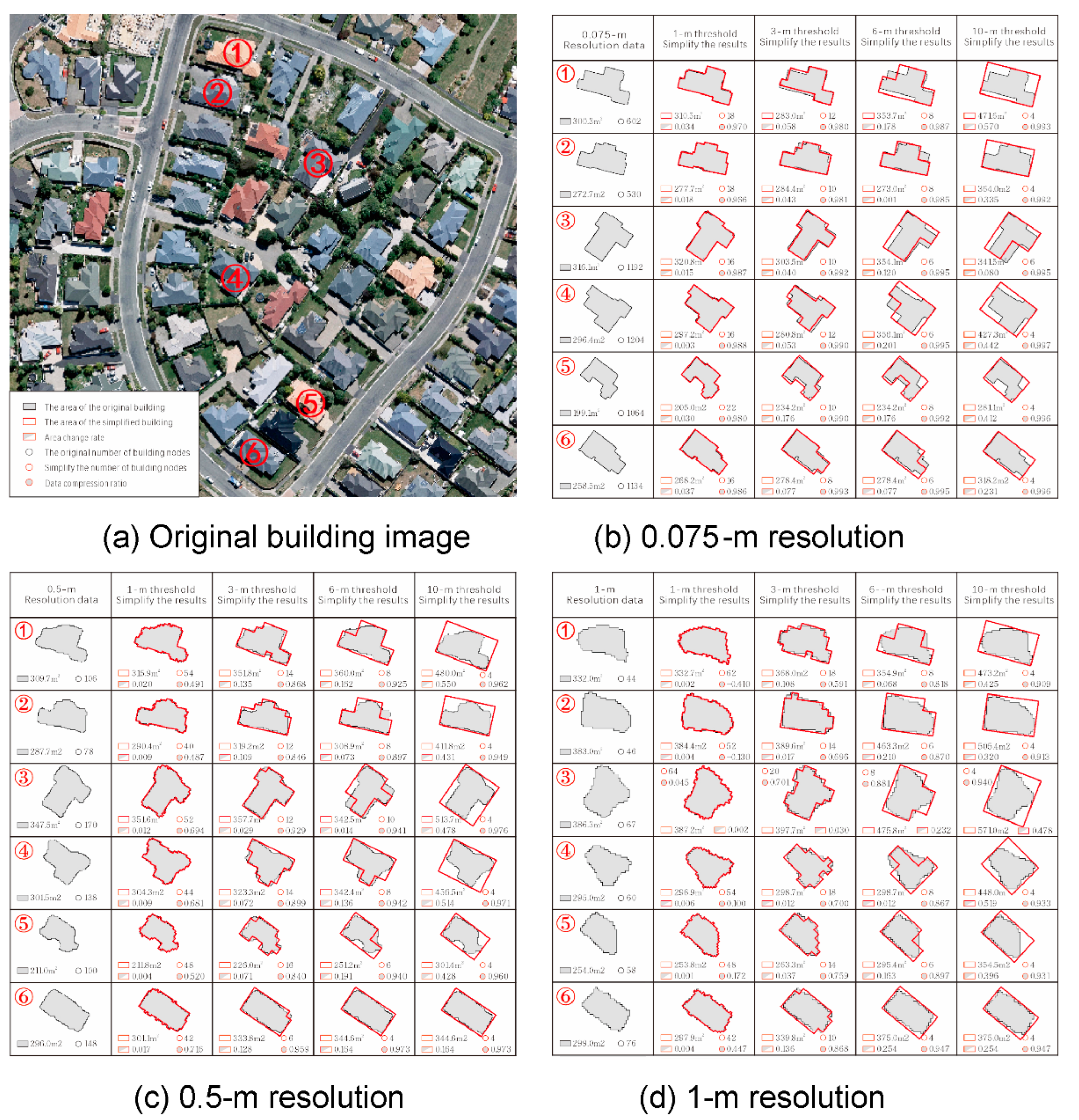
24] to extract building outlines, which were used as experimental data, and six data with different shapes were selected for analysis. Threshold values were determined using the method described in
Section 3.2.1. Results of simplification for different thresholds are shown in
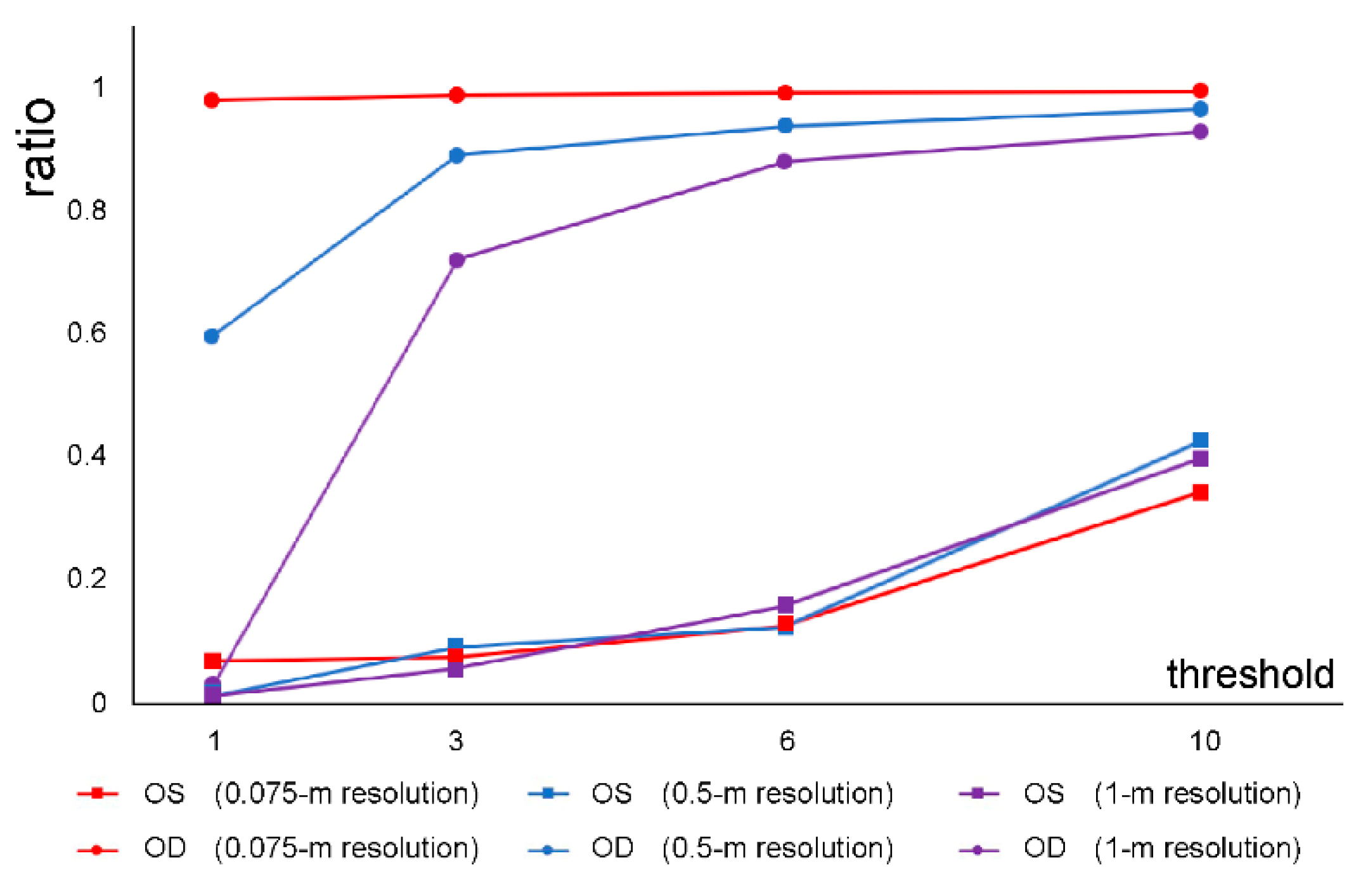
Figure 8, and those for different-resolution data at different threshold values are shown in
Figure 9.
When high-resolution images of buildings are used, although the amount of extracted original data is large, the shapes of the simplified building outlines are closer to the original outlines and are more orthogonal. The proposed simplification algorithm can reduce the number of nodes and perform well even under low-threshold conditions. When different-resolution data are simplified under different threshold conditions, the area remains stable, indicating that data resolution has little effect on area preservation.
Furthermore, it is evident from
Figure 8 that the results of simplification are directly related to the resolution of the remote sensing image; therefore, an appropriate threshold range should be selected for images with different resolutions. For example, when a 1-m threshold was used for 0.075-m data, the simplified outline had a small number of jagged edges, and when the threshold was set to 3 m, the building outline was more regular. Compared with the 3-m threshold, when a 6-m threshold was used, the building outline was oversimplified; therefore, some outline details were lost. For the 0.5-m and 1-m resolution data, when a threshold of 1 m was used, the simplified outlines had clearly visible jagged edges. Under a threshold of 3 m, the number of jagged edges was small, and under the 6-m threshold, the simplified outlines were relatively regular, and their area was well preserved. When a threshold of 10-m was selected, although the simplification algorithm produced regular building outlines for all three resolutions, the building areas changed significantly. Therefore, this threshold was not recommended.
During the simplification process, by establishing the MBR and the internal grid, the proposed algorithm constrains the orientation of the building outline and ensures that its interior angles are orthogonal. It uses a from-large-to-small processing strategy, which implies that it approaches the overall simplification process by operating only in areas close to the building outline, preserving, to a reasonable extent, the spatial and positional similarities between the original and simplified buildings. Therefore, only two indicators, OS and OD, are required to sufficiently reflect the effectiveness of the regularization process under different thresholds.
Figure 9 shows the effectiveness of the simplification algorithm for different-resolution data under different thresholds based on OS and OD values: the closer the OS is to 0, the more effective the simplification, and the closer the OD is to 1, the better the simplification effect. Therefore, high-resolution data allow the use of a wider interval of threshold values; as the data resolution decreases, the range of threshold values that produces reliable results gradually decreases. The ranges of reliable threshold values for all three data resolutions are listed in
Table 1.
The proposed algorithm can use experimental iterations and evaluation indicators to determine effective threshold values and the optimal threshold that meets the mapping requirements for data with different resolutions. The proposed method is more versatile than other simplification algorithms.
5.3. Comparison with Other Simplification Algorithms Based on Same-Source Data
In this section, we used building data extracted from 0.5-m resolution image data of a certain area to compare the simplification results of the proposed method with those of the rectangular fitting [
25], template matching [
17], adjacent-four-points [
15], and iterative [
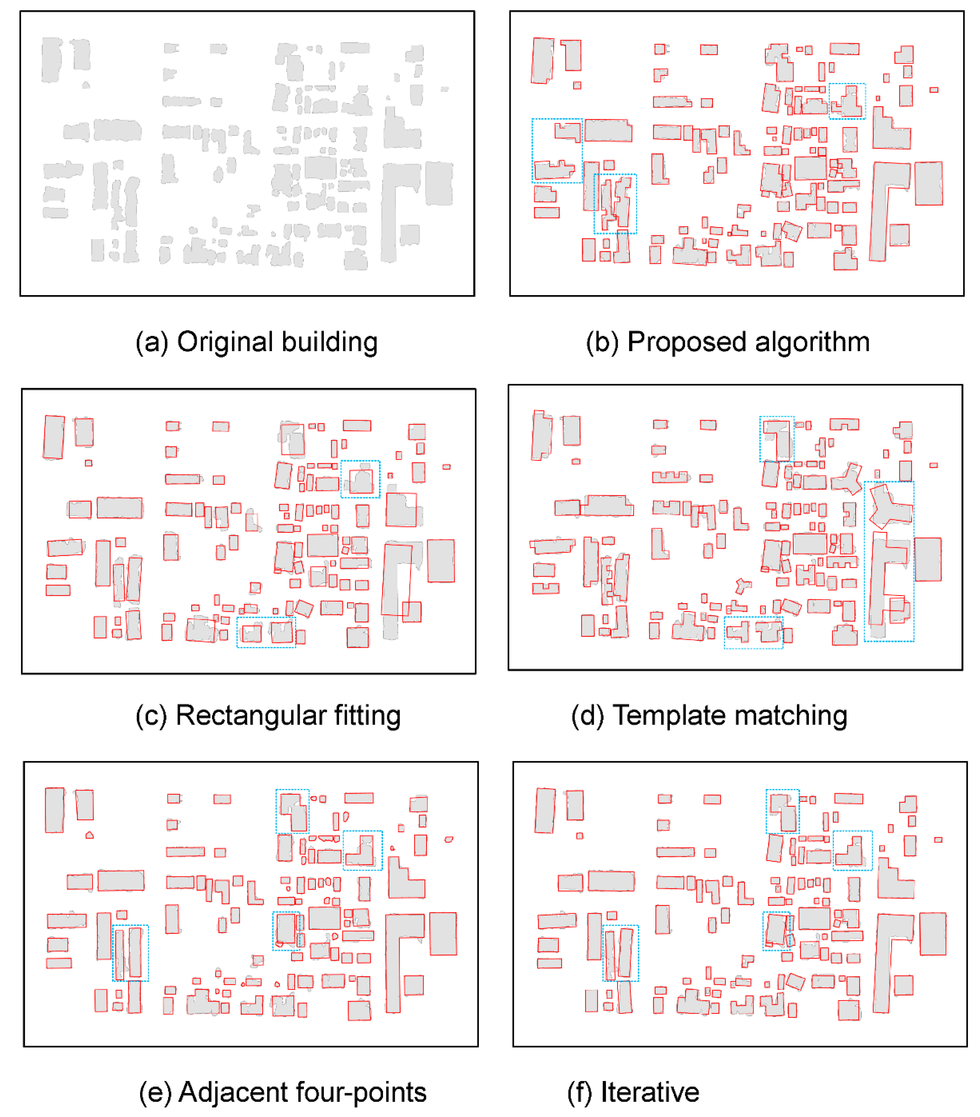
26] methods. The experimental area contained 104 buildings with different shapes. Based on the experimental results presented in
Section 5.2, a threshold of 6 m was selected. The simplified results are shown in
Figure 10. The average values of the six evaluation indicators for each method are listed in
Table 2.
The experimental results are as follows:
(1) In the rectangular fitting method, the building outline is replaced with a scaled MBR. During the scaling process, constraining rules are imposed on the building area and its centroid position to maintain consistency with the original building. This method exhibited the best performance in terms of OR, OT, OS, OD, and OP. However, the blue rectangular areas in
Figure 10c show that the simplified outlines are significantly different from the complex outlines of the original buildings, indicating that the spatial similarity between the original and simplified buildings is low. Therefore, this method is suitable only for simplifying rectangular buildings and should not be used for complex outlines. The template matching method can be viewed as an improved rectangular fitting method, with a rectangular outline supplemented with a variety of templates of other shapes. However, the disadvantage of this method is that its simplification effectiveness depends on the template database. For example, the blue rectangular areas in
Figure 10d indicate that the simplification method produces poor results when the template does not match the outline of the original building well. Therefore, although the evaluation results of the rectangular fitting and template-matching methods are comparable to those of the proposed algorithm, the two methods are not as versatile as the proposed algorithm.
(2) The adjacent-four-point and iterative methods use local processing strategies, which can consider all evaluation indicators, producing good results with respect to direction, area, shape, and positional similarity. However, the blue-rectangle-marked areas in
Figure 10e and f show that when simplifying relatively complex building outlines, these two methods tend to oversimplify the building outline, leading to a significantly low OG. The adjacent-four-point method also has some shortcomings in terms of OR.
The simplification process should be based on the premise that all evaluation indicators of the simplification method meet the required mapping standards, producing results that fully preserve the details of the building outline and its other characteristics, including orthogonality, orientation, and position.
Table 2 and
Figure 10 show that the proposed algorithm exhibits the best performance in terms of OR, OT, and OG. Under the premise of satisfying the minimum visible length condition, the change in the shape of the building outline can be controlled by retaining additional details. For example, in the blue-rectangle-marked areas in
Figure 10b, the number of nodes used to define building outlines was slightly higher, but the outlines are more detailed, which not only allows the preservation of the building shape more effectively but also preserves the orthogonality of the outline edges. When the orientation of the building outline remains unchanged, changes in building position and area can be effectively controlled through local processing strategies. Based on the above comprehensive analysis of the results of simplification using various evaluation indicators, we found that the proposed algorithm meets the required mapping standards and produces good simplification results.
6. Conclusions
In this study, we propose a targeting generalization algorithm that uses machine-learning or deep-learning methods to extract vector data of building outlines from remote sensing images based on right-angled polygon building outlines regularization principles. The proposed method consists of the following steps: (1) The MBR of the building outline is constructed and used as a “working area” to limit the change in the position of the building outline during the analysis. (2) Based on the from-large-to-small processing strategy, the MBR is populated with perpendicular intersecting segments that form a square grid to improve the orthogonality of the simplified building outline while controlling the changes in the area and structural morphology of the building outline during simplification. (3) Ordering outline nodes using the orientation axis of the building outline as a reference to control the orientation of the building before and after simplification. Experimental results showed that the proposed method can simultaneously and effectively preserve the structure, area, position, and orientation of a simplified outline, providing a feasible method for regularizing building outlines using vector data extracted directly from remote sensing images and raster maps. The proposed method has not been used to consider special cases such as the simplification of building outlines containing empty spaces or complex shapes; therefore, further research is required.
Author Contributions
Kong Linghui: Investigation, Methodology, Visualization, Writing - original draft; Qian Haizhong: Formal analysis, Funding acquisition, Supervision; Wu Yuqing: Writing - review & editing; Niu Xinyu: Project administration, Software; Wang Di: Validation; Huang Zhekun: Data curation, Resources.
Funding
This work was supported by The National Natural Science Foundation of China under grant No. 42271463; and Henan Provincial Science Foundation for Outstanding Young Scholars under grant No. 212300410014.
Data Availability Statement
The datasets used and/or analyzed during the current study are available from the corresponding author upon reasonable request.
Conflicts of Interest
The authors declare that they have no known competing financial interests or personal relationships that could have appeared to influence the work reported in this paper.
References
- Li, C.; Wu, W.; Yin, Y.; Wu; P.; Wu, Z. A multi-scale partitioning and aggregation method for large volumes of buildings considering road networks association constraints. Trans GIS 2021, 26, 779–798. [CrossRef]
- Yan, X.; Ai, T.; Yang, M.; Tong, X.; Liu, Q. A graph deep learning approach for urban building grouping. Geocarto Int 2022, 37, 2944–2966. [Google Scholar] [CrossRef]
- Li, Z.; Yan, H.; Ai, T.; Chen, J. Automated building generalization based on urban morphology and Gestalt theory. Int J Geogr Inf Sci 2004, 18, 513–534. [Google Scholar] [CrossRef]
- Buchin, K.; Konzack, M.; Reddingius, W. Progressive simplification of polygonal curves. Comput Geom 2020, 88, 101620. [Google Scholar] [CrossRef]
- Qingsheng, G.; Brandenberger, C.; Hurni, L. A progressive line simplification algorithm. Geo. Spat Inf Sci 2002, 5, 41–45. [Google Scholar] [CrossRef]
- Kulkarni, Y. H, Sahasrabudhe, A.; Kale, M. Midcurves generation algorithm for thin polygons. In: National Conference on Emerging Trends in Engineering and Science (ETES).Asansol, India, 2014, pp. 76–82.
- Kulkarni, Y. H.; Sahasrabudhe, A.; Kale, M. Dimension-reduction technique for polygons. Int J Comput Aided Eng Technol 2017, 9, 1–17. [Google Scholar] [CrossRef]
- Meijers, M. Building simplification using offset curves obtained from the straight skeleton. In Proceedings of the 19th ICA workshop on Generalisation and Multiple Representation. Helsinki, Finland, 2016, Vol. 14, pp. 1–18.
- Lokhat, I.; Touya, G. Enhancing building footprints with squaring operations. J Spat Inf Sci 2016, 13, 33–60. [Google Scholar] [CrossRef]
- Sester, M. Optimization approaches for generalization and data abstraction. Int J Geogr Inf Sci 2005, 19, 871–897. [Google Scholar] [CrossRef]
- Sester, M. Generalization based on least squares adjustment. ISPRS 2000, 33, 931–938. [Google Scholar]
- Ai, T.; Ke, S.; Yang, M.; Li, J. Envelope generation and simplification of polylines using Delaunay triangulation. Int J Geogr Inf Sci 2016, 31, 1–23. [Google Scholar] [CrossRef]
- Chen, W.; Long, Y.; Shen, J.; Li, W. Structure Recognition and progressive simplification of the concaves of building polygon based on constrained D-TIN. J Geomat Inf Sci Wuhan Univ 2011, 36, 584–587. [Google Scholar]
- Jones, C. B.; Bundy, G. L.; Ware, M. J. Map generalization with a triangulated data structure. Cartogr Geogr Inf Syst 1995, 22, 317–331. [Google Scholar]
- Xu, W.; Long, Y.; Zhou, T.; Chen, L. Simplification of building polygon based on adjacent four-point method. Acta Geod Cartogr Sin 2013, 42, 929–936. [Google Scholar]
- Ai, T.; Cheng, X.; Liu, P.; Yang, M. A shape analysis and template matching of building features by the Fourier transform method. Comput Environ Urban Syst 2013, 41, 219–233. [Google Scholar] [CrossRef]
- Yan, X.; Ai, T.; Zhang, X. Template matching and simplification method for building features based on shape cognition. ISPRS Int J Geoinf 2017, 6, 250. [Google Scholar] [CrossRef]
- Li, Z.L. Mathematical morphology in digital generalization of raster map data. Cartography 1994, 23, 1–10. [Google Scholar] [CrossRef]
- Wang, H.L.; Wu, F.; Zhang, L.; Deng, H. The application of mathematical morphology and pattern recognition to building polygon simplification. Acta Geod Cartogr Sin 2005, 34, 269–276. [Google Scholar]
- Cheng, B.; Liu, Q.; Li, X.; Wang, Y. Building simplification using backpropagation neural networks: a combination of cartographers' expertise and raster-based local perception. GIsci Remote Sen 2013, 50, 527–542. [Google Scholar] [CrossRef]
- Doytsher, Y. Defining a minimum area rectangle circumscribing given information. Cartogr J 1988, 25, 97–103. [Google Scholar] [CrossRef]
- O'Rourke, J. Computational geometry, 2nd ed.; Cambridge University Press, Cambridge, United Kingdom, 1994, pp. 63–96.
- Duchêne, C.; Bard, S.; Barillot, X.; Ruas, A.; Trevisan, J.; Holzapfel, F. Quantitative and qualitative description of building orientation. In: Proceedings of the 7th ICA Workshop on Progress in Automated Map Generalisation. Fifth workshop on progress in automated map generalization, 2003.
- Qiu, Y.; Wu, F.; Yin, J.; Liu, C.; Gong, X.; Wang, A. MSL-Net: an efficient network for building extraction from aerial imagery. Remote Sens 2022, 14, 3914. [Google Scholar] [CrossRef]
- Wang, Z.; Lee, D. Building simplification based on pattern recognition and shape analysis. In Proceedings of the 9th International Symposium on Spatial Data Handling. Beijing, China; 2000; pp. 58–72. [Google Scholar]
- Bayer, T. Automated building simplification using a recursive approach. In: Cartography in Central and Eastern Europe. Lecture Notes in Geoinformation and Cartography; Gartner, G., Ortag, F. (eds) Springer, Berlin Heidelberg, 2010 pp, 121–146. [CrossRef]
|
Disclaimer/Publisher’s Note: The statements, opinions and data contained in all publications are solely those of the individual author(s) and contributor(s) and not of MDPI and/or the editor(s). MDPI and/or the editor(s) disclaim responsibility for any injury to people or property resulting from any ideas, methods, instructions or products referred to in the content. |
© 2023 by the authors. Licensee MDPI, Basel, Switzerland. This article is an open access article distributed under the terms and conditions of the Creative Commons Attribution (CC BY) license (http://creativecommons.org/licenses/by/4.0/).
